pro1-s pro1-2t pro1-mb pro1-mod - cenikapro1-s i, pro1-2t i, pro1-mb i and pro1-mod i with the...
TRANSCRIPT

PRO1 Series MID Single phase energy meter
PRO1-S PRO1-2TPRO1-Mb
PRO1-Mod
User manualProduct version: 2.18-5
© 2018 Inepro B.V. All rights reserved

Inepro Metering - PRO1 Series - 3
1 Index
Index1 Index ........................................................................................................................................32 Safety instructions ................................................................................................................... 43 Foreword .................................................................................................................................. 64 Certificates ............................................................................................................................... 75 Specifications ........................................................................................................................... 85.1 Performance criteria .......................................................................................................................85.2 Basic errors ...................................................................................................................................85.3 Infrared specification .....................................................................................................................85.4 M-bus communication specifications (PRO1-Mb only) ....................................................................... 95.5 RS485 communication specifications (PRO1-Mod only) ..................................................................... 95.6 Dimensions ...................................................................................................................................95.7 Connection diagram .......................................................................................................................96 Installation ............................................................................................................................... 107 Operation .................................................................................................................................. 117.1 Energy flow indication ....................................................................................................................117.2 Reactive energy indication ..............................................................................................................117.3 Tariff indication ..............................................................................................................................117.4 Reading the meter .........................................................................................................................117.5 LCD display of the meter ................................................................................................................117.6 Scrolling function ...........................................................................................................................127.7 Button scroll ..................................................................................................................................137.8 Backlight .......................................................................................................................................147.9 Resettable day counter ...................................................................................................................14 7.10 S0 output rate .............................................................................................................................147.11 Combination code ........................................................................................................................157.12 Modbus/M-bus ID ........................................................................................................................157.13 Baud rate ....................................................................................................................................167.14 Parity ..........................................................................................................................................167.15 Power down counter ....................................................................................................................16 7.16 Password .....................................................................................................................................178 Troubleshooting ....................................................................................................................... 188.1 List of errors in display ...................................................................................................................198.2 Technical support ..........................................................................................................................19Appendix 1 - PRO1-2T ................................................................................................................. 20A1.1 How to switch between T1 and T2 ................................................................................................20A1.2 Additional LCD readings for the 2 tariff version .............................................................................. 20Appendix 2 - PRO1-Mb ................................................................................................................ 21A2.1 Communicating via the M-bus output ............................................................................................21A2.2 M-bus register map .....................................................................................................................22Appendix 3 - PRO1-Mod .............................................................................................................. 24 A3.1 Communicating via the Modbus output ..........................................................................................24A3.2 Modbus register map ...................................................................................................................25Appendix 4 - Infrared PC software ............................................................................................. 27

4 - Inepro Metering - PRO1 Series
2 Safety instructions
Information for your own safetyThis manual does not contain all of the safety measures for operation of this meter because special operating conditions, local code requirements or local regulations may necessitate further measures. However, it does contain information which must be adhered to for your own personal safety and to avoid material damage. This information is highlighted by a warning triangle with an exclamation mark or a lightning bolt depending on the degree of actual or potential danger:
Warning This means that failure to observe the instruction can result in death, serious injury or considerable material damage.
Caution This means hazard of electric shock and failure to take the necessary safety precautions will result in death, serious injury or considerable material damage.
Qualified personnelInstallation and operation of the device described in this manual may only be performed by qualified personnel. Only people that are authorized to install, connect and use this device, who have the proper knowledge about labeling and grounding electrical equipment and circuits and can do so in accordance with local (safety)regulations, are considered qualified personnel in this manual.
Use for the intended purposeThis device may only be used for the application cases specified in the catalog and the user manual and only in connection with devices and components recommended and approved by Inepro Metering B.V.
Proper handlingThe prerequisites for perfect, reliable operation of the product are proper transport, storage, installation and connection, as well as proper operation and maintenance. During its operation certain parts of the meter might carry dangerous voltages.
• Only use insulated tools suitable for the voltages this meter is used for.• Do not connect while the circuit is connected to a power or current source.• Only place the meter in a dry environment.• The meter is intended to be installed in a Mechanical Environment ‘M1’, with Shock and Vibrations of low significan-
ce and Electromagnetic Environment ‘E2’, as per 2014/32/EC Directive. The meter is intended for indoor use. The meter shall be installed inside a suitable IP rated enclosure, in accordance with local codes and regulations.
• Do not mount the meter in an explosive area or exposed to dust, mildew and/or insects.• Make sure the used wires are suitable for the maximum current of this meter.• Make sure the AC wires are connected correctly before activating the current/voltage to the meter.• Do not touch the meter’s connection clamps directly with your bare hands, with metal, blank wire or other
conducting material as you will risk an electric shock that could cause possible injury, serious injury or death.• Make sure the protection covers are replaced after installation.• Maintenance and repair of the meter should only be carried out by qualified personnel.• Never break any seals (if present on this meter) to open the front cover as this might influence the functionality or
accuracy of the meter, and will void all warranty.• Do not drop, or allow physical impact to the meter as there are high precision components inside that may break
and affect the meter measurement negatively.• All clamps should be properly tightened.• Make sure the wires fit properly in the connection clamps.• If the wires are too thin it will cause a bad contact which can spark causing damage to the meter and its
surroundings.

Inepro Metering - PRO1 Series - 5
Exclusion of liabilityWe have checked the contents of this manual and every effort has been made to ensure that the descriptions are as accurate as possible. However, deviations from the description cannot be completely ruled out, so that no liability can be accepted for any errors or omissions in the information given. The data in this manual are checked regularly and the necessary corrections will be included in subsequent editions. If you have any suggestions, please do not hesitate to contact us.
Subject to technical modifications without notice.
CopyrightCopyright Inepro Metering August 2011.It is prohibited to pass on or copy this document or to use or disclose its contents without express permission of Inepro Metering BV. Any duplication is a violation of the law and subject to criminal and civil penalties. All rights reserved, particularly for pending or approved patent awards or registered trademarks.

6 - Inepro Metering - PRO1 Series
Thank you for purchasing this energy meter. Inepro has a wide product range of devices. We have introduced a large number of energy meters on the market suitable for 110V AC to 400V AC (50 or 60Hz). Besides the normal energy meters we also developed our own pre-paid meters with chip card, chip card re-loaders and a complete PC management control system. For more information on other products please contact our sales department at [email protected] or visit our website at www.ineprometering.com.
Although we produce this device according to international standards and our quality inspection is very accurate it’s still possible that this device shows a defect or failure for which we do apologize. Under normal conditions your product should give you years of trouble free operation. In case there is a problem with the energy meter you should contact your distributor immediately. Most of our energy meters are sealed with a special seal. Once this seal is broken there is no possibility to claim any warranty. Therefore NEVER open an energy meter or break the seal of the device. The limited warranty is 5 years after production date, divided into various periods., after production, and only valid for production faults.
3 Foreword
Inepro Metering - PRO1 Series - 7
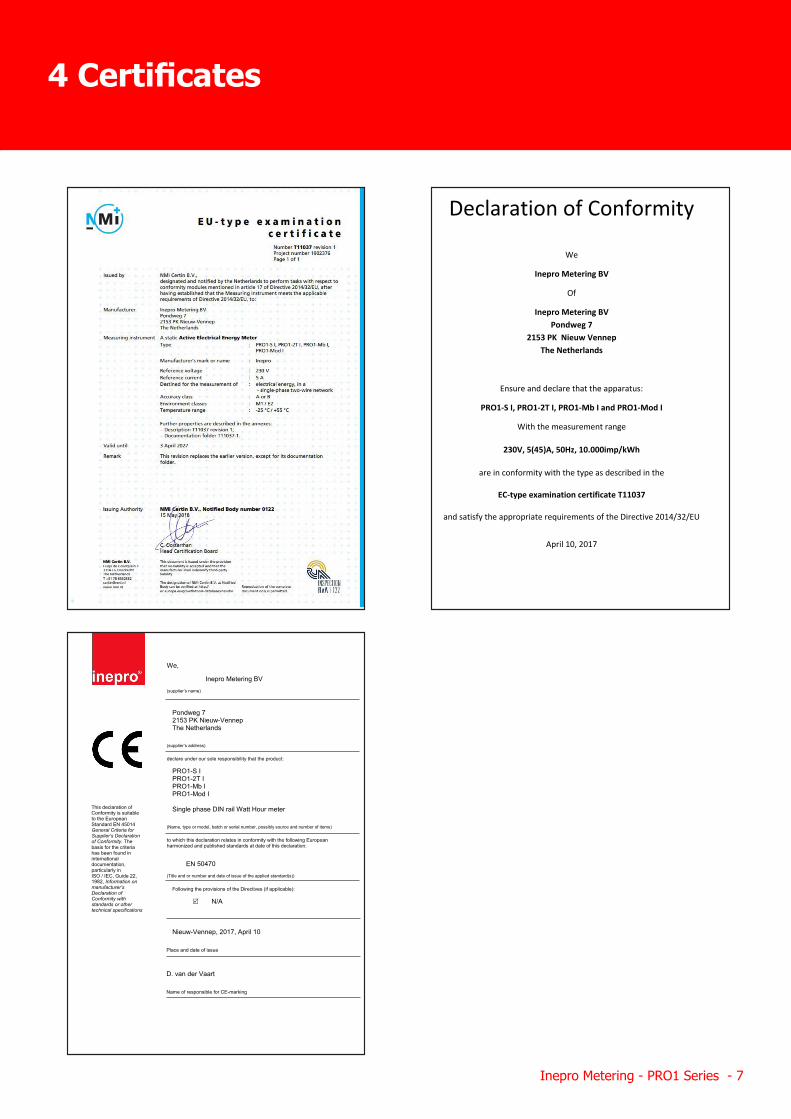
4 Certificates
We, Inepro Metering BV (supplier’s name)
Pondweg 7 2153 PK Nieuw-Vennep The Netherlands
(supplier’s address) declare under our sole responsibility that the product:
PRO1-S I PRO1-2T I PRO1-Mb I PRO1-Mod I
Single phase DIN rail Watt Hour meter
(Name, type or model, batch or serial number, possibly source and number of items) to which this declaration relates in conformity with the following European harmonized and published standards at date of this declaration:
EN 50470 (Title and or number and date of issue of the applied standard(s))
Following the provisions of the Directives (if applicable):
N/A
Nieuw-Vennep, 2017, April 10
Place and date of issue
D. van der Vaart Name of responsible for CE-marking
This declaration of Conformity is suitable to the European Standard EN 45014 General Criteria for Supplier’s Declaration of Conformity. The basis for the criteria has been found in international documentation, particularly in ISO / IEC, Guide 22, 1982, Information on manufacturer’s Declaration of Conformity with standards or other technical specifications
Declaration of Conformity
We
Inepro Metering BV
Of
Inepro Metering BV Pondweg 7
2153 PK Nieuw Vennep The Netherlands
Ensure and declare that the apparatus:
PRO1-S I, PRO1-2T I, PRO1-Mb I and PRO1-Mod I
With the measurement range
230V, 5(45)A, 50Hz, 10.000imp/kWh
are in conformity with the type as described in the
EC-type examination certificate T11037
and satisfy the appropriate requirements of the Directive 2014/32/EU
April 10, 2017
Daan van der Vaart
8 - Inepro Metering - PRO1 Series
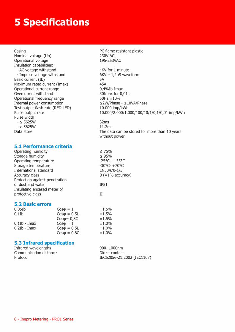
Casing PC flame resistant plasticNominal voltage (Un) 230V ACOperational voltage 195-253VACInsulation capabilities: - AC voltage withstand 4KV for 1 minute - Impulse voltage withstand 6KV – 1,2μS waveformBasic current (Ib) 5AMaximum rated current (Imax) 45AOperational current range 0,4%Ib-ImaxOvercurrent withstand 30Imax for 0,01sOperational frequency range 50Hz ±10%Internal power consumption ≤2W/Phase - ≤10VA/PhaseTest output flash rate (RED LED) 10.000 imp/kWhPulse output rate 10.000/2.000/1.000/100/10/1/0,1/0,01 imp/kWhPulse width - ≤ 5625W 32ms - > 5625W 11.2msData store The data can be stored for more than 10 years without power
5.1 Performance criteriaOperating humidity ≤ 75%Storage humidity ≤ 95%Operating temperature -25°C - +55°CStorage temperature -30°C- +70°CInternational standard EN50470-1/3Accuracy class B (=1% accuracy)Protection against penetrationof dust and water IP51Insulating encased meter ofprotective class II
5.2 Basic errors0,05Ib Cosφ = 1 ±1,5%0,1Ib Cosφ = 0,5L ±1,5% Cosφ= 0,8C ±1,5%0,1Ib - Imax Cosφ = 1 ±1,0%0,2Ib - Imax Cosφ = 0,5L ±1,0% Cosφ = 0,8C ±1,0%
5.3 Infrared specificationInfrared wavelengths 900- 1000nmCommunication distance Direct contactProtocol IEC62056-21:2002 (IEC1107)
5 Specifications
Inepro Metering - PRO1 Series - 9
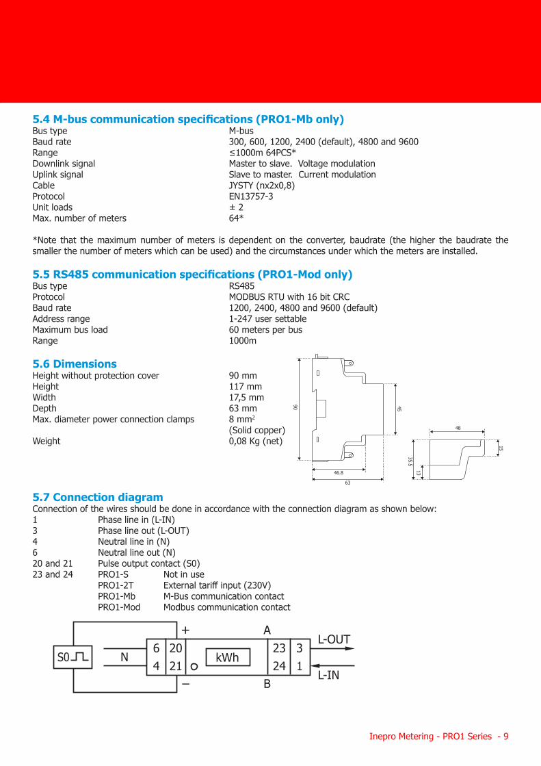
5.4 M-bus communication specifications (PRO1-Mb only)Bus type M-busBaud rate 300, 600, 1200, 2400 (default), 4800 and 9600Range ≤1000m 64PCS*Downlink signal Master to slave. Voltage modulationUplink signal Slave to master. Current modulationCable JYSTY (nx2x0,8)Protocol EN13757-3Unit loads ± 2 Max. number of meters 64*
*Note that the maximum number of meters is dependent on the converter, baudrate (the higher the baudrate the smaller the number of meters which can be used) and the circumstances under which the meters are installed.
5.5 RS485 communication specifications (PRO1-Mod only)Bus type RS485Protocol MODBUS RTU with 16 bit CRCBaud rate 1200, 2400, 4800 and 9600 (default)Address range 1-247 user settableMaximum bus load 60 meters per busRange 1000m
5.6 DimensionsHeight without protection cover 90 mmHeight 117 mmWidth 17,5 mmDepth 63 mmMax. diameter power connection clamps 8 mm2
(Solid copper)Weight 0,08 Kg (net)
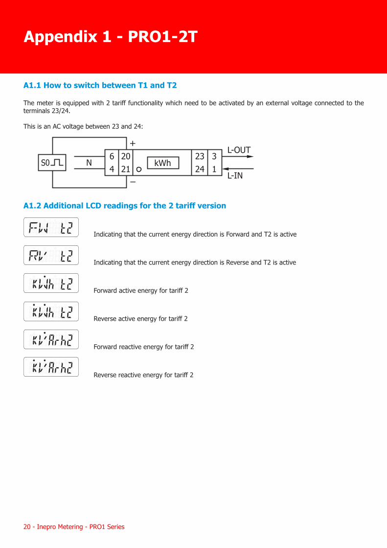
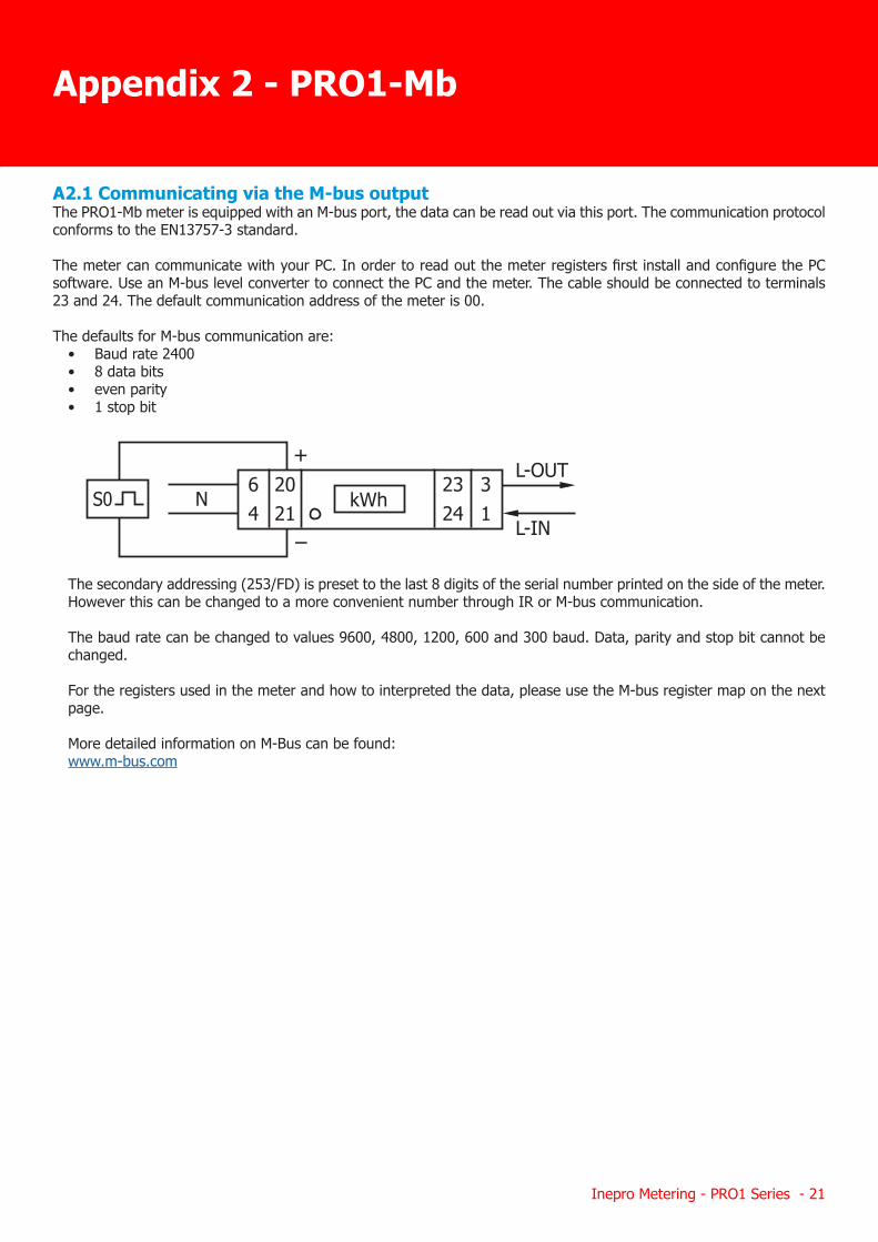
5.7 Connection diagramConnection of the wires should be done in accordance with the connection diagram as shown below:1 Phase line in (L-IN)3 Phase line out (L-OUT)4 Neutral line in (N)6 Neutral line out (N)20 and 21 Pulse output contact (S0)23 and 24 PRO1-S Not in use PRO1-2T External tariff input (230V) PRO1-Mb M-Bus communication contact PRO1-Mod Modbus communication contact
46.8
63
48
15
90 45
1335.5
+
64
2324
2021
A
B
31
L-IN
L-OUTNS0 kWh
10 - Inepro Metering - PRO1 Series
• The connecting wire, connecting the device to the outside circuit, should be sized in accordance with local regulations for the maximum amount of the current breaker or other overcurrent protection devices used in the circuit.
• An external switch or a circuit-breaker should be installed on the supply wires, which will be used to disconnect the meter and the device supplying energy. It is recommended that this switch or circuit-breaker is placed near the meter because that is more convenient for the operator. The switch or circuit-breaker should comply with the specifications of the building’s electrical design and all local regulations.
• An external fuse or thermal cut-off used as an overcurrent protection device for the meter must be installed on the supply side wires. It’s recommended that this protection device is also placed near the meter for the convenience of the operator. The overcurrent protection device should comply with the specifications of the building’s electrical design and all local regulations.
• This meter can be installed indoor, or outdoor enclosed in a meter box which is sufficiently protected, in accordance with local codes and regulations.
• To prevent tampering, an enclosure with a lock or a similar device can be used.• The meter has to be installed against a fire resistant wall.• The meter has to be installed in a well-ventilated and dry place.• The meter has to be installed in a protective box if the meter is exposed to dust or other contaminants.• The meter can be installed and used after being tested and can be sealed afterwards.• The device can be installed on a 35mm DIN rail.• The meter should be installed on a location where the meter can be read easily.• In case the meter is installed in an area with frequent surges for example due to thunderstorms, welding
machines, inverters etc., the meter is required to be protected with a Surge Protection Device.• The device should be sealed immediately after installing it in order to prevent tampering.
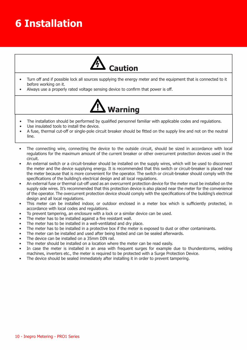
6 Installation
Caution• Turn off and if possible lock all sources supplying the energy meter and the equipment that is connected to it
before working on it.• Always use a properly rated voltage sensing device to confirm that power is off.
Warning• The installation should be performed by qualified personnel familiar with applicable codes and regulations.• Use insulated tools to install the device.• A fuse, thermal cut-off or single-pole circuit breaker should be fitted on the supply line and not on the neutral
line.
Inepro Metering - PRO1 Series - 11
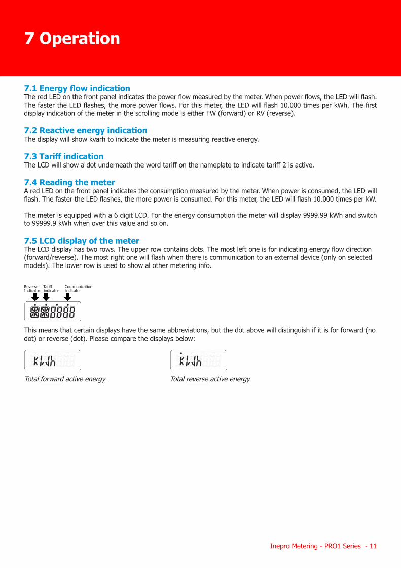
7.1 Energy flow indicationThe red LED on the front panel indicates the power flow measured by the meter. When power flows, the LED will flash. The faster the LED flashes, the more power flows. For this meter, the LED will flash 10.000 times per kWh. The first display indication of the meter in the scrolling mode is either FW (forward) or RV (reverse).
7.2 Reactive energy indicationThe display will show kvarh to indicate the meter is measuring reactive energy.
7.3 Tariff indicationThe LCD will show a dot underneath the word tariff on the nameplate to indicate tariff 2 is active.
7.4 Reading the meterA red LED on the front panel indicates the consumption measured by the meter. When power is consumed, the LED will flash. The faster the LED flashes, the more power is consumed. For this meter, the LED will flash 10.000 times per kW.
The meter is equipped with a 6 digit LCD. For the energy consumption the meter will display 9999.99 kWh and switch to 99999.9 kWh when over this value and so on.
7.5 LCD display of the meterThe LCD display has two rows. The upper row contains dots. The most left one is for indicating energy flow direction (forward/reverse). The most right one will flash when there is communication to an external device (only on selected models). The lower row is used to show al other metering info. Reverse Tariff Communication Indicator indicator indicator
This means that certain displays have the same abbreviations, but the dot above will distinguish if it is for forward (no dot) or reverse (dot). Please compare the displays below:
Total forward active energy Total reverse active energy
7 Operation
12 - Inepro Metering - PRO1 Series
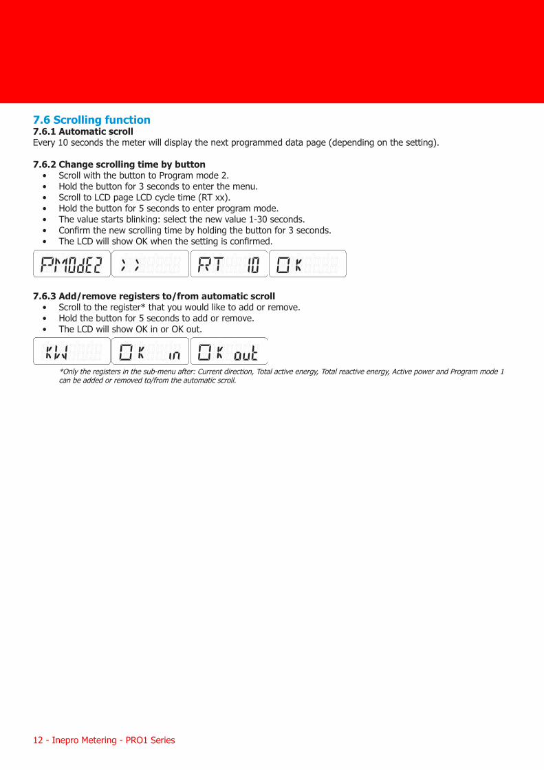
7.6 Scrolling function7.6.1 Automatic scrollEvery 10 seconds the meter will display the next programmed data page (depending on the setting).
7.6.2 Change scrolling time by button• Scroll with the button to Program mode 2.• Hold the button for 3 seconds to enter the menu.• Scroll to LCD page LCD cycle time (RT xx).• Hold the button for 5 seconds to enter program mode.• The value starts blinking: select the new value 1-30 seconds.• Confirm the new scrolling time by holding the button for 3 seconds.• The LCD will show OK when the setting is confirmed.
7.6.3 Add/remove registers to/from automatic scroll• Scroll to the register* that you would like to add or remove.• Hold the button for 5 seconds to add or remove.• The LCD will show OK in or OK out.
*Only the registers in the sub-menu after: Current direction, Total active energy, Total reactive energy, Active power and Program mode 1 can be added or removed to/from the automatic scroll.
Inepro Metering - PRO1 Series - 13
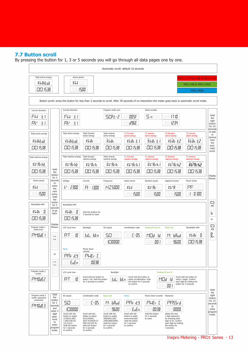
7.7 Button scrollBy pressing the button for 1, 3 or 5 seconds you will go through all data pages one by one.
Automatic scroll: default 10 seconds
Button scroll: press the button for less than 3 seconds to scroll. After 30 seconds of no interaction the meter goes back to automatic scroll mode.
PRO1-2T, PRO1-MB & PRO1-MOD
PRO1-MB & PRO1-MOD
PRO1-MOD
Current direction Current direction Program verify sum Serial number
Total active energy Total forward active energy
Total reverse active energy
T1 forward active energy
T1 reverse active energy
T2 forward active energy
T2 reverse active energy
Total reactive energy Total forward reactive energy
Total reverse reactive energy
T1 forward reactive energy
T1 reverse reactive energy
T2 forward reactive energy
T2 reverse reactive energy
Voltage Current Frequency Active power Reactive power Apparent power Power factor
Total active energy
Total reactive energy
Active power
Resettable kWhResettable kWh
Program mode 1 (read only)
LCD cycle time Backlight S0 output Combination code Modbus/M-bus ID Baud rate Resettable kWh
Parity Power down counter
LCD cycle time Backlight Modbus/M-bus ID
S0 output Combination code Baud rate Parity Power down counter Password
Program mode 2 (write)
Program mode 3(write: password
protected)
Hold the
button for 3
seconds to
enter the next
menu. Hold the
button for 3
seconds to go back.
Display Shows:
or
Hold the right
button for ≥5
seconds to add
or remove from the
auto- matic scroll.
Display Shows:
or
Hold the right
button for ≥5
seconds to
enter program mode.
Hold the
button for 3
seconds and
enter 4 digit pass- word
to enter
program mode.
Hold the buttons for 5 seconds to reset.
Scroll with the button to select 1-30. Hold the button for 3 seconds to confirm.
Scroll with the button to select on/off/button. Hold the button for 3 seconds to confirm.
Scroll with the button to select 3 digits. Confirm each digit by holding the button for 3 seconds.
Scroll with the button to select 10.000/2.000/ 1.000/100/10/ 1/0,1/0,01. Hold the button for 3 seconds to confirm.
Scroll with the button to select 01(F)/04(R)/ 05(F+R)/06(R-F)/ 09(F-R)/10(F-R). Hold the button for 3 seconds to confirm.
Scroll with the button to select 300/600/1200/ 2400/4800/9600. Hold the button for 3 seconds to confirm.
Scroll with the button to select even/none/odd. Hold the button for 3 seconds to confirm.
Hold the button for 3 seconds to reset.
Select the new 4 digit password by choosing each digit (0-9). Confirm each digit by holding the button for 3 seconds.
Total active energy Active power
14 - Inepro Metering - PRO1 Series
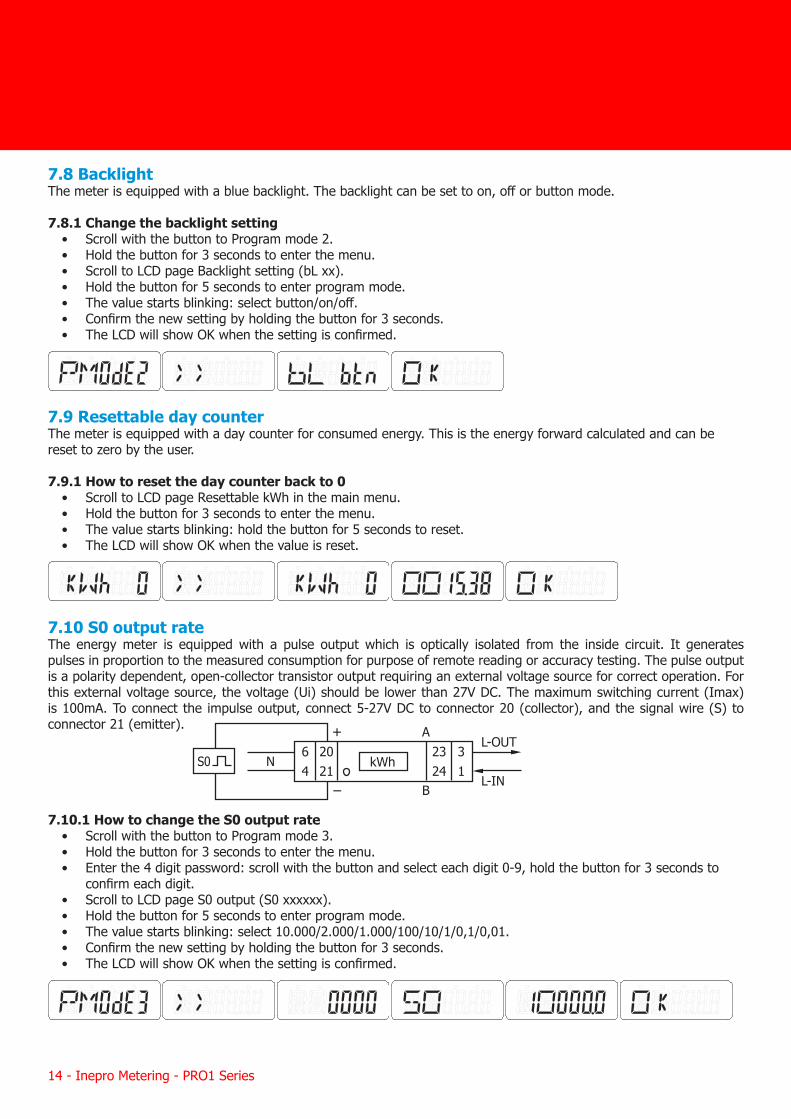
7.8 BacklightThe meter is equipped with a blue backlight. The backlight can be set to on, off or button mode.
7.8.1 Change the backlight setting• Scroll with the button to Program mode 2.• Hold the button for 3 seconds to enter the menu.• Scroll to LCD page Backlight setting (bL xx).• Hold the button for 5 seconds to enter program mode.• The value starts blinking: select button/on/off.• Confirm the new setting by holding the button for 3 seconds.• The LCD will show OK when the setting is confirmed.
7.9 Resettable day counterThe meter is equipped with a day counter for consumed energy. This is the energy forward calculated and can be reset to zero by the user.
7.9.1 How to reset the day counter back to 0• Scroll to LCD page Resettable kWh in the main menu.• Hold the button for 3 seconds to enter the menu.• The value starts blinking: hold the button for 5 seconds to reset.• The LCD will show OK when the value is reset.
7.10 S0 output rateThe energy meter is equipped with a pulse output which is optically isolated from the inside circuit. It generates pulses in proportion to the measured consumption for purpose of remote reading or accuracy testing. The pulse output is a polarity dependent, open-collector transistor output requiring an external voltage source for correct operation. For this external voltage source, the voltage (Ui) should be lower than 27V DC. The maximum switching current (Imax) is 100mA. To connect the impulse output, connect 5-27V DC to connector 20 (collector), and the signal wire (S) to connector 21 (emitter).
7.10.1 How to change the S0 output rate• Scroll with the button to Program mode 3.• Hold the button for 3 seconds to enter the menu.• Enter the 4 digit password: scroll with the button and select each digit 0-9, hold the button for 3 seconds to
confirm each digit.• Scroll to LCD page S0 output (S0 xxxxxx).• Hold the button for 5 seconds to enter program mode.• The value starts blinking: select 10.000/2.000/1.000/100/10/1/0,1/0,01.• Confirm the new setting by holding the button for 3 seconds.• The LCD will show OK when the setting is confirmed.
+
64
2324
2021
A
B
31
L-IN
L-OUTNS0 kWh
Inepro Metering - PRO1 Series - 15
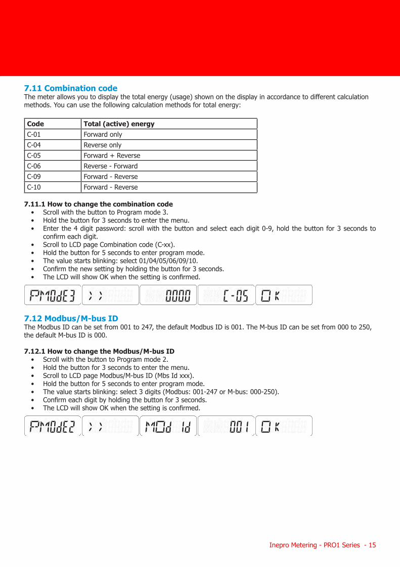
7.11 Combination codeThe meter allows you to display the total energy (usage) shown on the display in accordance to different calculation methods. You can use the following calculation methods for total energy:
Code Total (active) energyC-01 Forward onlyC-04 Reverse onlyC-05 Forward + ReverseC-06 Reverse - ForwardC-09 Forward - ReverseC-10 Forward - Reverse
7.11.1 How to change the combination code
• Scroll with the button to Program mode 3.• Hold the button for 3 seconds to enter the menu.• Enter the 4 digit password: scroll with the button and select each digit 0-9, hold the button for 3 seconds to
confirm each digit.• Scroll to LCD page Combination code (C-xx).• Hold the button for 5 seconds to enter program mode.• The value starts blinking: select 01/04/05/06/09/10.• Confirm the new setting by holding the button for 3 seconds.• The LCD will show OK when the setting is confirmed.
7.12 Modbus/M-bus IDThe Modbus ID can be set from 001 to 247, the default Modbus ID is 001. The M-bus ID can be set from 000 to 250, the default M-bus ID is 000.
7.12.1 How to change the Modbus/M-bus ID• Scroll with the button to Program mode 2.• Hold the button for 3 seconds to enter the menu.• Scroll to LCD page Modbus/M-bus ID (Mbs Id xxx).• Hold the button for 5 seconds to enter program mode.• The value starts blinking: select 3 digits (Modbus: 001-247 or M-bus: 000-250).• Confirm each digit by holding the button for 3 seconds.• The LCD will show OK when the setting is confirmed.
16 - Inepro Metering - PRO1 Series
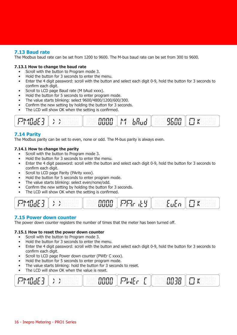
7.13 Baud rateThe Modbus baud rate can be set from 1200 to 9600. The M-bus baud rate can be set from 300 to 9600. 7.13.1 How to change the baud rate
• Scroll with the button to Program mode 3.• Hold the button for 3 seconds to enter the menu.• Enter the 4 digit password: scroll with the button and select each digit 0-9, hold the button for 3 seconds to
confirm each digit.• Scroll to LCD page Baud rate (M bAud xxxx).• Hold the button for 5 seconds to enter program mode.• The value starts blinking: select 9600/4800/1200/600/300.• Confirm the new setting by holding the button for 3 seconds.• The LCD will show OK when the setting is confirmed.
7.14 ParityThe Modbus parity can be set to even, none or odd. The M-bus parity is always even. 7.14.1 How to change the parity
• Scroll with the button to Program mode 3.• Hold the button for 3 seconds to enter the menu.• Enter the 4 digit password: scroll with the button and select each digit 0-9, hold the button for 3 seconds to
confirm each digit.• Scroll to LCD page Parity (PArity xxxx).• Hold the button for 5 seconds to enter program mode.• The value starts blinking: select even/none/odd.• Confirm the new setting by holding the button for 3 seconds.• The LCD will show OK when the setting is confirmed.
7.15 Power down counterThe power down counter registers the number of times that the meter has been turned off. 7.15.1 How to reset the power down counter
• Scroll with the button to Program mode 3.• Hold the button for 3 seconds to enter the menu.• Enter the 4 digit password: scroll with the button and select each digit 0-9, hold the button for 3 seconds to
confirm each digit.• Scroll to LCD page Power down counter (PWEr C xxxx).• Hold the button for 5 seconds to enter program mode.• The value starts blinking: hold the button for 3 seconds to reset.• The LCD will show OK when the value is reset.
Inepro Metering - PRO1 Series - 17
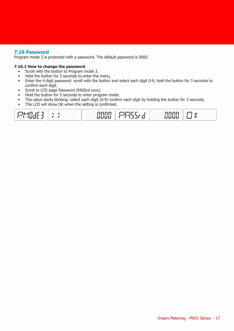
7.16 PasswordProgram mode 3 is protected with a password. The default password is 0000. 7.16.1 How to change the password
• Scroll with the button to Program mode 3.• Hold the button for 3 seconds to enter the menu.• Enter the 4 digit password: scroll with the button and select each digit 0-9, hold the button for 3 seconds to
confirm each digit.• Scroll to LCD page Password (PASSrd xxxx).• Hold the button for 5 seconds to enter program mode.• The value starts blinking: select each digit (0-9) confirm each digit by holding the button for 3 seconds.• The LCD will show OK when the setting is confirmed.
18 - Inepro Metering - PRO1 Series
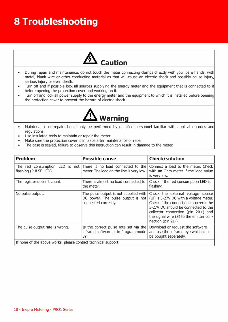
8 Troubleshooting
Caution• During repair and maintenance, do not touch the meter connecting clamps directly with your bare hands, with
metal, blank wire or other conducting material as that will cause an electric shock and possibly cause injury, serious injury or even death.
• Turn off and if possible lock all sources supplying the energy meter and the equipment that is connected to it before opening the protection cover and working on it.
• Turn off and lock all power supply to the energy meter and the equipment to which it is installed before opening the protection cover to prevent the hazard of electric shock.
Warning• Maintenance or repair should only be performed by qualified personnel familiar with applicable codes and
regulations.• Use insulated tools to maintain or repair the meter.• Make sure the protection cover is in place after maintenance or repair.• The case is sealed, failure to observe this instruction can result in damage to the meter.
Problem Possible cause Check/solutionThe red consumption LED is not flashing (PULSE LED).
There is no load connected to the meter. The load on the line is very low.
Connect a load to the meter. Check with an Ohm-meter if the load value is very low.
The register doesn’t count. There is almost no load connected to the meter.
Check if the red consumption LED is flashing.
No pulse output. The pulse output is not supplied with DC power. The pulse output is not connected correctly.
Check the external voltage source (Ui) is 5-27V DC with a voltage meter. Check if the connection is correct: the 5-27V DC should be connected to the collector connection (pin 20+) and the signal wire (S) to the emitter con-nection (pin 21-).
The pulse output rate is wrong. Is the correct pulse rate set via the infrared software or in Program mode 3?
Download or request the software and use the infrared eye which can be bought seperately.
If none of the above works, please contact technical support

Inepro Metering - PRO1 Series - 19
8.1 List of errors in displayIt could be that one of the following errors is displayed on the meter:
8.2 Technical supportFor questions about one of our products please contact:
• Your local Inepro Metering distributor• Email: [email protected]• Website: www.ineprometering.com
Display shows Kind of errors MeasuresErr 01 EEPROM error Please contact technical support for a
meter replacement.Err 02 Program code checksum error Please contact technical support for a
meter replacement.
20 - Inepro Metering - PRO1 Series
A1.1 How to switch between T1 and T2
The meter is equipped with 2 tariff functionality which need to be activated by an external voltage connected to the terminals 23/24.
This is an AC voltage between 23 and 24:
A1.2 Additional LCD readings for the 2 tariff version
Indicating that the current energy direction is Forward and T2 is active
Indicating that the current energy direction is Reverse and T2 is active
Forward active energy for tariff 2
Reverse active energy for tariff 2
Forward reactive energy for tariff 2
Reverse reactive energy for tariff 2
Appendix 1 - PRO1-2T
+
64
2324
2021
31
L-IN
L-OUTNS0 kWh
Inepro Metering - PRO1 Series - 21
A2.1 Communicating via the M-bus outputThe PRO1-Mb meter is equipped with an M-bus port, the data can be read out via this port. The communication protocol conforms to the EN13757-3 standard.
The meter can communicate with your PC. In order to read out the meter registers first install and configure the PC software. Use an M-bus level converter to connect the PC and the meter. The cable should be connected to terminals 23 and 24. The default communication address of the meter is 00.
The defaults for M-bus communication are:• Baud rate 2400 • 8 data bits• even parity• 1 stop bit
The secondary addressing (253/FD) is preset to the last 8 digits of the serial number printed on the side of the meter. However this can be changed to a more convenient number through IR or M-bus communication.
The baud rate can be changed to values 9600, 4800, 1200, 600 and 300 baud. Data, parity and stop bit cannot be changed.
For the registers used in the meter and how to interpreted the data, please use the M-bus register map on the next page.
More detailed information on M-Bus can be found:www.m-bus.com
Appendix 2 - PRO1-Mb
+
64
2324
2021
31
L-IN
L-OUTNS0 kWh
22 - Inepro Metering - PRO1 Series
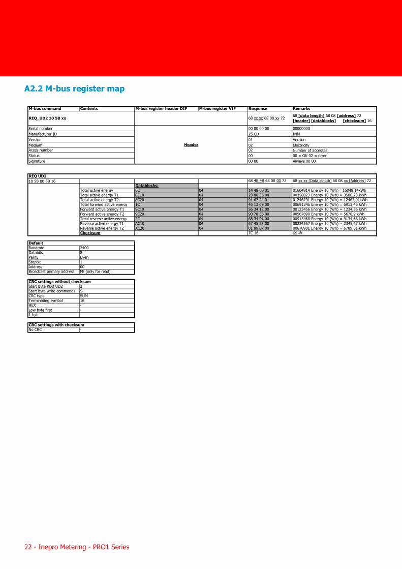
A2.2 M-bus register map
M-bus command Contents M-bus register header DIF M-bus register VIF Response Remarks
00 00 00 00 0000000025 CD INM01 Version02 Electricity02 Number of accesses00 00 = OK 02 = error00 00 Always 00 00
10 5B 00 5B 16 68 4B 4B 68 08 00 72 68 xx xx [Data length] 68 08 xx [Address] 72Datablocks:
Total active energy 0C 04 14 48 60 01 01604814 Energy 10 (Wh) =16048,14kWhTotal active energy T1 8C10 04 23 80 35 00 00358023 Energy 10 (Wh) = 3580,23 kWhTotal active energy T2 8C20 04 91 67 24 01 01246791 Energy 10 (Wh) = 12467,91kWhTotal forward active energy 1C 04 46 13 69 00 00691346 Energy 10 (Wh) = 6913,46 kWhForward active energy T1 9C10 04 56 34 12 00 00123456 Energy 10 (Wh) = 1234,56 kWhForward active energy T2 9C20 04 90 78 56 00 00567890 Energy 10 (Wh) = 5678,9 kWhTotal reverse active energy 2C 04 68 34 91 00 00913468 Energy 10 (Wh) = 9134,68 kWhReverse active energy T1 AC10 04 67 45 23 00 00234567 Energy 10 (Wh) = 2345,67 kWhReverse active energy T2 AC20 04 01 89 67 00 00678901 Energy 10 (Wh) = 6789,01 kWhChecksum 7C 16 xx 16
Baudrate 2400Databits 8Parity EvenStopbit 1Address 00Broadcast primary address FE (only for read)
Start byte REQ UD2 2Start byte write commands 5CRC type SUMTerminating symbol 16HEX -Low byte first -1 byte -
CRC settings with checksumNo CRC -
Default
CRC settings without checksum
REQ UD2
68 xx xx 68 08 xx 72 68 [data length] 68 08 [address] 72 [header] [datablocks] [checksum] 16
Header
Serial numberManufacturer IDVersionMedium Acces numberStatusSignature
REQ_UD2 10 5B xx
Inepro Metering - PRO1 Series - 23
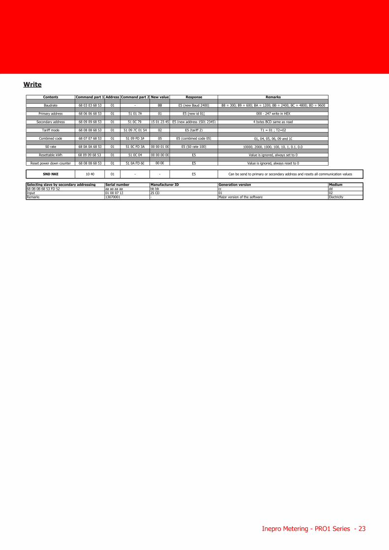
WriteContents Command part 1 Address Command part 2 New value Response Remarks
Baudrate 68 03 03 68 53 01 - BB E5 (new Baud 2400) B8 = 300; B9 = 600; BA = 1200; BB = 2400; BC = 4800; BD = 9600
Primary address 68 06 06 68 53 01 51 01 7A 01 E5 (new id 01) 000 - 247 write in HEX
Secondary address 68 09 09 68 53 01 51 0C 79 15 01 23 45 E5 (new address 1501 2345) 4 bytes BCD same as read
Tariff mode 68 08 08 68 53 01 51 09 7C 01 54 02 E5 (tariff 2) T1 = 01 ; T2=02
Combined code 68 07 07 68 53 01 51 09 FD 3A 05 E5 (combined code 05) 01, 04, 05, 06, 09 and 10
S0 rate 68 0A 0A 68 53 01 51 0C FD 3A 00 00 01 00 E5 (S0 rate 100) 10000, 2000, 1000, 100, 10, 1, 0.1, 0.01
Resettable kWh 68 09 09 68 53 01 51 0C 04 00 00 00 00 E5 Value is ignored, always set to 0
Reset power down counter 68 08 08 68 53 01 51 0A FD 60 00 00 E5 Value is ignored, always reset to 0
Generation versioncc01Major version of the software
Input 01 00 07 13 25 CD 02Remarks 13070001 - Electricity
68 0B 0B 68 53 FD 52 aa aa aa aa bb bb dd
SND NKE 10 40 01 - - E5 Can be send to primary or secondary address and resets all communication values
Selecting slave by secondary addressing Serial number Manufacturer ID Medium

24 - Inepro Metering - PRO1 Series
A3.1 Communicating via the Modbus outputThe meter can communicate with your PC. In order to read out the meter registers first install and configure the PC software. Use an RS485 level converter to connect the PC and the meter. The cable should be connected to terminals 23 and 24. The default communication address of the meter is 01.
The PRO1-Mod can be connected for Modbus communication. The Modbus implementation used is Modbus basic (standard). This means the following:
• Baud rate 9600 • 8 data bits• even parity• 1 stop bit
The baud rate can be lowered to values 4800, 2400, 1200. The parity can be set to none or odd. Data and stopbit cannot be changed.
When connecting the meter through a serial converter (RS485) for testing, please be aware that because of not implementing the complete Modbus infrastructure, there will be a need to put an additional resistor (120 ohms/ 0.25 watts) across the terminals (23 & 24) on the meter side.
For the registers used in the meter and how to interpreted the data, please use the Modbus register map on the next pages.
More info on Modbus can be found:Physical: http://www.modbus.org/docs/Modbus_over_serial_line_V1_02.pdfProtocol: http://www.modbus.org/docs/Modbus_Application_Protocol_V1_1b3.pdf
Appendix 3 - PRO1-Mod
+
64
2324
2021
31
L-IN
L-OUTNS0 kWh
Inepro Metering - PRO1 Series - 25
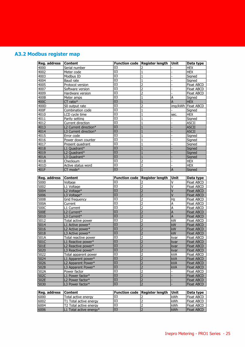
A3.2 Modbus register mapReg. address Content Function code Register length Unit Data type4000 Serial number 03 2 - HEX4002 Meter code 03 1 - HEX4003 Modbus ID 03 1 - Signed4004 Baud rate 03 1 - Signed4005 Protocol version 03 2 - Float ABCD4007 Software version 03 2 - Float ABCD4009 Hardware version 03 2 - Float ABCD400B Meter amps 03 1 A Signed400C CT ratio* 03 1 A HEX400D S0 output rate 03 2 imp/kWh Float ABCD400F Combination code 03 1 - Signed4010 LCD cycle time 03 1 sec. HEX4011 Parity setting 03 1 - Signed4012 Current direction 03 1 - ASCII4013 L2 Current direction* 03 1 - ASCII4014 L3 Current direction* 03 1 - ASCII4015 Error code 03 1 - Signed4016 Power down counter 03 1 - Signed4017 Present quadrant 03 1 - Signed4018 L1 Quadrant* 03 1 - Signed4019 L2 Quadrant* 03 1 - Signed401A L3 Quadrant* 03 1 - Signed401B Checksum 03 2 - HEX401D Active status word 03 2 - HEX401F CT mode* 03 1 A Signed
Reg. address Content Function code Register length Unit Data type5000 Voltage 03 2 V Float ABCD5002 L1 Voltage 03 2 V Float ABCD5004 L2 Voltage* 03 2 V Float ABCD5006 L3 Voltage* 03 2 V Float ABCD5008 Grid frequency 03 2 Hz Float ABCD500A Current 03 2 A Float ABCD500C L1 Current 03 2 A Float ABCD500E L2 Current* 03 2 A Float ABCD5010 L3 Current* 03 2 A Float ABCD5012 Total active power 03 2 kW Float ABCD5014 L1 Active power* 03 2 kW Float ABCD5016 L2 Active power* 03 2 kW Float ABCD5018 L3 Active power* 03 2 kW Float ABCD501A Total reactive power 03 2 kvar Float ABCD501C L1 Reactive power* 03 2 kvar Float ABCD501E L2 Reactive power* 03 2 kvar Float ABCD5020 L3 Reactive power* 03 2 kvar Float ABCD5022 Total apparent power 03 2 kVA Float ABCD5024 L1 Apparent power* 03 2 kVA Float ABCD5026 L2 Apparent Power* 03 2 kVA Float ABCD5028 L3 Apparent Power* 03 2 kVA Float ABCD502A Power factor 03 2 - Float ABCD502C L1 Power factor* 03 2 - Float ABCD502E L2 Power factor* 03 2 - Float ABCD5030 L3 Power factor* 03 2 - Float ABCD
Reg. address Content Function code Register length Unit Data type6000 Total active energy 03 2 kWh Float ABCD6002 T1 Total active energy 03 2 kWh Float ABCD6004 T2 Total active energy 03 2 kWh Float ABCD6006 L1 Total active energy* 03 2 kWh Float ABCD
26 - Inepro Metering - PRO1 Series
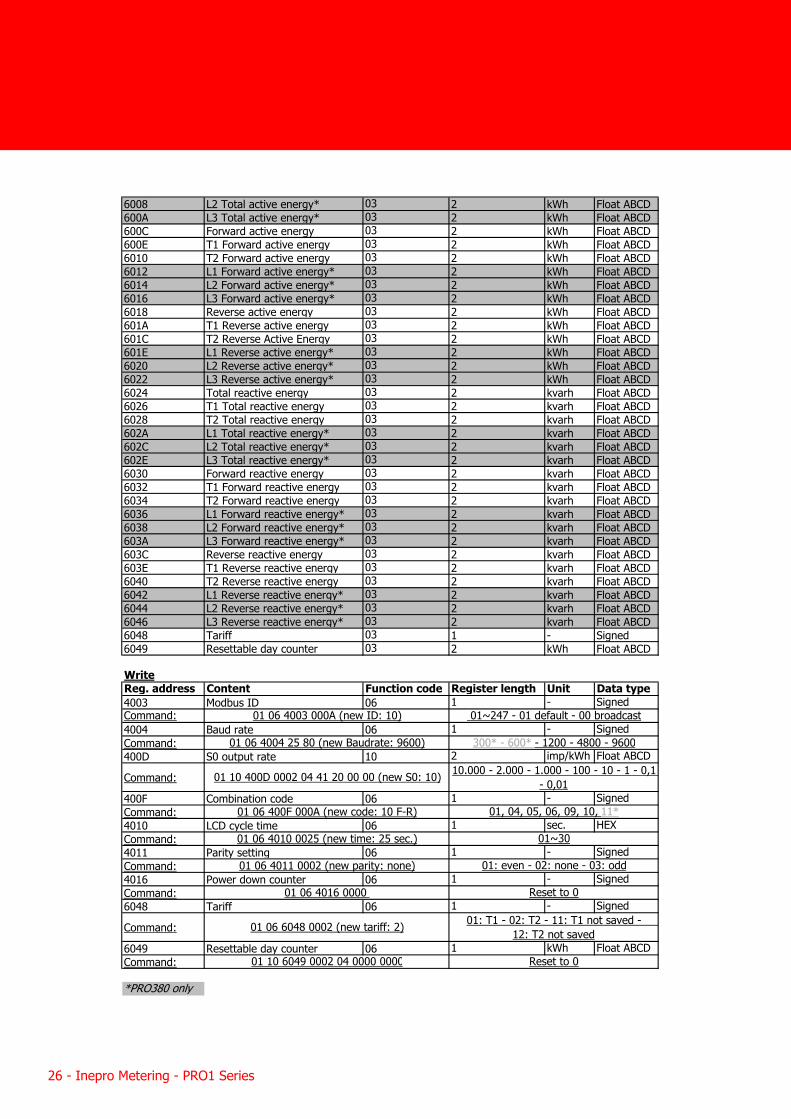
6008 L2 Total active energy* 03 2 kWh Float ABCD600A L3 Total active energy* 03 2 kWh Float ABCD600C Forward active energy 03 2 kWh Float ABCD600E T1 Forward active energy 03 2 kWh Float ABCD6010 T2 Forward active energy 03 2 kWh Float ABCD6012 L1 Forward active energy* 03 2 kWh Float ABCD6014 L2 Forward active energy* 03 2 kWh Float ABCD6016 L3 Forward active energy* 03 2 kWh Float ABCD6018 Reverse active energy 03 2 kWh Float ABCD601A T1 Reverse active energy 03 2 kWh Float ABCD601C T2 Reverse Active Energy 03 2 kWh Float ABCD601E L1 Reverse active energy* 03 2 kWh Float ABCD6020 L2 Reverse active energy* 03 2 kWh Float ABCD6022 L3 Reverse active energy* 03 2 kWh Float ABCD6024 Total reactive energy 03 2 kvarh Float ABCD6026 T1 Total reactive energy 03 2 kvarh Float ABCD6028 T2 Total reactive energy 03 2 kvarh Float ABCD602A L1 Total reactive energy* 03 2 kvarh Float ABCD602C L2 Total reactive energy* 03 2 kvarh Float ABCD602E L3 Total reactive energy* 03 2 kvarh Float ABCD6030 Forward reactive energy 03 2 kvarh Float ABCD6032 T1 Forward reactive energy 03 2 kvarh Float ABCD6034 T2 Forward reactive energy 03 2 kvarh Float ABCD6036 L1 Forward reactive energy* 03 2 kvarh Float ABCD6038 L2 Forward reactive energy* 03 2 kvarh Float ABCD603A L3 Forward reactive energy* 03 2 kvarh Float ABCD603C Reverse reactive energy 03 2 kvarh Float ABCD603E T1 Reverse reactive energy 03 2 kvarh Float ABCD6040 T2 Reverse reactive energy 03 2 kvarh Float ABCD6042 L1 Reverse reactive energy* 03 2 kvarh Float ABCD6044 L2 Reverse reactive energy* 03 2 kvarh Float ABCD6046 L3 Reverse reactive energy* 03 2 kvarh Float ABCD6048 Tariff 03 1 - Signed6049 Resettable day counter 03 2 kWh Float ABCD
WriteReg. address Content Function code Register length Unit Data type4003 Modbus ID 06 1 - SignedCommand:4004 Baud rate 06 1 - SignedCommand:400D S0 output rate 10 2 imp/kWh Float ABCD
Command:
400F Combination code 06 1 - SignedCommand:4010 LCD cycle time 06 1 sec. HEXCommand:4011 Parity setting 06 1 - SignedCommand:4016 Power down counter 06 1 - SignedCommand:6048 Tariff 06 1 - Signed
Command:
6049 Resettable day counter 06 1 kWh Float ABCDCommand:
*PRO380 only
01 10 6049 0002 04 0000 0000 Reset to 0
01 06 4010 0025 (new time: 25 sec.) 01~30
01: even - 02: none - 03: odd
01 06 4016 0000 Reset to 0
01 06 6048 0002 (new tariff: 2) 01: T1 - 02: T2 - 11: T1 not saved - 12: T2 not saved
01 06 4011 0002 (new parity: none)
01 06 400F 000A (new code: 10 F-R) 01, 04, 05, 06, 09, 10, 11*
01 10 400D 0002 04 41 20 00 00 (new S0: 10)
01 06 4003 000A (new ID: 10) 01~247 - 01 default - 00 broadcast
01 06 4004 25 80 (new Baudrate: 9600)
10.000 - 2.000 - 1.000 - 100 - 10 - 1 - 0,1 - 0,01
300* - 600* - 1200 - 4800 - 9600
Inepro Metering - PRO1 Series - 27
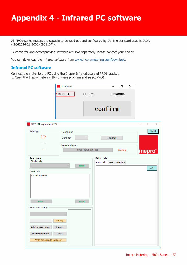
All PRO1-series meters are capable to be read out and configured by IR. The standard used is IRDA (IEC62056-21:2002 (IEC1107)).
IR converter and accompanying software are sold separately. Please contact your dealer.
You can download the infrared software from www.ineprometering.com/download.
Infrared PC softwareConnect the meter to the PC using the Inepro Infrared eye and PRO1 bracket. 1. Open the Inepro metering IR software program and select PRO1.
Appendix 4 - Infrared PC software
1
28 - Inepro Metering - PRO1 Series
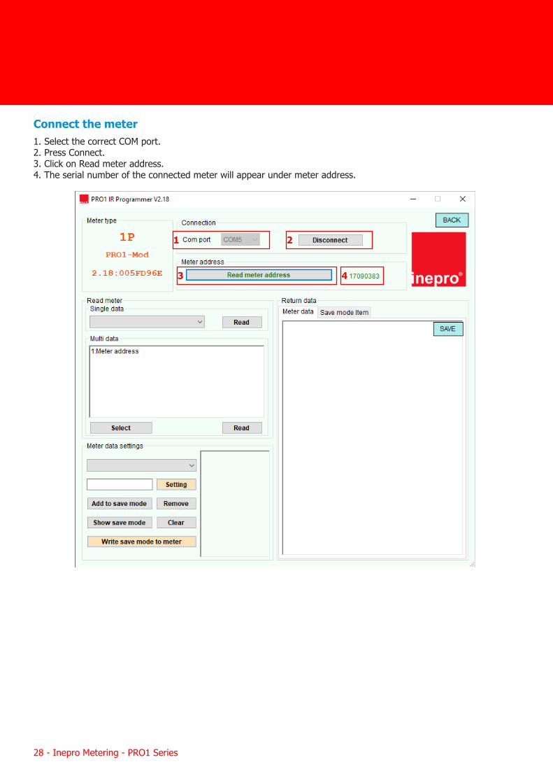
Connect the meter 1. Select the correct COM port.2. Press Connect. 3. Click on Read meter address. 4. The serial number of the connected meter will appear under meter address.
1 2
3 4
Inepro Metering - PRO1 Series - 29
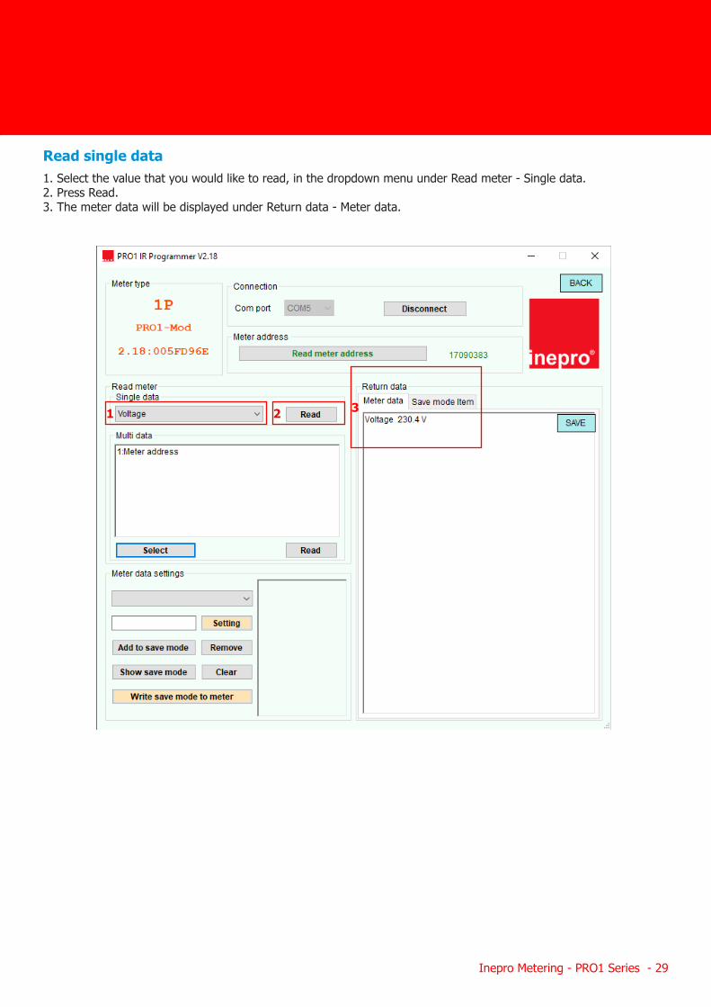
Read single data1. Select the value that you would like to read, in the dropdown menu under Read meter - Single data. 2. Press Read. 3. The meter data will be displayed under Return data - Meter data.
1 2 3
30 - Inepro Metering - PRO1 Series
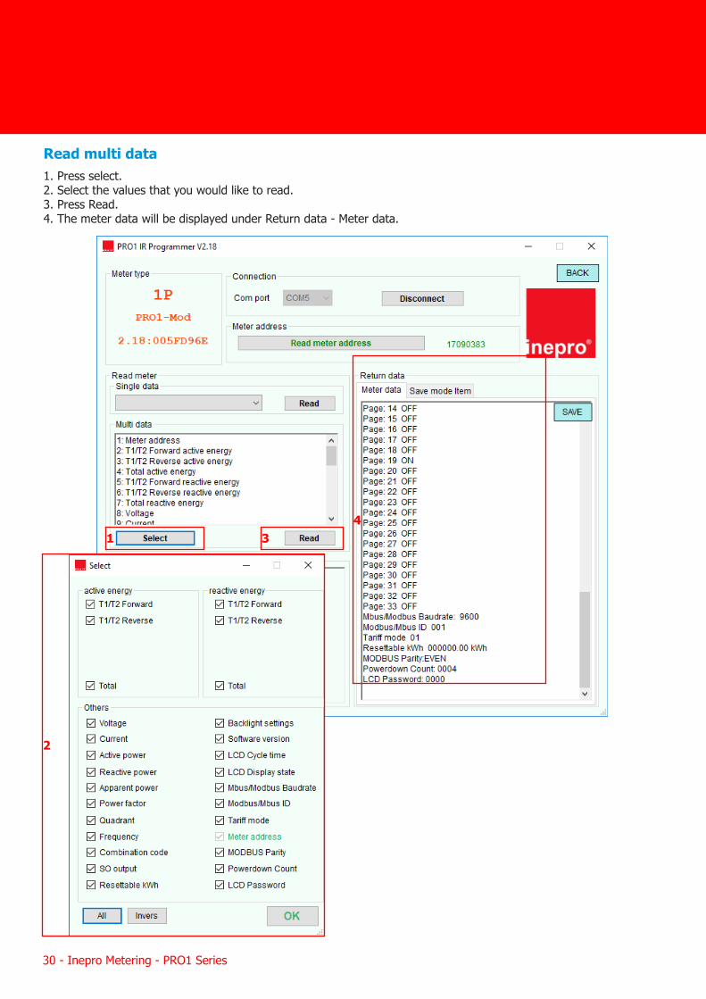
Read multi data 1. Press select. 2. Select the values that you would like to read.3. Press Read. 4. The meter data will be displayed under Return data - Meter data.
4
2
1 3
Inepro Metering - PRO1 Series - 31
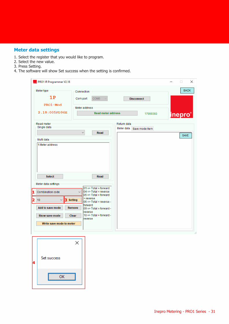
Meter data settings1. Select the register that you would like to program. 2. Select the new value. 3. Press Setting.4. The software will show Set success when the setting is confirmed.
1
2 3
4
32 - Inepro Metering - PRO1 Series
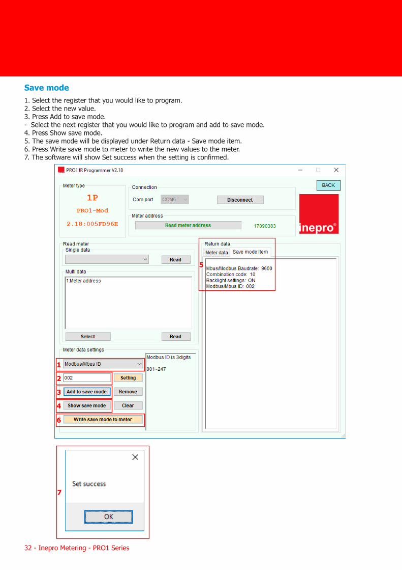
Save mode 1. Select the register that you would like to program. 2. Select the new value. 3. Press Add to save mode. - Select the next register that you would like to program and add to save mode.4. Press Show save mode.5. The save mode will be displayed under Return data - Save mode item.6. Press Write save mode to meter to write the new values to the meter.7. The software will show Set success when the setting is confirmed.
1
2
3
4
5
6
7