printing from undefined - ohio weather, home of n74gm · ensure injectors twist freely and are not...
TRANSCRIPT

1997-98 ENGINES
1.8L 4-Cylinder
ENGINE IDENTIFICATION
Engines can be identified by engine model and number. See ENGINE IDENTIFICATION CODE . On Miata, engine model and number are stamped on flange at upper right rear of cylinder block deck, as viewed from flywheel. On Protege, engine model and number are stamped on flange at upper left rear of cylinder block deck, as viewed from flywheel.
ENGINE IDENTIFICATION CODE
ADJUSTMENTS
VALVE CLEARANCE ADJUSTMENT
REMOVAL & INSTALLATION
FUEL PRESSURE RELEASE & PRIMING
Releasing Pressure (Miata)
Locate and remove fuel pump relay from under left side of dash, near steering column. Start engine and allow to stall. After engine stalls, attempt to restart engine to ensure no residual pressure exists. Turn ignition off and reinstall fuel pump relay. When disconnecting fuel hoses, cover connection with shop rag to catch fuel leakage. To avoid excessive cranking after servicing, prime fuel system before starting engine.
Releasing Pressure (Protege)
NOTE: For repair procedures not covered in this article, see ENGINE OVERHAUL PROCEDURES article in GENERAL INFORMATION.
Application CodeMiata & Protege (1.8L DOHC) BP
NOTE: Valve clearance is not adjustable. Some Hydraulic Lash Adjuster (HLA) noise may occur during engine start-up. Noise should disappear after engine reaches normal operating temperature. If noise persists and oil level is okay, change engine oil. If oil change does not reduce noise, check with manufacturer for modified HLA.
NOTE: For reassembly reference, label all electrical connectors, vacuum hoses and fuel lines before removal. Also place mating marks on engine hood and other major assemblies before removal.
1997 Mazda MX-5 Miata
1997-98 ENGINES 1.8L 4-Cylinder
1997 Mazda MX-5 Miata
1997-98 ENGINES 1.8L 4-Cylinder
Microsoft
Sunday, July 05, 2009 1:55:15 PM Page 1 © 2005 Mitchell Repair Information Company, LLC.
Microsoft
Sunday, July 05, 2009 1:55:19 PM Page 1 © 2005 Mitchell Repair Information Company, LLC.

Remove rear seat cushions. Disconnect fuel pump connector. Start engine and allow to stall. After engine stalls, attempt to restart engine to ensure no residual pressure exists. Turn ignition off and reconnect fuel pump connector. When disconnecting fuel hoses, cover connection with shop rag to catch fuel leakage. To avoid excessive cranking after servicing, prime fuel system before starting engine.
Priming System
Ensure fuel system is closed. Connect jumper wire between F/P and GND terminals of data link connector. See Fig. 1 . Turn ignition on for about 10 seconds and check for fuel leaks. Turn ignition off and disconnect jumper wire.
Fig. 1: Identifying Data Link Connector Terminals (Typical) Courtesy of MAZDA MOTORS CORP.
COOLING SYSTEM BLEEDING
1. Slowly pour coolant into radiator at a rate of 1.1 qt. (1.0L) per minute maximum until coolant is level with filler port. Fill coolant reservoir to "F" mark. Securely install radiator cap. Start engine.
2. Operate engine at idle until normal operating temperature is reached. If coolant level warning light illuminates during warm-up, turn engine off and check drain plug and coolant hoses for leaks. Operate engine at 2200-2800 RPM for 5 minutes. Stop engine and allow to cool.
3. Repeat steps 1) and 2). Check coolant level. If engine coolant is not level with filler neck, repeat entire procedure. If engine coolant is level with filler neck, fill reservoir to "F" mark.
CAUTION: If engine overheats during procedure, system contains excessive air. Stop engine and allow it to cool, then repeat step 1).
1997 Mazda MX-5 Miata
1997-98 ENGINES 1.8L 4-Cylinder
Microsoft
Sunday, July 05, 2009 1:55:15 PM Page 2 © 2005 Mitchell Repair Information Company, LLC.

ENGINE
Removal (Miata)
1. Release residual pressure from fuel system. See FUEL PRESSURE RELEASE & PRIMING . Disconnect negative battery cable from trunk-mounted battery. Reference mark and remove hood. Raise vehicle and remove engine undercover. See Fig. 2 . Drain engine, transmission and cooling system fluids.
2. Remove transmission. For automatic transmission removal procedure, see REMOVAL & INSTALLATION article in TRANSMISSION SERVICING. For manual transmission removal procedure, see appropriate article in CLUTCHES.
NOTE: On Miata with audio anti-theft system, radio will not operate if power to radio is cut. Obtain code from customer to reactivate radio. To reactivate radio after reconnecting power supply, turn ignition switch to ACC position. Press and hold FF and REW buttons until CODE is displayed. Again press and hold FF and REW buttons until bars (----) are displayed. Use preset button No. 1 to enter first number. Use preset buttons No. 2 to enter second number, 3 for third number, etc. Press FF and REW buttons for about 1.5 seconds until a beep is heard. After 5 seconds, flashing CODE will disappear and radio will operate.
1997 Mazda MX-5 Miata
1997-98 ENGINES 1.8L 4-Cylinder
Microsoft
Sunday, July 05, 2009 1:55:15 PM Page 3 © 2005 Mitchell Repair Information Company, LLC.

Fig. 2: Removing & Installing Drive Train Components (Miata) Courtesy of MAZDA MOTORS CORP.
3. Remove all cooling system hoses and A/T oil cooler hoses at radiator (if equipped). Remove radiator and cooling fans as an assembly. Remove all drive belts. DO NOT disconnect power steering hoses or A/C compressor hoses. Unbolt power steering pump and A/C compressor from engine, and wire aside.
4. Remove air cleaner assembly. See Fig. 3 . Remove throttle cable. Note locations and disconnect all necessary electrical connectors, ground wires, vacuum hoses, fuel hoses, coolant hoses and control cables for engine removal. Plug all fuel hoses to prevent leakage. Remove engine mount nuts and remove engine.
1997 Mazda MX-5 Miata
1997-98 ENGINES 1.8L 4-Cylinder
Microsoft
Sunday, July 05, 2009 1:55:15 PM Page 4 © 2005 Mitchell Repair Information Company, LLC.
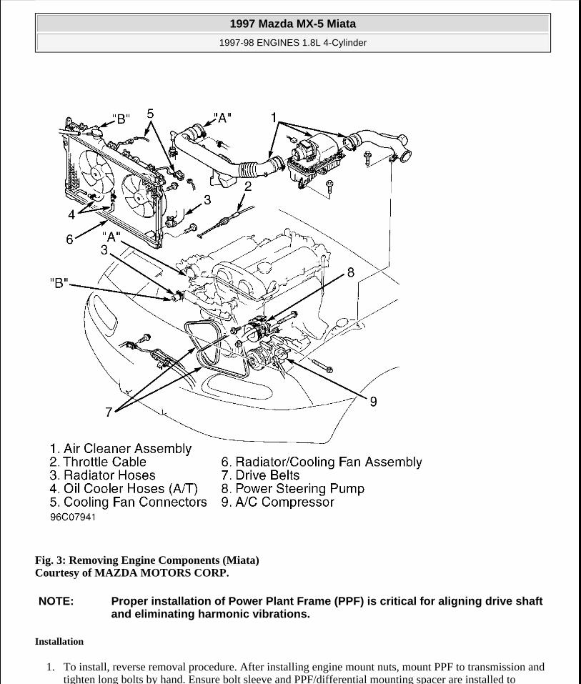
Fig. 3: Removing Engine Components (Miata) Courtesy of MAZDA MOTORS CORP.
Installation
1. To install, reverse removal procedure. After installing engine mount nuts, mount PPF to transmission and tighten long bolts by hand. Ensure bolt sleeve and PPF/differential mounting spacer are installed to
NOTE: Proper installation of Power Plant Frame (PPF) is critical for aligning drive shaft and eliminating harmonic vibrations.
1997 Mazda MX-5 Miata
1997-98 ENGINES 1.8L 4-Cylinder
Microsoft
Sunday, July 05, 2009 1:55:15 PM Page 5 © 2005 Mitchell Repair Information Company, LLC.

differential housing block.
2. Tighten PPF/differential mounting spacer bolts to 28-38 ft. lbs. (38-52 N.m). See Fig. 4 . Install PPF to differential. Hand-tighten long bolts. Ensure PPF-to-differential large shank reamer bolt and spacer are properly installed.
3. When PPF is properly aligned between transmission and differential, tighten all long mounting bolts to specification. Install rear transmission-to-PPF bracket and tighten to specification. See TORQUE SPECIFICATIONS . To complete installation, reverse removal procedure. Before installing M/T shift lever, add gear oil to transmission through shifter hole. Fill all fluids to correct level. Prime fuel system before attempting to start engine. See FUEL PRESSURE RELEASE & PRIMING. Bleed cooling system. See COOLING SYSTEM BLEEDING.
Fig. 4: Locating PPF-To-Differential Reamer Bolt, Sleeve & Spacer
NOTE: Reamer bolt is the front long bolt attaching PPF to differential. This bolt aligns PPF with drive train.
1997 Mazda MX-5 Miata
1997-98 ENGINES 1.8L 4-Cylinder
Microsoft
Sunday, July 05, 2009 1:55:15 PM Page 6 © 2005 Mitchell Repair Information Company, LLC.

Courtesy of MAZDA MOTORS CORP.
Removal & Installation (Protege)
1. Release residual pressure from fuel system. See FUEL PRESSURE RELEASE & PRIMING . Disconnect negative battery cable. Reference mark and remove hood. Raise vehicle. Remove engine undercover and side covers. See Fig. 5 . Drain engine, transaxle and cooling system fluids. Remove front wheels.
1997 Mazda MX-5 Miata
1997-98 ENGINES 1.8L 4-Cylinder
Microsoft
Sunday, July 05, 2009 1:55:15 PM Page 7 © 2005 Mitchell Repair Information Company, LLC.

Fig. 5: Removing Engine Components (Protege)Courtesy of MAZDA MOTORS CORP.
2. Lower vehicle. Remove air cleaner assembly. Remove battery/carrier assembly. Remove throttle cable and air intake duct across radiator (if equipped).
3. Remove all drive belts. DO NOT disconnect power steering hoses or A/C compressor hoses. Unbolt power steering pump and A/C compressor from engine, and wire aside.
4. Note locations and disconnect all necessary electrical connectors, ground wires, vacuum hoses, fuel hoses, coolant hoses and control cables for engine removal.
5. Plug all fuel hoses to avoid leakage. Attach engine support bar or engine hoist to secure engine. Raise vehicle. Disconnect exhaust manifold down pipe and exhaust brackets from engine. On A/T models, remove shift control cable.
6. On M/T models, remove shift control linkage and extension bar. Remove clutch release cylinder and fluid line bracket from transaxle housing, leaving fluid line connected to cylinder. Secure cylinder away from transaxle.
7. On all models, remove transmission wiring harness connectors and speedometer cable. Remove axle shaft nuts from hubs. Disconnect stabilizer bar from lower control arms. Separate lower ball joints and steering tie-rod ends from steering knuckles.
8. Pry axle shafts out of transaxle. Remove and discard circlip from axle shafts. For further information on axle shafts, see appropriate article in DRIVE AXLES.
9. Remove transaxle mount nuts from crossmember and loosen crossmember bolts. See Fig. 6 . Lower vehicle and attach engine hoist for engine removal. Remove engine front mount and transaxle top mount from inner fender panels. Remove transaxle crossmember. Remove engine and transaxle assembly from top of vehicle.
10. To install, reverse removal procedure. Tighten bolts and nuts to specifications. See TORQUE SPECIFICATIONS . Fill all fluids to correct level. Prime fuel system before attempting to start engine. See FUEL PRESSURE RELEASE & PRIMING . Bleed cooling system. See COOLING SYSTEM BLEEDING.
1997 Mazda MX-5 Miata
1997-98 ENGINES 1.8L 4-Cylinder
Microsoft
Sunday, July 05, 2009 1:55:15 PM Page 8 © 2005 Mitchell Repair Information Company, LLC.

Fig. 6: Removing Engine Mounts (Protege) Courtesy of MAZDA MOTORS CORP.
INTAKE MANIFOLD
Removal
1. Release residual pressure from fuel system. See FUEL PRESSURE RELEASE & PRIMING . Disconnect negative battery cable. Drain cooling system. Remove air cleaner assembly and ducting. See Fig. 3 or Fig. 5 . Mark and disconnect coolant hoses, vacuum hoses and electrical connectors from intake manifolds.
1997 Mazda MX-5 Miata
1997-98 ENGINES 1.8L 4-Cylinder
Microsoft
Sunday, July 05, 2009 1:55:15 PM Page 9 © 2005 Mitchell Repair Information Company, LLC.

2. Disconnect throttle cable. Remove fuel lines from fuel rail and pressure regulator. Remove throttle body intake duct housing and throttle body. Remove by-pass air control valve and solenoid valves. Remove upper intake manifold (if equipped).
3. Remove intake manifold support bracket from underneath manifold. Disconnect injector harness connectors, and remove injectors/fuel rail assembly. Remove intake manifold and gasket.
Installation
1. Ensure all gasket surfaces are clean and flat. Using NEW gasket, install intake manifold to cylinder head. Tighten manifold bolts/nuts evenly to specification, starting from center bolt and alternating outward. See TORQUE SPECIFICATIONS . Install support bracket underneath intake manifold.
2. Install gasket and upper intake manifold (if equipped). Tighten bolts/nuts evenly to specification, alternating from top to bottom. See TORQUE SPECIFICATIONS .
3. To complete installation, reverse removal procedure. Ensure throttle cable has .04-.12" (1-3 mm) free play. Ensure injectors twist freely and are not cocked in insulator "O" rings. Refill engine with coolant.
EXHAUST MANIFOLD
Removal & Installation
1. Remove air cleaner intake duct from top of radiator/fan assembly (if equipped). Disconnect oxygen sensor. Remove heat shields. Disconnect down pipe from exhaust manifold. Remove exhaust manifold.
2. To install, reverse removal procedure. Ensure all mating surfaces are clean and flat. Install NEW exhaust manifold gasket to cylinder head. Tighten manifold bolts evenly to specification, starting from center bolt and alternating outward. See TORQUE SPECIFICATIONS .
CYLINDER HEAD
Removal
1. Release residual pressure from fuel system. See FUEL PRESSURE RELEASE & PRIMING . Drain engine coolant. Note locations and disconnect all necessary electrical connectors, ground wires, vacuum hoses, fuel hoses, coolant hoses and control cables for cylinder head removal. Plug all fuel hoses to avoid leakage.
2. Remove spark plug wires from spark plugs. Remove all drive belts. Remove water pump pulley. Remove timing belt. See TIMING BELT . Remove camshaft/rocker cover.
3. Remove front exhaust pipe. Remove intake manifold support bracket. Loosen all cylinder head bolts evenly, in 3 steps, in reverse of tightening sequence. See Fig. 7 . Remove bolts and cylinder head assembly.
Inspection
Carefully clean carbon and gasket material from all mating surfaces. Clean threads of cylinder head bolts. Use a tap to clean threads in engine block. Check cylinder head for warpage. Resurface or replace head if it is not within specification. Check valve train components. Replace or resurface components if they are not within
1997 Mazda MX-5 Miata
1997-98 ENGINES 1.8L 4-Cylinder
Microsoft
Sunday, July 05, 2009 1:55:15 PM Page 10 © 2005 Mitchell Repair Information Company, LLC.

specification. See CYLINDER HEAD and VALVES & VALVE SPRINGS tables under ENGINE SPECIFICATIONS .
Installation
Install cylinder head gasket, cylinder head assembly and bolts. Tighten cylinder head bolts in 2 steps, and in sequence, to specification. See Fig. 7 . See TORQUE SPECIFICATIONS . To complete installation, reverse removal procedure.
Fig. 7: Cylinder Head Bolt Tightening Sequence Courtesy of MAZDA MOTORS CORP.
CRANKSHAFT FRONT SEAL
Removal
Disconnect negative battery cable. Remove drive belts and crankshaft pulley. Remove water pump pulley, timing belt covers and timing belt. See TIMING BELT . Use Crankshaft Lock Tool (49-D011-102) to lock crankshaft sprocket into position. Remove crankshaft sprocket bolt. Remove crankshaft sprocket using steering
1997 Mazda MX-5 Miata
1997-98 ENGINES 1.8L 4-Cylinder
Microsoft
Sunday, July 05, 2009 1:55:15 PM Page 11 © 2005 Mitchell Repair Information Company, LLC.
wheel puller. Pry out seal.
Installation
1. Apply light oil coat to seal lip. Using a hammer and seal installer, tap seal into oil pump body until it is flush with edge of pump body. DO NOT bottom seal in pump body. Align keyway slots, and install crankshaft sprocket and Woodruff key with tapered side toward oil pump body. Install crankshaft sprocket bolt.
2. Using Crankshaft Lock Tool (49-D011-102), lock crankshaft sprocket into position. Tighten lock bolt to specification. See TORQUE SPECIFICATIONS .
3. Install timing belt. See TIMING BELT under REMOVAL & INSTALLATION. Install timing belt covers, pulleys and drive belts. Reconnect negative battery cable and ensure timing is correct.
TIMING BELT
Removal (Miata)
1. Disconnect negative battery cable. Drain cooling system. Remove radiator hose and by-pass hoses from thermostat housing. Remove air cleaner intake duct assembly from between throttle body and air cleaner filter housing.
2. Remove drive belts and water pump pulley. Align crankshaft pulley timing mark with cylinder No. 1 at TDC of compression stroke. Hold crankshaft pulley stationary. Remove crankshaft pulley bolts and pulley. Remove crankshaft pulley hub bolt and hub.
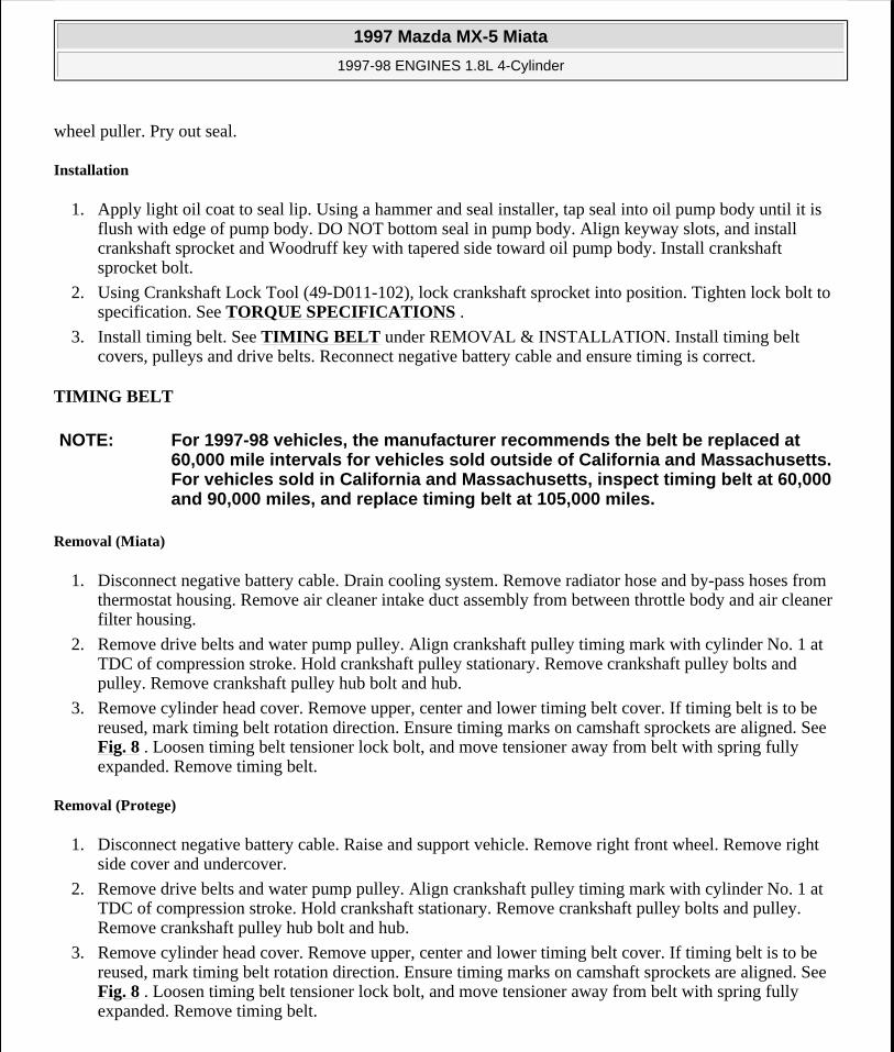
3. Remove cylinder head cover. Remove upper, center and lower timing belt cover. If timing belt is to be reused, mark timing belt rotation direction. Ensure timing marks on camshaft sprockets are aligned. See Fig. 8 . Loosen timing belt tensioner lock bolt, and move tensioner away from belt with spring fully expanded. Remove timing belt.
Removal (Protege)
1. Disconnect negative battery cable. Raise and support vehicle. Remove right front wheel. Remove right side cover and undercover.
2. Remove drive belts and water pump pulley. Align crankshaft pulley timing mark with cylinder No. 1 at TDC of compression stroke. Hold crankshaft stationary. Remove crankshaft pulley bolts and pulley. Remove crankshaft pulley hub bolt and hub.
3. Remove cylinder head cover. Remove upper, center and lower timing belt cover. If timing belt is to be reused, mark timing belt rotation direction. Ensure timing marks on camshaft sprockets are aligned. See Fig. 8 . Loosen timing belt tensioner lock bolt, and move tensioner away from belt with spring fully expanded. Remove timing belt.
NOTE: For 1997-98 vehicles, the manufacturer recommends the belt be replaced at 60,000 mile intervals for vehicles sold outside of California and Massachusetts. For vehicles sold in California and Massachusetts, inspect timing belt at 60,000 and 90,000 miles, and replace timing belt at 105,000 miles.
1997 Mazda MX-5 Miata
1997-98 ENGINES 1.8L 4-Cylinder
Microsoft
Sunday, July 05, 2009 1:55:15 PM Page 12 © 2005 Mitchell Repair Information Company, LLC.

Inspection (All Models)
Check timing belt for cracks, peeling, abrasion or other damage. Check tensioner bearing for looseness or roughness of rotation. Inspect tensioner spring for stretching. Replace parts as necessary.
Installation (All Models)
1. Position notch on crankshaft sprocket to 12 o'clock position (aligned with mark on oil pump). Align timing marks on camshaft sprockets. See Fig. 8 . Ensure crankshaft timing mark is at TDC. Install belt around crankshaft sprocket, then working in a counterclockwise direction, route belt around camshaft sprockets.
2. Loosen timing belt tensioner lock bolt and allow spring to apply tension on belt. Snug tensioner lock bolt. Rotate crankshaft 2 complete turns in direction of normal engine rotation. Ensure timing marks align. If timing marks are not aligned, remove belt, realign all timing marks, and repeat installation procedure.
3. Check timing belt deflection with 22 lbs. (10 kg) of pressure applied to belt. See Fig. 9 . Ensure timing belt deflection is within specification. See TIMING BELT DEFLECTION .
TIMING BELT DEFLECTION
Application (1) Deflection In. (mm)Miata & Protege .35-.45 (9.0-11.5)(1) Deflection measurement is with 22 lbs. (10 kg) of pressure applied to timing belt. See Fig. 9 .
1997 Mazda MX-5 Miata
1997-98 ENGINES 1.8L 4-Cylinder
Microsoft
Sunday, July 05, 2009 1:55:15 PM Page 13 © 2005 Mitchell Repair Information Company, LLC.

Fig. 8: Aligning Camshaft Timing Marks Courtesy of MAZDA MOTORS CORP.
1997 Mazda MX-5 Miata
1997-98 ENGINES 1.8L 4-Cylinder
Microsoft
Sunday, July 05, 2009 1:55:15 PM Page 14 © 2005 Mitchell Repair Information Company, LLC.

Fig. 9: Measuring Timing Belt Deflection Courtesy of MAZDA MOTORS CORP.
HYDRAULIC LASH ADJUSTER (HLA)
Removal
Disconnect negative battery cable. Remove camshaft. See CAMSHAFT . Mark location of each HLA for reassembly reference. Remove HLA from cylinder head.
Inspection
Place HLA in palm of hand. Attempt to compress HLA plunger with thumb. If plunger compresses, replace HLA.
NOTE: If hydraulic lash adjusters are persistently noisy, check with manufacturer for availability of modified adjusters.
1997 Mazda MX-5 Miata
1997-98 ENGINES 1.8L 4-Cylinder
Microsoft
Sunday, July 05, 2009 1:55:15 PM Page 15 © 2005 Mitchell Repair Information Company, LLC.

Installation
Insert HLA in original location. To complete installation, reverse removal procedure. Tighten camshaft bearing caps evenly in sequence to specification. See Fig. 10 or Fig. 11 . See TORQUE SPECIFICATIONS .
CAMSHAFT
Removal
Remove cylinder head cover. Remove timing belt. See TIMING BELT . Remove distributor/camshaft position sensor. Reference mark camshafts, caps and sprockets, and remove sprockets. Loosen camshaft bearing cap bolts evenly in 5-6 steps, in sequence. See Fig. 10 or Fig. 11 . Remove camshafts.
Inspection
Check camshaft end play. Check camshaft journal diameters and bearing clearances. Check camshaft lobes for wear. See CAMSHAFT under ENGINE SPECIFICATIONS. If any measurement is not within specification, replace camshaft and/or cylinder head.
Installation
To install, reverse removal procedure. On both camshafts, apply small amount of silicone sealant to contact area of cylinder head/camshaft seal cover cap. Tighten camshaft bearing cap bolts evenly in sequence to specification. See Fig. 10 or Fig. 11 . See TORQUE SPECIFICATIONS .
NOTE: On Miata, exhaust camshaft has a slot for camshaft position sensor drive. On Protege, exhaust camshaft has a slot for distributor drive. On all models, match mark camshafts and sprockets for installation reference.
1997 Mazda MX-5 Miata
1997-98 ENGINES 1.8L 4-Cylinder
Microsoft
Sunday, July 05, 2009 1:55:15 PM Page 16 © 2005 Mitchell Repair Information Company, LLC.

Fig. 10: Camshaft Bearing Cap Bolt Removal & Installation Sequence (Miata) Removal Courtesy of MAZDA MOTORS CORP.
1997 Mazda MX-5 Miata
1997-98 ENGINES 1.8L 4-Cylinder
Microsoft
Sunday, July 05, 2009 1:55:15 PM Page 17 © 2005 Mitchell Repair Information Company, LLC.

Fig. 11: Camshaft Bearing Cap Bolt Removal & Installation Sequence (Miata) Installation Courtesy of MAZDA MOTORS CORP.
1997 Mazda MX-5 Miata
1997-98 ENGINES 1.8L 4-Cylinder
Microsoft
Sunday, July 05, 2009 1:55:15 PM Page 18 © 2005 Mitchell Repair Information Company, LLC.

Fig. 12: Camshaft Bearing Cap Bolt Removal & Installation Sequence (Protege) Removal Courtesy of MAZDA MOTORS CORP.
1997 Mazda MX-5 Miata
1997-98 ENGINES 1.8L 4-Cylinder
Microsoft
Sunday, July 05, 2009 1:55:15 PM Page 19 © 2005 Mitchell Repair Information Company, LLC.
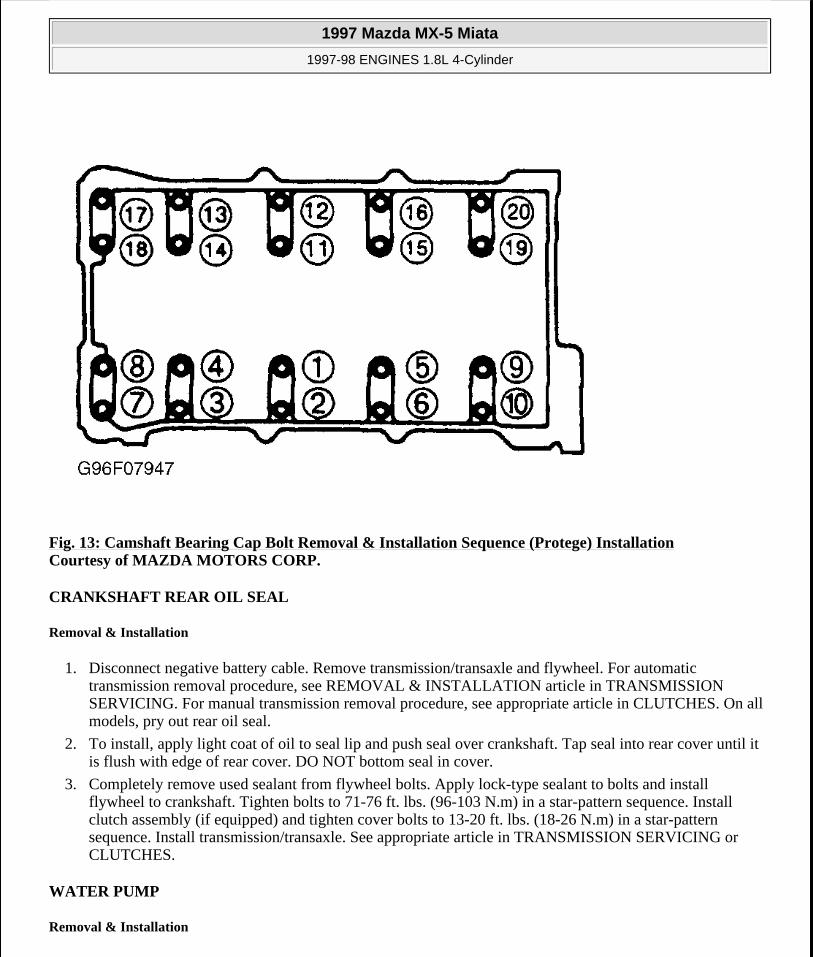
Fig. 13: Camshaft Bearing Cap Bolt Removal & Installation Sequence (Protege) Installation Courtesy of MAZDA MOTORS CORP.
CRANKSHAFT REAR OIL SEAL
Removal & Installation
1. Disconnect negative battery cable. Remove transmission/transaxle and flywheel. For automatic transmission removal procedure, see REMOVAL & INSTALLATION article in TRANSMISSION SERVICING. For manual transmission removal procedure, see appropriate article in CLUTCHES. On all models, pry out rear oil seal.
2. To install, apply light coat of oil to seal lip and push seal over crankshaft. Tap seal into rear cover until it is flush with edge of rear cover. DO NOT bottom seal in cover.
3. Completely remove used sealant from flywheel bolts. Apply lock-type sealant to bolts and install flywheel to crankshaft. Tighten bolts to 71-76 ft. lbs. (96-103 N.m) in a star-pattern sequence. Install clutch assembly (if equipped) and tighten cover bolts to 13-20 ft. lbs. (18-26 N.m) in a star-pattern sequence. Install transmission/transaxle. See appropriate article in TRANSMISSION SERVICING or CLUTCHES.
WATER PUMP
Removal & Installation
1997 Mazda MX-5 Miata
1997-98 ENGINES 1.8L 4-Cylinder
Microsoft
Sunday, July 05, 2009 1:55:15 PM Page 20 © 2005 Mitchell Repair Information Company, LLC.

1. Drain engine coolant. Disconnect battery cable. Position No. 1 cylinder at TDC of compression stroke. On Protege, remove right side cover and undercover.
2. On Miata, remove air cleaner intake duct from between throttle body and air cleaner/filter assembly. On all models, remove upper radiator hose and by-pass hoses from thermostat housing.
3. Remove drive belts and water pump pulley. Remove power steering pump with hoses attached and secure pump away from engine (if necessary). Remove timing belt, tensioner and idler. See TIMING BELT.
4. Unbolt water inlet pipe from water pump. Water pump inlet pipe has lower radiator hose and by-pass pipe attached to it. Remove bolts from water pump. To install, reverse removal procedure. Tighten bolt to specification. See TORQUE SPECIFICATIONS .
OIL PAN
Removal & Installation (Miata)
1. Disconnect negative battery cable. Drain engine oil. Remove dipstick, tube and "O" ring. Raise vehicle on hoist. Remove engine undercover. Disconnect steering column shaft at steering rack coupling. See Fig. 14 . Remove engine mount nuts. Lift and support engine using jack.
2. Support crossmember using transmission jack and remove crossmember bolts. Slowly and carefully lower crossmember until clearance between oil pan and steering rack is about 4 inches. Remove oil pan bolts from engine block and transmission.
3. DO NOT damage sealant contact surfaces. Remove oil pan by prying between oil pan and transmission support. Remove oil pan baffle by prying it from engine. See Fig. 14 . DO NOT deform oil pan baffle. Replace oil pan baffle if deformed. Clean sealant from oil pan, bolts, engine block and both sides of oil pan baffle.
4. To install, apply oil resistant sealant to engine block and oil pan. Install oil pan baffle and oil pan within 5 minutes of applying sealant. To complete installation, reverse removal procedure. Tighten bolts to specification. See TORQUE SPECIFICATIONS . Fill engine with oil to specification. See ENGINE LUBRICATION SYSTEM under ENGINE OILING.
NOTE: For further information on cooling systems, see SPECIFICATIONS & ELECTRIC COOLING FANS article in ENGINE COOLING.
NOTE: On Miata, engine must be supported in order to remove oil pan.
1997 Mazda MX-5 Miata
1997-98 ENGINES 1.8L 4-Cylinder
Microsoft
Sunday, July 05, 2009 1:55:15 PM Page 21 © 2005 Mitchell Repair Information Company, LLC.
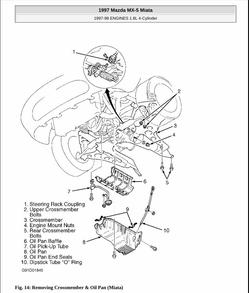
Fig. 14: Removing Crossmember & Oil Pan (Miata)
1997 Mazda MX-5 Miata
1997-98 ENGINES 1.8L 4-Cylinder
Microsoft
Sunday, July 05, 2009 1:55:15 PM Page 22 © 2005 Mitchell Repair Information Company, LLC.

Courtesy of MAZDA MOTORS CORP.
Removal & Installation (Protege)
1. Disconnect negative battery cable. Remove engine undercovers. Drain engine oil. Remove exhaust header downpipe and brackets from front exhaust system. Remove oil pan retaining bolts.
2. DO NOT damage sealant contact surfaces. Remove oil pan by prying between oil pan and mounting surface. On Protege, remove stiffener by prying between stiffener and cylinder block. On all models, clean all sealant from oil pan, bolts, engine block and both sides of stiffener (Protege).
3. On Protege, apply oil resistant sealant to engine block and stiffener. Install stiffener. On all models, apply sealant and install oil pan within 5 minutes of applying sealant. To complete installation, reverse removal procedure. Tighten all bolts to specification. See TORQUE SPECIFICATIONS . Fill engine with oil to specification. See ENGINE LUBRICATION SYSTEM under ENGINE OILING.
OVERHAUL
CYLINDER HEAD
Cylinder Head
Clean carbon and gasket material from all mating surfaces. Using a tap, clean cylinder head threads. Check cylinder head warpage. If warpage exceeds specification, resurface head, but DO NOT exceed grinding limit. See CYLINDER HEAD under ENGINE SPECIFICATIONS. After resurfacing cylinder head, check cylinder head height. Replace cylinder head if height is less than minimum specification.
Valve Springs
Ensure valve spring free length, out-of-square and compressed length are within specification. See VALVES & VALVE SPRINGS under ENGINE SPECIFICATIONS. Replace valve spring if necessary.
Valve Stem Oil Seals
1. On Miata, use Installer Set (49-L012-0A0) to install valve seals. See Fig. 15 . Adjust installer dimension "L" to seal depth of .720-.744" (18.3-18.9 mm). Using hand pressure ONLY, install seal until it contacts cylinder head. Lightly oil valve seal lip.
2. On Protege, use Installer Set (49-L012-0A0) to install valve seals. See Fig. 15 . Adjust installer dimension "L" to seal depth of .783" (19.9 mm). Using hand pressure, install seal until it contacts cylinder
CAUTION: If reusing old oil pan bolts, remove old sealant from bolt threads. Failure to remove old sealant may result in cracked block at bolt holes.
NOTE: Intake and exhaust valve stem seals are different. Exhaust seals can be identified by ridges molded into top of seal. Intake seals do not have identifying ridges. Incorrect installation of valve stem seals will cause premature failure.
1997 Mazda MX-5 Miata
1997-98 ENGINES 1.8L 4-Cylinder
Microsoft
Sunday, July 05, 2009 1:55:15 PM Page 23 © 2005 Mitchell Repair Information Company, LLC.

head. Lightly oil valve seal lip.
Fig. 15: Installing Valve Guide Seals Courtesy of MAZDA MOTORS CORP.
Valve Guides
1. Check valve stem-to-valve guide oil clearance. Ensure valve guide inside diameter is within specification. See CYLINDER HEAD under ENGINE SPECIFICATIONS.
2. Completely disassemble cylinder head. Gradually heat cylinder head in water to 194°F (94°C). Using Valve Guide Remover (49-B012-005), drive valve guide out, working from combustion chamber side of cylinder head. Repeat procedure if required, keeping cylinder head hot so aluminum head will not warp.
3. If required, install new circlip on guide. Using proper components of Valve Guide Installer (49-L012-0A0), adjust installer guide depth (dimension "L") to specification using depth micrometer or caliper. See VALVE GUIDE INSTALLED HEIGHT . See Fig. 16 .
4. Insert guide into pre-adjusted installer and drive guide into cylinder head from camshaft side until guide circlip, and/or installer contact cylinder head. Measure dimension "L" (guide installed height). See Fig. 16 or Fig. 15 . If installed height is not within specification, adjust or replace valve guide or cylinder head as necessary. See VALVE GUIDE INSTALLED HEIGHT .
NOTE: On Miata, use only NEW exhaust valve guides to replace intake or exhaust valve guides.
1997 Mazda MX-5 Miata
1997-98 ENGINES 1.8L 4-Cylinder
Microsoft
Sunday, July 05, 2009 1:55:15 PM Page 24 © 2005 Mitchell Repair Information Company, LLC.

VALVE GUIDE INSTALLED HEIGHT
Fig. 16: Adjusting Valve Guide Installer & Installing Guide Courtesy of MAZDA MOTORS CORP.
Application In. (mm)Miata & Protege .720-.744 (18.30-18.90)
1997 Mazda MX-5 Miata
1997-98 ENGINES 1.8L 4-Cylinder
Microsoft
Sunday, July 05, 2009 1:55:15 PM Page 25 © 2005 Mitchell Repair Information Company, LLC.

Fig. 17: Measuring Installed Valve & Guide Height Courtesy of MAZDA MOTORS CORP.
Valve Seat
1. Service valve guide before valve seat. Valve seat replacement information is not available from manufacturer. Inspect valve seat for roughness and damage. Check valve seat angle and seat width.
2. Measure seat contact width on valve and ensure seat contact position is in center of valve face. Service seat if angle and width are not within specification. See CYLINDER HEAD under ENGINE SPECIFICATIONS. Measure valve installed height after servicing valve seat. See Fig. 17 . See VALVE INSTALLED HEIGHT .
3. If valve installed height is within serviceable range, install adjusting shim on spring seat. If installed height exceeds serviceable range, replace cylinder head.
VALVE INSTALLED HEIGHT Application In. (mm)Miata & Protege
1997 Mazda MX-5 Miata
1997-98 ENGINES 1.8L 4-Cylinder
Microsoft
Sunday, July 05, 2009 1:55:15 PM Page 26 © 2005 Mitchell Repair Information Company, LLC.

Valves
Check valve face angle, head diameter, margin thickness and stem diameter. Service or replace valves if measurements are not within specifications. See VALVES & VALVE SPRINGS under ENGINE SPECIFICATIONS.
Valve Seat Correction Angles
Measure seat contact width on valve. See VALVE SEAT. If seat width is not within specification or if valve face does not contact center of valve seat, correct seat using a 70-degree grinding stone. After correcting seat, lightly finish seat with 45-degree grinding stone.
VALVE TRAIN
Hydraulic Lash Adjusters
1. Remove camshaft cover. Check movement of each Hydraulic Lash Adjuster (HLA) by pushing downward using hand pressure only. If HLA compresses, replace HLA. To remove HLA, remove camshafts. See CAMSHAFT under REMOVAL & INSTALLATION. Mark location of HLA before removing from bore. Lift HLA from cylinder head.
2. Inspect HLA friction surfaces for wear and damage. Replace HLA if required. Coat HLA with engine oil and install in original location. Ensure HLA moves smoothly in bore by using small magnet attached to HLA.
CYLINDER BLOCK ASSEMBLY
Piston & Connecting Rod Assembly
1. Before removing rod cap from crankshaft, measure and record rod side play. See CONNECTING RODSunder ENGINE SPECIFICATIONS. Before removing connecting rods, measure and record connecting rod bearing oil clearance. See CRANKSHAFT, MAIN & CONNECTING ROD BEARINGS under ENGINE SPECIFICATIONS.
2. Before separating piston from connecting rod, mark piston in relation to connecting rod. Check oscillation movement of piston and rod assembly (hold piston horizontally, lift rod and allow rod to drop by its own weight). If pin binds in pin bore (rod does not drop), replace piston and/or pin as necessary.
3. To separate components, press piston pin out of piston and rod assembly, noting pressure required to
Normal 1.772-1.791 (45.00-45.50)Serviceable 1.733-1.772 (45.60-46.50)
NOTE: If hydraulic lash adjusters are persistently noisy, check with manufacturer for availability of modified adjusters.
NOTE: During disassembly, match mark components for reassembly reference.
1997 Mazda MX-5 Miata
1997-98 ENGINES 1.8L 4-Cylinder
Microsoft
Sunday, July 05, 2009 1:55:15 PM Page 27 © 2005 Mitchell Repair Information Company, LLC.

remove piston pin. If piston pin can be pressed out with less than 1100 lbs. (500 kg) of pressure, replace piston and/or connecting rod.
4. Ensure piston pin diameter, piston fit and rod fit are within specification. See PISTONS, PINS & RINGS under ENGINE SPECIFICATIONS. Using 1100-3300 lbs. (500-1500 kg) of pressure, install piston pin through side of piston that has an "F" mark near pin bore. See Fig. 18 . Install piston and rod assembly so "F" mark on side of piston is facing front of engine.
Fig. 18: Installing Piston & Connecting Rod Assembly Courtesy of MAZDA MOTORS CORP.
1997 Mazda MX-5 Miata
1997-98 ENGINES 1.8L 4-Cylinder
Microsoft
Sunday, July 05, 2009 1:55:15 PM Page 28 © 2005 Mitchell Repair Information Company, LLC.

Fitting Pistons
1. Ensure pistons are not scored or damaged. Measure piston diameter on piston skirt at 90-degree angle from piston pin, .65" (16.5 mm) below lowest ring groove. See PISTONS, PINS & RINGS under ENGINE SPECIFICATIONS.
2. Check piston-to-cylinder wall clearance in 3 different vertical places of piston travel. If clearance is not within specification, re-bore cylinders to fit oversize pistons. Using NEW piston rings, measure piston ring side clearance around entire piston circumference. If clearance is not within specification, replace piston. See PISTONS, PINS & RINGS .
Piston Rings
1. If ring end gap and side clearance are not within specification, replace piston and/or rings as necessary. See PISTONS, PINS & RINGS under ENGINE SPECIFICATIONS.
2. Install oil ring spacer. Ensure ends DO NOT overlap. See Fig. 19 . Upper and lower rails are the same and are interchangeable. In stall rails, ensuring rails are expanded by spacer tangs (oil rings when assembled should rotate freely). Install rings No. 1 (top) and No. 2 (second) with "R" mark toward top of piston. Ensure ring end gaps are properly positioned around piston. See Fig. 20 .
Fig. 19: Identifying Oil Rings
NOTE: Pistons and rings are available in .010" (.25 mm) and .020" (.50 mm) oversize.
1997 Mazda MX-5 Miata
1997-98 ENGINES 1.8L 4-Cylinder
Microsoft
Sunday, July 05, 2009 1:55:15 PM Page 29 © 2005 Mitchell Repair Information Company, LLC.

Courtesy of MAZDA MOTORS CORP.
Fig. 20: Identifying Piston Rings & Positioning Ring End Gaps Courtesy of MAZDA MOTORS CORP.
Crankshaft & Main Bearings
1. Check crankshaft connecting rod journals for wear, out-of-round, taper and undersize. Machine or replace crankshaft and/or bearings as necessary. See CRANKSHAFT, MAIN & CONNECTING ROD BEARINGS under ENGINE SPECIFICATIONS.
2. Before removing main cap, measure and record crankshaft end play by prying crankshaft forward, then rearward. Using Plastigage method, measure and record main bearing oil clearance. Remove crankshaft. Measure and record each main journal diameter in 2 places. See CRANKSHAFT, MAIN & CONNECTING ROD BEARINGS under ENGINE SPECIFICATIONS.
1997 Mazda MX-5 Miata
1997-98 ENGINES 1.8L 4-Cylinder
Microsoft
Sunday, July 05, 2009 1:55:15 PM Page 30 © 2005 Mitchell Repair Information Company, LLC.

3. Install main bearing caps with square mark facing front of engine. Tighten main bearing cap bolts in 2-3 step, working outward from center bearing. Tighten bolts to specification. See TORQUE SPECIFICATIONS . Thrust Bearing - Install thrust bearing before installing crankshaft. Check crankshaft end play with crankshaft bearings and caps installed, but without connecting rods attached to crankshaft. DO NOT turn crankshaft until bearings are lubricated. If crankshaft end play exceeds specification, grind crankshaft and replace thrust bearings with oversize thrust bearings, or replace crankshaft and thrust bearings. See CRANKSHAFT, MAIN & CONNECTING ROD BEARINGS under ENGINE SPECIFICATIONS.
Cylinder Block
Check cylinder bore out-of-round, taper, ridge and piston-to-cylinder bore clearance. Check head gasket surface for warpage. If warpage is not within specification, machine or replace cylinder block as necessary. See CYLINDER BLOCK under ENGINE SPECIFICATIONS. Remove, clean and install oil jets for piston oil spraying.
ENGINE OILING
ENGINE LUBRICATION SYSTEM
NOTE: See cross-sectional view of engine oil circuit. See Fig. 21 .
1997 Mazda MX-5 Miata
1997-98 ENGINES 1.8L 4-Cylinder
Microsoft
Sunday, July 05, 2009 1:55:15 PM Page 31 © 2005 Mitchell Repair Information Company, LLC.
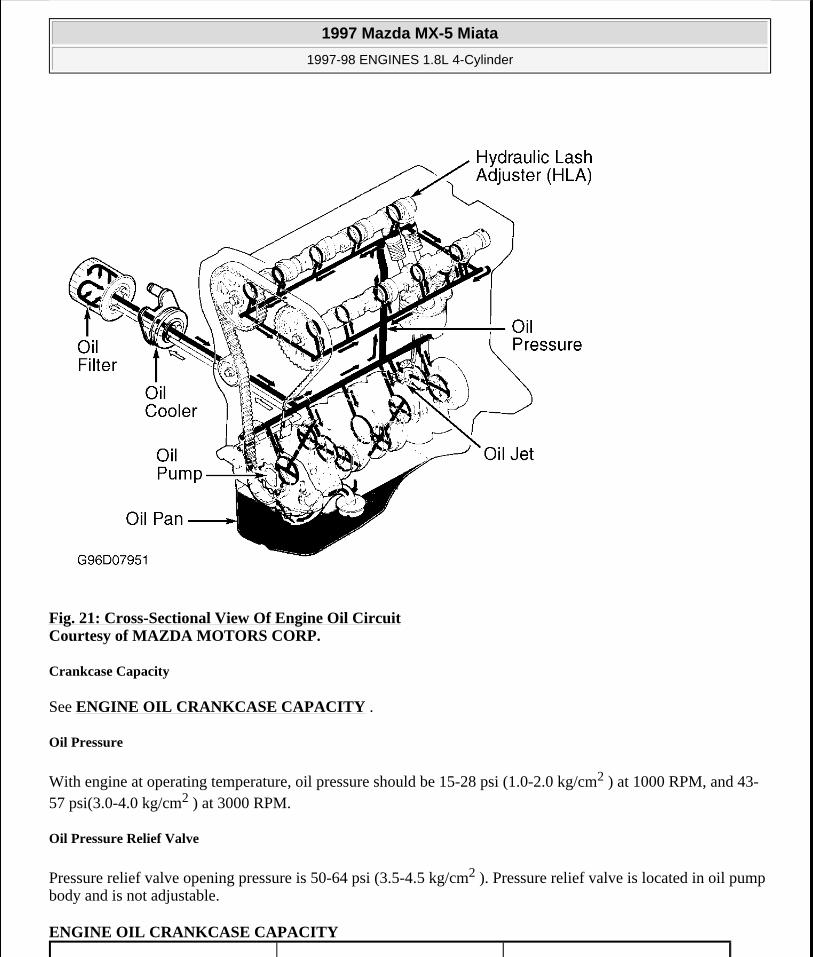
Fig. 21: Cross-Sectional View Of Engine Oil Circuit Courtesy of MAZDA MOTORS CORP.
Crankcase Capacity
See ENGINE OIL CRANKCASE CAPACITY .
Oil Pressure
With engine at operating temperature, oil pressure should be 15-28 psi (1.0-2.0 kg/cm2 ) at 1000 RPM, and 43-57 psi(3.0-4.0 kg/cm2 ) at 3000 RPM.
Oil Pressure Relief Valve
Pressure relief valve opening pressure is 50-64 psi (3.5-4.5 kg/cm2 ). Pressure relief valve is located in oil pump body and is not adjustable.
ENGINE OIL CRANKCASE CAPACITY
1997 Mazda MX-5 Miata
1997-98 ENGINES 1.8L 4-Cylinder
Microsoft
Sunday, July 05, 2009 1:55:15 PM Page 32 © 2005 Mitchell Repair Information Company, LLC.

OIL PUMP
Removal & Disassembly
1. Disconnect negative battery cable. Remove dipstick, tube and "O" ring. Drain engine oil and coolant. Remove drive belts, crankshaft and water pump pulleys. Remove generator, A/C compressor and mounting bracket. Without disconnecting A/C hoses, secure A/C compressor away from engine. Remove timing belt and related components. See TIMING BELT under REMOVAL & INSTALLATION.
2. Hold crankshaft sprocket in place and remove crankshaft sprocket bolt. Remove crankshaft sprocket using steering wheel puller. Leave crankshaft Woodruff key in place.
3. Remove oil pan and oil pump pick-up tube. See OIL PAN under REMOVAL & INSTALLATION. Remove oil pump housing assembly. Using a screwdriver protected with a rag, drive oil seal out from inside of oil pump housing assembly.
4. Remove pump cover screws (use a manual impact screwdriver, if necessary). See Fig. 22 . Remove pump cover. Note location of alignment marks on inner and outer rotors. Remove inner and outer rotors. To remove pressure relief valve, remove spring seat, pressure spring and control plunger.
Inspection
Replace pressure relief valve spring if length is not as specified. See OIL PUMP SPECIFICATIONS . Ensure plunger slides freely in bore. Replace oil pump housing assembly if clearances are not as specified. See OIL PUMP SPECIFICATIONS .
Reassembly & Installation
1. Apply oil to friction surfaces. Install inner and outer rotors with marks aligned. See Fig. 23 . Install pressure relief valve components. Apply oil to lip of NEW oil seal. Press oil seal into bore until even with face of oil pump housing assembly.
2. Install pump cover. Tighten screws to 53-78 INCH lbs. (6-9 N.m). To complete installation, reverse removal procedure. Tighten bolts to specification. See TORQUE SPECIFICATIONS .
OIL PUMP SPECIFICATIONS
Application W/O Filter Qts. (L) W/Filter Qts. (L)Miata & Protege 3.8 (3.6) 4.0 (3.8)
Application Maximum Clearance In. (mm)
Maximum Rotor Tip Clearance (1) .0079 (.20)
Maximum Rotor-To-Pump Body Clearance (2) .0079 (.20)
Maximum Rotor Side Clearance (3) .0055 (.14)
Pressure Relief Spring Free Length 1.809 (45.94)(1) See Fig. 23 .
(2) Insert feeler gauge between outer rotor and pump body.
Place straightedge across pump body and check clearance between straightedge and both rotors.
1997 Mazda MX-5 Miata
1997-98 ENGINES 1.8L 4-Cylinder
Microsoft
Sunday, July 05, 2009 1:55:15 PM Page 33 © 2005 Mitchell Repair Information Company, LLC.
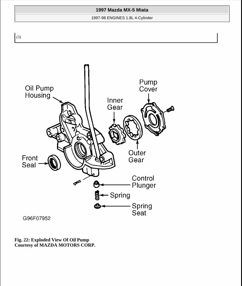
Fig. 22: Exploded View Of Oil Pump Courtesy of MAZDA MOTORS CORP.
(3)
1997 Mazda MX-5 Miata
1997-98 ENGINES 1.8L 4-Cylinder
Microsoft
Sunday, July 05, 2009 1:55:15 PM Page 34 © 2005 Mitchell Repair Information Company, LLC.

Fig. 23: Aligning Marks On Inner & Outer Rotor Courtesy of MAZDA MOTORS CORP.
TORQUE SPECIFICATIONS
TORQUE SPECIFICATIONS Application Ft. Lbs. (N.m)Axle Shaft Nut (Protege) 174-235 (235-319)Camshaft Sprocket Bolt 36-45 (49-61)Compressor Bracket-To-Engine Bolt 28-38 (38-51)Connecting Rod Cap Nut 35-37 (48-50)Crankshaft Pulley Bolts 9-13 (12-18)Crankshaft/Timing Belt Sprocket Bolt 116-123 (157-167)Crossmember-To-Frame Bolt 47-66 (63-89)
Cylinder Head Bolt (2) 56-60 (76-81)
Distributor Bolt 14-19 (19-26)Drive Shaft Bolts (Miata) 37-43 (50-58)Engine Mount Nut 42-58 (57-79)Engine Mount-To-Engine Bolt 27-40 (37-54)Engine Mount-To-Frame Nut
Miata 42-57 (57-77)Protege 28-38 (38-51)
Exhaust Header Pipe-To-Exhaust
1997 Mazda MX-5 Miata
1997-98 ENGINES 1.8L 4-Cylinder
Microsoft
Sunday, July 05, 2009 1:55:15 PM Page 35 © 2005 Mitchell Repair Information Company, LLC.

ENGINE SPECIFICATIONS
GENERAL SPECIFICATIONS
Manifold Nut 23-34 (31-46)Exhaust Manifold Nut (1) 28-34 (38-46)Flywheel Bolt 71-76 (96-103)Fuel Rail Bolt 14-19 (19-26)Generator Top Bolt 27-38 (37-51)Intake Manifold Bolt/Nut (1) 14-19 (19-26)Intake Manifold Support Bracket 14-18 (19-25)Main Bearing Cap Bolt
Step 1 (1) 22-27 (30-37)Step 2 (Final) (1) 40-43 (54-58)
Oil Pan-To-Transaxle Bolt (Protege) 28-38 (38-51)Oil Pan-To-Transmission Bolt (Miata) 48-65 (64-88)Oil Pump-To-Block Bolt 14-19 (19-26)Power Steering Pump-To-Bracket Bolt 28-38 (38-51)
PPF/Differential Spacer Mounting Bolt (2) 27-38 (37-51)
PPF-To-Differential Long Mounting Bolt (2) 77-91 (104-123)
PPF-To-Transmission Side Mounting Bolt (2) 77-91 (104-123)
PPF/Transmission Rear Bracket Mounting Bolt 27-40 (37-54)Spark Plug 11-16 (15-22)Timing Belt Tensioner Bolt 27-38 (37-51)Water Pump Bolt 14-19 (19-26)
INCH Lbs. (N.m)Camshaft Bearing Cap Bolt (3) 100-125 (11.3-14.1)Cylinder Head Cover Bolt 43-78 (5-9)Oil Jet 104-156 (12-18)Oil Pan-To-Engine Block Bolt
(Miata & Protege) 70-95 (8-11)Oil Pump Cover Screws 53-78 (6-9)Oil Strainer Bolt 70-95 (8-11)Rear Cover Bolt 70-95 (8-11)Water Pump Pulley Bolt 70-95 (8-11)(1) Tighten evenly to specification in alternating sequence.
(2) Tighten in sequence. See Fig. 7 .
(3) Tighten in sequence. See Fig. 10 or Fig. 11 .
1997 Mazda MX-5 Miata
1997-98 ENGINES 1.8L 4-Cylinder
Microsoft
Sunday, July 05, 2009 1:55:15 PM Page 36 © 2005 Mitchell Repair Information Company, LLC.
CRANKSHAFT, MAIN & CONNECTING ROD BEARINGS
CRANKSHAFT, MAIN & CONNECTING ROD BEARINGS
CONNECTING RODS
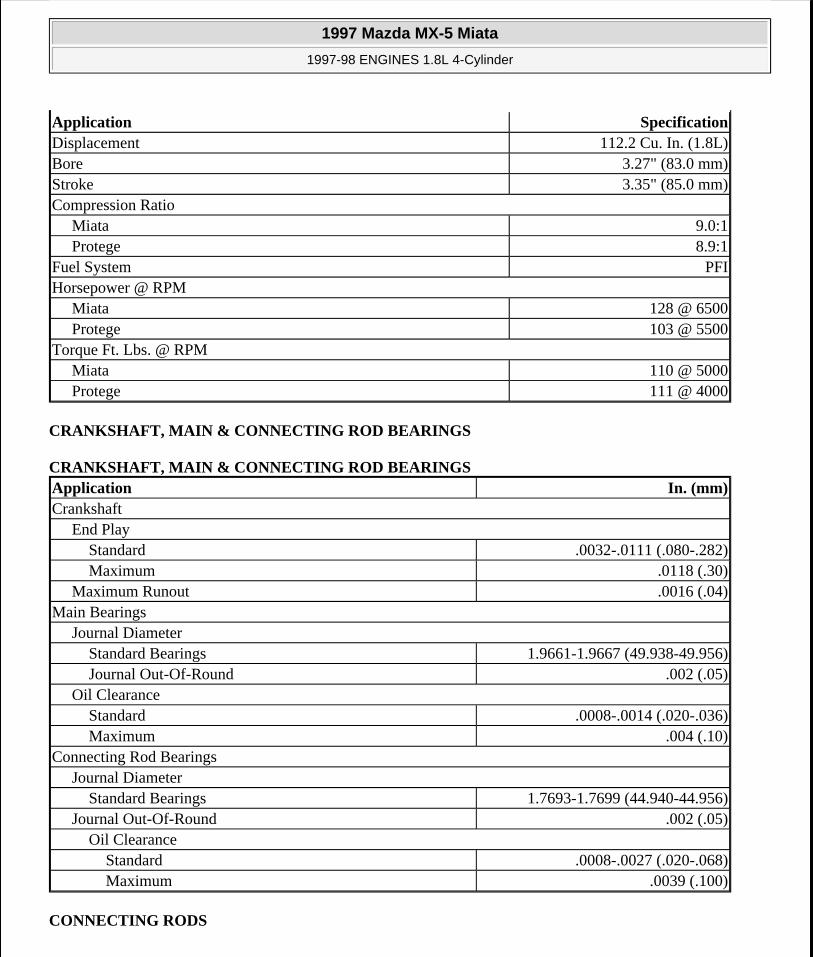
Application SpecificationDisplacement 112.2 Cu. In. (1.8L)Bore 3.27" (83.0 mm)Stroke 3.35" (85.0 mm)Compression Ratio
Miata 9.0:1Protege 8.9:1
Fuel System PFIHorsepower @ RPM
Miata 128 @ 6500Protege 103 @ 5500
Torque Ft. Lbs. @ RPMMiata 110 @ 5000Protege 111 @ 4000
Application In. (mm)Crankshaft
End PlayStandard .0032-.0111 (.080-.282)Maximum .0118 (.30)
Maximum Runout .0016 (.04)Main Bearings
Journal DiameterStandard Bearings 1.9661-1.9667 (49.938-49.956)Journal Out-Of-Round .002 (.05)
Oil ClearanceStandard .0008-.0014 (.020-.036)Maximum .004 (.10)
Connecting Rod BearingsJournal Diameter
Standard Bearings 1.7693-1.7699 (44.940-44.956)Journal Out-Of-Round .002 (.05)
Oil ClearanceStandard .0008-.0027 (.020-.068)Maximum .0039 (.100)
1997 Mazda MX-5 Miata
1997-98 ENGINES 1.8L 4-Cylinder
Microsoft
Sunday, July 05, 2009 1:55:15 PM Page 37 © 2005 Mitchell Repair Information Company, LLC.

CONNECTING RODS
PISTONS, PINS & RINGS
PISTONS, PINS & RINGS
Application In. (mm)Bore Diameter
Crankpin Bore 1.8898-1.8904 (48.000-48.016)
Pin Bore .7876-.7879 (20.003-20.014)Center-To-Center Length 5.231-5.234 (132.85-132.95)Maximum Bend (1)
Side PlayStandard .0044-.0103 (.110-.262)Maximum .012 (.30)
(1) Bend must not exceed .003" per 1.97" (.075 mm per 50 mm).
Application In. (mm)Pistons
ClearanceStandard
Miata .0013-.0023 (.032-.059)Protege .0010-.0014 (.024-.037)
Maximum .006 (.15)Diameter
Standard 3.2660-3.2666 (82.954-82.974)Oversize
.010" (0.25 mm) 3.2761-3.2762 (83.211-83.217)
.020" (0.50 mm) 3.2859-3.2860 (83.461-83.467)
PinsDiameter .7869-.7871 (19.987-19.993)Piston Fit -.0002-.0005 (-.005-.013)
RingsNo. 1
End GapStandard .006-.011 (.15-.30)Maximum .039 (1.0)
Side ClearanceStandard .0012-.0025 (.030-.065)Maximum .006 (.15)
1997 Mazda MX-5 Miata
1997-98 ENGINES 1.8L 4-Cylinder
Microsoft
Sunday, July 05, 2009 1:55:15 PM Page 38 © 2005 Mitchell Repair Information Company, LLC.
CYLINDER BLOCK
CYLINDER BLOCK
CYLINDER HEAD
CYLINDER HEAD
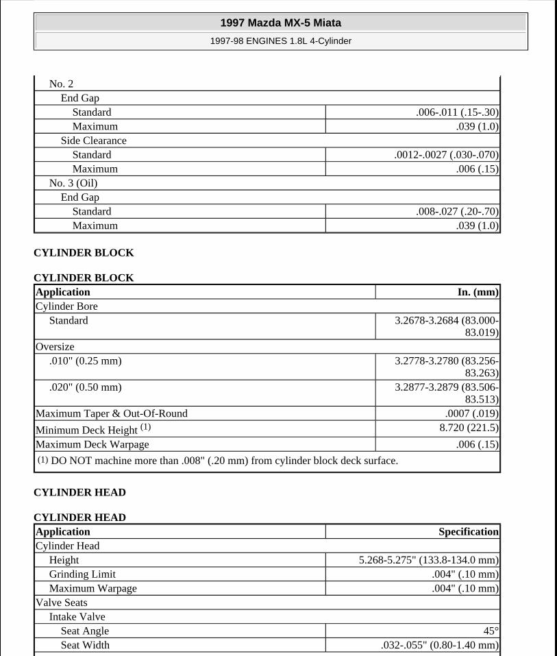
No. 2End Gap
Standard .006-.011 (.15-.30)Maximum .039 (1.0)
Side ClearanceStandard .0012-.0027 (.030-.070)Maximum .006 (.15)
No. 3 (Oil)End Gap
Standard .008-.027 (.20-.70)Maximum .039 (1.0)
Application In. (mm)Cylinder Bore
Standard 3.2678-3.2684 (83.000-83.019)
Oversize.010" (0.25 mm) 3.2778-3.2780 (83.256-
83.263).020" (0.50 mm) 3.2877-3.2879 (83.506-
83.513)Maximum Taper & Out-Of-Round .0007 (.019)
Minimum Deck Height (1) 8.720 (221.5)
Maximum Deck Warpage .006 (.15)(1) DO NOT machine more than .008" (.20 mm) from cylinder block deck surface.
Application SpecificationCylinder Head
Height 5.268-5.275" (133.8-134.0 mm)Grinding Limit .004" (.10 mm)Maximum Warpage .004" (.10 mm)
Valve SeatsIntake Valve
Seat Angle 45°Seat Width .032-.055" (0.80-1.40 mm)
1997 Mazda MX-5 Miata
1997-98 ENGINES 1.8L 4-Cylinder
Microsoft
Sunday, July 05, 2009 1:55:15 PM Page 39 © 2005 Mitchell Repair Information Company, LLC.

VALVES & VALVE SPRINGS
VALVES & VALVE SPRINGS
Exhaust ValveSeat Angle 45°Seat Width .032-.055" (0.80-1.40 mm)
Valve GuidesIntake Valve
Valve Guide I.D. .2367-.2374" (6.01-6.03 mm)Valve Guide Installed
Height .721-.744" (18.3-18.9 mm)Valve Stem-To-Guide Oil Clearance
Standard .0010-.0023" (.025-.060 mm)Maximum .008" (.20 mm)
Exhaust ValveValve Guide I.D. .2367-.2374" (6.01-6.03 mm)Valve Guide Installed
Height .721-.744" (18.3-18.9 mm)Valve Stem-To-Guide Oil Clearance
Standard .0012-.0025" (.030-.065 mm)Maximum .008" (.20 mm)
Application SpecificationValves
Face Angle 45°Installed Height
Normal 1.772-1.791" (45.00-45.50 mm)Serviceable 1.733-1.772" (45.60-46.50 mm)
Minimum MarginIntake .035" (0.9 mm)Exhaust .039" (1.0 mm)
Refinish LengthMiata
IntakeStandard 4.0114" (101.89 mm)Minimum 3.9524" (100.39 mm)
ExhaustStandard 4.0153" (101.99 mm)Minimum 3.9563" (100.49 mm)
ProtegeIntake
1997 Mazda MX-5 Miata
1997-98 ENGINES 1.8L 4-Cylinder
Microsoft
Sunday, July 05, 2009 1:55:15 PM Page 40 © 2005 Mitchell Repair Information Company, LLC.

CAMSHAFT
CAMSHAFT
Standard 3.9741-4.0055" (100.94-101.74 mm)
Minimum 3.9701" (100.84 mm)Exhaust
Standard 3.9780-4.0094" (101.04-101.84 mm)
Minimum 3.9661" (100.74 mm)Stem Diameter
IntakeStandard .2351-.2356" (5.970-5.985 mm)Minimum .2331" (5.920 mm)
ExhaustStandard .2349-.2354" (5.965-5.980 mm)Minimum .2329" (5.915 mm)
Valve SpringsFree Length 1.821" (46.26 mm)Maximum Out-Of-Square .064" (1.62 mm)
Lbs. @ In. (kg @ mm)Compressed Length
Minimum 51-55 @ 1.555 (23-25 @ 39.50)
Application In. (mm)End Play
Standard .0028-.0074 (.07-.19)Maximum .008 (.20)
Journal Diameter 1.0213-1.0222 (25.940-25.965)Maximum Journal Out-Of-Round .0012 (.03)Maximum Journal Runout .0012 (.03)Journal Oil Clearance
Standard .0014-.0031 (.035-.081)Maximum .006 (.15)
Lobe HeightStandard
Intake 1.7360 (44.094)Exhaust 1.7559 (44.600)
Minimum
1997 Mazda MX-5 Miata
1997-98 ENGINES 1.8L 4-Cylinder
Microsoft
Sunday, July 05, 2009 1:55:15 PM Page 41 © 2005 Mitchell Repair Information Company, LLC.

VALVE LIFTERS
VALVE LIFTERS
Intake 1.7281 (43.894)Exhaust 1.7480 (44.400)
Application In. (mm)Bore Diameter 1.1811-1.1821 (30.000-30.025)Lifter Diameter 1.1795-1.1802 (29.959-29.975)Oil Clearance
Standard .0010-.0026 (.025-.066)Maximum .0071 (.180)
1997 Mazda MX-5 Miata
1997-98 ENGINES 1.8L 4-Cylinder
Microsoft
Sunday, July 05, 2009 1:55:15 PM Page 42 © 2005 Mitchell Repair Information Company, LLC.