primary aberration contribution to incoherent backscatter heterodyne lidar returns
TRANSCRIPT
Primary aberration contribution to incoherent backscatterheterodyne lidar returns
B. J. Rye
The optics of a coherent lidar system using incoherent backscatter is modeled in a way that allows restiltsof the wave theory of aberrations to be applied directly. Parametric plots are obtained showing the aberra-tion and range dependence of the effective antenna area using truncated Gaussian beams. The Rayleighcriterion is an adequate guide to the optical tolerances required for the far-field return, and in the near fieldreturns are not necessarily degraded by aberrations. Examples are given for the range weighting of returnsfor various primary mirror configurations.
1. Introduction
As a coherent receiver is sensitive to distortion of thesignal phase fronts arising between the source and thephotodetector, an optical system of reasonably highquality is demanded. Since the phase depends on theoptical path length normalized to the wavelength X, thisrequirement becomes increasingly severe as A is reducedand for radar will be more significant in the optical thanin the microwave spectrum. Losses due to aberrationshave been computed' for communications systems usingoptical heterodyning of coherent signals. In this paperan approach based directly on the diffraction theory ofaberrations is developed and applied in the context ofincoherent backscatter heterodyne lidar. Phase frontfluctuations arising from atmospheric refractive tur-bulence are neglected throughout.
II. Incoherent Backscatter Lidar
A. Fourier Optics Approach to Coherent Reception
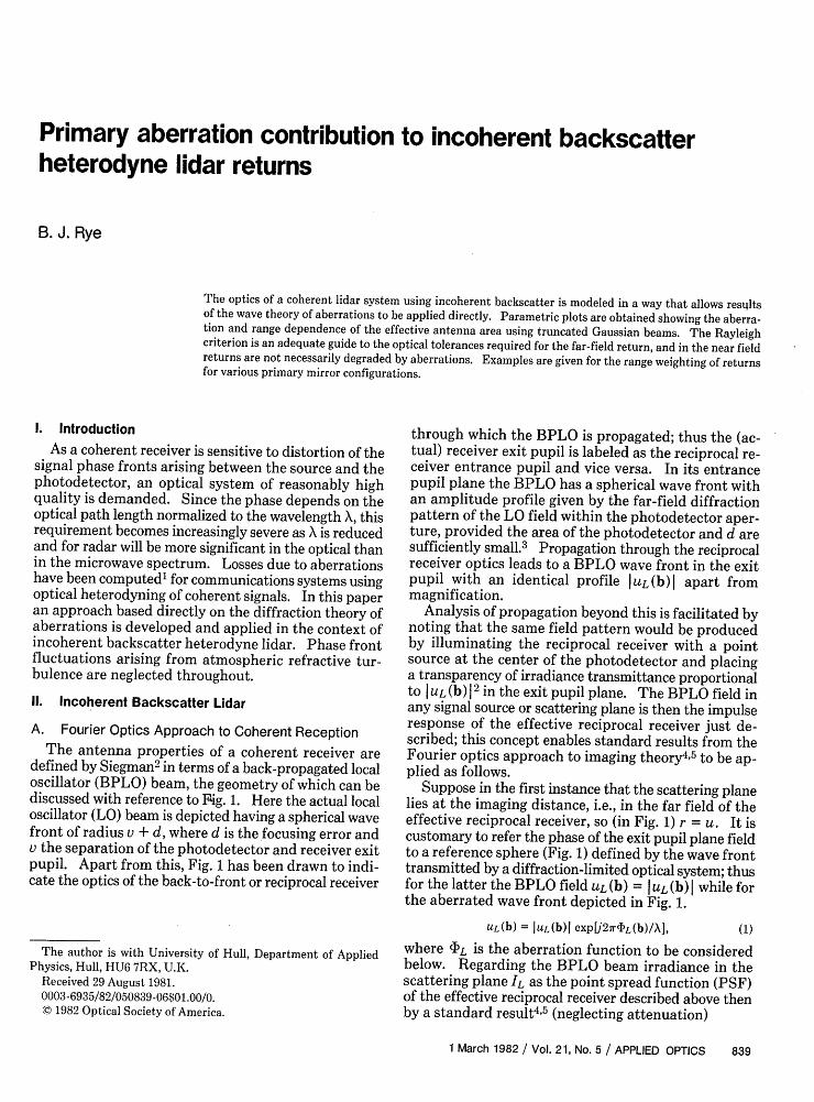
The antenna properties of a coherent receiver aredefined by Siegman2 in terms of a back-propagated localoscillator (BPLO) beam, the geometry of which can bediscussed with reference to Fig. 1. Here the actual localoscillator (LO) beam is depicted having a spherical wavefront of radius v + d, where d is the focusing error andv the separation of the photodetector and receiver exitpupil. Apart from this, Fig. 1 has been drawn to indi-cate the optics of the back-to-front or reciprocal receiver
through which the BPLO is propagated; thus the (ac-tual) receiver exit pupil is labeled as the reciprocal re-ceiver entrance pupil and vice versa. In its entrancepupil plane the BPLO has a spherical wave front withan amplitude profile given by the far-field diffractionpattern of the LO field within the photodetector aper-ture, provided the area of the photodetector and d aresufficiently small.3 Propagation through the reciprocalreceiver optics leads to a BPLO wave front in the exitpupil with an identical profile UL (b) I apart frommagnification.
Analysis of propagation beyond this is facilitated bynoting that the same field pattern would be producedby illuminating the reciprocal receiver with a pointsource at the center of the photodetector and placinga transparency of irradiance transmittance proportionalto IUL (b) 12 in the exit pupil plane. The BPLO field inany signal source or scattering plane is then the impulseresponse of the effective reciprocal receiver just de-scribed; this concept enables standard results from theFourier optics approach to imaging theory4 5 to be ap-plied as follows.
Suppose in the first instance that the scattering planelies at the imaging distance, i.e., in the far field of theeffective reciprocal receiver, so (in Fig. 1) r = u. It iscustomary to refer the phase of the exit pupil plane fieldto a reference sphere (Fig. 1) defined by the wave fronttransmitted by a diffraction-limited optical system; thusfor the latter the BPLO field UL (b) = I UL (b) I while forthe aberrated wave front depicted in Fig. 1.
UL(b) = IUL(b)l expU27r1L(b)/X],
The author is with University of Hull, Department of AppliedPhysics, Hull, HU6 7RX, U.K.
Received 29 August 1981.0003-6935/82/050839-06$01.00/0.(© 1982 Optical Society of America.
where 'L is the aberration function to be consideredbelow. Regarding the BPLO beam irradiance in thescattering plane IL as the point spread function (PSF)of the effective reciprocal receiver described above thenby a standard result4 5 (neglecting attenuation)
1 March 1982 / Vol. 21, No. 5 / APPLIED OPTICS 839
(1)
Reciprocal
j . r - 5 OilR-0 - r -: I Phseront 8 I\
: : Reference / ApertureI @ sphere / area AR
d
a
L 0. beamphasetront
Fig. 1. Reciprocal receiver geometry.
B. Effective Transmitter
The optics of the transmitted beam can be describedin an analogous manner. In particular, the scatteringplane irradiance IT(S) can be regarded as the PSF of aneffective transmitter so
IT(S) = TTPoF[sAT(f)I
where the effective transmitter OTF is
AT(f) = S/2(f ')UT(f + f')d 2f'.TTPO
(5)
(6)
Here P0 is the laser source power, TT the transmittertransmission factor, and (within the exit pupil aper-ture)
UT(b) = IUT(b)l expLUzr'1T(b)/X].
- Targetplane
(7)
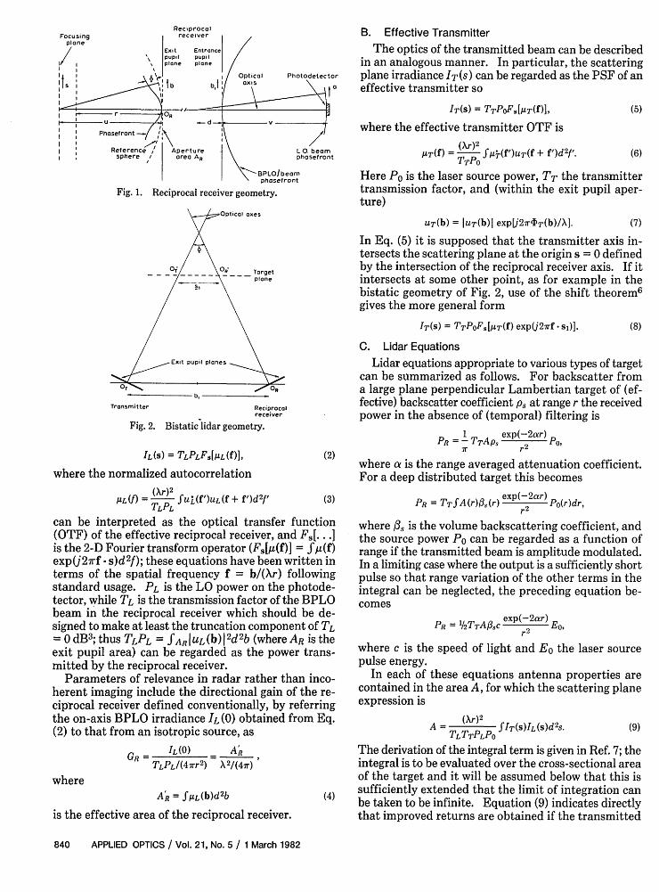
In Eq. (5) it is supposed that the transmitter axis in-tersects the scattering plane at the origin s = 0 definedby the intersection of the reciprocal receiver axis. If itintersects at some other point, as for example in thebistatic geometry of Fig. 2, use of the shift theorem6
gives the more general form
IT(S) = TTPOFs.[AT(f) exp(j27rf s1 )]. (8)
Transmitter Reciprocalreceiver
Fig. 2. Bistaticlidar geometry.
IL(S) = TLPLFjAL(f)1,
where the normalized autocorrelation
AL(f) = (r) fUL(f')UL(f+ f')d 2f'TLPL
(2)
(3)
can be interpreted as the optical transfer function(OTF) of the effective reciprocal receiver, and F,[...]is the 2-D Fourier transform operator (F,[4(f)] = Sz(f)exp(j27rf s)d2f); these equations have been written interms of the spatial frequency f = b/(Xr) followingstandard usage. PL is the LO power on the photode-tector, while TL is the transmission factor of the BPLObeam in the reciprocal receiver which should be de-signed to make at least the truncation component of TL- 0 dB3 ; thus TLPL = SAR I UL (b) I 2d 2b (where AR is theexit pupil area) can be regarded as the power trans-mitted by the reciprocal receiver.
Parameters of relevance in radar rather than inco-herent imaging include the directional gain of the re-ciprocal receiver defined conventionally, by referringthe on-axis BPLO irradiance IL (0) obtained from Eq.(2) to that from an isotropic source, as
GR= IL(O) ARTLPLI(47rr2) X2/(47r)
whereAR = f/IL(b)d 2 b
is the effective area of the reciprocal receiver.
C. Lidar Equations
Lidar equations appropriate to various types of targetcan be summarized as follows. For backscatter froma large plane perpendicular Lambertian target of (ef-fective) backscatter coefficient Ps at range r the receivedpower in the absence of (temporal) filtering is
1 exp(-2ar)PR =-TTAPS PO,
7r r2
where a is the range averaged attenuation coefficient.For a deep distributed target this becomes
PR = TTfA(r)13(r) e 2 Po(r)dr,
where /3, is the volume backscattering coefficient, andthe source power Po can be regarded as a function ofrange if the transmitted beam is amplitude modulated.In a limiting case where the output is a sufficiently shortpulse so that range variation of the other terms in theintegral can be neglected, the preceding equation be-comes
P,, = %T A exp(-2ar) E
where c is the speed of light and E0 the laser sourcepulse energy.
In each of these equations antenna properties arecontained in the area A, for which the scattering planeexpression is
A = TTr ITWIL(sdS.TLTTPLPO
(9)
The derivation of the integral term is given in Ref. 7; theintegral is to be evaluated over the cross-sectional areaof the target and it will be assumed below that this is
(4 sufficiently extended that the limit of integration can(4) be taken to be infinite. Equation (9) indicates directly
that improved returns are obtained if the transmitted
840 APPLIED OPTICS / Vol. 21, No. 5 / 1 March 1982
Focusingplane
i l
I
and BPLO beam profiles are spatially concentrated;factors tending to diverge or reduce the overlap of thesebeams degrade the signal.
In conjunction with Eqs. (2) and (8) the power theo-rem6 shows that Eq. (9) is equivalent to the antennaplane expression
A = (r) 2 fuT(f)Ai(f) exp(27rf sl)d 2f (10)
or, for an aligned coaxial system with s = 0 at allranges,
A = fAT(b)AL(b)d 2 b. (11)
The last form was used previously,3 specifically in thediffraction-limited approximation with circular sym-metry. It is shown there that the effective transmitterarea defined by analogy with Eq. (4) as
AT = fAT(b)d 2b (12)
equals what can be regarded for the purpose of thesecalculations as the area of a return field speckle element.From Eq. (11) it follows that when AR is sufficientlylarge compared with AT[i4(b) 1 over the spatial ex-tent of AuT(b)] the lidar area A is restricted to a maxi-mum value equal to this speckle element area. Theperformance of the antenna system in the far field canthen be characterized by the parameter
TTA
= ATwhere AT is the area of the transmitter exit pupil. 7ahas the maximum value unity (0 dB) in the limiting caseof uniform I UL (b) I and diffraction-limited optics (so A+= AT), if AR >> AT (so A = AT as above) and TT = 1.In the following sections this is examined quantitativelyand extended to consider the contribution of aberra-tions parametrically in the far and near fields.
Ill. Parametric Plots of M7a
While the relations obtained so far are applicable toarbitrary field profiles UT,L (b), the transmitter profileconsidered in this section has the Gaussian form
IUT(b) = (2/7r)1/2 exp[-b 2 /(YTbT) 21, (13)YTbT
where bT is the diameter of the outer rim of a circulartransmitter and YTbT the irradiance l/e2 radius, fromwhich it follows that TT = 1 - exp(-2/y 2). There isassumed to be no central obscuration and s, = 0.
A. The Far-Field Diffraction-Limited Return
Here the BPLO profile is taken as either uniform orGaussian with
|UL(b) = (2/7r)l/2 exp[-b2 /('YLbR) 2]. (14)YLbR
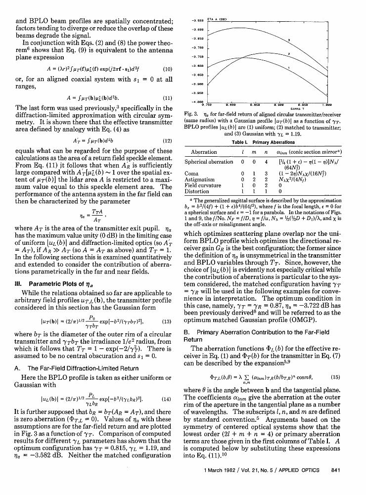
It is further supposed that bR = bT(AR = AT), and thereis zero aberration (T,L = 0). Values of 7 with theseassumptions are for the far-field return and are plottedin Fig. 3 as a function-of YT. Comparison of computedresults for different YL parameters has shown that theoptimum configuration has YT = 0.815, YL = 1.19, and77a = -3.582 dB. Neither the matched configuration
-3.650
-3. e0
-3.750 3
-3. 780
-3.850
-3.900
-3. 950
-4.0000.75 e 0,800 e.80 0.900 0.950 .000
GAMMA T
Fig. 3. 7 for far-field return of aligned circular transmitter/receiver(same radius) with a Gaussian profile uT(b)I as a function of YT.
BPLO profiles IuL(b)I are (1) uniform; (2) matched to transmitter;and (3) Gaussian with Y'L = 119.
Table 1. Primary Aberrations
Aberration I m n ainm (conic section mirror")
Spherical aberration 0 0 4 [1/4 (1 + E) - i(1 -,)N
(64NA)Coma 0 1 3 (1 - 271)Nxx/(16N')Astigmatism 0 2 2 NxX 2/(4Nf)Field curvature 1 0 2 0Distortion 1 1 1 0
a The generalized sagittal surface is described by the approximationb = b2 /(4f) + (1 + c)b4/(64f3 ), where f is the focal length, e = 0 fora spherical surface and e = -1 for a parabola. In the notations of Figs.1 and 9, the f/No. NF = f/D, 1 = f/u, N, = /2('/2D + D1 )/X, and X isthe off-axis or misalignment angle.
which optimizes scattering plane overlap nor the uni-form BPLO profile which optimizes the directional re-ceiver gain GR is the best configuration; the former sincethe definition of 71a is unsymmetrical in the transmitterand BPLO variables through TT. Since, however, thechoice of UL (b) I is evidently not especially critical whilethe contribution of aberrations is particular to the sys-tem considered, the matched configuration having YT= YR will be used in the following examples for conve-nience in interpretation. The optimum condition inthis case, namely, YT = YR = 0.87, 1a = -3.722 dB hasbeen previously derived8 and will be referred to as theoptimum matched Gaussian profile (OMGP).
B. Primary Aberration Contribution to the Far-FieldReturn
The aberration functions ?L (b) for the effective re-ceiver in Eq. (1) and cIT(b) for the transmitter in Eq. (7)can be described by the expansion5'9
(15)bT,L(b,O) = X A (anm)T,R(b/bTR)n cosmO,n,m
where 0 is the angle between b and the tangential plane.The coefficients alnm give the aberration at the outerrim of the aperture in the tangential plane as a numberof wavelengths. The subscripts 1, n, and m are definedby standard convention.5 Arguments based on thesymmetry of centered optical systems show that thelowest order (21 + m + n = 4) or primary aberrationterms are those given in the first columns of Table I. Ais computed below by substituting these expressionsinto Eq. (11).10
1 March 1982 / Vol. 21, No. 5 / APPLIED OPTICS 841
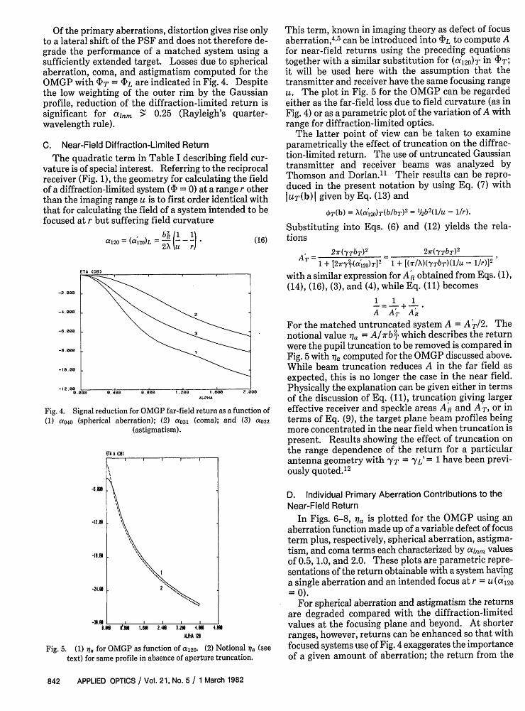
Of the primary aberrations, distortion gives rise onlyto a lateral shift of the PSF and does not therefore de-grade the performance of a matched system using asufficiently extended target. Losses due to sphericalaberration, coma, and astigmatism computed for theOMGP with IT = (DL are indicated in Fig. 4. Despitethe low weighting of the outer rim by the Gaussianprofile, reduction of the diffraction-limited return issignificant for lnm >: 0.25 (Rayleigh's quarter-wavelength rule).
C. Near-Field Diffraction-Limited Return
The quadratic term in Table I describing field cur-vature is of special interest. Referring to the reciprocalreceiver (Fig. 1), the geometry for calculating the fieldof a diffraction-limited system (4 = 0) at a range r otherthan the imaging range u is to first order identical withthat for calculating the field of a system intended to befocused at r but suffering field curvature
120 = (a120)L b,1 1 ~clOL2X u ri
-2.000
-4.500
-e . 000
-8.000
- 00
-12.00 .0.000 0.400 0.80
Fig. 4. Signal reduction for OMGP far(1) CeO40 (spherical aberration); (2)
(astigmatism
ETA A ()
8eN
-I8.
-24. 1
-3e. LUeS
(16)
This term, known in imaging theory as defect of focusaberration,4 5 can be introduced into (?L to compute Afor near-field returns using the preceding equationstogether with a similar substitution for (a120)T in (PT;it will be used here with the assumption that thetransmitter and receiver have the same focusing rangeU. The plot in Fig. 5 for the OMGP can be regardedeither as the far-field loss due to field curvature (as inFig. 4) or as a parametric plot of the variation of A withrange for diffraction-limited optics.
The latter point of view can be taken to examineparametrically the effect of truncation on the diffrac-tion-limited return. The use of untruncated Gaussiantransmitter and receiver beams was analyzed byThomson and Dorian."' Their results can be repro-duced in the present notation by using Eq. (7) withlUT(b) given by Eq. (13) and
OT(b) = X(a'120)T(b/bT)2 = 1/2 b2 (1/u - 1/r).
Substituting into Eqs. (6) and (12) yields the rela-tions
21r(YTbT)2 21r(YTbT)2
1 + [27ryT(a2o)TV 1 + [(r/X)(YTbT)(1/u- 1/r)12
with a similar expression for AR obtained from Eqs. (1),(14), (16), (3), and (4), while Eq. (11) becomes
1 1 1_= + _ .A AT AR
For the matched untruncated system A = A +/2. Thenotional value 1 = A/7rb2 which describes the returnwere the pupil truncation to be removed is compared inFig. 5 with aa computed for the OMGP discussed above.While beam truncation reduces A in the far field asexpected, this is no longer the case in the near field.
, 200 , 60a 2.5 00 Physically the explanation can be given either in termsALPHA of the discussion of Eq. (11), truncation giving larger
'-field return as a function of effective receiver and speckle areas AR and AT, or ina031 (coma); and (3) aO22 terms of Eq. (9), the target plane beam profiles being
more concentrated in the near field when truncation ispresent. Results showing the effect of truncation onthe range dependence of the return for a particularantenna geometry with YT = YLE = 1 have been previ-ously quoted.' 2
T.* I 141 2.4 32 441
MA 129
Fig. 5. (1) jt for OMGP as function of a12o. (2) Notional 7a (seetext) for same profile in absence of aperture truncation.
D. Individual Primary Aberration Contributions to theNear-Field Return
In Figs. 6-8, 1a is plotted for the OMGP using anaberration function made up of a variable defect of focusterm plus, respectively, spherical aberration, astigma-tism, and coma terms each characterized by cxlnm valuesof 0.5, 1.0, and 2.0. These plots are parametric repre-sentations of the return obtainable with a system havinga single aberration and an intended focus at r = u(a'120=0).
For spherical aberration and astigmatism the returnsare degraded compared with the diffraction-limitedvalues at the focusing plane and beyond. At shorterranges, however, returns can be enhanced so that withfocused systems use of Fig. 4 exaggerates the importanceof a given amount of aberration; the return from the
842 APPLIED OPTICS / Vol. 21, No. 5 / 1 March 1982
2K
III
I I I I 0
-4. 000
-12.05
-10.00
-20.00
-24.00 -
-20.500-4.800 -3.200 - .00 -0 000 1 .000 3.200 4.800
ALPHA 120
Fig. 6. 77a for OMGP in the presence of spherical aberration and fieldcurvature as a function of a 1 2O (1) aO4O= 0 (2) aO40 = 0-5; (3) ao4O
1; and (4) aO 4 O 2.
ETA A DO)
-0.005
-24.00
-28. 00L-4.800 -3.200 -I .600 -0 .000 .S60 3.200 4.800
ALPHA 120
Fig. 7. As Fig. 6 but in the presence of astigmatism and field cur-vature: (1) a022 = 0, (2) a022 = 0.5; (3) a22 = 1; and (4) a022 = 2.
ETA A (O)
.. ,-48 3
-8998;
-20.99
-28.999.1
AA 12
Fig. 8. As Fig. 6 but in the presence of coma and field curvature: (1)(YO31 = 0; (2) a0 31 = 0.5; (3) a031 = 1; and (4) a031 = 2.
intended focusing plane can be improved by refocusingthe system at longer range. Spherical aberration leadsto a maximum return (Fig. 6) in the vicinity of the planeof the circle of least confusion which is understandablein terms of Eq. (9) since this is where the target planebeam irradiance is most concentrated. The broadening
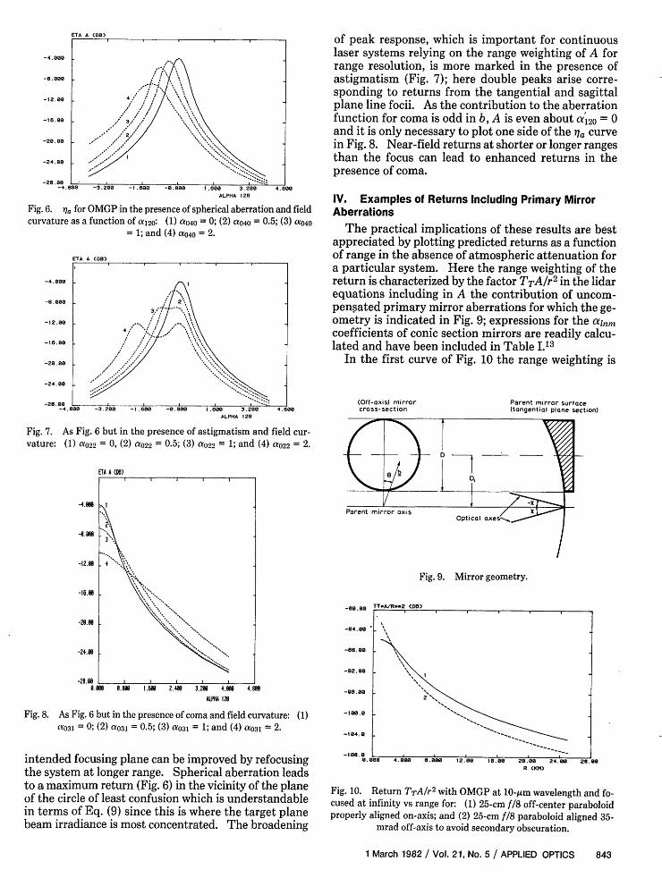
of peak response, which is important for continuouslaser systems relying on the range weighting of A forrange resolution, is more marked in the presence ofastigmatism (Fig. 7); here double peaks arise corre-sponding to returns from the tangential and sagittalplane line focii. As the contribution to the aberrationfunction for coma is odd in b, A is even about a120 = 0and it is only necessary to plot one side of the 7a curvein Fig. 8. Near-field returns at shorter or longer rangesthan the focus can lead to enhanced returns in thepresence of coma.
IV. Examples of Returns Including Primary MirrorAberrations
The practical implications of these results are bestappreciated by plotting predicted returns as a functionof range in the absence of atmospheric attenuation fora particular system. Here the range weighting of thereturn is characterized by the factor TTA/r2 in the lidarequations including in A the contribution of uncom-pensated primary mirror aberrations for which the ge-ometry is indicated in Fig. 9; expressions for the alnmcoefficients of conic section mirrors are readily calcu-lated and have been included in Table I.13
In the first curve of Fig. 10 the range weighting is
(Off-axis) mirrorcross-section
Parent mirror surface(tangential plane section)
Fig. 9. Mirror geometry.
R CK")
Fig. 10. Return TTA/r 2 with OMGP at 10-Am wavelength and fo-cused at infinity vs range for: (1) 25-cm f/8 off-center paraboloidproperly aligned on-axis; and (2) 25-cm f/8 paraboloid aligned 35-
mrad off-axis to avoid secondary obscuration.
1 March 1982 / Vol. 21, No. 5 / APPLIED OPTICS 843
R (KM)
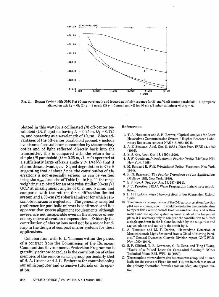
Fig. 11. Return TTA/r 2 with OMGP at 10-pm wavelength and focused at infinity vs range for 30-cm f/l off-center paraboloid: (1) properlyaligned on axis (X = 0); (2) x = 2 mrad; (3) x = 5 mrad; and (4) for 30-cm f/2 spherical mirror with X = 0.
plotted in this way for a collimated f/8 off-center pa-raboloid (OCP) system having D = 0.25 m, D1 = 0.175m, and operating at a wavelength of 10 gim. Since ad-vantages of the off-center paraboloid geometry includeavoidance of central beam obscuration by the secondaryoptics and of light reflected directly back into thetransmitter, this is compared with the return for asimple f/8 paraboloid (D = 0.25 m, DI = 0) operated ata sufficiently large off-axis angle X > 1/(4Nf) that itshares these advantages. Signal degradation is <2 dBsuggesting that at these f nos. the contribution of ab-errations is not especially serious (as can be verifiedusing the alnm formulas of Table I). In Fig. 11 the rangeweighting is plotted for an otherwise similar 30-cm f/1OCP at misalignment angles of 0, 2, and 5 mrad andcompared with the returns for a diffraction-limitedsystem and a 30-cm f/2 spherical mirror for which cen-tral obscuration is neglected. The generally acceptedpreference for parabolic mirrors is confirmed, and it isapparent that system alignment requirements, althoughsevere, are not insuperable even in the absence of sec-ondary mirror aberration compensation. Evidently thecontribution of aberrations need not be a major hand-icap in the design of compact mirror systems for theseapplications.
Collaboration with E. L. Thomas within the periodof a contract from the Commission of the EuropeanCommunities Environments Protection Programme isgratefully acknowledged, as is the contribution of othermembers of the remote sensing group particularly thatof B. A. Greene and J. C. Petheram for commissioningour minicomputer and extensive tutorials on its oper-ation.
References
1. T. A. Nussmeier and S. H. Brewer, "Optical Analysis for LaserHeterodyne Communication System," Hughes Research Labo-ratory Report on contract NAS 5-21898 (1974).
2. A. E. Siegman, Appl. Opt. 5, 1588 (1966); Proc. IEEE 54, 1350(1966).
3. B. J. Rye, Appl. Opt. 18, 1390 (1979).4. J. W. Goodman, Introduction to Fourier Optics (McGraw-Hill,
New York, 1968).5. M. Born and E. Wolf, Principles of Optics (Pergamon, New York,
1964).6. R. N. Bracewell, The Fourier Transform and its Applications
(McGraw-Hill, New York, 1979).7. B. J. Rye, J. Opt. Soc. Am. 71, 687 (1981).8. J. T. Priestley, NOAA Wave Propagation Laboratory; unpub-
lished.9. H. H. Hopkins, Wave Theory of Aberrations (Clarendon, Oxford,
1950).10. The numerical computation of the 2-D autocorrelation function
p(b) was, of course, slow. It would be useful for anyone intendingto repeat this exercise to note that because the integrand is Her-mitian and the optical system symmetric about the tangentialplane, it is necessary only to compute the contribution to A froma single quadrant in the b plane bounded by the tangential andsagittal planes and multiply the result by 4.
11. A. Thomson and M. F. Dorian, "Heterodyne Detection ofMonochromatic Light Scattered from a Cloud of Moving Parti-cles," General Dynamics Convair Division report GNC-ERR-Nov-1090 (1967).
12. S. F. Clifford, T. R. Lawrence, G. R. Ochs, and Ting-i Wang,"Study of a Pulsed Laser for Cross-wind Sensing," NOAATechnical Memo ERL WPL-48 (1980).
13. The complete mirror aberration function was computed numer-ically for the curves of Figs. (10) and (11), but in each case use ofthe primary aberration formulas was an adequate approxima-tion.
844 APPLIED OPTICS / Vol. 21, No. 5 / 1 March 1982