presented by agilent technologies - keysight.com · coverage area of an e-nodeb. 7.3 reference...
TRANSCRIPT
© 2013 Agilent Technologies
Wireless Communications
Your LTE Devices Need to
Pass Conformance Tests – Now
What? Presented by
Agilent Technologies

© 2013 Agilent Technologies
Wireless Communications
2 © 2013 Agilent Technologies
Wireless Communications
Agenda
2
Conformance Test Introduction
LTE Conformance and Certification
Operator Acceptance Testing
Challenges of LTE UE Testing
© 2013 Agilent Technologies
Wireless Communications
3 © 2013 Agilent Technologies
Wireless Communications
Agenda
3
Conformance Test Introduction
LTE Conformance and Certification
Operator Acceptance Testing
Challenges of LTE UE Testing
© 2013 Agilent Technologies
Wireless Communications
4 © 2013 Agilent Technologies
Wireless Communications
What is “Conformance Test”?
4
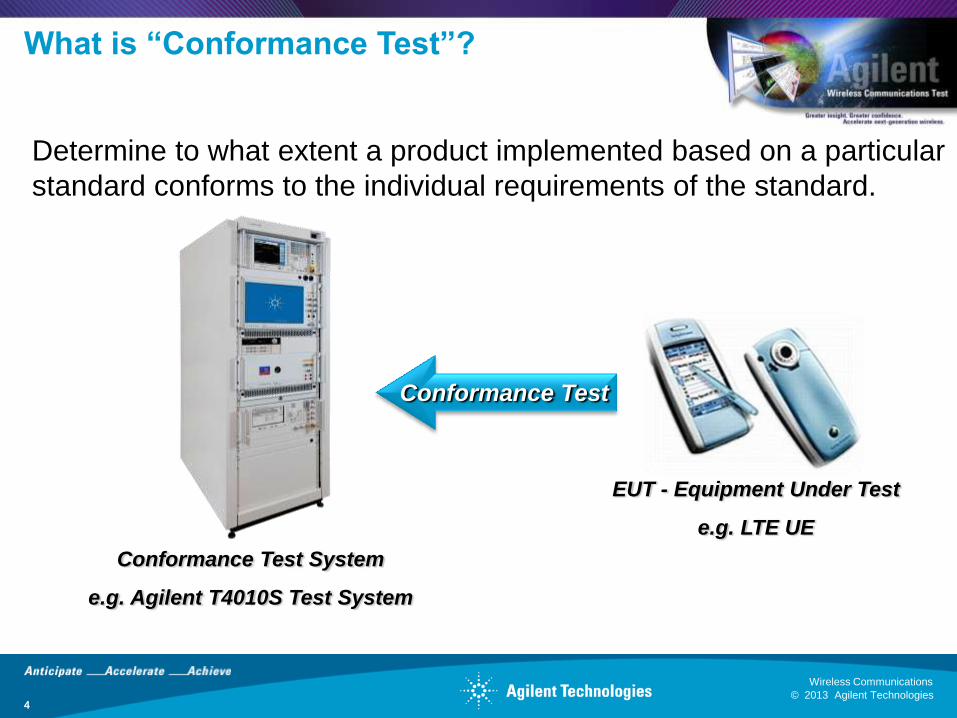
Determine to what extent a product implemented based on a particular
standard conforms to the individual requirements of the standard.
Conformance Test System
e.g. Agilent T4010S Test System
EUT - Equipment Under Test
e.g. LTE UE
Conformance Test

© 2013 Agilent Technologies
Wireless Communications
5 © 2013 Agilent Technologies
Wireless Communications
Defining Conformance
5
Specific set of tests performed:
• According to standards, i.e. Test Specifications
• By an accredited test lab (could be lab owned by manufacturer)
• On a ‘recognized’ test platform
Test Specs
- A set of test cases
- Includes bands of operation
- Constantly evolves, over
‘releases’
Test Platform
Validation
- Approved test systems/tools
/instruments
- RF, Protocol or RRM
- Must keep pace with standards
- Proof validation for a certain
percentage (e.g. 80%) to be approved
Lab
Accreditation
- Lab must fulfill a set of
requirements defined by a 3rd
party, e.g. ISO 17025.
- Must use validated TPs.
- Might involve auditing
process.
© 2013 Agilent Technologies
Wireless Communications
6 © 2013 Agilent Technologies
Wireless Communications
When to Perform “Conformance Test”?
6
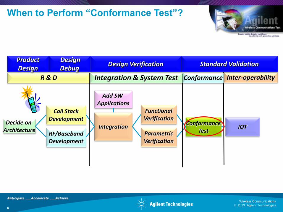
Decide on Architecture
RF/Baseband Development
Call Stack Development
Integration
Functional Verification
Parametric Verification
Add SW Applications
Conformance Test
IOT
R & D Integration & System Test Conformance Inter-operability
Design Verification Product Design
Design Debug
Standard Validation
© 2013 Agilent Technologies
Wireless Communications
7 © 2013 Agilent Technologies
Wireless Communications
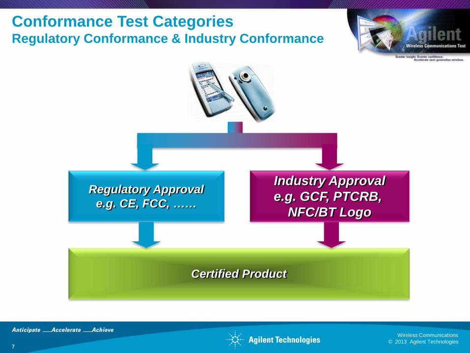
Conformance Test Categories Regulatory Conformance & Industry Conformance
7
Industry Approval
e.g. GCF, PTCRB,
NFC/BT Logo
Regulatory Approval
e.g. CE, FCC, ……
Certified Product
© 2013 Agilent Technologies
Wireless Communications
8 © 2013 Agilent Technologies
Wireless Communications
Agenda
8
Conformance Test Introduction
LTE Conformance and Certification
Operator Acceptance Testing
Challenges of LTE UE Testing
© 2013 Agilent Technologies
Wireless Communications
9 © 2013 Agilent Technologies
Wireless Communications
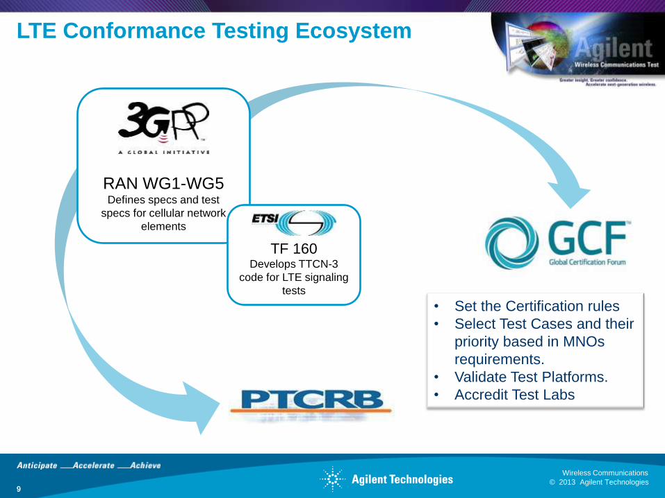
RAN WG1-WG5 Defines specs and test
specs for cellular network
elements
9
LTE Conformance Testing Ecosystem
TF 160 Develops TTCN-3
code for LTE signaling
tests
• Set the Certification rules
• Select Test Cases and their
priority based in MNOs
requirements.
• Validate Test Platforms.
• Accredit Test Labs
© 2013 Agilent Technologies
Wireless Communications
10 © 2013 Agilent Technologies
Wireless Communications
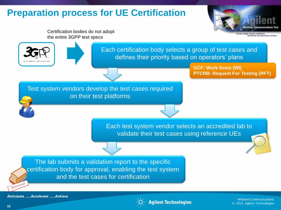
Preparation process for UE Certification
10
Each certification body selects a group of test cases and
defines their priority based on operators’ plans
Test system vendors develop the test cases required
on their test platforms
Each test system vendor selects an accredited lab to
validate their test cases using reference UEs
The lab submits a validation report to the specific
certification body for approval, enabling the test system
and the test cases for certification
Certification bodies do not adopt
the entire 3GPP test specs
GCF: Work Items (WI)
PTCRB: Request For Testing (RFT)
© 2013 Agilent Technologies
Wireless Communications
11 © 2013 Agilent Technologies
Wireless Communications
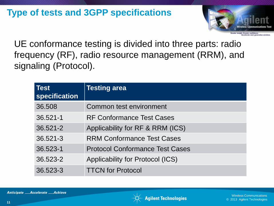
Type of tests and 3GPP specifications
11
Test
specification
Testing area
36.508 Common test environment
36.521-1 RF Conformance Test Cases
36.521-2 Applicability for RF & RRM (ICS)
36.521-3 RRM Conformance Test Cases
36.523-1 Protocol Conformance Test Cases
36.523-2 Applicability for Protocol (ICS)
36.523-3 TTCN for Protocol
UE conformance testing is divided into three parts: radio
frequency (RF), radio resource management (RRM), and
signaling (Protocol).
© 2013 Agilent Technologies
Wireless Communications
12 © 2013 Agilent Technologies
Wireless Communications
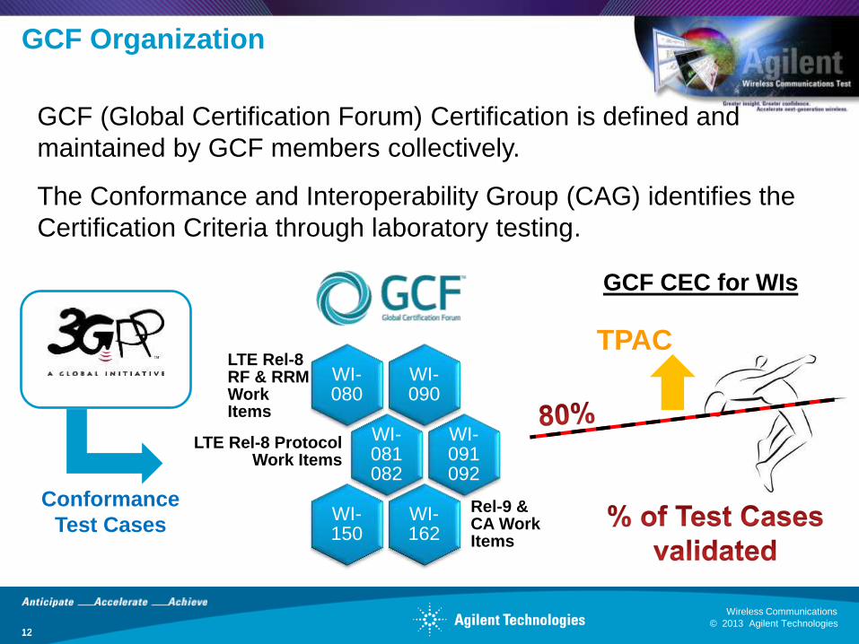
GCF Organization
12
GCF (Global Certification Forum) Certification is defined and
maintained by GCF members collectively.
The Conformance and Interoperability Group (CAG) identifies the
Certification Criteria through laboratory testing.
WI-090
LTE Rel-8 RF & RRM Work Items
WI-080
WI-081082
LTE Rel-8 Protocol Work Items
WI-091 092
WI-162
Rel-9 & CA Work Items
WI-150
Conformance
Test Cases
GCF CEC for WIs
TPAC

© 2013 Agilent Technologies
Wireless Communications
13 © 2013 Agilent Technologies
Wireless Communications
GCF Certification database
13
Is a test case mandatory for Certification?
Has it been validated? In which TPs?
© 2013 Agilent Technologies
Wireless Communications
14 © 2013 Agilent Technologies
Wireless Communications
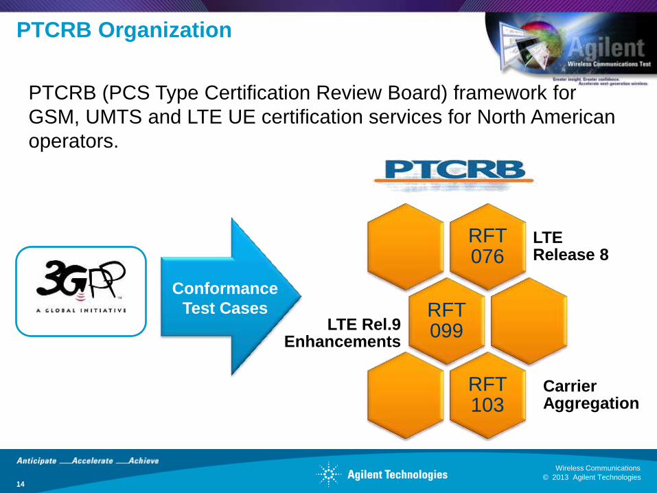
PTCRB Organization
14
PTCRB (PCS Type Certification Review Board) framework for
GSM, UMTS and LTE UE certification services for North American
operators.
RFT 076
LTE Release 8
RFT 099 LTE Rel.9
Enhancements
RFT 103
Carrier Aggregation
Conformance
Test Cases
© 2013 Agilent Technologies
Wireless Communications
15 © 2013 Agilent Technologies
Wireless Communications
Update in GCF/PTCRB 2013 activities
15
• Main work around LTE Rel-8
and Rel-9.
• In GCF, all bands activated for
Rel-8 except FDD 12 & 14.
• In Rel-9, validation started early
this year.
• New work items defined for CA
(WI-162/RFT 103).
• Validations expected by next
PVG#61 (May’13) and CAG#36
(Oct’13).
© 2013 Agilent Technologies
Wireless Communications
16 © 2013 Agilent Technologies
Wireless Communications
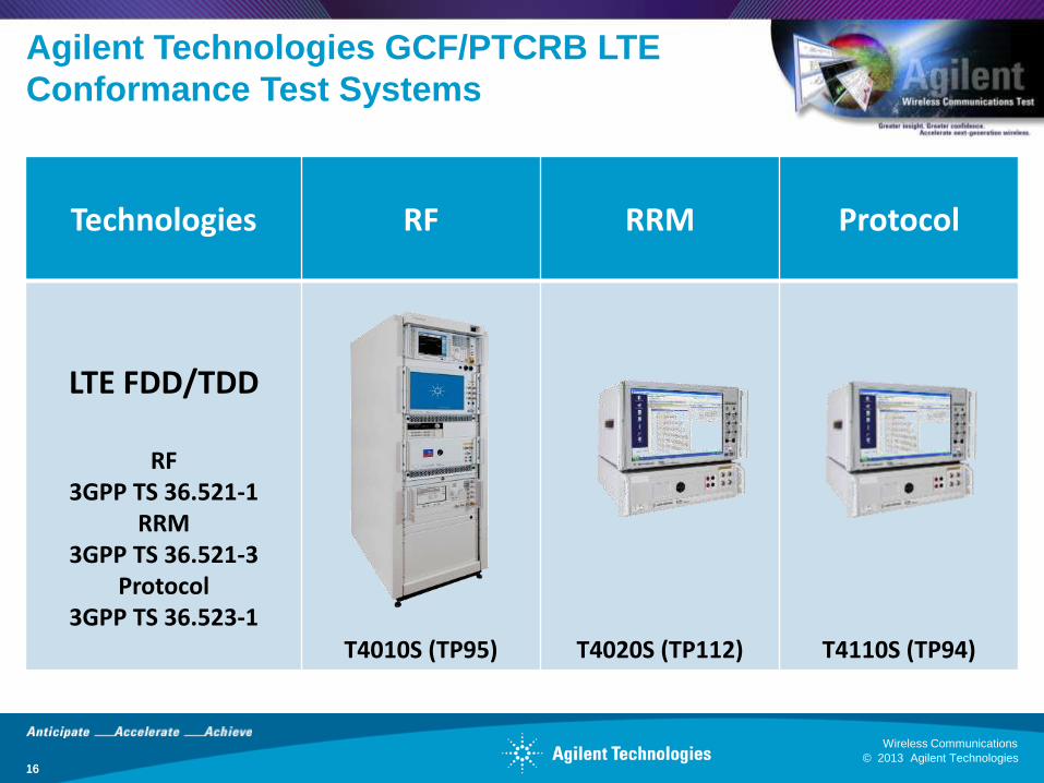
Agilent Technologies GCF/PTCRB LTE
Conformance Test Systems
16
Technologies RF RRM Protocol
LTE FDD/TDD
RF
3GPP TS 36.521-1 RRM
3GPP TS 36.521-3 Protocol
3GPP TS 36.523-1 T4010S (TP95) T4020S (TP112) T4110S (TP94)
© 2013 Agilent Technologies
Wireless Communications
17 © 2013 Agilent Technologies
Wireless Communications
Agenda
17
Conformance Test Introduction
LTE Conformance and Certification
Operator Acceptance Testing
Challenges of LTE UE Testing
© 2013 Agilent Technologies
Wireless Communications
18 © 2013 Agilent Technologies
Wireless Communications
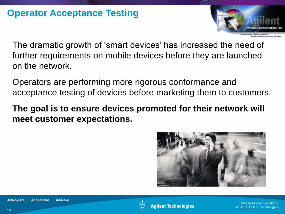
Operator Acceptance Testing
18
The dramatic growth of ‘smart devices’ has increased the need of
further requirements on mobile devices before they are launched
on the network.
Operators are performing more rigorous conformance and
acceptance testing of devices before marketing them to customers.
The goal is to ensure devices promoted for their network will
meet customer expectations.
© 2013 Agilent Technologies
Wireless Communications
19 © 2013 Agilent Technologies
Wireless Communications
Acceptance Tests
19
Designed around specific characteristics and conditions of the wireless network to
cover a multitude of scenarios that stress both network and UEs.
Details of an operator’s acceptance tests are usually confidential and differ in
specifications tested, measurement limits and implementation.
Operator’s technical requirements usually are:
• Regulatory: RF/EMC/Safety tests according to country standards
• Conformance: Tests against specific standards RF/protocol/SIM
• Interoperability: Tests compatibility between devices and devices to network.
• Functional Tests: Verification of functionalities and features.
• User Experience: Quality tests according to users expectations.
• Reliability: Endurance, extreme tests considering usage and different climatic
conditions.
© 2013 Agilent Technologies
Wireless Communications
20 © 2013 Agilent Technologies
Wireless Communications
Agenda
20
Conformance Test Introduction
LTE Conformance and Certification
Operator Acceptance Testing
Challenges of LTE UE Testing
© 2013 Agilent Technologies
Wireless Communications
21 © 2013 Agilent Technologies
Wireless Communications
Challenges of LTE UE Testing (I)
21
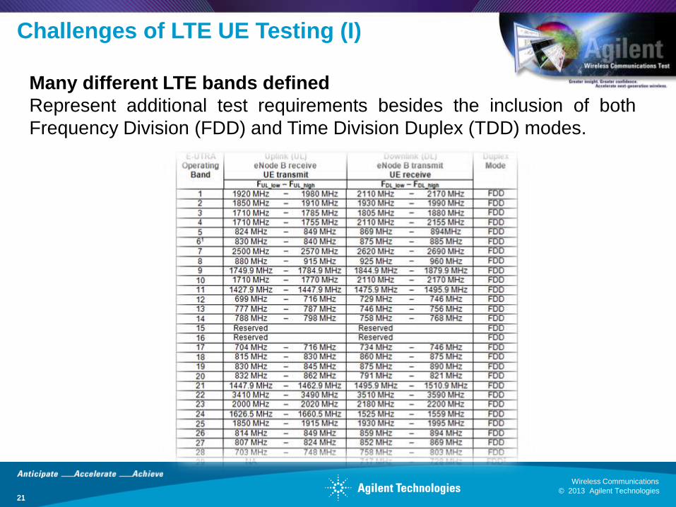
Many different LTE bands defined
Represent additional test requirements besides the inclusion of both
Frequency Division (FDD) and Time Division Duplex (TDD) modes.
© 2013 Agilent Technologies
Wireless Communications
22 © 2013 Agilent Technologies
Wireless Communications
Challenges of LTE UE Testing (II)
22
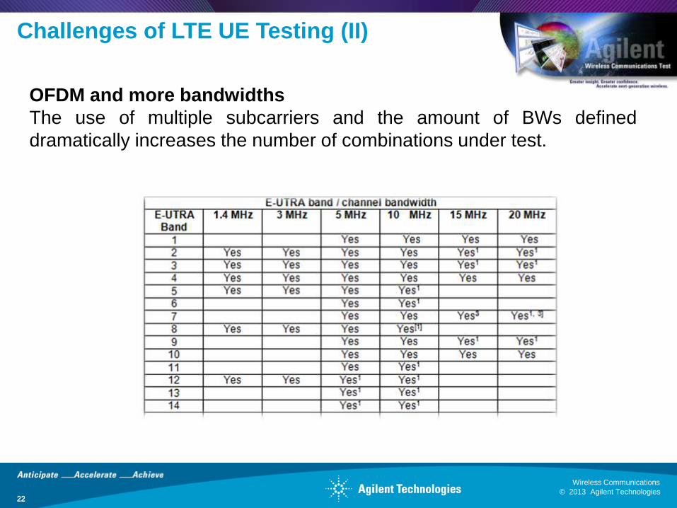
OFDM and more bandwidths
The use of multiple subcarriers and the amount of BWs defined
dramatically increases the number of combinations under test.
© 2013 Agilent Technologies
Wireless Communications
23 © 2013 Agilent Technologies
Wireless Communications
Challenges of LTE UE Testing (& III)
23
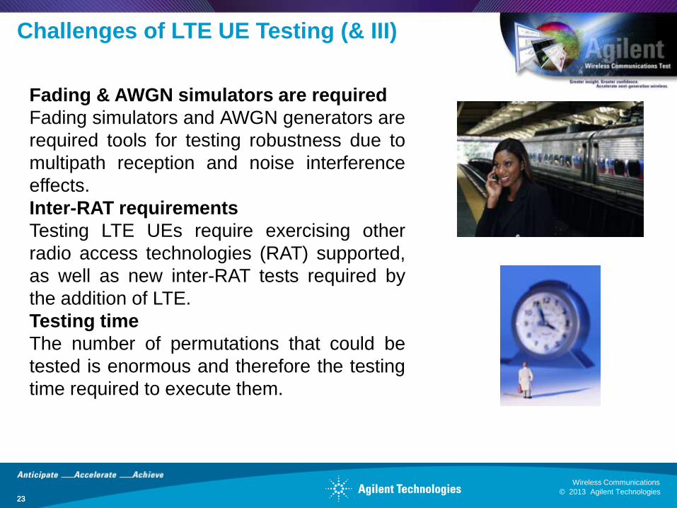
Fading & AWGN simulators are required
Fading simulators and AWGN generators are
required tools for testing robustness due to
multipath reception and noise interference
effects.
Inter-RAT requirements
Testing LTE UEs require exercising other
radio access technologies (RAT) supported,
as well as new inter-RAT tests required by
the addition of LTE.
Testing time
The number of permutations that could be
tested is enormous and therefore the testing
time required to execute them.
© 2013 Agilent Technologies
Wireless Communications
24 © 2013 Agilent Technologies
Wireless Communications
LTE RF Testing Definitions
24
3GPP TS 36.101 establishes the minimum RF characteristics and minimum
performance requirements for E-UTRA User Equipment (UE)
3GPP TS 36.521-1 specifies the measurement procedures for the conformance
Radio transmission and reception tests of the UE based on the requirements
established by the TS 36.101
Four different sets of Tests are defined classified by the block of functionality under
test:
Chapter 6: Transmitter Characteristics
Chapter 7: Receiver Characteristics
Chapter 8: Performance Requirement
Chapter 9: Reporting of Channel State Information
© 2013 Agilent Technologies
Wireless Communications
25 © 2013 Agilent Technologies
Wireless Communications
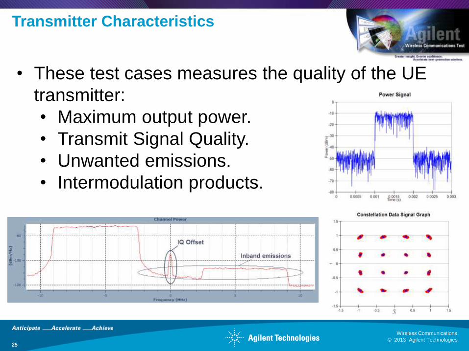
Transmitter Characteristics
25
• These test cases measures the quality of the UE
transmitter:
• Maximum output power.
• Transmit Signal Quality.
• Unwanted emissions.
• Intermodulation products.
© 2013 Agilent Technologies
Wireless Communications
26 © 2013 Agilent Technologies
Wireless Communications
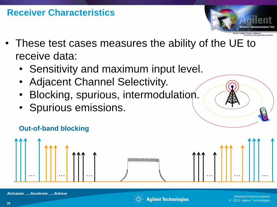
Receiver Characteristics
26
• These test cases measures the ability of the UE to
receive data:
• Sensitivity and maximum input level.
• Adjacent Channel Selectivity.
• Blocking, spurious, intermodulation.
• Spurious emissions.
… … … … … …
Out-of-band blocking
© 2013 Agilent Technologies
Wireless Communications
27 © 2013 Agilent Technologies
Wireless Communications
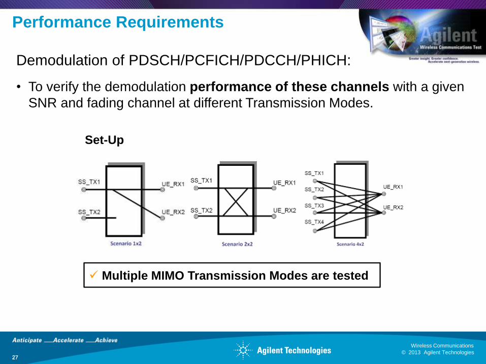
Performance Requirements
27
Demodulation of PDSCH/PCFICH/PDCCH/PHICH:
• To verify the demodulation performance of these channels with a given
SNR and fading channel at different Transmission Modes.
Set-Up
Multiple MIMO Transmission Modes are tested
© 2013 Agilent Technologies
Wireless Communications
28 © 2013 Agilent Technologies
Wireless Communications
Reporting of Channel State Information
28
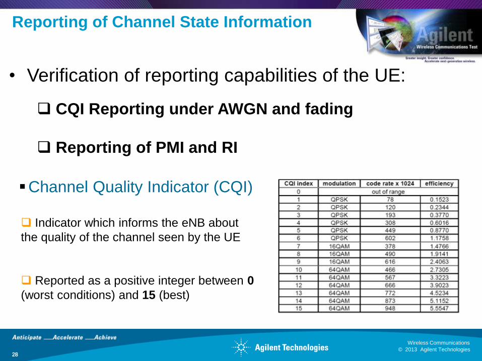
• Verification of reporting capabilities of the UE:
CQI Reporting under AWGN and fading
Reporting of PMI and RI
Indicator which informs the eNB about
the quality of the channel seen by the UE
Reported as a positive integer between 0
(worst conditions) and 15 (best)
Channel Quality Indicator (CQI)
© 2013 Agilent Technologies
Wireless Communications
29 © 2013 Agilent Technologies
Wireless Communications
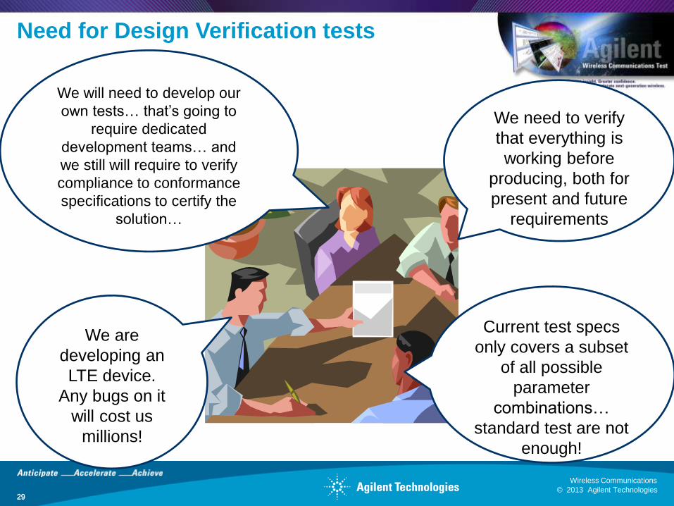
Need for Design Verification tests
29
We are
developing an
LTE device.
Any bugs on it
will cost us
millions!
We need to verify
that everything is
working before
producing, both for
present and future
requirements
Current test specs
only covers a subset
of all possible
parameter
combinations…
standard test are not
enough!
We will need to develop our
own tests… that’s going to
require dedicated
development teams… and
we still will require to verify
compliance to conformance
specifications to certify the
solution…
© 2013 Agilent Technologies
Wireless Communications
30 © 2013 Agilent Technologies
Wireless Communications
Design Verification RF tests
30
• DV tests address these needs by
providing:
• User-defined and customized
tests.
• Deeper parameterization than
conformance.
• More restricted pass/fail
criteria.
• Traceability with conformance
test cases (pre-conformance).
© 2013 Agilent Technologies
Wireless Communications
31 © 2013 Agilent Technologies
Wireless Communications
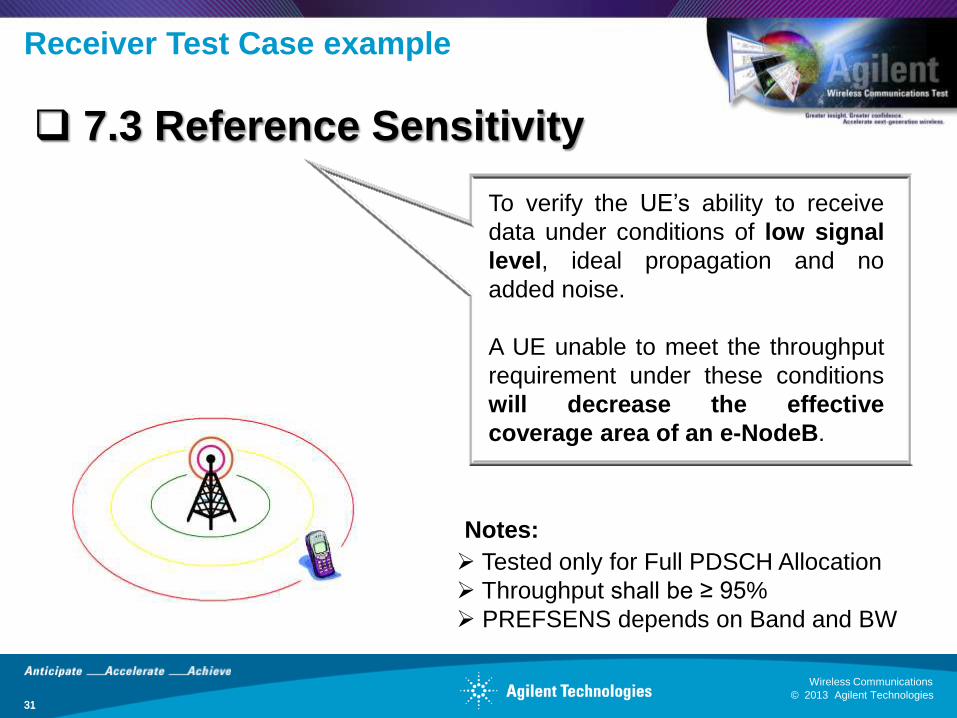
Receiver Test Case example
31
To verify the UE’s ability to receive
data under conditions of low signal
level, ideal propagation and no
added noise.
A UE unable to meet the throughput
requirement under these conditions
will decrease the effective
coverage area of an e-NodeB.
7.3 Reference Sensitivity
Tested only for Full PDSCH Allocation
Throughput shall be ≥ 95%
PREFSENS depends on Band and BW
Notes:
© 2013 Agilent Technologies
Wireless Communications
32 © 2013 Agilent Technologies
Wireless Communications
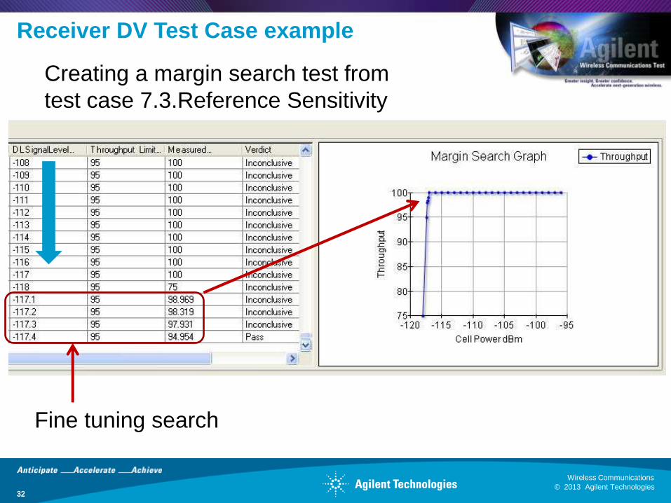
Receiver DV Test Case example
32
Creating a margin search test from
test case 7.3.Reference Sensitivity
Fine tuning search
© 2013 Agilent Technologies
Wireless Communications
33 © 2013 Agilent Technologies
Wireless Communications
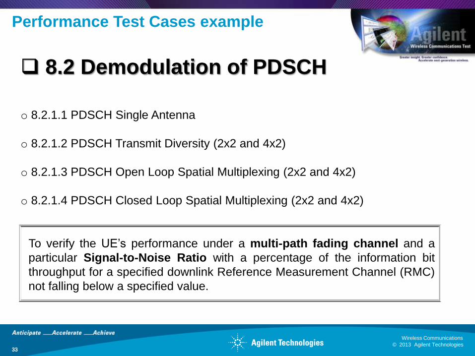
Performance Test Cases example
33
8.2 Demodulation of PDSCH
o 8.2.1.1 PDSCH Single Antenna
o 8.2.1.2 PDSCH Transmit Diversity (2x2 and 4x2)
o 8.2.1.3 PDSCH Open Loop Spatial Multiplexing (2x2 and 4x2)
o 8.2.1.4 PDSCH Closed Loop Spatial Multiplexing (2x2 and 4x2)
To verify the UE’s performance under a multi-path fading channel and a
particular Signal-to-Noise Ratio with a percentage of the information bit
throughput for a specified downlink Reference Measurement Channel (RMC)
not falling below a specified value.
© 2013 Agilent Technologies
Wireless Communications
34 © 2013 Agilent Technologies
Wireless Communications
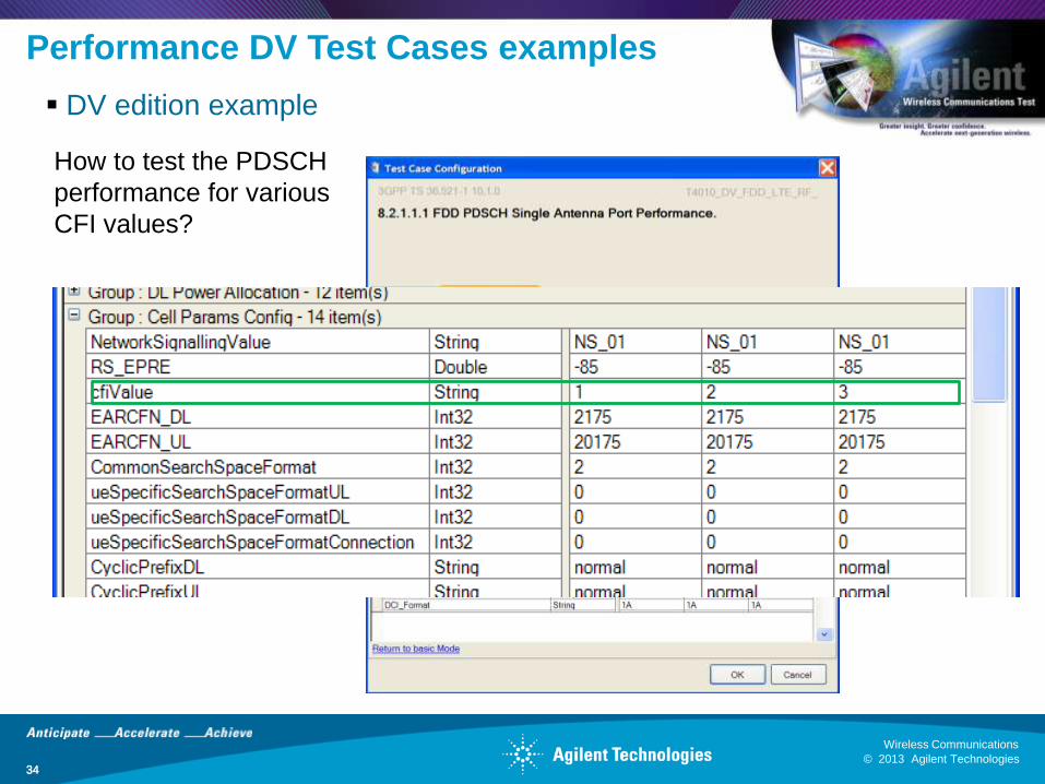
Performance DV Test Cases examples
34
DV edition example
How to test the PDSCH
performance for various
CFI values?
© 2013 Agilent Technologies
Wireless Communications
35 © 2013 Agilent Technologies
Wireless Communications
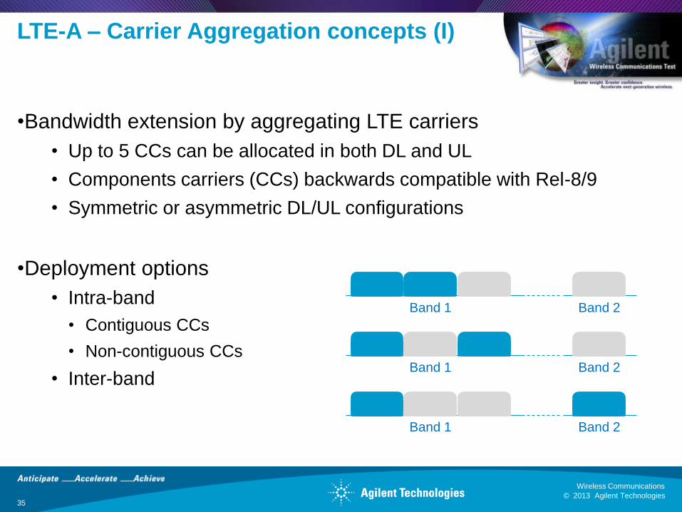
•Bandwidth extension by aggregating LTE carriers
• Up to 5 CCs can be allocated in both DL and UL
• Components carriers (CCs) backwards compatible with Rel-8/9
• Symmetric or asymmetric DL/UL configurations
•Deployment options
• Intra-band
• Contiguous CCs
• Non-contiguous CCs
• Inter-band
LTE-A – Carrier Aggregation concepts (I)
Band 1 Band 2
Band 1 Band 2
Band 1 Band 2

© 2013 Agilent Technologies
Wireless Communications
36 © 2013 Agilent Technologies
Wireless Communications
Test cases for Carrier Aggregation
36
All current test cases defined in Rel-10.
A few ‘sample’ band combinations were defined in Rel-10. Most
of the band combinations are defined in Rel-11.
Test cases defined for inter-band without UL CA and intra-band
contiguous with and without UL CA.
56 RF test cases defined.
16 RRM test cases defined.
36 Protocol test cases defined.
© 2013 Agilent Technologies
Wireless Communications
37 © 2013 Agilent Technologies
Wireless Communications
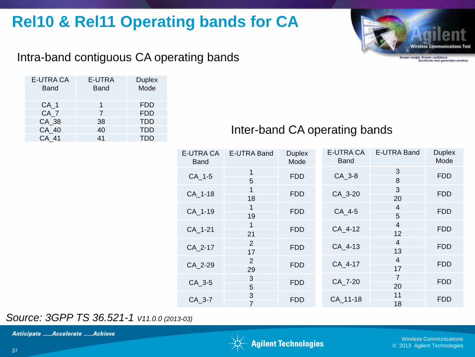
Rel10 & Rel11 Operating bands for CA
E-UTRA CA
Band
E-UTRA
Band
Duplex
Mode
CA_1 1 FDD
CA_7 7 FDD
CA_38 38 TDD
CA_40 40 TDD
CA_41 41 TDD
Intra-band contiguous CA operating bands
Inter-band CA operating bands
Source: 3GPP TS 36.521-1 V11.0.0 (2013-03)
E-UTRA CA
Band
E-UTRA Band Duplex
Mode
CA_1-5 1
FDD 5
CA_1-18 1
FDD 18
CA_1-19 1
FDD 19
CA_1-21 1
FDD 21
CA_2-17 2
FDD 17
CA_2-29 2
FDD 29
CA_3-5 3
FDD 5
CA_3-7 3
FDD 7
E-UTRA CA
Band
E-UTRA Band Duplex
Mode
CA_3-8 3
FDD 8
CA_3-20 3
FDD 20
CA_4-5 4
FDD 5
CA_4-12 4
FDD 12
CA_4-13 4
FDD 13
CA_4-17 4
FDD 17
CA_7-20 7
FDD 20
CA_11-18 11
FDD 18
© 2013 Agilent Technologies
Wireless Communications
38 © 2013 Agilent Technologies
Wireless Communications
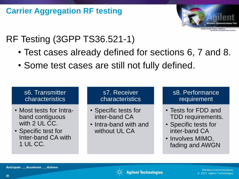
Carrier Aggregation RF testing
38
RF Testing (3GPP TS36.521-1)
• Test cases already defined for sections 6, 7 and 8.
• Some test cases are still not fully defined.
s6. Transmitter characteristics
• Most tests for Intra-band contiguous with 2 UL CC.
• Specific test for Inter-band CA with 1 UL CC.
s7. Receiver characteristics
• Specific tests for inter-band CA
• Intra-band with and without UL CA
s8. Performance requirement
• Tests for FDD and TDD requirements.
• Specific tests for inter-band CA
• Involves MIMO, fading and AWGN
© 2013 Agilent Technologies
Wireless Communications
39 © 2013 Agilent Technologies
Wireless Communications
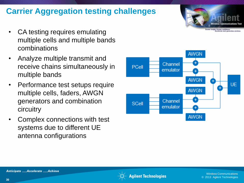
Carrier Aggregation testing challenges
39
• CA testing requires emulating
multiple cells and multiple bands
combinations
• Analyze multiple transmit and
receive chains simultaneously in
multiple bands
• Performance test setups require
multiple cells, faders, AWGN
generators and combination
circuitry
• Complex connections with test
systems due to different UE
antenna configurations
© 2013 Agilent Technologies
Wireless Communications
40 © 2013 Agilent Technologies
Wireless Communications
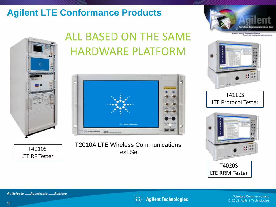
Agilent LTE Conformance Products
40
T4110S LTE Protocol Tester
T4020S LTE RRM Tester
ALL BASED ON THE SAME HARDWARE PLATFORM
T4010S LTE RF Tester
T2010A LTE Wireless Communications
Test Set

© 2013 Agilent Technologies
Wireless Communications
41 © 2013 Agilent Technologies
Wireless Communications
Questions?
41
© 2013 Agilent Technologies
Wireless Communications
42 © 2013 Agilent Technologies
Wireless Communications
Backup slides
42

© 2013 Agilent Technologies
Wireless Communications
43 © 2013 Agilent Technologies
Wireless Communications
Transmitter Test Cases
43
Clause Title
6.2.2 UE maximum output power
6.2.3 Maximum power reduction (MPR)
6.2.4 Additional maximum power reduction (A-MPR)
6.2.5 Configure UE transmitted output power
6.3.2 Minimum output power
6.3.4.1 General ON/OFF time mask
6.3.4.2.1 PRACH time mask
6.3.4.2.2 SRS time mask
6.3.5.1 Power control absolute power tolerance
6.3.5.2 Power Control Relative Power Tolerance
6.3.5.3 Aggregate power control tolerance
6.5.1 Frequency error
6.5.2.1 Error vector magnitude (EVM)
6.5.2.1A PUSCH-EVM with exclusion period
6.5.2.2 IQ component
6.5.2.3 In-band emissions for non allocated RBs
6.5.2.4 Spectrum flatness
6.6.1 Occupied bandwidth
6.6.2.1 Spectrum Emission Mask
6.6.2.2 Additional Spectrum Emission Mask
6.6.2.3 Adjacent Channel Leakage Power Ratio
6.6.3.1 Transmitter Spurious emissions
6.6.3.2 Spurious emission band UE co-existence
6.6.3.2-1 Spurious emission band UE co-existence (Rel-9)
6.6.3.3 Additional spurious emissions
6.7 Transmit intermodulation
© 2013 Agilent Technologies
Wireless Communications
44 © 2013 Agilent Technologies
Wireless Communications
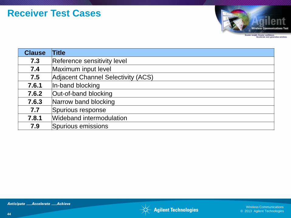
Receiver Test Cases
44
Clause Title
7.3 Reference sensitivity level
7.4 Maximum input level
7.5 Adjacent Channel Selectivity (ACS)
7.6.1 In-band blocking
7.6.2 Out-of-band blocking
7.6.3 Narrow band blocking
7.7 Spurious response
7.8.1 Wideband intermodulation
7.9 Spurious emissions
© 2013 Agilent Technologies
Wireless Communications
45 © 2013 Agilent Technologies
Wireless Communications
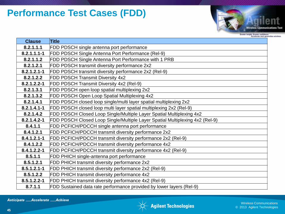
Performance Test Cases (FDD)
45
Clause Title
8.2.1.1.1 FDD PDSCH single antenna port performance
8.2.1.1.1-1 FDD PDSCH Single Antenna Port Performance (Rel-9)
8.2.1.1.2 FDD PDSCH Single Antenna Port Performance with 1 PRB
8.2.1.2.1 FDD PDSCH transmit diversity performance 2x2
8.2.1.2.1-1 FDD PDSCH transmit diversity performance 2x2 (Rel-9)
8.2.1.2.2 FDD PDSCH Transmit Diversity 4x2
8.2.1.2.2-1 FDD PDSCH Transmit Diversity 4x2 (Rel-9)
8.2.1.3.1 FDD PDSCH open loop spatial multiplexing 2x2
8.2.1.3.2 FDD PDSCH Open Loop Spatial Multiplexing 4x2
8.2.1.4.1 FDD PDSCH closed loop single/multi layer spatial multiplexing 2x2
8.2.1.4.1-1 FDD PDSCH closed loop multi layer spatial multiplexing 2x2 (Rel-9)
8.2.1.4.2 FDD PDSCH Closed Loop Single/Multiple Layer Spatial Multiplexing 4x2
8.2.1.4.2-1 FDD PDSCH Closed Loop Single/Multiple Layer Spatial Multiplexing 4x2 (Rel-9)
8.4.1.1 FDD PCFICH/PDCCH single antenna port performance
8.4.1.2.1 FDD PCFICH/PDCCH transmit diversity performance 2x2
8.4.1.2.1-1 FDD PCFICH/PDCCH transmit diversity performance 2x2 (Rel-9)
8.4.1.2.2 FDD PCFICH/PDCCH transmit diversity performance 4x2
8.4.1.2.2-1 FDD PCFICH/PDCCH transmit diversity performance 4x2 (Rel-9)
8.5.1.1 FDD PHICH single-antenna port performance
8.5.1.2.1 FDD PHICH transmit diversity performance 2x2
8.5.1.2.1-1 FDD PHICH transmit diversity performance 2x2 (Rel-9)
8.5.1.2.2 FDD PHICH transmit diversity performance 4x2
8.5.1.2.2-1 FDD PHICH transmit diversity performance 4x2 (Rel-9)
8.7.1.1 FDD Sustained data rate performance provided by lower layers (Rel-9)
© 2013 Agilent Technologies
Wireless Communications
46 © 2013 Agilent Technologies
Wireless Communications
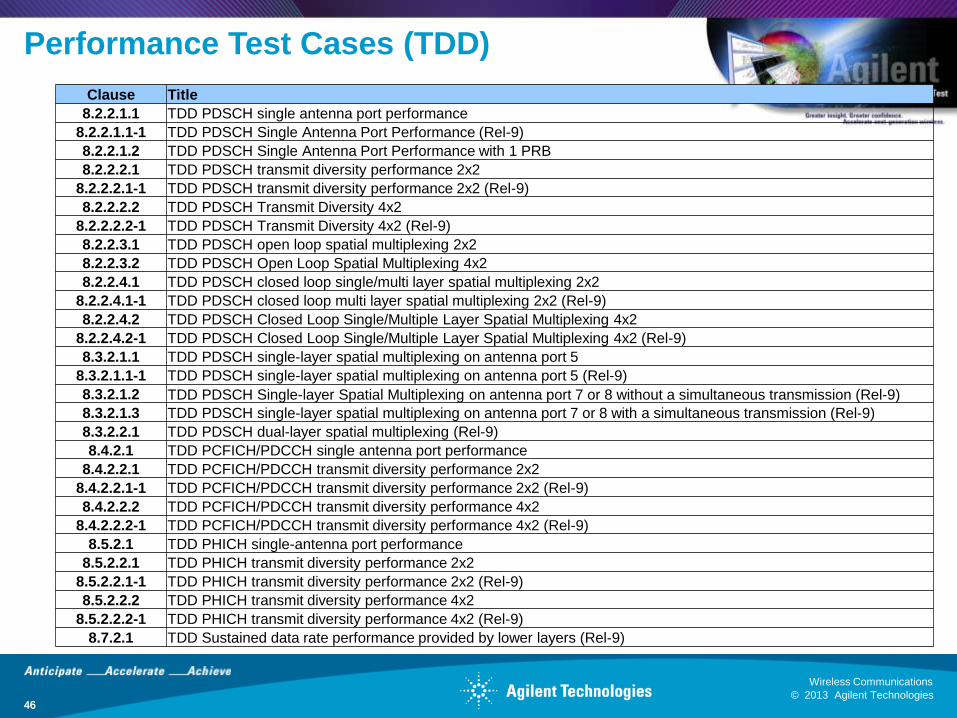
Performance Test Cases (TDD)
46
Clause Title
8.2.2.1.1 TDD PDSCH single antenna port performance
8.2.2.1.1-1 TDD PDSCH Single Antenna Port Performance (Rel-9)
8.2.2.1.2 TDD PDSCH Single Antenna Port Performance with 1 PRB
8.2.2.2.1 TDD PDSCH transmit diversity performance 2x2
8.2.2.2.1-1 TDD PDSCH transmit diversity performance 2x2 (Rel-9)
8.2.2.2.2 TDD PDSCH Transmit Diversity 4x2
8.2.2.2.2-1 TDD PDSCH Transmit Diversity 4x2 (Rel-9)
8.2.2.3.1 TDD PDSCH open loop spatial multiplexing 2x2
8.2.2.3.2 TDD PDSCH Open Loop Spatial Multiplexing 4x2
8.2.2.4.1 TDD PDSCH closed loop single/multi layer spatial multiplexing 2x2
8.2.2.4.1-1 TDD PDSCH closed loop multi layer spatial multiplexing 2x2 (Rel-9)
8.2.2.4.2 TDD PDSCH Closed Loop Single/Multiple Layer Spatial Multiplexing 4x2
8.2.2.4.2-1 TDD PDSCH Closed Loop Single/Multiple Layer Spatial Multiplexing 4x2 (Rel-9)
8.3.2.1.1 TDD PDSCH single-layer spatial multiplexing on antenna port 5
8.3.2.1.1-1 TDD PDSCH single-layer spatial multiplexing on antenna port 5 (Rel-9)
8.3.2.1.2 TDD PDSCH Single-layer Spatial Multiplexing on antenna port 7 or 8 without a simultaneous transmission (Rel-9)
8.3.2.1.3 TDD PDSCH single-layer spatial multiplexing on antenna port 7 or 8 with a simultaneous transmission (Rel-9)
8.3.2.2.1 TDD PDSCH dual-layer spatial multiplexing (Rel-9)
8.4.2.1 TDD PCFICH/PDCCH single antenna port performance
8.4.2.2.1 TDD PCFICH/PDCCH transmit diversity performance 2x2
8.4.2.2.1-1 TDD PCFICH/PDCCH transmit diversity performance 2x2 (Rel-9)
8.4.2.2.2 TDD PCFICH/PDCCH transmit diversity performance 4x2
8.4.2.2.2-1 TDD PCFICH/PDCCH transmit diversity performance 4x2 (Rel-9)
8.5.2.1 TDD PHICH single-antenna port performance
8.5.2.2.1 TDD PHICH transmit diversity performance 2x2
8.5.2.2.1-1 TDD PHICH transmit diversity performance 2x2 (Rel-9)
8.5.2.2.2 TDD PHICH transmit diversity performance 4x2
8.5.2.2.2-1 TDD PHICH transmit diversity performance 4x2 (Rel-9)
8.7.2.1 TDD Sustained data rate performance provided by lower layers (Rel-9)
© 2013 Agilent Technologies
Wireless Communications
47 © 2013 Agilent Technologies
Wireless Communications
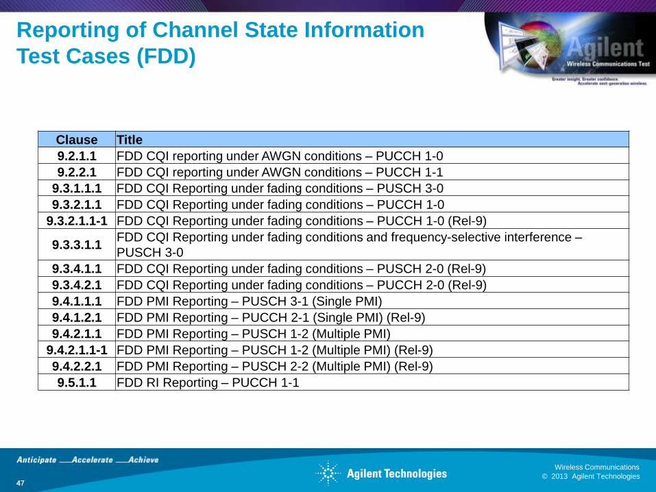
Reporting of Channel State Information
Test Cases (FDD)
47
Clause Title
9.2.1.1 FDD CQI reporting under AWGN conditions – PUCCH 1-0
9.2.2.1 FDD CQI reporting under AWGN conditions – PUCCH 1-1
9.3.1.1.1 FDD CQI Reporting under fading conditions – PUSCH 3-0
9.3.2.1.1 FDD CQI Reporting under fading conditions – PUCCH 1-0
9.3.2.1.1-1 FDD CQI Reporting under fading conditions – PUCCH 1-0 (Rel-9)
9.3.3.1.1 FDD CQI Reporting under fading conditions and frequency-selective interference –
PUSCH 3-0
9.3.4.1.1 FDD CQI Reporting under fading conditions – PUSCH 2-0 (Rel-9)
9.3.4.2.1 FDD CQI Reporting under fading conditions – PUCCH 2-0 (Rel-9)
9.4.1.1.1 FDD PMI Reporting – PUSCH 3-1 (Single PMI)
9.4.1.2.1 FDD PMI Reporting – PUCCH 2-1 (Single PMI) (Rel-9)
9.4.2.1.1 FDD PMI Reporting – PUSCH 1-2 (Multiple PMI)
9.4.2.1.1-1 FDD PMI Reporting – PUSCH 1-2 (Multiple PMI) (Rel-9)
9.4.2.2.1 FDD PMI Reporting – PUSCH 2-2 (Multiple PMI) (Rel-9)
9.5.1.1 FDD RI Reporting – PUCCH 1-1

© 2013 Agilent Technologies
Wireless Communications
48 © 2013 Agilent Technologies
Wireless Communications
Reporting of Channel State Information
Test Cases (TDD)
48
Clause Title
9.2.1.2 TDD CQI reporting under AWGN conditions – PUCCH 1-0
9.2.2.2 TDD CQI reporting under AWGN conditions – PUCCH 1-1
9.3.1.1.2 TDD CQI Reporting under fading conditions – PUSCH 3-0
9.3.2.1.2 TDD CQI Reporting under fading conditions – PUCCH 1-0
9.3.2.1.2-1 TDD CQI Reporting under fading conditions – PUCCH 1-0 (Rel-9)
9.3.3.1.2 TDD CQI Reporting under fading conditions and frequency-selective interference –
PUSCH 3-0
9.3.4.1.2 TDD CQI Reporting under fading conditions – PUSCH 2-0 (Rel-9)
9.3.4.2.2 TDD CQI Reporting under fading conditions – PUCCH 2-0 (Rel-9)
9.4.1.1.2 TDD PMI Reporting – PUSCH 3-1 (Single PMI)
9.4.1.2.2 TDD PMI Reporting – PUCCH 2-1 (Single PMI) (Rel-9)
9.4.2.1.2 TDD PMI Reporting – PUSCH 1-2 (Multiple PMI)
9.4.2.1.2-1 TDD PMI Reporting – PUSCH 1-2 (Multiple PMI) (Rel-9)
9.4.2.2.2 TDD PMI Reporting – PUSCH 2-2 (Multiple PMI) (Rel-9)
9.5.1.2 TDD RI Reporting – PUSCH 3-1
© 2013 Agilent Technologies
Wireless Communications
49 © 2013 Agilent Technologies
Wireless Communications
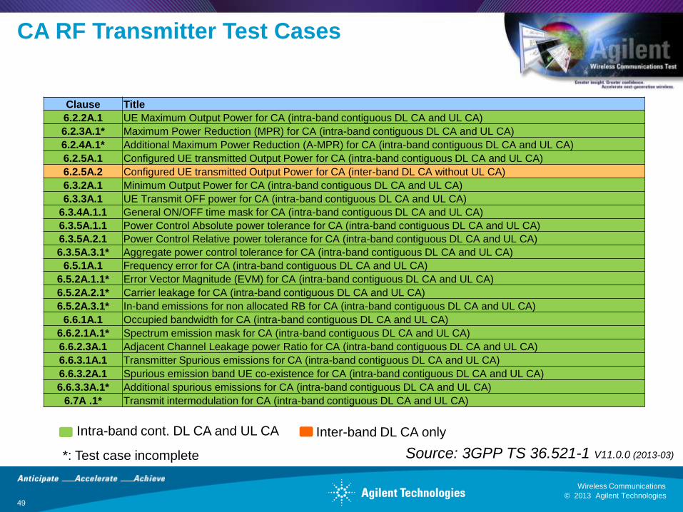
CA RF Transmitter Test Cases
Clause Title
6.2.2A.1 UE Maximum Output Power for CA (intra-band contiguous DL CA and UL CA)
6.2.3A.1* Maximum Power Reduction (MPR) for CA (intra-band contiguous DL CA and UL CA)
6.2.4A.1* Additional Maximum Power Reduction (A-MPR) for CA (intra-band contiguous DL CA and UL CA)
6.2.5A.1 Configured UE transmitted Output Power for CA (intra-band contiguous DL CA and UL CA)
6.2.5A.2 Configured UE transmitted Output Power for CA (inter-band DL CA without UL CA)
6.3.2A.1 Minimum Output Power for CA (intra-band contiguous DL CA and UL CA)
6.3.3A.1 UE Transmit OFF power for CA (intra-band contiguous DL CA and UL CA)
6.3.4A.1.1 General ON/OFF time mask for CA (intra-band contiguous DL CA and UL CA)
6.3.5A.1.1 Power Control Absolute power tolerance for CA (intra-band contiguous DL CA and UL CA)
6.3.5A.2.1 Power Control Relative power tolerance for CA (intra-band contiguous DL CA and UL CA)
6.3.5A.3.1* Aggregate power control tolerance for CA (intra-band contiguous DL CA and UL CA)
6.5.1A.1 Frequency error for CA (intra-band contiguous DL CA and UL CA)
6.5.2A.1.1* Error Vector Magnitude (EVM) for CA (intra-band contiguous DL CA and UL CA)
6.5.2A.2.1* Carrier leakage for CA (intra-band contiguous DL CA and UL CA)
6.5.2A.3.1* In-band emissions for non allocated RB for CA (intra-band contiguous DL CA and UL CA)
6.6.1A.1 Occupied bandwidth for CA (intra-band contiguous DL CA and UL CA)
6.6.2.1A.1* Spectrum emission mask for CA (intra-band contiguous DL CA and UL CA)
6.6.2.3A.1 Adjacent Channel Leakage power Ratio for CA (intra-band contiguous DL CA and UL CA)
6.6.3.1A.1 Transmitter Spurious emissions for CA (intra-band contiguous DL CA and UL CA)
6.6.3.2A.1 Spurious emission band UE co-existence for CA (intra-band contiguous DL CA and UL CA)
6.6.3.3A.1* Additional spurious emissions for CA (intra-band contiguous DL CA and UL CA)
6.7A .1* Transmit intermodulation for CA (intra-band contiguous DL CA and UL CA)
Intra-band cont. DL CA and UL CA Inter-band DL CA only
*: Test case incomplete Source: 3GPP TS 36.521-1 V11.0.0 (2013-03)

© 2013 Agilent Technologies
Wireless Communications
50 © 2013 Agilent Technologies
Wireless Communications
CA RF Receiver Test Cases
Clause Title
7.3A.1 Reference sensitivity level for CA (intra-band contiguous DL CA and UL CA)
7.3A.2 Reference sensitivity level for CA (intra-band contiguous DL CA without UL CA)
7.3A.3* Reference sensitivity level for CA (inter-band DL CA without UL CA)
7.4A.1 Maximum input level for CA (intra-band contiguous DL CA and UL CA)
7.4A.2 Maximum input level for CA (intra-band contiguous DL CA without UL CA)
7.5A.1 Adjacent Channel Selectivity (ACS) for CA (intra-band contiguous DL CA and UL CA)
7.5A.2 Adjacent Channel Selectivity (ACS) for CA (intra-band contiguous DL CA without UL CA)
7.5A.3* Adjacent Channel Selectivity (ACS) for CA (inter-band DL CA without UL CA)
7.6.1A.1 In-band blocking for CA (intra-band contiguous DL CA and UL CA)
7.6.1A.2 In-band blocking for CA (intra-band contiguous DL CA without UL CA)
7.6.1A.3 In-band blocking for CA (inter-band DL CA without UL CA)
7.6.2A.1 Out-of-band blocking for CA (intra-band contiguous DL CA and UL CA)
7.6.2A.2 Out-of-band blocking for CA (intra-band contiguous DL CA without UL CA)
7.6.2A.3* Out-of-band blocking for CA (inter-band DL CA without UL CA)
7.6.3A.1 Narrow band blocking for CA (intra-band contiguous DL CA and UL CA)
7.6.3A.2 Narrow band blocking for CA (intra-band contiguous DL CA without UL CA)
7.6.3A.3 Narrow band blocking for CA (inter-band DL CA without UL CA)
7.7A.1 Spurious response for CA (intra-band contiguous DL CA and UL CA)
7.7A.2 Spurious response for CA (intra-band contiguous DL CA without UL CA)
7.7A.3* Spurious response for CA (inter-band DL CA without UL CA)
7.8.1A.1* Wideband intermodulation for CA (intra-band contiguous DL CA and UL CA)
7.8.1A.2* Wideband intermodulation for CA (intra-band contiguous DL CA without UL CA)
7.8.1A.3* Wideband intermodulation for CA (inter-band DL CA without UL CA)
Intra-band cont. DL CA and UL CA Intra-band cont. DL CA only Inter-band DL CA only
*: Test case incomplete Source: 3GPP TS 36.521-1 V11.0.0 (2013-03)
© 2013 Agilent Technologies
Wireless Communications
51 © 2013 Agilent Technologies
Wireless Communications
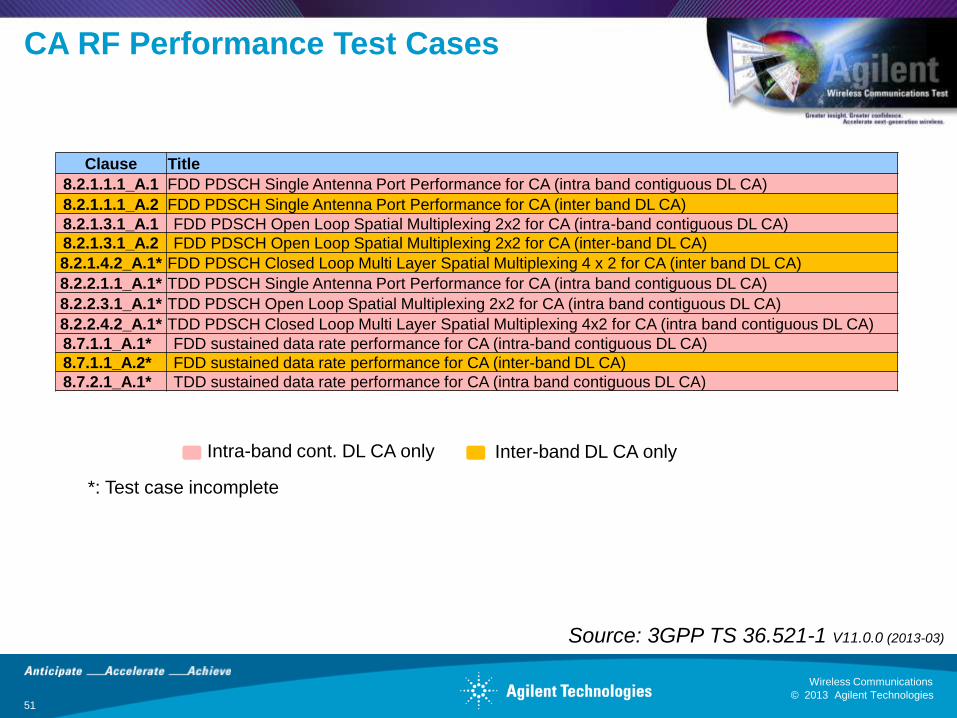
CA RF Performance Test Cases
Clause Title
8.2.1.1.1_A.1 FDD PDSCH Single Antenna Port Performance for CA (intra band contiguous DL CA)
8.2.1.1.1_A.2 FDD PDSCH Single Antenna Port Performance for CA (inter band DL CA)
8.2.1.3.1_A.1 FDD PDSCH Open Loop Spatial Multiplexing 2x2 for CA (intra-band contiguous DL CA)
8.2.1.3.1_A.2 FDD PDSCH Open Loop Spatial Multiplexing 2x2 for CA (inter-band DL CA)
8.2.1.4.2_A.1* FDD PDSCH Closed Loop Multi Layer Spatial Multiplexing 4 x 2 for CA (inter band DL CA)
8.2.2.1.1_A.1* TDD PDSCH Single Antenna Port Performance for CA (intra band contiguous DL CA)
8.2.2.3.1_A.1* TDD PDSCH Open Loop Spatial Multiplexing 2x2 for CA (intra band contiguous DL CA)
8.2.2.4.2_A.1* TDD PDSCH Closed Loop Multi Layer Spatial Multiplexing 4x2 for CA (intra band contiguous DL CA)
8.7.1.1_A.1* FDD sustained data rate performance for CA (intra-band contiguous DL CA)
8.7.1.1_A.2* FDD sustained data rate performance for CA (inter-band DL CA)
8.7.2.1_A.1* TDD sustained data rate performance for CA (intra band contiguous DL CA)
Intra-band cont. DL CA only Inter-band DL CA only
*: Test case incomplete
Source: 3GPP TS 36.521-1 V11.0.0 (2013-03)

© 2013 Agilent Technologies
Wireless Communications
52 © 2013 Agilent Technologies
Wireless Communications
Agilent T2010A LTE Wireless
Communications Test Set
52
Ready for CA:
• 2 CCs, up to
MIMO 4x2 each
• Combined or
independent
TX/RX
• Integrated channel emulator
(up to MIMO 4x2)
• AWGN generator
• Power level accuracy as
required by 3GPP test
standards
• UL measurements
• Sensitivity and receiver
performance measurements
• 2 independent LTE
cells in one box
solution
• RF, RRM and
Protocol
conformance test
cases
© 2013 Agilent Technologies
Wireless Communications
53 © 2013 Agilent Technologies
Wireless Communications
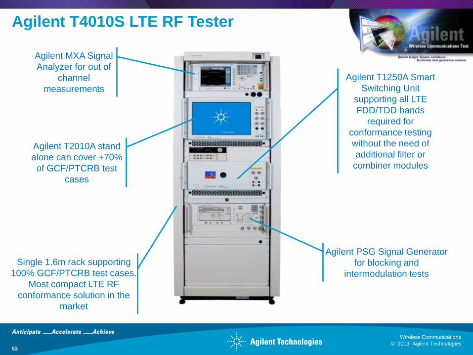
Agilent T4010S LTE RF Tester
53
Agilent T1250A Smart
Switching Unit
supporting all LTE
FDD/TDD bands
required for
conformance testing
without the need of
additional filter or
combiner modules
Single 1.6m rack supporting
100% GCF/PTCRB test cases.
Most compact LTE RF
conformance solution in the
market
Agilent PSG Signal Generator
for blocking and
intermodulation tests
Agilent MXA Signal
Analyzer for out of
channel
measurements
Agilent T2010A stand
alone can cover +70%
of GCF/PTCRB test
cases