prepared by: faculty advisors: program informationmet.sdsmt.edu/reu/2010report/carlson report.pdf2...
TRANSCRIPT

1
The Direct Reduction of Iron from its Ore Using Traditional Techniques
Prepared by:
Brett Carlson
Faculty Advisors:
Dr. William Cross
Associate Professor, Materials and Metallurgical Engineering Department
Dr. Jon Kellar
Department Head/Professor, Materials and Metallurgical Engineering Department
Dr. Alfred Boysen
Professor, Department of Humanities
Program Information:
National Science Foundation
Award # 0852057
Research Experience for Undergraduates
Site: Back to the Future
Summer 2010
South Dakota School of Mines and Technology
501 E Saint Joseph Street
Rapid City, SD 57701

2
Abstract
The direct reduction of iron from its ore was, for millennia, mankind’s primary source of
iron and steel. Historically, this process involved the heating of iron ore and a carbon source
under reducing conditions to produce metallic iron. The iron coalesces in the bottom of the
furnace in a porous mass, or bloom, which gives the “bloomery” process its name. Recently, a
resurgence of interest in this technique has occurred and direct reduction iron has become an
important piece in steel production. This study’s purpose is to further explore the ancient
techniques of iron production and to find ways to apply this information to current processes.
This will be accomplished by the construction, use, and analysis of a direct reduction furnace and
its products. Based on historical research and past experiments, the design of a low shaft
bloomery furnace was chosen. With the success of this furnace to produce iron, and the data
collected, it will be possible to obtain the conditions under which the iron was formed. It will
also be seen how furnace conditions affect the properties of the product.
3
1. Introduction
Since iron was first smelted sometime in the second millennium B.C.E. the special
qualities it possesses have been recognized by man as exceedingly useful. The history of this
material’s use and that of humanity seems closely tied, as the modern world we live in exists, in
no small part to the mass production of iron and its most useful alloy, steel. Historically though,
iron’s production was on a much smaller scale. For much of its history, iron was made in
furnaces that were born out of individual entrepreneurship and the effort of a small group of
people.[7] The main form of these furnaces was the bloomery. In it, iron ore and a carbon fuel,
most commonly charcoal, were heated under reducing conditions. At the correct temperature,
this led to the solid state reduction of iron ore into metallic iron. The result was a spongy mass
of iron and slag, or “bloom”, which had to be further processed to create a useful billet of iron.
[2] This product was used to make everything from swords to ploughshares. Eventually this
process evolved into the modern indirect process, involving the production of pig iron and its
decarburization to produce steel. In recent times, the direct reduction of iron has made a
comeback of sorts and is starting to play a role in the modern steelmaking process. This process
will be explored in its traditional form by the experimental operation of a bloomery furnace.
2. Broader Impact
The use of direct reduced iron (DRI) has become a viable source of “synthetic scrap” for
blast furnaces and a feedstock for steelmaking.[8] DRI plants have the potential to become an
important part of emerging economies where the funding for a modern blast furnace could be
hard to come by. This gives reason to explore the DRI process.
4
The historical aspects of DRI also merit exploration. The bloomery furnace was
humanity’s main source of iron for thousands of years, and there exists a responsibility for
modern society to understand and preserve that process.
This study in the direct reduction of iron, though seemingly small, expands the
knowledge of pre-industrial metallurgy and helps in the understanding of how this knowledge
may be applied in the future.
3. Procedure
3.1 Materials
Narcon 65 Castable refractory
Concrete forms
Cleveland Cliffs pellets
Furnace slag
Hammer scale
Charcoal
3.2 Equipment
High volume blower
Pyrometer
XRF Equipment
Metallurgical Microscope
3.3 Construction
The site of the furnace was chosen, on the criteria of convenience, levelness of surface,
and appropriate base material, to be a bed of compacted gravel. A square frame, 27”x27”, was
5
assembled out of wood. The frame was partially entrenched. A layer of fine silica sand was set
inside the frame to help support a firebrick base. Sand was swept into the joints of the brick to
hold these bricks in place. Forms were made to support the castable refractory that would make
up the walls of the furnace, which were in the shape of a hollow cylinder. The inner form
consisted of a commercially available concrete form 30 cm in diameter. The outer form was
constructed out sheet metal of wrapped and fastened in a way that made a cylinder with a
diameter of 40 cm. Both of these were slightly over 60 cm in height. A cylindrical grid of
reinforcing wire made from fencing material was placed between the outer and inner forms to
provide reinforcement. Cardboard tubes were placed inside the forms as placeholders for the
tuyere and slag tapping hole. The refractory used was Narcon 65 castable refractory donated by
Grupo Cementos de Chihuahua (GCC). The castable refractory was mixed in a wheelbarrow
using a flat bladed shovel, with water added until the desired consistency was achieved. It was
then poured into the forms and allowed to cure over a period of three days. Once the forms were
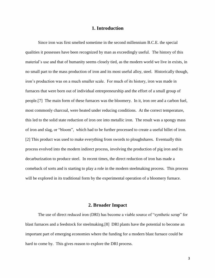
removed, the tuyere and slag holes were enlarged through the use of a masonry drill bit. A grid
of reinforcing wire was secured on the outside of the furnace to provide support, see figure 1. In
order to fully cure the refractory it was necessary to heat it to a point under operating
temperature and hold it there for a number of hours. To accomplish this, a wood fire was started
in the furnace and allowed to burn without an air blast. When the walls of the furnace reached
three hundred degrees, the temperature was maintained for three and a half hours. The dry out
resulted in some minor cracking of the furnace walls, but nothing considered detrimental to its
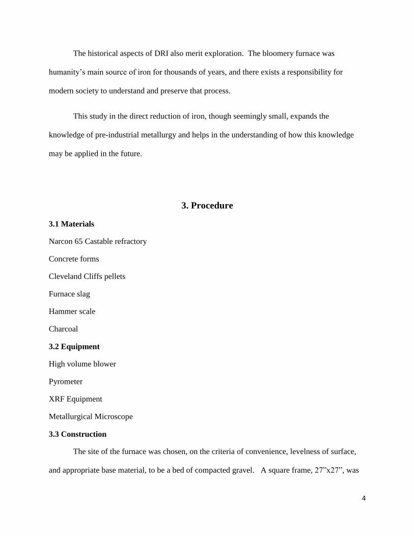
integrity. Following the dry out, firebrick was set around the furnace to provide increased
insulation, as shown in figure 2.
6
Figure 1-Interior furnace lining Figure 2-Furnace exterior
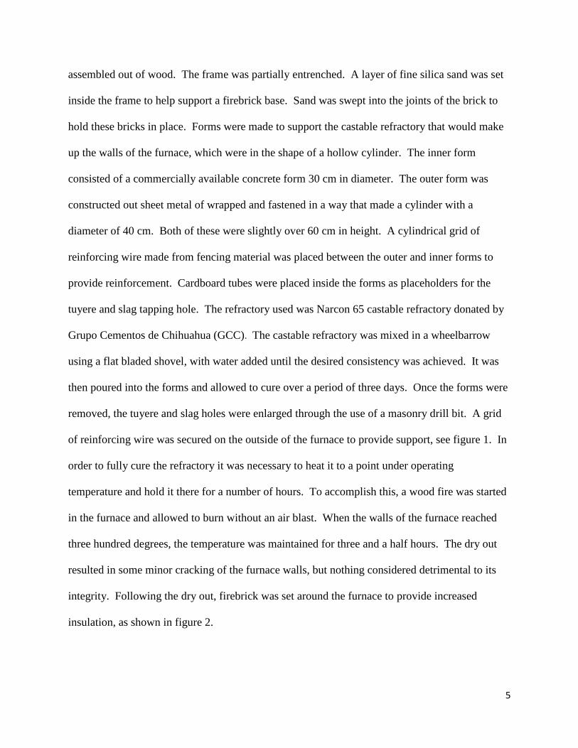
For the air supply for the furnace, a high volume electric blower was used. A gate was
fabricated to fit on the blower intake to regulate air flow. The output diameter of the blower was
reduced and ran through a section of flexible pipe. From there it intersected with a T pipe fitting
as shown in fugue three. One end of the T went to the tuyere and the other was closed with a
removable end cap to facilitate the cleaning out of the tuyere if necessary during the furnace run.
The portion of the tuyere that went into the furnace consisted of a copper tube 2.54 centimeters
in diameter, which was coated with a refractory of red clay and silica sand.
Figure 3- Furnace air supply equipment
7
3.4 Operation
Before the furnace could be fired, various preparation tasks had to be performed. The first
was the classification of charcoal. A commercial natural hardwood charcoal was selected. Any
pieces exceeding 3 cm in diameter were broken up, and all the charcoal was run through a screen
to sort out any “fines.” The ore also had to be broken up. Primary crushing was done with a
hammer and chisel until the pieces were no bigger than 4 cm in diameter. The ore was then put
through a jaw crusher that brought the pieces to about a centimeter in diameter. At this point the
ore was put through the roll crusher and reduced to the size of rough sand. Two kilogram
charges of charcoal were then measured and placed in bags.
A bed of charcoal fines was placed in the furnace to allow the bloom a place to settle into
and to help in its removal. A wood fire was then stated in the furnace and allowed to burn
without an air blast for forty-five minutes. At this point, a charge charcoal was put in and the air
blast turned on. As the charcoal lit another two kilogram charge was place on top, and a few
minutes later one more to fill the furnace. Once the entire burden was burning, a four kilogram
charge of half charcoal and half crushed furnace slag was added. A similar charge was added as
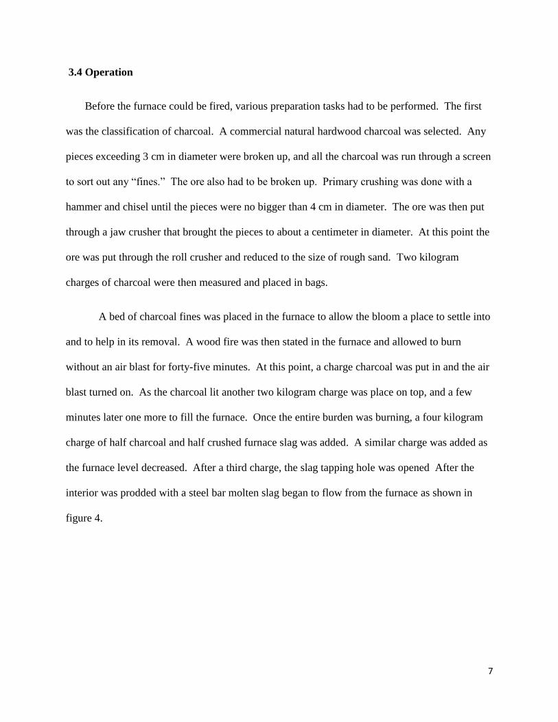
the furnace level decreased. After a third charge, the slag tapping hole was opened After the
interior was prodded with a steel bar molten slag began to flow from the furnace as shown in
figure 4.
8
Fig.4-Slag tap
Once the flowing ceased, a clay ball was placed in front of the slag tapping arch. Slag began to
build up in front of the tuyere, and a steel rod was put through the tuyere to clean it. After
another furnace charge, the tuyere was one again cleaned, but the terra-cotta end of the tuyere
which acted as a reducing coupling was damaged. The damaged piece was quickly replaced by a
back-up tuyere made of steel pipe. Another charge of ore was added but the furnace’s
consumption rate had slowed significantly. Slag blockage necessitated the cleaning of tuyere
more often and eventually the air blast was reduced to the point that the furnaces operating
temperature became low enough for the slag to begin to solidify. At this point the contents of the
furnace were be emptied before the furnace contents completely solidified. The slag and
charcoal were emptied through the slag tapping hole and quenched in water, and the furnace run
was concluded.
Because of the unsatisfactory results of the first attempt, a second furnace run was
performed. The furnace was prepped in a similar fashion than in the first. After the pre-heat
eight kilograms of charcoal were added to fill the furnace and bring it up to temperature. A
small ore charge of crushed pellets was added evenly onto the top load of charcoal. Alternating
layers of charcoal and ore were placed in the furnace at a ratio of 2 to 1, respectively, as the
furnace burden lowered. This was continued until 4.87 kilograms of pellets were added. After
that, 1.2 kilograms of hammer scale were added in two charges, one being 1 kilo and the other
9
0.2 k. A 2 kilogram charge of charcoal was placed on top of this hammer-scale and allowed to
burn down. When the furnace burden had reached 1/3 capacity, the extraction process began.
The bloom was found sticking to the wall of the furnace below the tuyere. At that point it was
dislodged by the use of a large wooden post. The bloom was withdrawn from the furnace by the
use of crucible tongs. The process of consolidating the bloom was then started with hammer and
wooden block. The bloom was returned to the furnace in between several consolidations of the
bloom.
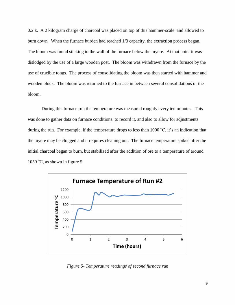
During this furnace run the temperature was measured roughly every ten minutes. This
was done to gather data on furnace conditions, to record it, and also to allow for adjustments
during the run. For example, if the temperature drops to less than 1000 oC, it’s an indication that
the tuyere may be clogged and it requires cleaning out. The furnace temperature spiked after the
initial charcoal began to burn, but stabilized after the addition of ore to a temperature of around
1050 oC, as shown in figure 5.
Figure 5- Temperature readings of second furnace run
0
200
400
600
800
1000
1200
0 1 2 3 4 5 6
Tem
pe
ratu
re o
C
Time (hours)
Furnace Temperature of Run #2
10
5.5 Testing
Testing was done on the consolidated bloom, see figure 6, as well as a portion of the
bloom that had not been consolidated. A small piece of the consolidated bloom was mounted,
polished and etched with a nital solution. A piece of the unconsolidated bloom was also polished
and etched. These were placed under microscope to observe their structure. The bloom was also
analyzed using x-ray fluorescence equipment to determine its metallurgical composition.
4. Results
4.1 Construction
The result of construction was a workable low shaft bloomery furnace. The inner walls
of the furnace were slightly deformed due to the inner form losing structural integrity when the
concrete was poured. The result was that the furnace had a slightly ovoid inner diameter. It was
discovered that simple red clay mixed with sand can make a suitable patching refractory with
some degree of strength.
4.2 Operation
Products of the first run were a free-flowing slag and partially reduced ore that formed
as a solid furnace slag. The second run resulted in an iron rich bloom. The repeated
consolidation of the bloom led to a product of a much higher density than the parent material, see
figure 9. During this process, a piece of the bloom was broken off which amounted to roughly
one third of its volume. This section was kept in an unconsolidated state for further testing, see
figure 8.
11
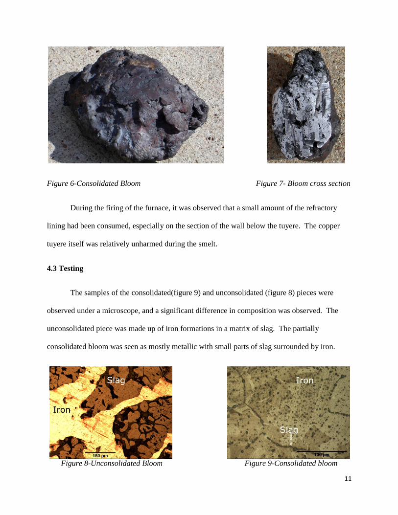
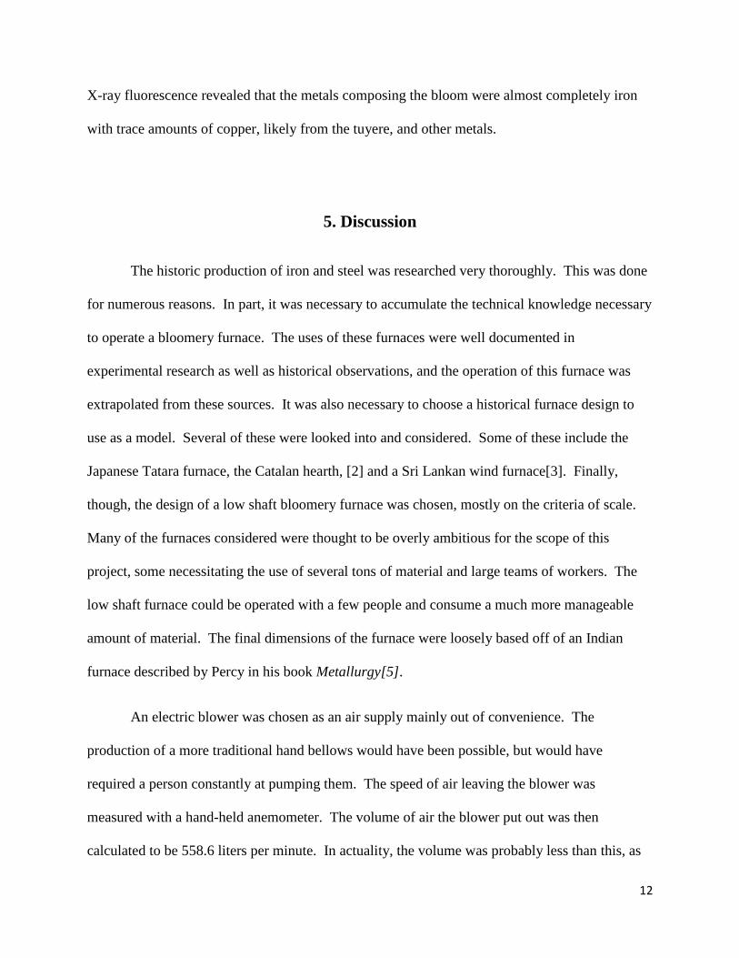
Figure 6-Consolidated Bloom Figure 7- Bloom cross section
During the firing of the furnace, it was observed that a small amount of the refractory
lining had been consumed, especially on the section of the wall below the tuyere. The copper
tuyere itself was relatively unharmed during the smelt.
4.3 Testing
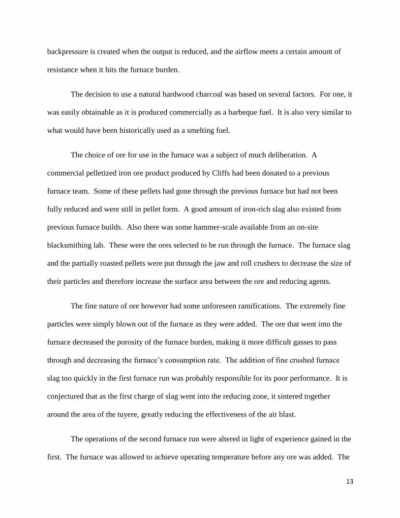
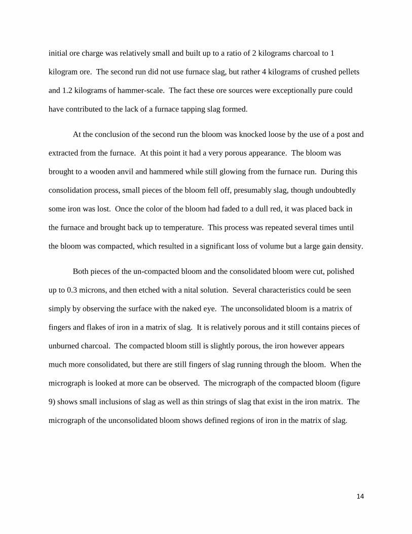
The samples of the consolidated(figure 9) and unconsolidated (figure 8) pieces were
observed under a microscope, and a significant difference in composition was observed. The
unconsolidated piece was made up of iron formations in a matrix of slag. The partially
consolidated bloom was seen as mostly metallic with small parts of slag surrounded by iron.
Figure 8-Unconsolidated Bloom Figure 9-Consolidated bloom
12
X-ray fluorescence revealed that the metals composing the bloom were almost completely iron
with trace amounts of copper, likely from the tuyere, and other metals.
5. Discussion
The historic production of iron and steel was researched very thoroughly. This was done
for numerous reasons. In part, it was necessary to accumulate the technical knowledge necessary
to operate a bloomery furnace. The uses of these furnaces were well documented in
experimental research as well as historical observations, and the operation of this furnace was
extrapolated from these sources. It was also necessary to choose a historical furnace design to
use as a model. Several of these were looked into and considered. Some of these include the
Japanese Tatara furnace, the Catalan hearth, [2] and a Sri Lankan wind furnace[3]. Finally,
though, the design of a low shaft bloomery furnace was chosen, mostly on the criteria of scale.
Many of the furnaces considered were thought to be overly ambitious for the scope of this
project, some necessitating the use of several tons of material and large teams of workers. The
low shaft furnace could be operated with a few people and consume a much more manageable
amount of material. The final dimensions of the furnace were loosely based off of an Indian
furnace described by Percy in his book Metallurgy[5].
An electric blower was chosen as an air supply mainly out of convenience. The
production of a more traditional hand bellows would have been possible, but would have
required a person constantly at pumping them. The speed of air leaving the blower was
measured with a hand-held anemometer. The volume of air the blower put out was then
calculated to be 558.6 liters per minute. In actuality, the volume was probably less than this, as
13
backpressure is created when the output is reduced, and the airflow meets a certain amount of
resistance when it hits the furnace burden.
The decision to use a natural hardwood charcoal was based on several factors. For one, it
was easily obtainable as it is produced commercially as a barbeque fuel. It is also very similar to
what would have been historically used as a smelting fuel.
The choice of ore for use in the furnace was a subject of much deliberation. A
commercial pelletized iron ore product produced by Cliffs had been donated to a previous
furnace team. Some of these pellets had gone through the previous furnace but had not been
fully reduced and were still in pellet form. A good amount of iron-rich slag also existed from
previous furnace builds. Also there was some hammer-scale available from an on-site
blacksmithing lab. These were the ores selected to be run through the furnace. The furnace slag
and the partially roasted pellets were put through the jaw and roll crushers to decrease the size of
their particles and therefore increase the surface area between the ore and reducing agents.
The fine nature of ore however had some unforeseen ramifications. The extremely fine
particles were simply blown out of the furnace as they were added. The ore that went into the
furnace decreased the porosity of the furnace burden, making it more difficult gasses to pass
through and decreasing the furnace’s consumption rate. The addition of fine crushed furnace
slag too quickly in the first furnace run was probably responsible for its poor performance. It is
conjectured that as the first charge of slag went into the reducing zone, it sintered together
around the area of the tuyere, greatly reducing the effectiveness of the air blast.
The operations of the second furnace run were altered in light of experience gained in the
first. The furnace was allowed to achieve operating temperature before any ore was added. The
14
initial ore charge was relatively small and built up to a ratio of 2 kilograms charcoal to 1
kilogram ore. The second run did not use furnace slag, but rather 4 kilograms of crushed pellets
and 1.2 kilograms of hammer-scale. The fact these ore sources were exceptionally pure could
have contributed to the lack of a furnace tapping slag formed.
At the conclusion of the second run the bloom was knocked loose by the use of a post and
extracted from the furnace. At this point it had a very porous appearance. The bloom was
brought to a wooden anvil and hammered while still glowing from the furnace run. During this
consolidation process, small pieces of the bloom fell off, presumably slag, though undoubtedly
some iron was lost. Once the color of the bloom had faded to a dull red, it was placed back in
the furnace and brought back up to temperature. This process was repeated several times until
the bloom was compacted, which resulted in a significant loss of volume but a large gain density.
Both pieces of the un-compacted bloom and the consolidated bloom were cut, polished
up to 0.3 microns, and then etched with a nital solution. Several characteristics could be seen
simply by observing the surface with the naked eye. The unconsolidated bloom is a matrix of
fingers and flakes of iron in a matrix of slag. It is relatively porous and it still contains pieces of
unburned charcoal. The compacted bloom still is slightly porous, the iron however appears
much more consolidated, but there are still fingers of slag running through the bloom. When the
micrograph is looked at more can be observed. The micrograph of the compacted bloom (figure
9) shows small inclusions of slag as well as thin strings of slag that exist in the iron matrix. The
micrograph of the unconsolidated bloom shows defined regions of iron in the matrix of slag.
15
6. Conclusion
Summary
In this project, the ancient methods of producing iron and steel were investigated. Based on this
research a low shaft bloomery furnace was designed and built. The furnace was operated and its
products extracted. The result was the production of a metallic “bloom” which was further
processed by compaction under a hammer. The products were then tested and found to be
metallic iron. The micrographs of the bloom before and after compaction show it was
significantly consolidated.
Future Work
There is much to be done in the way of future work. Several more runs of the furnace
should be done in order to better understand the techniques and skills involved in its operation.
Once there exists a good understanding of how the furnace performs, the size of the furnace
should be scaled up in order to process a larger amount of material and increase the amount of
furnace product. An existing furnace could be modified to increase efficiency and productivity.
The furnace conditions should also be further quantified. This could be accomplished by
several methods. A high temperature, high durability thermocouple should be acquired in order
to constantly and automatically measure the furnace temperature. An oxygen sensor should also
be installed to insure a reducing atmosphere is maintained during operation. This sensor is
available commercially but due to its high expense, it may be more feasible to construct one, as
this can be accomplished using an oxygen sensor salvaged from an automobile. A manometer
could also be installed to measure the internal pressure of the furnace. These additions would
16
significantly increase how efficiently the furnace operates and help to quantify furnace
conditions.
The recreating of historical methods of producing iron and steel should also be further
explored. A major part of this would be the use of period materials. A large part of this is to
locate and use an iron ore similar to what may have been used historically. Ideally, this would be
a local iron ore that could easily be gathered. Also a period refractory material and traditionally
supplied air blast could be used. This would more closely replicate the traditional methods of
iron production.
References
[1] Aitchingson, L. (1960). A history of metals. New York: Interscience Publishers, Inc.
[2] Craddock, P.T. (1995). Early metal mining and production. Edinburgh, U.K.: Edinburgh
University Press Ltd.
[3] Juleff, G. (1998). Early iron and steel in Sri Lanka. Mainz am Rhein : Philipp von Zabern.
[4] Prakash, B. (1991). Metallurgy of iron and steel making and blacksmithy in ancient India.
Indian Journal of History of Science, 26(4), 351-371.
[5] Percy, J. (1864). Metallurgy. London: John Murray
[6] Senn, M., Gfeller, U., Gue'nette-Beck, B., Lienemann, P., & Ulrich, A. (2010). Tools to
qualify experiments with bloomery furnaces. Archaeometry, 52(1), 131-145
[7] Tylecote, R.F. (1976). A history of metallurgy. London: The Metals Society.

17
[8] United States Steel. (1985). The making shaping and treating of steel. Pittsburgh:
Association of Iron and Steel Engineers.
Acknowledgements
The National Science Foundation provided is thanked for the funding that made this research
possible. A huge thank you is due to advisors Dr. Jon Kellar and Dr. William Cross for their
guidance, Dr. Stanley Howard for use of his extensive knowledge of steelmaking, the REU site
director Dr. Michael West for his role in putting the whole thing together, Professor of English
Dr. Alfred Boysen for his teaching and guidance in writing and speaking, Mr. Eric Young, my
brother Erik Carlson, and the faculty and staff of SDSM&T for all their help in accomplishing
this research project.