preparation and characterization of ultrathin palladium membranes
TRANSCRIPT

Preparation and Characterization of Ultrathin Palladium Membranes
X. Li,*,† T. M. Liu,† D. Huang,‡ Y. Q. Fan,‡ and N. P. Xu‡
College of Chemical Engineering, Shenyang Institute of Chemical Technology, Shenyang 110142, China, andCollege of Chemistry and Chemical Engineering and Key Laboratory of Material-Oriented ChemicalEngineering of Jiangsu ProVince and MOE, Nanjing UniVersity of Technology, Nanjing 210009, China
An ultrathin palladium membrane (1 µm) has been prepared by an improved photocatalytic deposition (PCD)pretreatment and the electroless modification method. SEM results demonstrated good adhesion of the platedpalladium membrane on the porous composite TiO2 support and dense coalescence of the palladium membrane.The flux and H2/N2 selectivity of the palladium membrane were determined in the temperature range of623-823 K and the pressure difference range of 0.02-0.15 MPa. At 673 K and 0.1 MPa pressure difference,the hydrogen permeation flux of the composite membrane was as high as 0.27 mol m-2 s-1, and the H2/N2
selectivity coefficient was 361. In this study, the activation energy of hydrogen permeation through thecomposite palladium membrane was 17 kJ/mol. The corrected pressure exponent for the palladium compositemembrane was nearly 0.8 deviated from Sievert’s law.
1. Introduction
In recent years, the demand for highly pure hydrogen hasincreased rapidly because of its use in many fields such assemiconductor manufacturing and petrochemical processing.1
Palladium composite membranes are receiving much attentionbecause of their ideal permeability and permselectivity towardhydrogen. Some methods have been proposed and developedto prepare palladium membranes including chemical vapordeposition (CVD),2 sputter coating,3 electroless plating,4 andelectrochemical plating,5 among others. The technique ofelectroless plating is one of the most popular methods ofpreparing palladium composite membranes because of its goodperformance. Prior to electroless plating, the membrane surfaceneeds to be activated to provide catalysis centers for the platingprocess. A two-step process has been used with palladium saltand tin chloride salt. However, widespread use of electrolesstechnologies is constrained primarily by cumbersome pretreat-ment process. In addition, the presence of tin compounds inthe sensitization procedure can cause the formation of pinholes.The adhesion between the metallic membrane and the substrateis also questionable. Many improvements in the activationprocedure have been developed. For example, Paglieri and Way6
reported a new activation procedure not only with osmosispressure but also using palladium acetate instead of palladiumchloride. Zhao et al.7 modified the electroless plating procedurewith boehmite gel activation on a porous alumina substrate inwhich the boehmite gel coating must be treated with hydrogenat 773 K to reduce the palladium. By these methods, both thetwo-step activation process and the tin impurities can be avoided.
In this study, a simple and valuable activation procedurecalled photocatalytic deposition (PCD) was established8 thatinvolved a photocatalytic reaction at the interface between aTiO2 semiconductor tube and a Pd(II) liquid film initiated bydirect irradiation. Conducting the reaction processes in a liquidfilm at room temperature, instead of in solution as in earliermethods, effectively avoided a homogeneous reaction and theintroduction of impurities throughout the bath. Then, the tubesupport activated by PCD was further modified by electroless
plating. The performances of the resulting palladium membraneswere also investigated. The technique can be characterized byboth the easy control of the uniformly packed palladiummembrane and the simplicity of the process.
2. Experimental Section
2.1. Palladium Membrane Preparation. The surface of bothends of a ZrO2-Al2O3 tubular support was coated with glaze,and the porous part left for the palladium membrane was fixedat 5 cm in length. One end of the tubular support was also closedwith glaze. The coating of the TiO2 layer on the ZrO2-Al2O3
tubular support was done by a method reported elsewhere.9 Thespecifications of TiO2 supports are listed in Table 1. The PCDprocess on the outer tube surface was carried out on aphotocatalytic setup (see Figure 1).8 A 160-W ultraviolet lamp(254.6 nm) was located about 50 mm away from the tubularTiO2 membrane. The PCD bath contained PdCl2, deionizedwater, HCl, and ethylene diamine tetraacetate (EDTA). Inaddition, the pH value of the reaction bath ranged between 2and 3 in order to prohibit the hydrolysis of PdCl2. Prior toirradiation, the TiO2 support was immersed into the PCD bathand maintained for 0.5 h to allow sufficient adsorption of thePCD bath onto the titania surface. Then, the TiO2 membranewas lifted out of the reaction solution, and a thin liquid filmformed on the TiO2 surface. The liquid film coating was directlyirradiated at room temperature for 1 h. At the same time, thesupport was rotated slowly with electric motor [0.00833 Hz (0.5rpm)] for uniform incidence of the radiation.
After photocatalytic pretreatment, the derived TiO2 membranewith palladium nuclei was removed and cleaned with distilledwater. The palladium was deposited from an ammine solutionstabilized with EDTA using hydrazine as the reducing agent.The composition and conditions of the electroless bath are listedin Table 2. After a given time, the deposits were washed withdeionized water and dried.
* To whom correspondence should be addressed. Tel.: +86-24-8938-3902. Fax: +86-24-8938-3760. E-mail: [email protected].
† Shenyang Institute of Chemical Technology.‡ Nanjing University of Technology.
Table 1. Specification of Supports
supporttube
diameter (mm)thickness
(mm)pore
size (nm)length(mm)
ZrO2-Al2O3 support 12 3 200 330TiO2 membrane 12 0.007 70 50
Ind. Eng. Chem. Res. 2009, 48, 2061–2065 2061
10.1021/ie8004644 CCC: $40.75 2009 American Chemical SocietyPublished on Web 12/29/2008
2.2. Palladium Membrane Characterization. The morphol-ogy and elemental composition of the palladium membrane andthe pore size distribution of the support were examined with afield-emission scanning electron microscope (LEO 1530 VPsystem, with an energy-dispersive detector; LEO Elektronen-mikroskopie GmbH, Oberkochen, Germany) and a gas-bubblepressure apparatus, respectively.
2.3. High-Temperature Gas Permeation Measurements.The gas permeation through the palladium membranes wasmeasured on the apparatus illustrated in Figure 2. One end ofthe obtained membrane was closed, and the other was fittedwith Teflon gaskets; the membrane was then was placed insidea stainless steel permeation cell. The separation area was 18.84cm2, the permeate side was kept at atmospheric pressure withH2 or N2 (99.999% each), and the seal was kept outside thefurnace. The upstream pressure was controlled with a back-pressure regulator. After stabilization of the temperature andpressure, single gas fluxes were measured with mass flowcontrollers (model D08-4D/ZM, Beijing Sevenstar HuachuangElectonic Co., Ltd., Beijing, China).
3. Results and Discussion
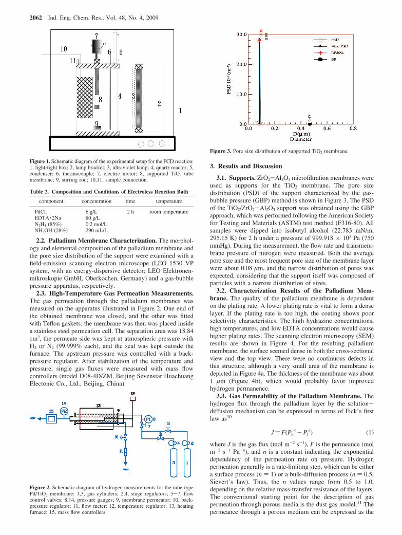
3.1. Supports. ZrO2-Al2O3 microfiltration membranes wereused as supports for the TiO2 membrane. The pore sizedistribution (PSD) of the support characterized by the gas-bubble pressure (GBP) method is shown in Figure 3. The PSDof the TiO2/ZrO2-Al2O3 support was obtained using the GBPapproach, which was performed following the American Societyfor Testing and Materials (ASTM) test method (F316-80). Allsamples were dipped into isobutyl alcohol (22.783 mN/m,295.15 K) for 2 h under a pressure of 999.918 × 10² Pa (750mmHg). During the measurement, the flow rate and transmem-brane pressure of nitrogen were measured. Both the averagepore size and the most frequent pore size of the membrane layerwere about 0.08 µm, and the narrow distribution of pores wasexpected, considering that the support itself was composed ofparticles with a narrow distribution of sizes.
3.2. Characterization Results of the Palladium Mem-brane. The quality of the palladium membrane is dependenton the plating rate. A lower plating rate is vital to form a denselayer. If the plating rate is too high, the coating shows poorselectivity characteristics. The high hydrazine concentrations,high temperatures, and low EDTA concentrations would causehigher plating rates. The scanning electron microscopy (SEM)results are shown in Figure 4. For the resulting palladiummembrane, the surface seemed dense in both the cross-sectionalview and the top view. There were no continuous defects inthis structure, although a very small area of the membrane isdepicted in Figure 4a. The thickness of the membrane was about1 µm (Figure 4b), which would probably favor improvedhydrogen permanence.
3.3. Gas Permeability of the Palladium Membrane. Thehydrogen flux through the palladium layer by the solution-diffusion mechanism can be expressed in terms of Fick’s firstlaw as10
J)F(Phn -Pl
n) (1)
where J is the gas flux (mol m-2 s-1), F is the permeance (molm-2 s-1 Pa-n), and n is a constant indicating the exponentialdependency of the permeation rate on pressure. Hydrogenpermeation generally is a rate-limiting step, which can be eithera surface process (n ) 1) or a bulk-diffusion process (n ) 0.5,Sievert’s law). Thus, the n values range from 0.5 to 1.0,depending on the relative mass-transfer resistance of the layers.The conventional starting point for the description of gaspermeation through porous media is the dust gas model.11 Thepermeance through a porous medium can be expressed as the
Figure 1. Schematic diagram of the experimental setup for the PCD reaction:1, light-tight box; 2, lamp bracket; 3, ultraviolet lamp; 4, quartz reactor; 5,condenser; 6, thermocouple; 7, electric motor; 8, supported TiO2 tubemembrane; 9, stirring rod; 10,11, sample connection.
Table 2. Composition and Conditions of Electroless Reaction Bath
component concentration time temperature
PdCl2 6 g/L 2 h room temperatureEDTA ·2Na 80 g/LN2H4 (85%) 0.2 mol/LNH4OH (28%) 290 mL/L
Figure 2. Schematic diagram of hydrogen measurements for the tube-typePd/TiO2 membrane: 1,3, gas cylinders; 2,4, stage regulators; 5-7, flowcontrol valves; 8,14, pressure gauges; 9, membrane permeator; 10, back-pressure regulator; 11, flow meter; 12, temperature regulator; 13, heatingfurnace; 15, mass flow controllers.
Figure 3. Pore size distribution of supported TiO2 membrane.
2062 Ind. Eng. Chem. Res., Vol. 48, No. 4, 2009

sum of the Poiseille-flow part, FvPave, and the Knudsen-flowpart, Fk
F)Fk +FvPave (2)
Pave )Ph +Pl
2(3)
where F is the permeance (mol m-2 s-1 Pa-1), Pave is the meanpressure across the membrane (Pa), Ph is the pressure at theupstream side in the permeation measurement (Pa), and Pl isthe pressure at the downstream side in the permeation measure-ment (Pa).
Figure 5 summarizes the results of the hydrogen fluxexperiments performed with the prepared membrane. Thehydrogen fluxes increased with increasing pressure differenceand temperature. The solution-diffusion enhanced with increas-ing temperature, whereas the Knudsen diffusion exhibited theopposite trend. Thus, the tendency of the hydrogen flux can beattributed to the solution-diffusion mechanism.
Hydrogen permeation generally is a rate-limiting step, whichcan be either a surface process (n ) 1) or a bulk-diffusionprocess (n ) 0.5, Sievert’s law). Thus, the n values range from0.5 to 1.0, depending on the relative mass-transfer resistanceof the layers. Nam et al.5 concluded that, as the thicknessdecreases (e.g., to 0.8 µm), the exponent increases, approaching1. According to eq 1 and Figure 6, the n value was ap-proximately 0.8 under all experimental conditions. This indicatesthat the hydrogen permeation performance diverged fromSievert’s law.
Simultaneously, the nitrogen gas flux as a function of thepressure difference across the membrane during heating andcooling is given in Figure 7a,b, respectively. Figure 7a showsthat the nitrogen flux increased with increasing pressure
difference and temperature. This is consistent with the resultsreported by the Xomeritakis group,12 who inferred that insuf-ficient time was allowed for thermal equilibration at theintermediate-temperature points. The behavior in our work wasspeculated to be due to the presence of a few defects or pinholesin the skin layer at high temperature. Nitrogen leaking throughmembrane defects was quite dependent on temperature, indicat-ing that the defects were not in the mesoporous or macroporousrange. In Figure 7b, during the cooling stage of the experiment,the nitrogen flux exhibited the opposite trend as the temperaturedecreased, which can be attributed to the Knudsen diffusionmechanism. The mechanism suggests that, during heating, theoccurrence of microstructure rearrangements results in a de-crease of the size or number of pinholes and intercrystallinespaces that form diffusion pathways for nitrogen gas.
In Figure 8a,b, the H2/N2 selectivity coefficients can be seento decrease with increasing mean pressure, mainly due toPoiseuille flow. Furthermore, the selectivity coefficients increasewith increasing temperature. In fact, nitrogen gas can permeatethrough the pinholes only by Knudsen and surface diffusion,whereas hydrogen gas permeates through the dense metal layerby solution-diffusion and the pinholes by Knudsen and surfacediffusion. As the temperature increases, solution-diffusion andKnudsen diffusion exhibit opposite trends, which leads to anincrease in hydrogen permeation and a decrease in nitrogenpermeation. Figure 8b shows that the H2/N2 separation factorsfor the palladium composite membrane obviously decreased,
Figure 4. SEM images of palladium membrane: (a) surface, (b) crosssection.
Figure 5. Hydrogen flux through Pd composite membrane as a function ofthe pressure difference at different permeation temperatures: (∆) 823, (1)773, (2) 723, (b) 673, and (9) 623 K.
Figure 6. Hydrogen flux through Pd composite membrane as a function ofPh. n ) 0.8 (solid line), 0.5 (dashed line), and 1 (dotted line).
Ind. Eng. Chem. Res., Vol. 48, No. 4, 2009 2063
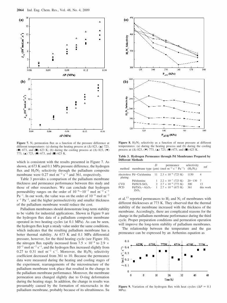
which is consistent with the results presented in Figure 7. Asshown, at 673 K and 0.1 MPa pressure difference, the hydrogenflux and H2/N2 selectivity through the palladium compositemembrane were 0.27 mol m-2 s-1 and 361, respectively.
Table 3 provides a comparison of the palladium membranethickness and permeance performance between this study andthose of other researchers. We can conclude that hydrogenpermeability ranges on the order of 10-6-10-7 mol m-2 s-1
Pa-1. In our work, the value was on the order of 10-6 mol m-2
s-1 Pa-1, and the higher permselectivity and smaller thicknessof the palladium membrane would reduce the cost.
Palladium membranes should demonstrate long-term stabilityto be viable for industrial applications. Shown in Figure 9 arethe hydrogen flux data of a palladium composite membraneoperated in two heating cycles (at 0.1 MPa). As can be seen,the hydrogen flux kept a steady value under the same conditions,which indicates that the resulting palladium membrane has abetter thermal stability. At 673 K and 0.1 MPa differentialpressure, however, for the third heating cycle (see Figure 10),the nitrogen flux rapidly increased from 7.5 × 10⁻⁴ to 2.9 ×10⁻² mol m-2 s-1, and the hydrogen flux increased slightly from0.27 to 0.31 mol m-2 s-1. Moreover, the H2/N2 selectivitycoefficient decreased from 361 to 10. Because the permeancedata were measured during the heating and cooling stages ofthe experiment, rearrangements of the microstructure of thepalladium membrane took place that resulted in the change inthe palladium membrane performance. Moreover, the membranepermeation area changed slightly due to O-ring deformationduring the heating stage. In addition, the change in results waspresumably caused by the formation of microcracks in thepalladium membrane, probably because of its ultrathinness. Su
et al.13 reported permeances to H2 and N2 of membranes withdifferent thicknesses at 773 K. They observed that the thermalstability of the membrane increased with the thickness of themembrane. Accordingly, there are complicated reasons for thechange in the palladium membrane performance during the thirdcycle. Proper preparation conditions and permeation operationwill improve the long-term stability of palladium membranes.
The relationship between the temperature and the gaspremeance can be expressed by an Arrhenius equation as
Figure 7. N2 permeation flux as a function of the pressure difference atdifferent temperatures: (a) during the heating process at (∆) 823, (2) 723,(b) 673, and (9) 623 K; (b) during the cooling process at (∆) 823, (1)773, (2) 723, (b) 673, and (9) 623 K.
Figure 8. H2/N2 selectivity as a function of mean pressure at differenttemperatures: (a) during the heating process and (b) during the coolingprocess at (∆) 823, (1) 773, (2) 723, (b) 673, and (9) 623 K.
Table 3. Hydrogen Permeance through Pd Membranes Prepared byDifferent Methods
method membrane typeD
(µm)permeance
(mol m-2 s-1 Pa-1)selectivity
(H2/N2)ref
electrolessplating
Pd-Cu/alumina 11 2.3 × 10⁻⁶ (723 K) 1150 4
Pd/alumina 1 2.2 × 10⁻⁷ (723 K) 20-130 7CVD Pd/SUS-SiO2 2 2.7 × 10⁻⁶ (773 K) 300 13PCD Pd/TiO2-Al2O3-
ZrO2-
1 2.7 × 10⁻⁶ (673 K) 361 this work
Figure 9. Variation of the hydrogen flux with heat cycles (∆P ) 0.1MPa).
2064 Ind. Eng. Chem. Res., Vol. 48, No. 4, 2009

F)F0 exp(-Ea/RT ) (4)
where F0 is the pre-exponential factor and Ea is the apparentactivation energy.
Figure 11 shows the Arrhenius relation between the rate ofhydrogen permeance and the temperature. The average activationenergy of the resulting palladium composite membrane wascalculated to be 17 KJ/mol in the temperature range of 623-823K, which includes the energy barriers for dissolution anddiffusion of hydrogen in the palladium layer and hydrogenpermeation in the porous support. As shown, a thinner metallicfilm would result in a relatively higher activation energy value,indicating that hydrogen transport in submicron-thick palladiummembranes is dominated by surface phenomena such asadsorption of H2 on metallic surfaces and dissociation to atomichydrogen.
According to eqs 1 and 4 and Figure 11, the permeationequation of the resulting palladium membrane in the temperaturerange of 623-823 K is given by
J) 4.88 × 10⁻⁵ exp(-2.045T )(Ph
0.8 -Pl0.8)
4. Conclusions
An improved electroless plating method was proposed to producepalladium composite membranes. A new activation technique byphotocatalytic deposition (PCD) of palladium was presented thatis attractive for its avoidance of codeposited impurities on thesurface of the resulting composite membrane. The thickness of thepalladium composite membrane was 1 µm. The hydrogen flux andselectivity through the palladium composite membrane were 0.27mol m-2 s-1 and 361, respectively, at 673 K and 0.1 MPadifferential pressure. Hydrogen flux data of the palladium compositemembrane indicated steady operation during two thermal cycles.The average activation energy of this ultrathin membrane forhydrogen permeation was 17 kJ/mol, and the n value wasapproximately 0.8 under all experimental conditions tested. Thehydrogen permeation performance diverged from Sievert’s law.The permeation equation of the resulting palladium membrane inthe temperature range of 623-823 K is given by J ) 4.88 ×10⁻⁵ exp(-2.045/T)(Ph
0.8 - Pl0.8).
Literature Cited
(1) Paglieri, J. D.; Way, J. D. Innovations in palladium membraneresearch. Sep. Purif. methods 2002, 31, 1.
(2) Huang, I.; Chen, C. S.; He, Z. D. Pd membranes supported on porousceramics prepared by chemical vapor deposition. Thin Solid Films 1997,302, 98.
(3) Brault, P.; Thomann, A. L.; Vignolle, C. A. Percolative growth ofPd ultrathin films deposited by plasma sputtering. Surf. Sci. 1998, 406, 597.
(4) Roa, F.; Way, D.; McCormick, R.; Paglieri, S. Preparation andcharacterization of Pd-Cu composite membranes for hydrogen separation.Chem. Eng. J. 2003, 93, 11.
(5) Nam, S. E.; Lee, S. H.; Lee, K. H. Preparation of a Pd alloycomposite membrane supported in a porous stainless steel by vacuumelectrodeposition. J. Membr. Sci. 2001, 15, 163.
(6) Paglieri, S. N.; Way, J. D. A new preparation technique for Pd/alumina membranes with enhanced high-temperature stability. Ind. Eng.Chem. Res. 1999, 38, 1925.
(7) Zhao, H. B.; Pflanz, J. H.; Gu, A. W.; Li, N. Preparation of palladiumcomposite membranes by modified electroless plating procedure. J. Membr.Sci. 1998, 14, 147.
(8) Li, X.; Fan, Y. Q.; Jin, W. Q.; Xu, N. P. Improved photocatalyticdeposition of palladium membranes. J. Membr. Sci. 2006, 282, 1.
(9) Ding, X. B.; Fan, Y. Q.; Xu, N. P. A new route for the fabricationof TiO2 ultrafiltration membranes with suspension derived from a wetchemical synthesis. J. Membr. Sci. 2006, 270, 179.
(10) Huang, Y.; Li, X.; Fan, Y. Q.; Xu, N. P. Progress in palladium-based composite membranes: Principle, preparation and characterization.Prog. Chem. 2006, 18, 230.
(11) Tuchlenski, A.; Uchytil, P.; Morgenstern, A. S. An experimentalstudy of combined gas phase and surface diffusion in porous glass. J.Membr. Sci. 1998, 140, 165.
(12) Xomeritakis, G.; Lin, Y. S. CVD synthesis and gas permeationproperties of thin palladium/alumina membranes. AIChE J. 1998, 1, 174.
(13) Su, C. L.; Jin, T.; Kuraoka, K. J. Thin palladium film supportedon SiO2-modified porous stainless steel for a high-hydrogen-flux membrane.Ind. Eng. Chem. Res. 2005, 44, 3053.
ReceiVed for reView March 22, 2008ReVised manuscript receiVed October 29, 2008
Accepted November 13, 2008
IE8004644
Figure 10. Comparison of three heating cycles (∆P ) 0.1 MPa, T )673 K).
Figure 11. Arrhenius plot of hydrogen permeability through the membrane(∆P ) 0.05 MPa).
Ind. Eng. Chem. Res., Vol. 48, No. 4, 2009 2065