prefabrication of tunnel elements the...
TRANSCRIPT
I
PREFABRICATION OF TUNNEL ELEMENTS The Development and Design of the Casting Yard
Rodolfo SPRENG, DUMEZ-GTM, 57 avenue Jules-Quentin, F-92022 Nanterre Cedex, France Robert BITTNER, BEN C. GERWICK INC., 601 Montgomery St., Suite 400, San Francisco, CA 94111 USA
Patrick GERNIGON, André PIQUET, DUMEZ-GTM, 57 avenue Jules-Quentin, F-92022 Nanterre Cedex Speaker Spreng Rodolfo Rodolfo Spreng has graduated in 1969 as civil engineer at the University of Stuttgart / Germany. He joined the engineering department of DUMEZ-GTM in 1989 and was assigned in 1995 to the Øresund Tunnel Joint Venture for the tender phase in Malmöe. As leader of the tunnel casting yard design team, he developed the base concepts and construction methods for the prefabrication scheme.
DUMEZ-GTM, 57 avenue Jules -Quentin, 92022 Nanterre Cedex, France Tel +33 1 41 91 46 63, Fax +33 1 41 91 45 30 e-mail : [email protected] Co-author Bittner Robert Robert Bittner is a graduate of Stanford University with B.S. and M.S. degrees in civil engineering. He represented Morrison Knudsen Corp. on the Øresund Tunnel Contractors Joint Venture (OTV-JV). He was the Bid Manager for the OTC -JV and after contract award was the Engineering Manager for the OTC-JV during the detail design of the tunnel and casting yard. He is currently Chief Engineer with Ben C. Gerwick, Inc.
BEN C. GERWICK INC. 601 Montgomery St., Suite 400 San Francisco, CA 94111, USA Tel +1 415 398 8972, Fax +1 415 433 8189 e-mail : [email protected]
Abstract The Øresund Tunnel at tender stage, presented a formidable challenge to the joint venture companies tendering for the project. It was to be the largest immersed tube tunnel ever built. It was to be built in a very sensitive environment, under severe climatic conditions and to very rigorous design and construction requirements. The tender submitted by Øresund Tunnel Contractors for design and construction of the Øresund Tunnel met this challenge by proposing the use of an innovative system for casting and launching of the tunnel elements. The two key concepts that made up this system were incremental match casting of full tunnel cross sections and the launching of the completed tunnel elements from a two level casting basin. The success of this cast and launch system depended on the development of the various construction methods proposed at tender, and how well those methods conformed to the tunnel design. This paper describes the development and evolution of these methods from the end of the tender stage to actual implementation. Keywords Øresund Tunnel Immersed Tunnel Pre-casting yard Incremental launching Sliding gate Floating gate
II
Co-author Gernigon Patrick Patrick Gernigon graduated at the ESPT Paris as civil engineer in 1972 with a specialisation of reinforced concrete and prestessed structures at the CHEBAP Institute of PARIS. Since 1974, when he joined the GTM Group, he was involved in the design of numerous large civil work projects and in particular he was in charge for ØTC–JV of the sliding gate and foundations design.
DUMEZ-GTM, 57 avenue Jules -Quentin, 92022 Nanterre Cedex, France Tel +33 1 41 91 43 79, Fax +33 1 41 91 40 60 e-mail : [email protected] Co-author Piquet André Certified European Engineer (EUR-ING 1994) André Piquet joined the GTM Group in 1979 after graduating at the University of Lille as Soil Techniques and Civil engineer. He works at DUMEZ-GTM’s Structural Design Department (BES) and as an expert on off-shore structures, the Øresund Joint Venture, entrusted him the design of the floating gate.
DUMEZ-GTM, 57 avenue Jules -Quentin, 92022 Nanterre Cedex, France Tel +33 1 41 91 45 29, Fax +33 1 41 91 40 60 e-mail : [email protected]
III
Introduction From the very beginning of the tender process, it was clear to the Øresund Tunnel Contractor’s design/build team that the Øresund Tunnel would be a unique and particularly challenging project. It would be not only the largest immersed tube tunnel ever built, but it would also have to be built to very rigid standards of quality, in a highly sensitive environment, under challenging climatic conditions and to a tight construction schedule. This challenge was first addressed during the tender stage when the contractor’s team of construction and design engineers developed the initial design of the tunnel and conceived the initial concepts for incremental casting and launching of the tunnel elements. These concepts and preliminary designs envisioned the use of a fully enclosed assembly line production process capable of producing a 55,000-ton tunnel element every month for 20 months. The entire process was built around two principal concepts: 1) Incremental match casting of full tunnel
sections in a fixed casting bed (a concept successfully used in bridge construction for over 30 years) and
2) A two level cast and launch basin that works similar to a navigation lock on a ship canal.
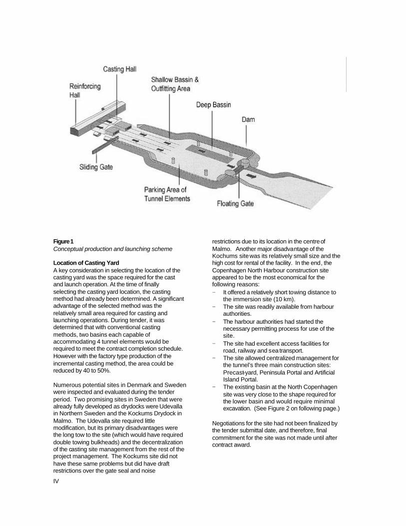
Both of these concepts had been successfully used in the past. However, they had not been applied to immersed tube tunnel construction. The application of these technologies to a new field, and the tailoring of the concepts to the Øresund Tunnel required solving a number of technical problems. By end of the tendering period, most of the technical problems had been identified and enough engineering had been performed to confirm that the entire system was workable, but the actual development of the various systems and methods to make the process a reality was performed after contact award. The focus of this paper is to describe the development and evolution of these methods from the completion of the tender stage to actual implementation. The intent of this paper is to describe the methods and to explain why the methods were selected. The Cast and Launch Method The general concepts for the casting and launching of the tunnel elements were developed during the tender stage. (See Figure 1 on following page.)
These concepts envisioned match casting, above sea level, complete tunnel sections 22-m in length on a fixed casting bed inside an enclosed facility protected from the weather. The reinforcing for these sections would be pre-assembled into complete cages within the building and slid into the forms as a single unit. The tunnel’s interior forms would telescope into the cage and the entire tunnel segment would be cast in a continuous placement of over 2700-m3. After curing for 48 hours, the forms would be stripped and the segment would be pushed clear of the casting bed, allowing the bed to be set up to receive the reinforcing cage for the next segment. This process would be completed eight times until a 175.5 m tunnel element had been completed. At this point the entire tunnel element would be pushed to an outfitting position above sea level where it would be completed and made ready for launch. The entire operation would be conducted on a continuous basis with each casting line producing a completed tunnel segment every week, while the outfitting of the completed tunnel elements took place independent from the casting operation. The launch method envisioned at tender time required a two level basin with upper end of the basin located 1-m above sea level, and the lower end of the basin at 10-m below sea level. The entire launch basin would be surrounded by an earthen berm with a sliding entrance gate at one end and a floating exit gate at the other end. The berm and gates would allow flooding of the entire basin to an elevation 10-m above sea level, and the floating of the completed tunnel element over the deeper end of the basin. The basin would then be drained back to sea level, and the tunnel element would be left floating at sea level. The floating exit gate would be removed from the end of the basin, and the tunnel would exit the basin for transport to the installation site and final immersion on the tunnel alignment. In order to meet the production requirement of one tunnel element per month, it was decided at tender time to construct two separate and independent production lines, each set up with its own casting bed, skid system and outfitting station. The following sections describe the development and implementation of these initial concepts after contract award.
IV
Figure 1 Conceptual production and launching scheme Location of Casting Yard A key consideration in selecting the location of the casting yard was the space required for the cast and launch operation. At the time of finally selecting the casting yard location, the casting method had already been determined. A significant advantage of the selected method was the relatively small area required for casting and launching operations. During tender, it was determined that with conventional casting methods, two basins each capable of accommodating 4 tunnel elements would be required to meet the contract completion schedule. However with the factory type production of the incremental casting method, the area could be reduced by 40 to 50%. Numerous potential sites in Denmark and Sweden were inspected and evaluated during the tender period. Two promising sites in Sweden that were already fully developed as drydocks were Udevalla in Northern Sweden and the Kockums Drydock in Malmo. The Udevalla site required little modification, but its primary disadvantages were the long tow to the site (which would have required double towing bulkheads) and the decentralization of the casting site management from the rest of the project management. The Kockums site did not have these same problems but did have draft restrictions over the gate seal and noise
restrictions due to its location in the centre of Malmo. Another major disadvantage of the Kochums site was its relatively small size and the high cost for rental of the facility. In the end, the Copenhagen North Harbour construction site appeared to be the most economical for the following reasons: − It offered a relatively short towing distance to
the immersion site (10 km). − The site was readily available from harbour
authorities. − The harbour authorities had started the
necessary permitting process for use of the site.
− The site had excellent access facilities for road, railway and sea transport.
− The site allowed centralized management for the tunnel’s three main construction sites: Precast-yard, Peninsula Portal and Artificial Island Portal.
− The existing basin at the North Copenhagen site was very close to the shape required for the lower basin and would require minimal excavation. (See Figure 2 on following page.)
Negotiations for the site had not been finalized by the tender submittal date, and therefore, final commitment for the site was not made until after contract award.
V
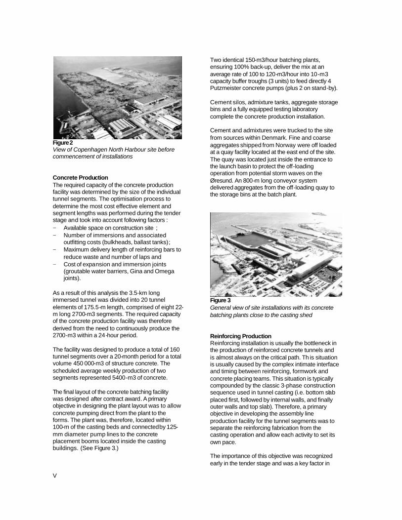
Figure 2 View of Copenhagen North Harbour site before commencement of installations Concrete Production The required capacity of the concrete production facility was determined by the size of the individual tunnel segments. The optimisation process to determine the most cost effective element and segment lengths was performed during the tender stage and took into account following factors : − Available space on construction site ; − Number of immersions and associated
outfitting costs (bulkheads, ballast tanks) ; − Maximum delivery length of reinforcing bars to
reduce waste and number of laps and − Cost of expansion and immersion joints
(groutable water barriers, Gina and Omega joints).
As a result of this analysis the 3.5-km long immersed tunnel was divided into 20 tunnel elements of 175.5-m length, comprised of eight 22-m long 2700-m3 segments. The required capacity of the concrete production facility was therefore derived from the need to continuously produce the 2700-m3 within a 24-hour period. The facility was designed to produce a total of 160 tunnel segments over a 20-month period for a total volume 450 000-m3 of structure concrete. The scheduled average weekly production of two segments represented 5400-m3 of concrete. The final layout of the concrete batching facility was designed after contract award. A primary objective in designing the plant layout was to allow concrete pumping direct from the plant to the forms. The plant was, therefore, located within 100-m of the casting beds and connected by 125-mm diameter pump lines to the concrete placement booms located inside the casting buildings. (See Figure 3.)
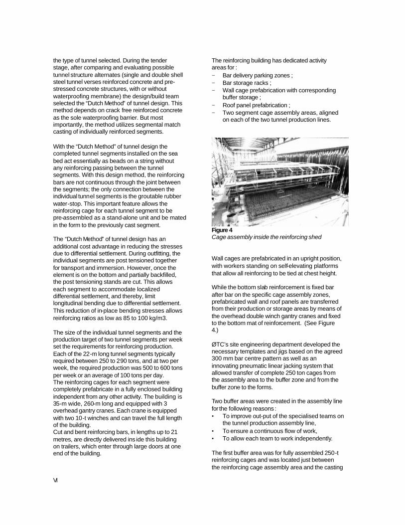
Two identical 150-m3/hour batching plants, ensuring 100% back-up, deliver the mix at an average rate of 100 to 120-m3/hour into 10-m3 capacity buffer troughs (3 units) to feed directly 4 Putzmeister concrete pumps (plus 2 on stand-by). Cement silos, admixture tanks, aggregate storage bins and a fully equipped testing laboratory complete the concrete production installation. Cement and admixtures were trucked to the site from sources within Denmark. Fine and coarse aggregates shipped from Norway were off loaded at a quay facility located at the east end of the site. The quay was located just inside the entrance to the launch basin to protect the off-loading operation from potential storm waves on the Øresund. An 800-m long conveyor system delivered aggregates from the off-loading quay to the storage bins at the batch plant.
Figure 3 General view of site installations with its concrete batching plants close to the casting shed Reinforcing Production Reinforcing installation is usually the bottleneck in the production of reinforced concrete tunnels and is almost always on the critical path. Th is situation is usually caused by the complex intimate interface and timing between reinforcing, formwork and concrete placing teams. This situation is typically compounded by the classic 3-phase construction sequence used in tunnel casting (i.e. bottom slab placed first, followed by internal walls, and finally outer walls and top slab). Therefore, a primary objective in developing the assembly line production facility for the tunnel segments was to separate the reinforcing fabrication from the casting operation and allow each activity to set its own pace. The importance of this objective was recognized early in the tender stage and was a key factor in
VI
the type of tunnel selected. During the tender stage, after comparing and evaluating possible tunnel structure alternates (single and double shell steel tunnel verses reinforced concrete and pre-stressed concrete structures, with or without waterproofing membrane) the design/build team selected the “Dutch Method” of tunnel design. This method depends on crack free reinforced concrete as the sole waterproofing barrier. But most importantly, the method utilizes segmental match casting of individually reinforced segments. With the “Dutch Method” of tunnel design the completed tunnel segments installed on the sea bed act essentially as beads on a string without any reinforcing passing between the tunnel segments. With this design method, the reinforcing bars are not continuous through the joint between the segments; the only connection between the individual tunnel segments is the groutable rubber water-stop. This important feature allows the reinforcing cage for each tunnel segment to be pre-assembled as a stand-alone unit and be mated in the form to the previously cast segment. The “Dutch Method” of tunnel design has an additional cost advantage in reducing the stresses due to differential settlement. During outfitting, the individual segments are post tensioned together for transport and immersion. However, once the element is on the bottom and partially backfilled, the post tensioning stands are cut. This allows each segment to accommodate localized differential settlement, and thereby, limit longitudinal bending due to differential settlement. This reduction of in-place bending stresses allows reinforcing ratios as low as 85 to 100 kg/m3. The size of the individual tunnel segments and the production target of two tunnel segments per week set the requirements for reinforcing production. Each of the 22-m long tunnel segments typically required between 250 to 290 tons, and at two per week, the required production was 500 to 600 tons per week or an average of 100 tons per day. The reinforcing cages for each segment were completely prefabricate in a fully enclosed building independent from any other activity. The building is 35-m wide, 260-m long and equipped with 3 overhead gantry cranes. Each crane is equipped with two 10-t winches and can travel the full length of the building. Cut and bent reinforcing bars, in lengths up to 21 metres, are directly delivered ins ide this building on trailers, which enter through large doors at one end of the building.
The reinforcing building has dedicated activity areas for : − Bar delivery parking zones ; − Bar storage racks ; − Wall cage prefabrication with corresponding
buffer storage ; − Roof panel prefabrication ; − Two segment cage assembly areas, aligned
on each of the two tunnel production lines.
Figure 4 Cage assembly inside the reinforcing shed Wall cages are prefabricated in an upright position, with workers standing on self-elevating platforms that allow all reinforcing to be tied at chest height. While the bottom slab reinforcement is fixed bar after bar on the specific cage assembly zones, prefabricated wall and roof panels are transferred from their production or storage areas by means of the overhead double winch gantry cranes and fixed to the bottom mat of reinforcement. (See Figure 4.) ØTC’s site engineering department developed the necessary templates and jigs based on the agreed 300 mm bar centre pattern as well as an innovating pneumatic linear jacking system that allowed transfer of complete 250 ton cages from the assembly area to the buffer zone and from the buffer zone to the forms. Two buffer areas were created in the assembly line for the following reasons : • To improve out-put of the specialised teams on
the tunnel production assembly line, • To ensure a continuous flow of work, • To allow each team to work independently. The first buffer area was for fully assembled 250-t reinforcing cages and was located just between the reinforcing cage assembly area and the casting

VII
beds. (See Figure 5.) The second buffer area was for completed tunnel segments and was located between the casting beds and upper end of the launch basin. The purpose of the second buffer was to separate the casting operation from the outfitting operation and to allow the continuous casting while outfitting and launching of the completed tunnel elements. The second buffer was designed for a capacity of four casting cycles or one month at standard production.
Figure 5 Completed 250 ton cages in buffer area waiting to be skidded into the casting cell Forming System Full section casting offered significant advantages over conventional tunnel casting techniques: − It met the need for assembly line production by
providing a single stage casting operation that could be completed in a relatively short time.
− It significantly reduced thermal stresses in the tunnel cross-section by allowing the entire tunnel section to expand and contract at the same rate, and thereby, offered the potential for complete elimination of artificial cooling systems.
− It eliminated all longitudinal construction joints in the tunnel, and thereby, helped ensure the water tightness of the tunnel.
During the initial planning stages for the project, the advantages of assembly line production and full section casting were established as end objectives, but the construction methods for actually casting a full tunnel section at one time had not been fully developed. The tender team was aware of a project in Germany where PERI, the form design and supply firm, had designed and built a telescoping form system for full section casting of 10-m tunnel sections on a cut-and-cover metro tunnel leading to the new Munich airport. On this Munich project, the tunnel segments were cast in-situ, and the form travelled longitudinally for
match casting of the next tunnel segment. After further investigation, it was determined that the system could be modified to accommodate a fixed casting bed with pre-assembled reinforcing cages being fed into one end and tunnel segments being pushed out the other end. (As a side note, research on this same Munich project by Prof. Dr. Ivani of the University of Bochum was extremely useful in confirming the reduction of thermal stresses with full section casting.) The form system developed for the Øresund Tunnel casting scheme is a hydraulically operated steel form designed for continuous casting of 22-m long 2700 m3 segments. The form system for each casting bed consists of 5 basic elements : − Five collapsible bottom slab forms located in
fixed position between the skid beams ; − Two external wall outer panels that can retract
from the completed casting ; − Five internal tunnel forms (2 railway bores, 2
road bores and 1 escape way bore) ; − Five corresponding tunnel form launching
girders (trusses) ; and − Two stop-end shutters (only one is required for
segments 2 to 8).
Figure 6 PERI steel form cells being assembled in the casting shed The forming of a tunnel segment begins with the sliding of a fully assembled reinforcing cage on to the pre-set bottom forms. The 5 launch girders (designed as steel trusses) are then telescoped into the interior of the five bores of the pre-assembled reinforcing cage. (See Figure 7.) Support legs positioned on the end of the telescoping truss are then landed outside the end of the cage, and the interior forms are slid along the truss into the interior of the tunnel’s five bores. Once the interior forms are in the correct longitudinal position, they are expanded outward and locked in position for casting. The exterior side
VIII
forms and end bulkheads are then positioned and the form is ready to receive concrete.
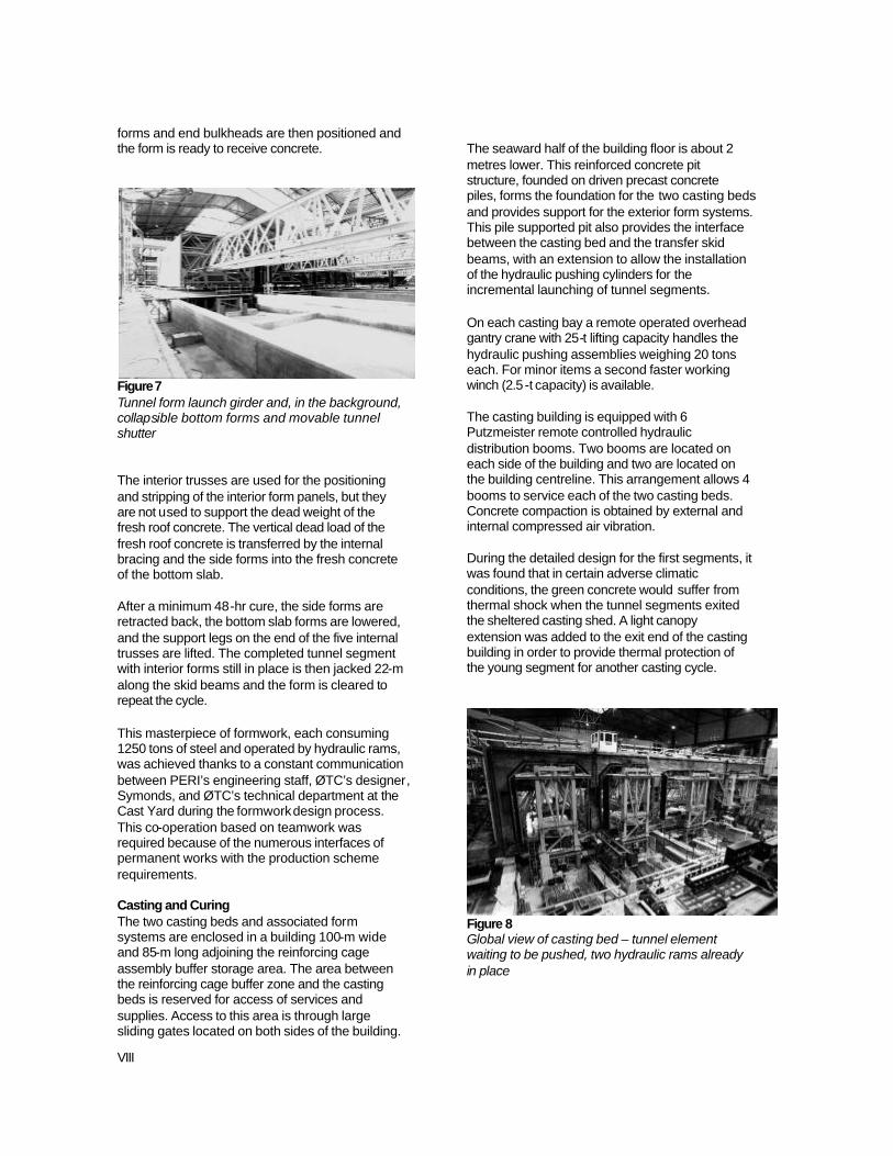
Figure 7 Tunnel form launch girder and, in the background, collapsible bottom forms and movable tunnel shutter The interior trusses are used for the positioning and stripping of the interior form panels, but they are not used to support the dead weight of the fresh roof concrete. The vertical dead load of the fresh roof concrete is transferred by the internal bracing and the side forms into the fresh concrete of the bottom slab. After a minimum 48-hr cure, the side forms are retracted back, the bottom slab forms are lowered, and the support legs on the end of the five internal trusses are lifted. The completed tunnel segment with interior forms still in place is then jacked 22-m along the skid beams and the form is cleared to repeat the cycle. This masterpiece of formwork, each consuming 1250 tons of steel and operated by hydraulic rams, was achieved thanks to a constant communication between PERI’s engineering staff, ØTC’s designer, Symonds, and ØTC’s technical department at the Cast Yard during the formwork design process. This co-operation based on teamwork was required because of the numerous interfaces of permanent works with the production scheme requirements. Casting and Curing The two casting beds and associated form systems are enclosed in a building 100-m wide and 85-m long adjoining the reinforcing cage assembly buffer storage area. The area between the reinforcing cage buffer zone and the casting beds is reserved for access of services and supplies. Access to this area is through large sliding gates located on both sides of the building.
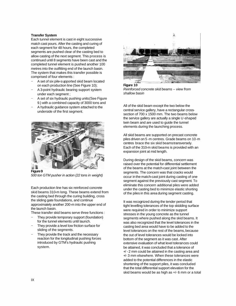
The seaward half of the building floor is about 2 metres lower. This reinforced concrete pit structure, founded on driven precast concrete piles, forms the foundation for the two casting beds and provides support for the exterior form systems. This pile supported pit also provides the interface between the casting bed and the transfer skid beams, with an extension to allow the installation of the hydraulic pushing cylinders for the incremental launching of tunnel segments. On each casting bay a remote operated overhead gantry crane with 25-t lifting capacity handles the hydraulic pushing assemblies weighing 20 tons each. For minor items a second faster working winch (2.5 -t capacity) is available. The casting building is equipped with 6 Putzmeister remote controlled hydraulic distribution booms. Two booms are located on each side of the building and two are located on the building centreline. This arrangement allows 4 booms to service each of the two casting beds. Concrete compaction is obtained by external and internal compressed air vibration. During the detailed design for the first segments, it was found that in certain adverse climatic conditions, the green concrete would suffer from thermal shock when the tunnel segments exited the sheltered casting shed. A light canopy extension was added to the exit end of the casting building in order to provide thermal protection of the young segment for another casting cycle.
Figure 8 Global view of casting bed – tunnel element waiting to be pushed, two hydraulic rams already in place
IX
Transfer System Each tunnel element is cast in eight successive match cast pours. After the casting and curing of each segment for 48 hours, the completed segments are pushed clear of the casting bed to allow casting of the next segment. This process is continued until 8 segments have been cast and the completed tunnel element is pushed another 100 metres into the outfitting end of the launch basin. The system that makes this transfer possible is comprised of four elements : − A set of six pile-supported skid beam located
on each production line (See Figure 10); − A 3-point hydraulic bearing support system
under each segment ; − A set of six hydraulic pushing units (See Figure
9.) with a combined capacity of 3000 tons and − A hydraulic guidance system attached to the
underside of the first segment.
Figure 9 500 ton GTM pusher in action (22 tons in weight) Each production line has six reinforced concrete skid beams 310-m long. These beams extend from the casting bed through the curing building, cross the sliding gate foundations, and continue approximately another 200-m into the upper end of the launch basin. These transfer skid beams serve three functions : − They provide temporary support (foundation)
for the tunnel elements until launch. − They provide a level low friction surface for
sliding of the segments. − They provide the track and the necessary
reaction for the longitudinal pushing forces introduced by GTM’s hydraulic pushing system.
Figure 10 Reinforced concrete skid beams – view from shallow basin All of the skid beam except the two below the central service gallery, have a rectangular cross-section of 700 x 1500 mm. The two beams below the service gallery are actually a single U -shaped twin beam and are used to guide the tunnel elements during the launching process. All skid beams are supported on precast concrete piles driven on 5 -m centres. Grade beams on 10-m centres brace the six skid beams transversely. Each of the 310-m skid beams is provided with an expansion joint at mid length. During design of the skid beams, concern was raised over the potential for differential settlement of the beams at the match-cast joint between the segments. The concern was that cracks would occur in the match-cast joint during casting of one segment against the previously cast segment. To eliminate this concern additional piles were added under the casting bed to minimize elastic shorting of the piles in this area during segment casting. It was recognized during the tender period that tight levelling tolerances of the top skidding surface were required in order to minimize support stresses in the young concrete as the tunnel segments where pushed along the skid beams. It was also recognized that the level tolerances in the casting bed area would have to be added to the level tolerances on the rest of the beams, because the out of level tolerances would be locked into bottom of the segment as it was cast. After extensive evaluation of what level tolerances could be attained, it was concluded that a tolerance of +/ - 2 mm could be attained in the casting area and +/- 3 mm elsewhere. When these tolerances were added to the potential differences in the elastic shortening of the support piles, it was concluded that the total differential support elevation for the skid beams would be as high as +/- 6 mm or a total
X
potential difference of 12 mm between any two support beams. This information was fed into a finite element model of the tunnel segments, and the resulting analysis indicated a risk of cracking the freshly cast tunnel segments. The decision was, therefore, taken to provide hydraulic bearing supports between the underside of the tunnel segments and the top of the skid beams. The design team first evaluated the use of hydraulic flat jacks. However, after trial load tests with the flat jacks, it was found that cracking occurred in the thin steel plates of the jacks at the junction of the bulb with the outer edge of the flat circle area after about 30 cycles of 0 to 20 mm movement (at max. vertical load). It was, therefore, decided to develop low profile custom made hydraulic jacks with spherical heads and a capacity of 300 to 400-t. After striking bottom slab forms, the weight of each tunnel segment (approximately 7000 tons) is transferred to the skid beams via hydraulic jacks located at 3.65-m spacing along the top of the skid beam. A total of 36 bearings under each segment (for a total of 288 under a completed tunnel element) are put under design pressure by means of a hydraulic pump just before collapsing the bottom forms. The 36 bearings are connected into three circuits to provide an independent three-point support system for each segment. Each of the three hydraulic support systems is equipped with it’s own hydraulic accumulator to provide a well defined spring constant and even support of the tunnel element as it is pushed along the top of the skid beams. Initially stainless steel plates were bonded to the top of the beams and used as the sliding surface for the PTFE interface bonded to the bottom of the support bearings. During transfer of the initial tunnel segments, the epoxy bond between the top of the beam and the underside of the stainless steel plates started to fail. As a remedial action, it was decided to remove the stainless steel plates completely, and allow the PTFE pads to bear directly on the self-levelling epoxy compound, which proved to have a similar friction coefficient as the steel plates (3 to 4% at breakout and approximately 1% moving). Outfitting Station It was recognised at tender and proven during construction, that due to the compact nature of the casting yard, and the easy and short access distances into the tunnel bores, a significant portion of the internal tunnel outfitting could be
done cost effectively in the casting yard before launch of the elements. This work included : − Installation of pre-cast floor slabs in the escape
gallery; − Installation of fixing devices for the electric and
mechanical works; − Storage of pipes for mechanical works ; − Casting large part of the ballast concrete in the
railway bores. In addition to this work, the outfitting station was used to prepare the tunnel elements for transport and immersion. This work included: longitudinal post tension of the elements, installation of temporary ballast tanks, attachment of Gina seals, and installation of end bulkheads to allow floatation of the tunnel elements. Two Level Basin – Earthworks The launch basin (See Figure 11.) is enclosed by three different elements : − Along the north and south sides of the basin
there are 10.2-m high bunds (earth dams) ; − At the entrance end, a 100-m long sliding gate
opens towards the pre-casting factory ; and − At the exit end, a floating gate that opens to
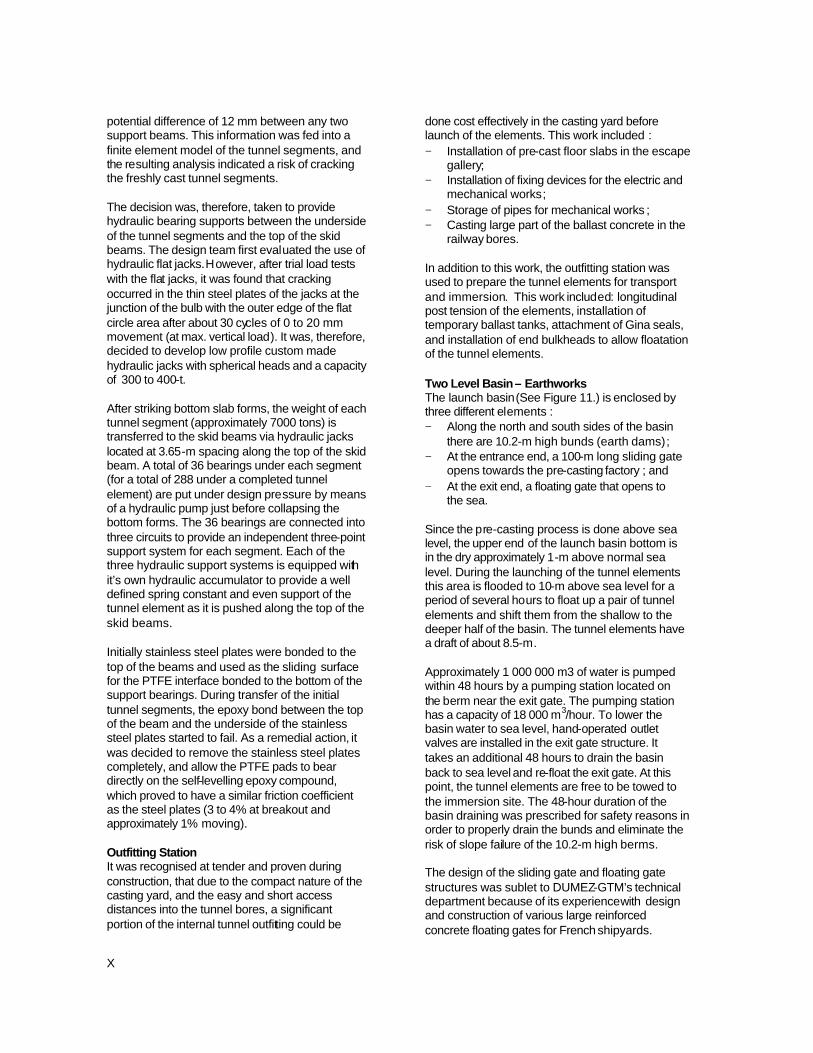
the sea. Since the pre-casting process is done above sea level, the upper end of the launch basin bottom is in the dry approximately 1-m above normal sea level. During the launching of the tunnel elements this area is flooded to 10-m above sea level for a period of several hours to float up a pair of tunnel elements and shift them from the shallow to the deeper half of the basin. The tunnel elements have a draft of about 8.5-m. Approximately 1 000 000 m3 of water is pumped within 48 hours by a pumping station located on the berm near the exit gate. The pumping station has a capacity of 18 000 m3/hour. To lower the basin water to sea level, hand-operated outlet valves are installed in the exit gate structure. It takes an additional 48 hours to drain the basin back to sea level and re-float the exit gate. At this point, the tunnel elements are free to be towed to the immersion site. The 48-hour duration of the basin draining was prescribed for safety reasons in order to properly drain the bunds and eliminate the risk of slope failure of the 10.2-m high berms. The design of the sliding gate and floating gate structures was sublet to DUMEZ-GTM’s technical department because of its experience with design and construction of various large reinforced concrete floating gates for French shipyards.
XI
Two 10.2-m high bunds along both sides of the launch basin are principally made with the excavated material from the deeper part of the basin. Before starting the excavation, a dike was built across the bay entrance, and a sheet-pile cut-off curtain was driven along the centreline of the dike and through a zone where a previous soil investigation had shown a permeable sandy soil layer. The sheets were terminated in the under lying limestone layer. The ground water table was then lowered by 12 deep wells with a pumping capacity limited (due to environmental restrictions) to 1500 m3/hour. A maximum pumping of 1200 m3/hour was finally needed to dry up the lower basin area and allow in-the-dry excavation of the lower basin down to 10-m below sea level. The dam fill was placed on a drainage layer and selected clayey material was carefully compacted in thin layers on the bund’s waterside to improve tightness and stability. Several piezometers placed at different locations monitored the water head when the basin was flooded. The sliding gate tied into the end of the bunds with a square sheet-pile cofferdam at the opening side and a sheet-pile retaining wall at the closing interface with the gate. On the seaward side, both berms terminate with vertical sheet-pile retaining walls (20 m free standing) with 4 anchor tie levels. Between these walls is located the floating exit gate. The deep section of the launch basin provided a perfectly sheltered storage basin for two tunnel elements before they are transferred to the immersion preparation area.
Figure 11 Two-level basin earth works and gates completed – temporary seaside dike is being dredged after successful test of gates
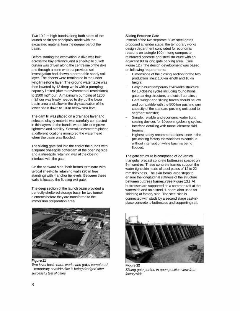
Sliding Entrance Gate Instead of the two separate 50-m steel gates proposed at tender stage, the temporary works design department concluded for economic reasons on a single 100-m long composite reinforced concrete and steel structure with an adjacent 100m long gate parking area. (See Figure 12.) The design development was based on following requirements: − Dimensions of the closing section for the two
production lines: 100-m length and 10-m height;
− Easy to build temporary civil works structure for 10 closing cycles including foundations, gate parking structure, and cut-off curtains ;
− Gate weight and sliding forces should be low and compatible with the 500-ton pushing ram capacity of the standard pushing unit used to segment transfer;
− Simple, reliable and economic water tight sealing devices for 10 opening/closing cycles;
− Interface detailing with tunnel element skid beams ;
− Highest safety recommendations since in the pre-casting factory the work has to continue without interruption while basin is being flooded.
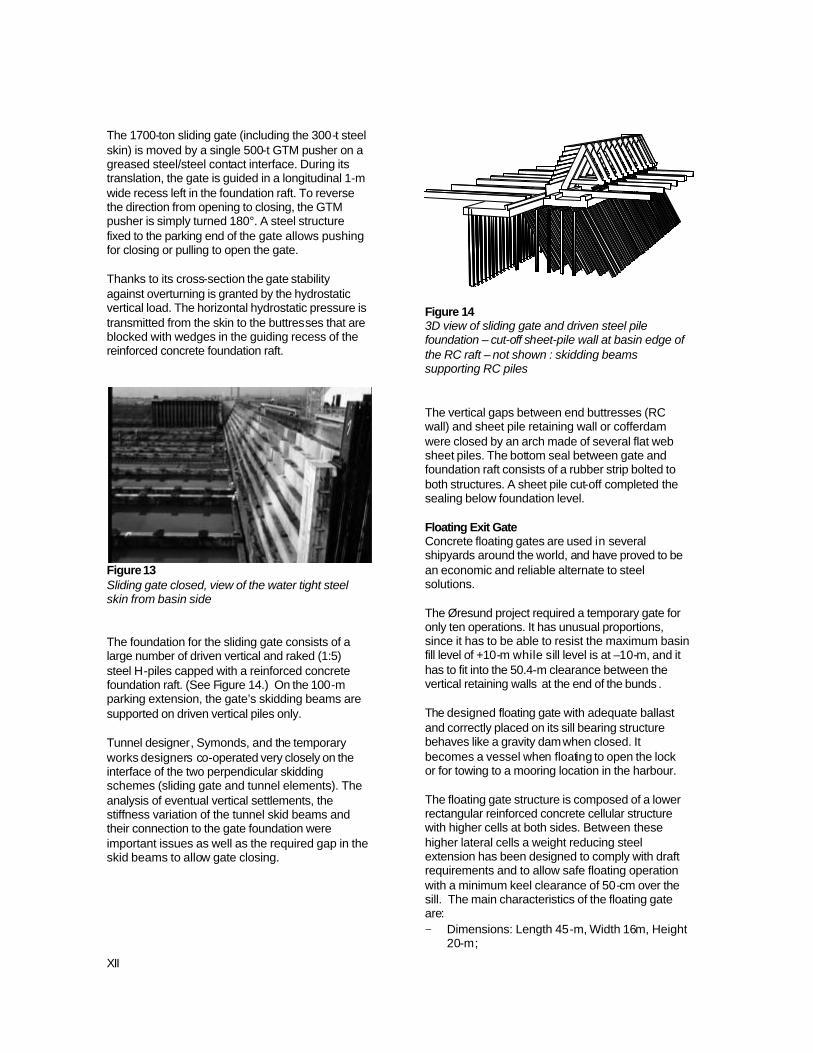
The gate structure is composed of 22 vertical triangular precast concrete buttresses spaced on 5-m centres. These concrete frames support the water tight skin made of steel plates of 12 to 22 mm thickness. The skin forms large steps to ensure the longitudinal stiffness of the structure between buttress frames. (See Figure 13.) All buttresses are supported on a common raft at the waterside and on a steel H-beam also used for skidding at factory side. The steel skin is connected with studs by a second stage cast-in- place concrete to buttresses and supporting raft.
Figure 12 Sliding gate parked in open position view from factory side
XII
The 1700-ton sliding gate (including the 300-t steel skin) is moved by a single 500-t GTM pusher on a greased steel/steel contact interface. During its translation, the gate is guided in a longitudinal 1-m wide recess left in the foundation raft. To reverse the direction from opening to closing, the GTM pusher is simply turned 180°. A steel structure fixed to the parking end of the gate allows pushing for closing or pulling to open the gate. Thanks to its cross-section the gate stability against overturning is granted by the hydrostatic vertical load. The horizontal hydrostatic pressure is transmitted from the skin to the buttresses that are blocked with wedges in the guiding recess of the reinforced concrete foundation raft.
Figure 13 Sliding gate closed, view of the water tight steel skin from basin side The foundation for the sliding gate consists of a large number of driven vertical and raked (1:5) steel H-piles capped with a reinforced concrete foundation raft. (See Figure 14.) On the 100-m parking extension, the gate’s skidding beams are supported on driven vertical piles only. Tunnel designer, Symonds, and the temporary works designers co-operated very closely on the interface of the two perpendicular skidding schemes (sliding gate and tunnel elements). The analysis of eventual vertical settlements, the stiffness variation of the tunnel skid beams and their connection to the gate foundation were important issues as well as the required gap in the skid beams to allow gate closing.
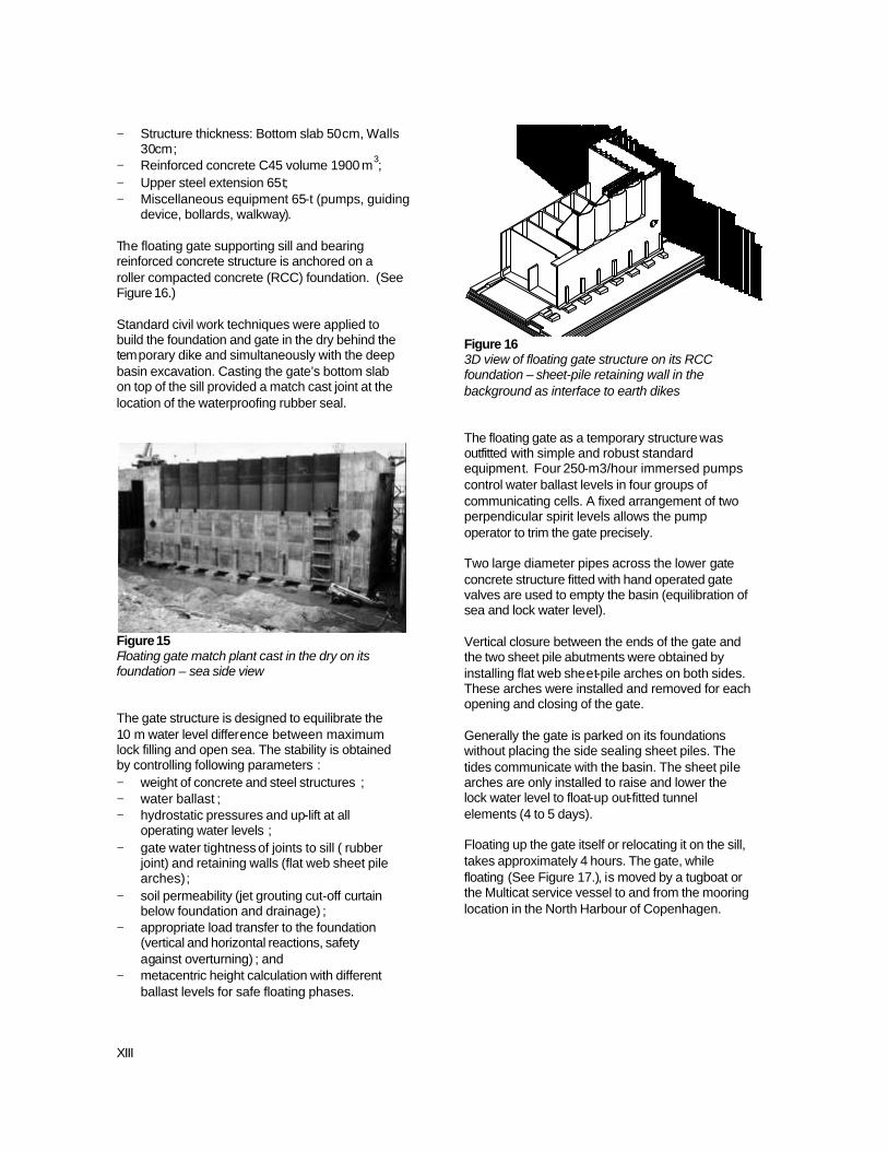
Figure 14 3D view of sliding gate and driven steel pile foundation – cut-off sheet-pile wall at basin edge of the RC raft – not shown : skidding beams supporting RC piles The vertical gaps between end buttresses (RC wall) and sheet pile retaining wall or cofferdam were closed by an arch made of several flat web sheet piles. The bottom seal between gate and foundation raft consists of a rubber strip bolted to both structures. A sheet pile cut-off completed the sealing below foundation level. Floating Exit Gate Concrete floating gates are used in several shipyards around the world, and have proved to be an economic and reliable alternate to steel solutions. The Øresund project required a temporary gate for only ten operations. It has unusual proportions, since it has to be able to resist the maximum basin fill level of +10-m while sill level is at –10-m, and it has to fit into the 50.4-m clearance between the vertical retaining walls at the end of the bunds . The designed floating gate with adequate ballast and correctly placed on its sill bearing structure behaves like a gravity dam when closed. It becomes a vessel when floating to open the lock or for towing to a mooring location in the harbour. The floating gate structure is composed of a lower rectangular reinforced concrete cellular structure with higher cells at both sides. Between these higher lateral cells a weight reducing steel extension has been designed to comply with draft requirements and to allow safe floating operation with a minimum keel clearance of 50-cm over the sill. The main characteristics of the floating gate are: − Dimensions: Length 45-m, Width 16m, Height
20-m;
XIII
− Structure thickness: Bottom slab 50cm, Walls 30cm;
− Reinforced concrete C45 volume 1900 m3; − Upper steel extension 65t; − Miscellaneous equipment 65-t (pumps, guiding
device, bollards, walkway). The floating gate supporting sill and bearing reinforced concrete structure is anchored on a roller compacted concrete (RCC) foundation. (See Figure 16.) Standard civil work techniques were applied to build the foundation and gate in the dry behind the temporary dike and simultaneously with the deep basin excavation. Casting the gate’s bottom slab on top of the sill provided a match cast joint at the location of the waterproofing rubber seal.
Figure 15 Floating gate match plant cast in the dry on its foundation – sea side view The gate structure is designed to equilibrate the 10 m water level difference between maximum lock filling and open sea. The stability is obtained by controlling following parameters : − weight of concrete and steel structures ; − water ballast ; − hydrostatic pressures and up-lift at all
operating water levels ; − gate water tightness of joints to sill ( rubber
joint) and retaining walls (flat web sheet pile arches) ;
− soil permeability (jet grouting cut-off curtain below foundation and drainage) ;
− appropriate load transfer to the foundation (vertical and horizontal reactions, safety against overturning) ; and
− metacentric height calculation with different ballast levels for safe floating phases.
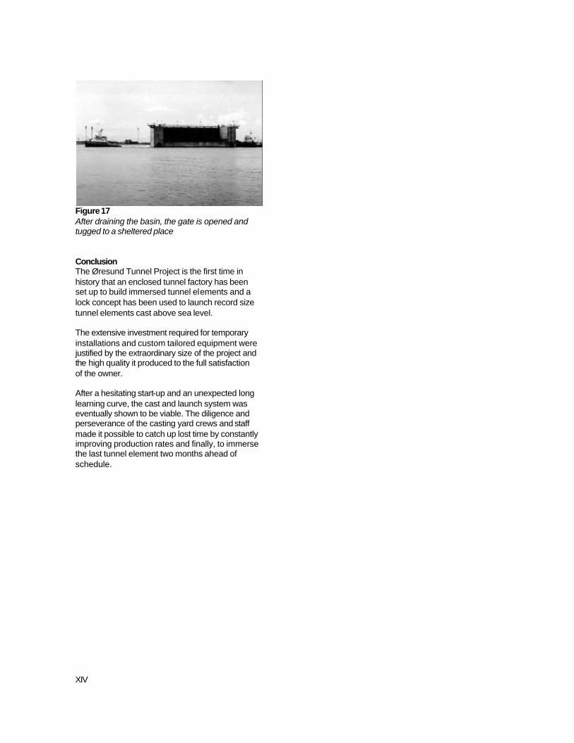
Figure 16 3D view of floating gate structure on its RCC foundation – sheet-pile retaining wall in the background as interface to earth dikes The floating gate as a temporary structure was outfitted with simple and robust standard equipment. Four 250-m3/hour immersed pumps control water ballast levels in four groups of communicating cells. A fixed arrangement of two perpendicular spirit levels allows the pump operator to trim the gate precisely. Two large diameter pipes across the lower gate concrete structure fitted with hand operated gate valves are used to empty the basin (equilibration of sea and lock water level). Vertical closure between the ends of the gate and the two sheet pile abutments were obtained by installing flat web sheet-pile arches on both sides. These arches were installed and removed for each opening and closing of the gate. Generally the gate is parked on its foundations without placing the side sealing sheet piles. The tides communicate with the basin. The sheet pile arches are only installed to raise and lower the lock water level to float-up out-fitted tunnel elements (4 to 5 days). Floating up the gate itself or relocating it on the sill, takes approximately 4 hours. The gate, while floating (See Figure 17.), is moved by a tugboat or the Multicat service vessel to and from the mooring location in the North Harbour of Copenhagen.
XIV
Figure 17 After draining the basin, the gate is opened and tugged to a sheltered place Conclusion The Øresund Tunnel Project is the first time in history that an enclosed tunnel factory has been set up to build immersed tunnel elements and a lock concept has been used to launch record size tunnel elements cast above sea level. The extensive investment required for temporary installations and custom tailored equipment were justified by the extraordinary size of the project and the high quality it produced to the full satisfaction of the owner. After a hesitating start-up and an unexpected long learning curve, the cast and launch system was eventually shown to be viable. The diligence and perseverance of the casting yard crews and staff made it possible to catch up lost time by constantly improving production rates and finally, to immerse the last tunnel element two months ahead of schedule.