prediction of thermal performance of multi pass cross flow...
TRANSCRIPT
Abstract—A steady state heat exchanger performance model
termed the matrix approach was previously developed by
Silaipillayarputhur and Idem to study the performance of multi-row
multi-pass cross flow tubular heat exchangers. This paper utilizes the
matrix approach to study the steady state sensible performance of
cross flow heat exchangers subjected to varying thermal and design
conditions. Parallel and counter cross flow heat exchangers have
been considered in this study. The cross flow heat exchanger's input
and the thermal performance are described through dimensionless
parameters. Since the heat exchanger's performance is observed at
each individual tube pass and since the performance is evaluated
through meaningful and industry recognized dimensionless input
parameters, this study shall benefit the heat exchanger designers in
designing an optimum and a cost efficient heat exchanger. The
“intermediate” thermal performance of cross flow heat exchangers
has not yet been described in the available literature.
Keywords—Steady state heat exchanger performance, Matrix
approach, Cross flow heat exchanger.
I. INTRODUCTION
ROSS flow heat exchangers are commonly employed for
several heating and cooling requirements in petrochemical
industries. They are also commonly used in precision and
comfort air conditioning applications. Understanding the
steady state sensible performance of a cross flow heat
exchanger is imperative during the design phase, as this shall
help the designers in choosing an optimum (size, material,
flow configuration, construction) and a cost efficient heat
exchanger.
Popularly used circuiting configurations such as parallel
cross flow and counter cross flow have been considered in this
study. The inputs to the heat exchanger are presented in terms
of meaningful parameters such as NTU, capacity rate ratio,
dimensionless fluid inlet temperatures. Reasonable range of
number of transfer units (NTU's), capacity rate ratios and
temperature ratio's commonly encountered in petrochemical
industries have been considered in this study. Since the
calculation of NTU encompasses size, design, material,
thermal and flow characteristics, this study can be used as a
guide during the heat exchanger design phase. The overall and
intermediate performances of parallel and counter cross flow
Karthik Silaipillayarputhur, Ph.D., Assistant Professor, Department of
Mechanical Engineering, King Faisal University, KSA. Contact:
+966504538025; +966-13-5898810. Email ID: [email protected];
heat exchangers have been clearly depicted for each
dimensionless input conditions. The “intermediate” thermal
performance of the heat exchanger has not yet been described
in the available literature.
Matrix approach previously developed by
Silaipillayarputhur and Idem [1] have been used in this study
to determine the performance of the heat exchanger. Matrix
approach is very flexible and can directly calculate the fluid
temperatures between the heat exchanger assemblies and
between the tube rows with an assembly without any additional
effort. Several studies have been reported in the literature on
the steady heat exchanger performance and only the topics that
are of relevance are reported herein.
Domingos [2] presented a general method of calculating the
total effectiveness and intermediate temperatures of assemblies
of heat exchangers. Domingos used the concept of
effectiveness and a local energy balance to predict the
performance of complex crossflow heat exchangers. Domingos
employed the static thermal transfer matrix and thermal
transfer factor to calculate the performance of an assembly of
heat exchangers. The assemblies consisted of associations of
heat exchangers of all types. This approach utilized a formal
matrix approach (taken from control theory) to relate the inlet
and outlet temperatures of the fluid streams. The intermediate
and final temperatures were not directly computed, but could
be computed with additional steps. The matrix approach has
some similarities to the Domingos method. Shah and Pignotti
[3] examined very complex heat exchanger flow arrangements
and related them to simple forms for which either a solution
existed or an approximate solution could be derived. Several
complex heat exchanger configurations were obtained for a
tube bundle comprised of six rows and 60 tubes. Chen and
Hsieh [4] presented a simple and a systematic procedure to
determine the effectiveness and exit temperatures of complex
assemblies of identical heat exchangers. Three different
assemblies were considered for overall parallel flow and
overall counter flow configurations. Navarro and Gomez [5, 6,
7] presented a new methodology for steady state cross-flow
heat exchanger thermal performance calculations. Their
approach was characterized by the division of the heat
exchanger into a number of small and simple one-pass “mixed-
unmixed” cross-flow heat exchangers, where the hot fluid was
mixed and the cold fluid was unmixed. The numerical model
was based on the tube element approach, according to which
the heat exchanger outlet temperatures were obtained by
Prediction of Thermal Performance of Multi
Pass Cross Flow Heat Exchangers
Karthik Silaipillayarputhur Ph.D.
C
International Conference on IT, Architecture and Mechanical Engineering (ICITAME'2015) May 22-23, 2015 Dubai (UAE)
http://dx.doi.org/10.15242/IIE.E0515010 36
discretizing the coil along the tube fluid path. In this model,
each element was composed of a small section of tube with its
fins. The size of the element was sufficiently small for the heat
capacity rate of the external fluid to be similarly small. In the
cross section of the element, the heat capacity rate ratio tended
to zero, and the tube side fluid temperature was assumed
constant, and was controlled by a local effectiveness. They
developed an algorithm for the determination of the thermal
effectiveness of cross-flow heat exchanger, and validated the
proposed methodology and results through comparison with
well-established analytical and theoretical results. This
methodology was suitable for predicting the performance of
cross-flow heat exchangers where analytical or approximate
solutions were not possible.
NOMENCLATURE
– Heat exchanger effectiveness
- Heat exchanger effectiveness per pass
n – Number of passes
NTU – Overall number of transfer units
NTU” – NTU per pass
r – Overall heat capacity rate ratio
r” – Capacity rate ratio per pass
AT - Temperature of the external fluid
AiT - Inlet temperature of the external fluid
AoT - Outlet temperature of the external fluid
AnT - Temperature of external fluid exiting pass “n” (described
in the tables)
BT - Temperature of the tube side fluid
BiT - Inlet temperature of the tube side fluid
BoT - Outlet temperature of the tube side fluid
BnT - Temperature of tube side fluid exiting pass “n” C
(described in the tables)
T - Dimensionless temperature
II. THERMAL PERFORMANCE OF THE CROSS FLOW HEAT
EXCHANGER
As stated previously, matrix approach was employed to
study the overall and the intermediate thermal performance of
parallel and counter cross flow heat exchangers. The external
fluid was considered as the “A” fluid and whereas the internal
or the tube side fluid was designated as the “B” fluid. In every
instance the tube side fluid was assumed to be the maximum
capacity rate fluid. The following are the assumptions used in
this study:
1. The fluid heat capacity rate ratio is a constant.
2. Both fluids are completely mixed at the inlet and
discharge of each heat exchanger assembly.
3. Fluid thermal property variations throughout the heat
exchanger are disregarded, and there is no phase change.
4. NTU is assumed to be uniformly distributed throughout
the heat exchanger.
5. There is negligible heat transfer between each row/pass
and its surroundings.
6. There are negligible potential and kinetic energy changes
in any given row/pass in the heat exchanger.
Per the matrix approach [1], for an overall counter flow,
multi-pass, one row per pass crossflow heat exchanger, the
generalized equations for solving the intermediate and final
temperatures of both fluids for a counter cross flow heat
exchanger are given as follows. If “m” corresponds to the
number of passes, “n” corresponds to twice the number of
passes, and j corresponds to anywhere between “1” and “n”,
then.
For j = 1
AirjBjrjjAj TTT 11, (1)
For j = 2;m-1
01 1,1,,1 jBjrjjAjjAjrj TTT (2)
For j = m
BirjAojAjrj TTT ,11 (3)
For j = m+1;n-2
02,11,2,11, mjmBjmjmBjmjmAjmjmAj TTTrTr
(4)
For j = n-1
BimjmBjmjmAjmjmAj TTTrTr 1,2,11, (5)
For j = n
AiBoBA TrTTTr 1212 (6)
Equations (1) through (6) can be readily employed to
determine the intermediate and final temperatures of both the
fluids in the given counter cross flow heat exchanger.
Likewise, for an overall parallel flow, multi-pass, one row
per pass crossflow heat exchanger, the generalized equations
for solving the intermediate and final temperatures of both
fluids for a parallel cross flow heat exchanger are given as
follows [1]. If “m” corresponds to the number of passes, “n”
corresponds to twice the number of passes, and j corresponds
to anywhere between “1” and “n”, then:
For j = 1
BiAijBjjAj TTrTTr 1,1, (7)
For j = 2;m-1
01,,11,,1 jBjjBjjAjjAj TTTrTr
(8)
For j = m
0,1,1 BojBjAojAj TTTrTr (9)
For j = m+1
BirAirA TTT 1112 1 (10)
For j = m+2;n-1
01 ,11,,1 mjmBjmrjmjmAjmjmAjmrj TTT (11)
For j = n
01 ,1,1 mjmBjmrjAomjmAjmrj TTT
(12)
Equations (7) through (12) can be readily employed to
determine the intermediate and final temperatures of both the
fluids for any number of passes in a given parallel cross flow
International Conference on IT, Architecture and Mechanical Engineering (ICITAME'2015) May 22-23, 2015 Dubai (UAE)
http://dx.doi.org/10.15242/IIE.E0515010 37
heat exchanger. Recognize that in this study “NTU” and
capacity rate ratio “r” are assumed to be input quantities. The
NTU of the heat exchanger is assumed to be divided equally
among the passes of the heat exchanger and thus NTU per pass
may be defined as
n
NTUUNT (13)
where n is the number of passes. Each pass of the heat
exchanger encounters full flow rate of the tube side and the
external fluid. Thus the capacity rate ratio for the overall heat
exchanger is equal to the capacity rate ratio per pass of the
heat exchanger
rr " (14)
Assuming that both the fluids are unmixed in a given pass,
the effectiveness per pass can be given as [6]
1expexp1
78.022.0
UNTrr
UNT (15)
Number of passes can be visualized as the number of times
each tube fluid particle travels through the full length of the
heat exchanger. Number of tube rows can be visualized as the
number of split streams in a given pass of a cross flow heat
exchanger. In this study the heat exchanger can have any
number of tube rows and its influence is captured in the NTU
of a heat exchanger. The equations (1) through (6) and (7)
through (12) were directly employed to evaluate the heat
exchanger’s performance.
III. PERFORMANCE DATA OF MULTI PASS CROSS FLOW HEAT
EXCHANGER
The thermal performance of both the tube side and the
external fluid were studied at each pass, up to a maximum of
ten passes. Number of passes can be visualized as the number
of times each tube fluid particle travels through the full length
of the heat exchanger. The thermal performance of the heat
exchanger was considered for inlet dimensionless temperatures
of 0.5, 1.25, 1.5, 2 and 3. For brevity, only the results for inlet
dimensionless temperature of 0.5, 1.25 and 1.5 are described
in this document.
The dimensionless inlet temperature is defined as the ratio
between the inlet temperature of the external fluid to the inlet
temperature of the tube side fluid.
Bi
Ai
iT
TT (16)
Also, the dimensionless intermediate temperature of the
external fluid exiting a given pass is given as the temperature
of the external fluid exiting the given pass to the inlet
temperature of the tube side fluid. For maximum effectiveness,
it is necessary to attain the discharge temperature of the
external fluid as close as possible to the inlet temperature of
the tube side fluid. However, this is dependent on material of
construction, design, size, flow and thermal characteristics of
the heat exchanger.
Bi
An
AnT
TT (17)
Furthermore, the dimensionless intermediate temperature of
the tube side fluid exiting a given pass is given as the
temperature of the tube side fluid exiting the given pass to the
inlet temperature of the external fluid.
Ai
Bn
BnT
TT (18)
Again, it would be of interest to attain the discharge
temperature of the tube side fluid as close as possible to the
external fluid’s inlet temperature and this is dependent on the
factors as described above.
In this study, the NTU of the heat exchanger was varied
between 0.5 and 3.0 and likewise the capacity rate ratio was
varied between 0 and 1. A MATLAB code was developed to
study the thermal performance of the heat exchangers.
Equations (1) through (6) and (7) through (12) were employed
to evaluate the intermediate and the overall heat exchanger’s
performance. At each instance, parallel cross flow heat
exchanger’s performance was compared with that of the
counter cross flow heat exchanger’s performance.
IV. DISCUSSION
As mentioned in the previous sections, the parallel cross
flow and counter cross flow heat exchanger having up to a
maximum of 10 passes were subjected to varying conditions
commonly encountered in petrochemical industries. In every
instance, external fluid was assumed to be the minimum
capacity rate fluid. Tables 1through 3 describe the results from
parallel and counter cross flow heat exchanger subjected to
varying capacity rate ratios, NTU’s and at dimensionless inlet
temperature of 0.5, 1.25 and 1.5. As expected, in every
instance, counter cross flow heat exchanger exhibits better
performance than the parallel cross flow heat exchanger. In
addition, it must be noted that the heat transfer is also
dependent on the size of the heat exchanger and this is evident
from the results as at each instance, greater the value of NTU,
higher is the heat transfer. Likewise, the flow rates described
through capacity rate ratios also influences the thermal
performance of the heat exchanger.
Also, Tables 1 through 3 clearly describe the number of
passes required to attain a prescribed discharge temperature
for the commonly encountered thermal and design conditions.
Also, as stated previously, the heat exchanger can have any
number of rows and its influence on the heat exchanger’s
performance is absorbed in the NTU of a heat exchanger.
Therefore, during the design phase, for a given application, the
work developed shall help the designers in selecting a cross
flow heat exchanger undergoing sensible heat transfer while
still accounting for flow rates, design and material
characteristics.
International Conference on IT, Architecture and Mechanical Engineering (ICITAME'2015) May 22-23, 2015 Dubai (UAE)
http://dx.doi.org/10.15242/IIE.E0515010 38
V. CONCLUSION
The overall and intermediate thermal performance of
parallel and counter cross flow heat exchangers were
considered in this study. The “intermediate” thermal
performance of cross flow heat exchangers has not yet been
described in the available literature. The heat exchanger’s
performance was studied for a wide range of dimensionless
meaningful input parameters, and a sample of the work is
presented in Tables 1 through 3. In every instance, the
performance of a counter cross flow heat exchanger was
compared with a parallel cross flow heat exchanger. Using the
concept described in this paper, for any given thermal and
design conditions, the designer can quickly ascertain the
number of passes required to attain a prescribed discharge
temperature. Therefore, this research work can be used as a
guide during the design phase of a cross flow heat exchanger.
It must be noted that several other heat exchanger
configurations do exist in chemical industries. Only the
commonly encountered cross flow configurations have been
considered in this study. Similar approach can be readily
employed to determine the intermediate and the overall
thermal performance of any complex cross flow heat
exchanger.
REFERENCES
[1] Silaipillayarputhur, K. and Idem, S., 2013. “A general Matrix Approach
to model steady state performance of cross flow heat exchangers, Heat
Transfer Engineering”, Volume 34, Issue 4, page 338-348.
http://dx.doi.org/10.1080/01457632.2013.716347
[2] Domingos, J. D. 1969. Analysis of Complex Assemblies of Heat
Exchangers, Int. J. Heat Mass Transfer, Vol. 12, pp. 537-548.
http://dx.doi.org/10.1016/0017-9310(69)90037-4
[3] Shah, R. K. and Pignotti, A. 1993. Thermal Analysis of Complex
Crossflow Exchangers in Terms of Standard Configurations, J. Heat
Transfer, Vol. 115, pp. 353-359.
http://dx.doi.org/10.1115/1.2910686
[4] Chen, J. D. and Hsieh, S. S. 1990. General procedure for effectiveness
of complex assemblies of heat exchangers, Int. J. Heat Mass Transfer,
Vol. 33, No. 8, pp. 1667-1674.
http://dx.doi.org/10.1016/0017-9310(90)90022-M
[5] Navarro, H. A. and Cabezas-Gomez, L. C. 2007. Effectiveness-NTU
Computation with a Mathematical Model for Cross-Flow Heat
Exchangers, Brazilian J. Chem. Eng., Vol. 24, No. 4, pp. 509-521.
http://dx.doi.org/10.1590/S0104-66322007000400005
[6] Navarro, H. A. and Cabezas-Gomez, L. 2005. A new approach for
thermal performance calculation of cross-flow heat exchangers, Int. J.
Heat Mass Transfer, Vol. 48, pp. 3880-3888.
http://dx.doi.org/10.1016/j.ijheatmasstransfer.2005.03.027
[7] Cabezas-Gomez, L., Navarro, H. A., and Saiz-Jabardo, J. M. 2007.
Thermal Performance of Multipass Parallel and Counter Cross-Flow
Heat Exchangers, J. Heat Transfer, Vol. 129, pp. 282-290.
http://dx.doi.org/10.1115/1.2430719
[8] Incropera, F. P., Dewitt, D. P., Bergman, T. L., and Lavine, A. S. 2006.
Fundamentals of Heat and Mass Transfer, 4th Edition, John Wiley &
Sons, Inc., New York. 3.
International Conference on IT, Architecture and Mechanical Engineering (ICITAME'2015) May 22-23, 2015 Dubai (UAE)
http://dx.doi.org/10.15242/IIE.E0515010 39
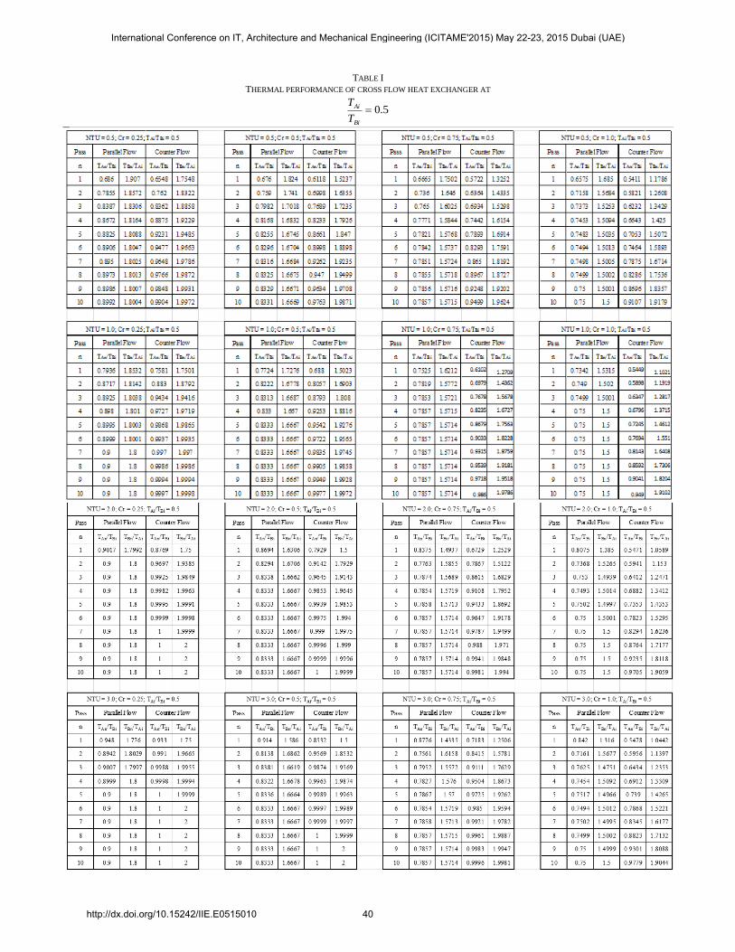
TABLE I
THERMAL PERFORMANCE OF CROSS FLOW HEAT EXCHANGER AT
5.0Bi
Ai
T
T
International Conference on IT, Architecture and Mechanical Engineering (ICITAME'2015) May 22-23, 2015 Dubai (UAE)
http://dx.doi.org/10.15242/IIE.E0515010 40
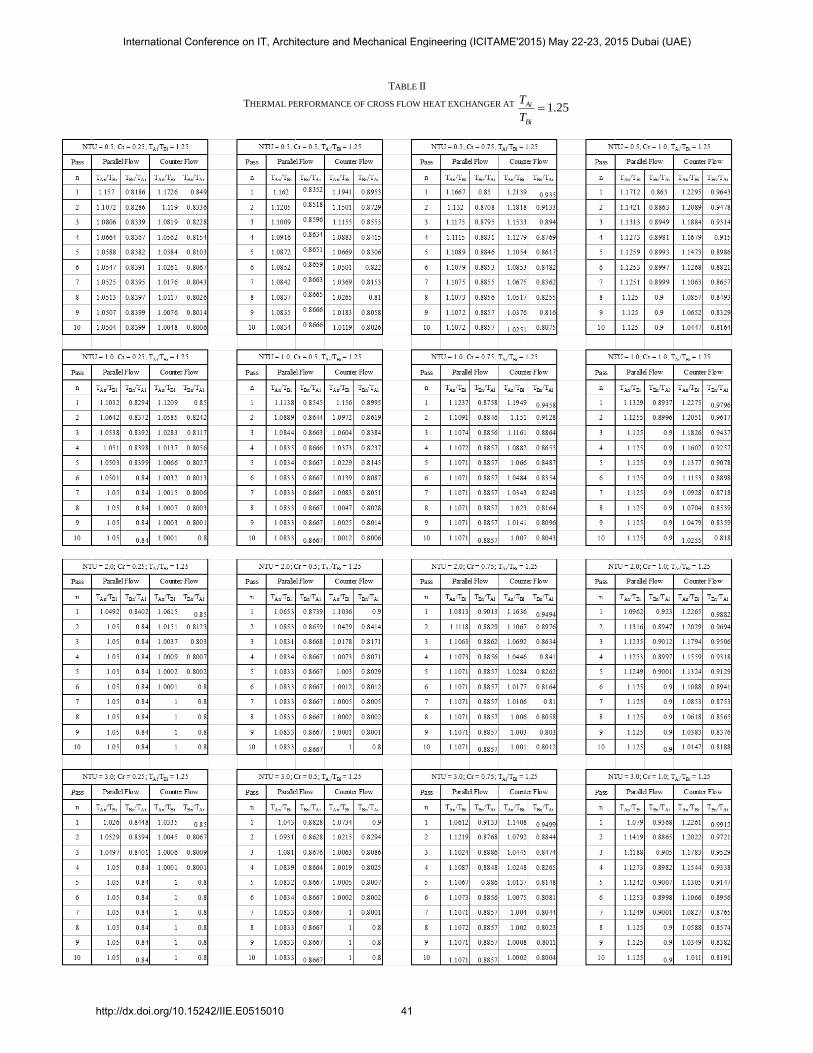
TABLE II
THERMAL PERFORMANCE OF CROSS FLOW HEAT EXCHANGER AT 25.1Bi
Ai
T
T
International Conference on IT, Architecture and Mechanical Engineering (ICITAME'2015) May 22-23, 2015 Dubai (UAE)
http://dx.doi.org/10.15242/IIE.E0515010 41
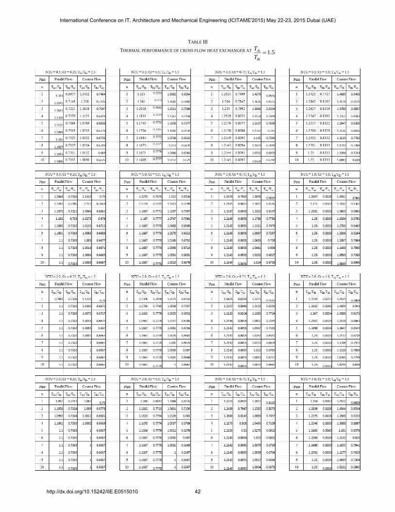
TABLE III
THERMAL PERFORMANCE OF CROSS FLOW HEAT EXCHANGER AT 5.1Bi
Ai
T
T
International Conference on IT, Architecture and Mechanical Engineering (ICITAME'2015) May 22-23, 2015 Dubai (UAE)
http://dx.doi.org/10.15242/IIE.E0515010 42