precision flow heliox - vapotherm precision flow heliox...via nasal cannula. contraindications: ......
TRANSCRIPT
Precision Flow® Heliox Instructions For Use
Page 2 3200003 Rev. B (EN)
Precision Flow® Heliox Packaging contains: Precision Flow® Heliox Unit Instructions For Use Quick Reference Guide Power Cord O2 Sensor cell Heliox & Oxygen Inlet Connectors US ONLY- Heliox and Oxygen Hoses Quick Set Up Sticker (English speaking countries only) Delivery Tube clip
Table of Contents Page
Symbols 3
Section 1 Indications, Warnings and Cautions 4
Section 2 Overview 6
Section 3 Principles of operation 7
Section 4 Controls, displays & connections 8
Section 5 Modes of operation 11
Section 6 Initial assembly 12
Section 7 Setting up 13
Section 8 Adjustments 17
Section 9 Connecting to patient 18
Section 10 Operating guidelines 19
Section 11 Changing the disposable patient circuit 20
Section 12 Alarms 21
Section 13 Shut down 24
Section 14 Routine maintenance 24
Section 15 Cleaning and disinfection 25
Section 16 Specifications 26
Appendix: Audio Tone Characteristics 28 Software modes 29 EMC Guidance 30
3200003 Rev. B (EN) Page 3
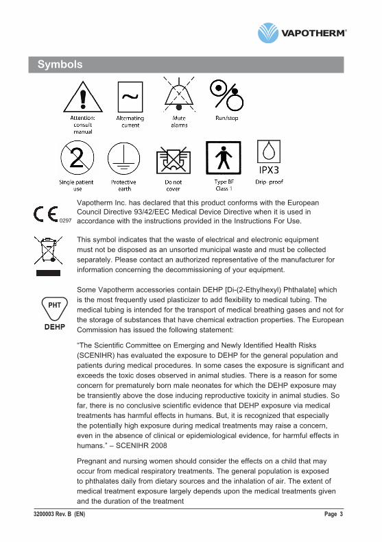
Symbols
Vapotherm Inc. has declared that this product conforms with the EuropeanCouncil Directive 93/42/EEC Medical Device Directive when it is used inaccordance with the instructions provided in the Instructions For Use.
This symbol indicates that the waste of electrical and electronic equipmentmust not be disposed as an unsorted municipal waste and must be collectedseparately. Please contact an authorized representative of the manufacturer forinformation concerning the decommissioning of your equipment.
Some Vapotherm accessories contain DEHP [Di-(2-Ethylhexyl) Phthalate] whichis the most frequently used plasticizer to add flexibility to medical tubing. Themedical tubing is intended for the transport of medical breathing gases and not forthe storage of substances that have chemical extraction properties. The EuropeanCommission has issued the following statement:
“The Scientific Committee on Emerging and Newly Identified Health Risks(SCENIHR) has evaluated the exposure to DEHP for the general population andpatients during medical procedures. In some cases the exposure is significant andexceeds the toxic doses observed in animal studies. There is a reason for someconcern for prematurely born male neonates for which the DEHP exposure maybe transiently above the dose inducing reproductive toxicity in animal studies. Sofar, there is no conclusive scientific evidence that DEHP exposure via medicaltreatments has harmful effects in humans. But, it is recognized that especiallythe potentially high exposure during medical treatments may raise a concern,even in the absence of clinical or epidemiological evidence, for harmful effects inhumans.” – SCENIHR 2008
Pregnant and nursing women should consider the effects on a child that mayoccur from medical respiratory treatments. The general population is exposedto phthalates daily from dietary sources and the inhalation of air. The extent ofmedical treatment exposure largely depends upon the medical treatments givenand the duration of the treatment
0297
Page 4 3200003 Rev. B (EN)
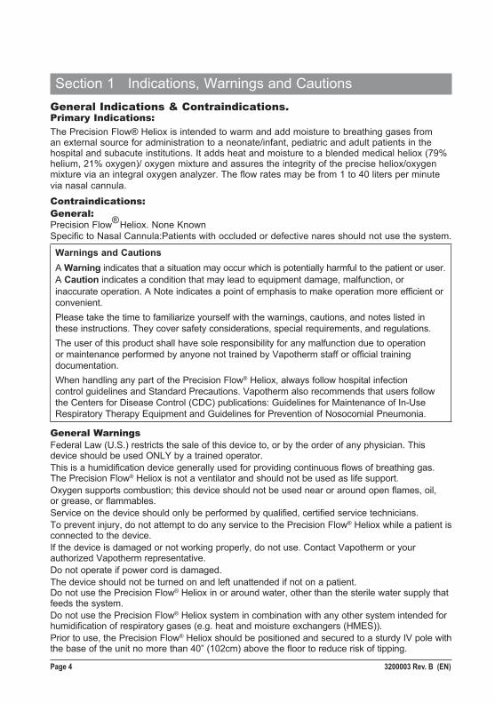
Section 1 Indications, Warnings and CautionsGeneral Indications & Contraindications.Primary Indications:The Precision Flow® Heliox is intended to warm and add moisture to breathing gases from an external source for administration to a neonate/infant, pediatric and adult patients in the hospital and subacute institutions. It adds heat and moisture to a blended medical heliox (79% helium, 21% oxygen)/ oxygen mixture and assures the integrity of the precise heliox/oxygen mixture via an integral oxygen analyzer. The flow rates may be from 1 to 40 liters per minute via nasal cannula.Contraindications:General: Precision Flow® Heliox. None Known Specific to Nasal Cannula:Patients with occluded or defective nares should not use the system.
Warnings and Cautions A Warning indicates that a situation may occur which is potentially harmful to the patient or user.A Caution indicates a condition that may lead to equipment damage, malfunction, or inaccurate operation. A Note indicates a point of emphasis to make operation more efficient or convenient.Please take the time to familiarize yourself with the warnings, cautions, and notes listed in these instructions. They cover safety considerations, special requirements, and regulations.The user of this product shall have sole responsibility for any malfunction due to operation or maintenance performed by anyone not trained by Vapotherm staff or official training documentation.When handling any part of the Precision Flow® Heliox, always follow hospital infection control guidelines and Standard Precautions. Vapotherm also recommends that users follow the Centers for Disease Control (CDC) publications: Guidelines for Maintenance of In-Use Respiratory Therapy Equipment and Guidelines for Prevention of Nosocomial Pneumonia.
General WarningsFederal Law (U.S.) restricts the sale of this device to, or by the order of any physician. This device should be used ONLY by a trained operator.This is a humidification device generally used for providing continuous flows of breathing gas. The Precision Flow® Heliox is not a ventilator and should not be used as life support.Oxygen supports combustion; this device should not be used near or around open flames, oil, or grease, or flammables.Service on the device should only be performed by qualified, certified service technicians.To prevent injury, do not attempt to do any service to the Precision Flow® Heliox while a patient is connected to the device.If the device is damaged or not working properly, do not use. Contact Vapotherm or your authorized Vapotherm representative.Do not operate if power cord is damaged.The device should not be turned on and left unattended if not on a patient. Do not use the Precision Flow® Heliox in or around water, other than the sterile water supply that feeds the system.Do not use the Precision Flow® Heliox system in combination with any other system intended for humidification of respiratory gases (e.g. heat and moisture exchangers (HMES)).Prior to use, the Precision Flow® Heliox should be positioned and secured to a sturdy IV pole with the base of the unit no more than 40” (102cm) above the floor to reduce risk of tipping.
3200003 Rev. B (EN) Page 5
Section 1 Indications, Warnings and Cautions
The Precision Flow® Heliox is designed only for use with a 79% Helium/21% Oxygen Heliox mixture (80:20). Other Helium Oxygen mixtures must not be used.
Make sure all Disposable Patient Circuit connections have been properly secured.
The vapor transfer cartridge, disposable water path and delivery tube are labeled as single patient use only and must be replaced after 30 days use on a single patient: do not attempt to sterilize or reuse and follow all local and federal regulations for disposal. Outside the USA follow national or international regulations.
Failure to utilize sterile water supply or clean gas supply may increase risk of bacterial contamination.
• Use aseptic technique. • Gas supply must be clean dry medical grade gas to prevent harm to the patient and prevent damage to the Precision Flow® Heliox. Use only certified medical grade breathing gases.
Precision Flow® Heliox is not a Continuous Positive Airway Pressure (CPAP) device. There are no controls to deliver or monitor airway pressure. Precision Flow® Heliox should not be used to deliver pressure in a closed system. Never connect the unit to a patient until it reaches set point temperature (temperature display stops flashing). Allow the unit to warm-up to purge condensate and prevent patient discomfort due to cold or partly humidified gas.
Additional patient monitoring is necessary if the Precision Flow® Heliox is used to give supplementary oxygen.
The Precision Flow® Heliox is not MRI compatible.
The unit is provided with a Hospital Grade power cord. Do not use any other cord. Do not use extension cords. For grounding reliability, the cord must be connected to an equivalent receptacle marked “Hospital Grade” or “Hospital Only”. If any doubt exists as to the grounding connection, do not operate the device.
Medical electrical equipment needs special precautions regarding electromagnetic radiation. Portable and mobile RF communications equipment can affect medical equipment and should not be used near the Precision Flow®
Heliox.
The back-up battery is designed for temporary use only, when AC power to the unit has been interrupted. After the battery is fully discharged the device will not operate and patient gas flow will cease. There are no alarms or display indicators after the battery has discharged. The battery is not intended for patient transport.
General CautionsRead and understand the instructions prior to operating the system.
Clamp water supply when not in use, including Standby mode, to prevent damage by water ingress.
Aseptic sterile techniques (including hand washing and avoiding touching connection points) and Standard Precautions should always be followed when handling medical equipment. Standard Precautions should always be followed when coming into contact with patientsDo not cover the unit; blocking the vent may damage the unit.Do not: • Immerse the Precision Flow® Heliox in water. • Steam or gas sterilize the Precision Flow® Heliox. • Wipe with bleach.
Flexible sterile water bags are recommended. If rigid or semi-rigid bottles are used, a Vapotherm approved adapter must be used.
NOTE: The Precision Flow® Heliox may be operated with limited performance at gas inlet pressures as low as 4 psi (28 kPa). However, for the full specified range of gas flows and oxygen percentages, both gas inlet pressures must be 40 psi (276 kPa) or above. Precision Flow® Heliox has not been tested for use in Field transport.
Page 6 3200003 Rev. B (EN)
Section 2 Overview
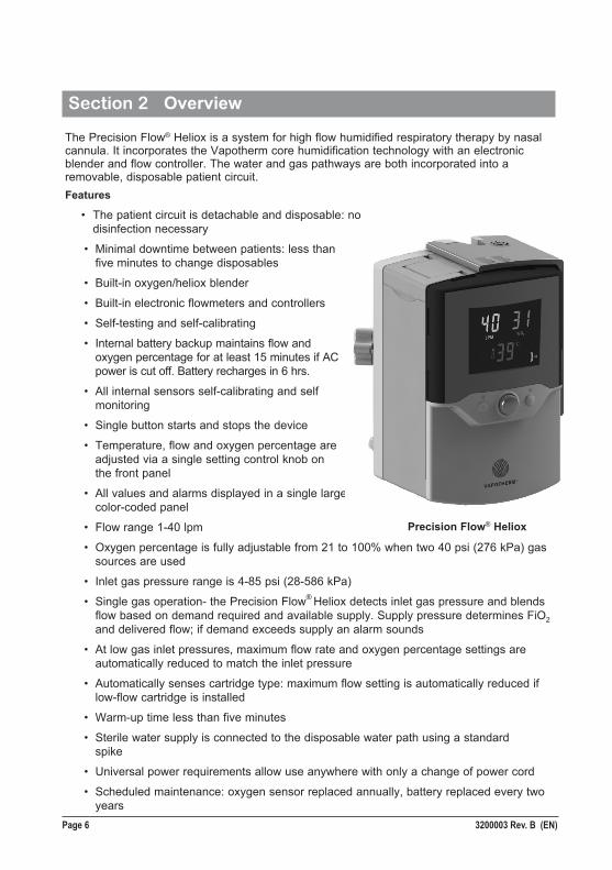
The Precision Flow® Heliox is a system for high flow humidified respiratory therapy by nasal cannula. It incorporates the Vapotherm core humidification technology with an electronic blender and flow controller. The water and gas pathways are both incorporated into a removable, disposable patient circuit.Features
• The patient circuit is detachable and disposable: no disinfection necessary
• Minimal downtime between patients: less than five minutes to change disposables
• Built-in oxygen/heliox blender
• Built-in electronic flowmeters and controllers
• Self-testing and self-calibrating
• Internal battery backup maintains flow and oxygen percentage for at least 15 minutes if AC power is cut off. Battery recharges in 6 hrs.
• All internal sensors self-calibrating and self monitoring
• Single button starts and stops the device
• Temperature, flow and oxygen percentage are adjusted via a single setting control knob on the front panel
• All values and alarms displayed in a single large color-coded panel
• Flow range 1-40 lpm
• Oxygen percentage is fully adjustable from 21 to 100% when two 40 psi (276 kPa) gas sources are used
• Inlet gas pressure range is 4-85 psi (28-586 kPa)
• Single gas operation- the Precision Flow® Heliox detects inlet gas pressure and blends flow based on demand required and available supply. Supply pressure determines FiO2 and delivered flow; if demand exceeds supply an alarm sounds
• At low gas inlet pressures, maximum flow rate and oxygen percentage settings are automatically reduced to match the inlet pressure
• Automatically senses cartridge type: maximum flow setting is automatically reduced if low-flow cartridge is installed
• Warm-up time less than five minutes
• Sterile water supply is connected to the disposable water path using a standard spike
• Universal power requirements allow use anywhere with only a change of power cord
• Scheduled maintenance: oxygen sensor replaced annually, battery replaced every two years
Precision Flow® Heliox
3200003 Rev. B (EN) Page 7
Section 3 Principles of operationThe Precision Flow® Heliox warms and humidifies breathing gas for delivery by nasal cannula at flows from 1 to 40 lpm. The unit incorporates an electronic blender and flow sensors that allow the oxygen percentage and total gas flow to be set independently.The Precision Flow® Heliox consists of two parts:Main unit• The main unit which contains all the electrical and electronic components including the
electronic blender and flow controllers, and remote sensors to monitor the disposable water path. The main unit has no water pathways and the gas pathway contains only dry gas at room temperature, and consequently does not need internal cleaning or disinfection.
• The flow of oxygen and heliox are measured by mass flow sensors. The operating software calculates the required flow of each needed to reach the target flow and oxygen percentage set by the operator. The system controls gas flows accordingly by adjusting proportional solenoid valves on the gas lines. An oxygen sensor monitors the gas mixture and signals any discrepancy between target and measured percentage. The oxygen sensor is automatically calibrated with oxygen at power-up and every 24 hours.
• Firmware running in the main unit uses sensors to monitor gas pressure, water temperature, and to detect air leaks into the disposable patient circuit (bubble detector). Alarms are displayed if any parameters are outside the normal range. Other indicators show low charge in the backup battery, and the type of cartridge installed. See Appendix for a description of the firmware states and transitions.
• After a six hour charging period, an internal battery backup will maintain the set flow and oxygen blend for at least 15 minutes without AC power. The battery is not operator replaceable.
WARNING: The back-up battery is designed for temporary use only, when AC power to the unit has been interrupted. After the battery is fully discharged the device will not operate and patient gas flow will cease. There are no alarms or display indicators after the battery has discharged. The battery is not intended for patient transport.
Disposable patient circuit• The disposable patient circuit (DPC) is comprised of the disposable water path (DWP), vapor transfer cartridge (VTC) and delivery tube. Conditions in the circulating water and gas streams are sensed remotely via the interface between the main unit and the disposable water path.• Vapor transfer cartridge. In the cartridge, blended gas passes through the lumens of hundreds of parallel hollow fibers made of a specially developed polymer. Warm water circulates around the fibers and diffuses as vapor through the fiber material into the gas stream flowing through each fiber. Unlike most humidifiers, there is no direct contact between the water and gas streams. The gas stream leaves the cartridge saturated with vapor at the set temperature. Note: Use only approved cartridges from Vapotherm Inc.• Patient delivery tube.The warmed humidified gas passes through the center of a triple-lumen heated delivery tube. The center lumen is surrounded by two outer lumens circulating warmed water to maintain the temperature of the inner lumen and to minimize rain-out. A proprietary short nasal cannula is connected to the end of the delivery tube and passes the humidified breathing gas to the patient’s nares. It is normal for non-DEHP PVC tubing to appear slightly cloudy, or yellow, especially during longer use or when operated at higher temperatures.• Disposable water path. The disposable water path houses a water reservoir, pump,connections for the vapor transfer cartridge and delivery tube, and sensor interfaces to the main unit. Water is pumped past a heater plate through the outer lumens of the delivery tube. Returning water passes through the outer jacket of the specially designed vapor transfer cartridge where some water is lost as vapor to the gas stream. There is no direct contact between water and gas flows. The water then returns to the pump reservoir. Heater power automatically maintains the set temperature. Water flows into the circuit from the sterile water supply to replace evaporative losses in the vapor transfer cartridge. Air is purged to atmosphere from the circulation via a hydrophobic filter membrane.See Section 5 for a description of the modes of operation.
Page 8 3200003 Rev. B (EN)
Section 4 Controls, displays & connections
13
15
161
12
214
11
3
10
4
9
5
8
6
7
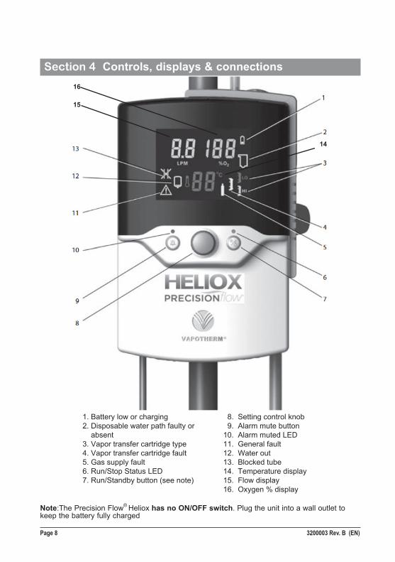
Note:The Precision Flow® Heliox has no ON/OFF switch. Plug the unit into a wall outlet to keep the battery fully charged
1. Battery low or charging 2. Disposable water path faulty or absent 3. Vapor transfer cartridge type 4. Vapor transfer cartridge fault 5. Gas supply fault 6. Run/Stop Status LED 7. Run/Standby button (see note)
8. Setting control knob 9. Alarm mute button10. Alarm muted LED11. General fault12. Water out13. Blocked tube14. Temperature display15. Flow display16. Oxygen % display
16
15
14
3200003 Rev. B (EN) Page 9
Section 4 Controls, displays & connections
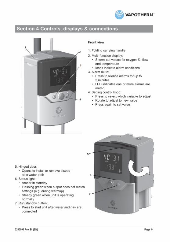
Front view
1. Folding carrying handle2. Multi-function display: • Shows set values for oxygen %, flow and temperature • Icons indicate alarm conditions3. Alarm mute: • Press to silence alarms for up to 2 minutes • LED indicates one or more alarms are muted4. Setting control knob: • Press to select which variable to adjust • Rotate to adjust to new value • Press again to set value
5. Hinged door: • Opens to install or remove dispos- able water path6. Status light: • Amber in standby • Flashing green when output does not match settings (e.g. during warmup) • Steady green when unit is operating normally7. Run/standby button: • Press to start unit after water and gas are connected
12
3
4
5
6
7
Page 10 3200003 Rev. B (EN)
Section 4 Controls, displays & connections
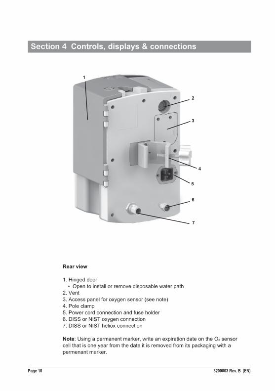
Rear view
1. Hinged door • Open to install or remove disposable water path2. Vent3. Access panel for oxygen sensor (see note)4. Pole clamp5. Power cord connection and fuse holder6. DISS or NIST oxygen connection7. DISS or NIST heliox connection
Note: Using a permanent marker, write an expiration date on the O2 sensor cell that is one year from the date it is removed from its packaging with a permenant marker.
1
2
3
4
5
6
7
3200003 Rev. B (EN) Page 11
Section 4 Controls, displays & connections
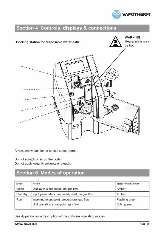
WARNING: Heater plate may be hot!
Docking station for disposable water path
Arrows show location of optical sensor ports.
Do not scratch or scrub the ports. Do not apply organic solvents or bleach.
Section 5 Modes of operation
Mode Action Indicator light color
Sleep Display in sleep mode, no gas flow Amber
Standby Input parameters can be adjusted, no gas flow Amber
Run Warming to set point temperature, gas flowUnit operating at set point, gas flow
Flashing greenSolid green
See Appendix for a description of the software operating modes.
Page 12 3200003 Rev. B (EN)
Section 6 Initial assembly
Certain accessories must be installed in the Precision Flow® Heliox unit before it can be used. These will normally be supplied in a separate package from the main unit as some are country-specific.The power cord plugs into the IEC60320-compliant receptacle on the rear panel.
6a. Oxygen sensor installation
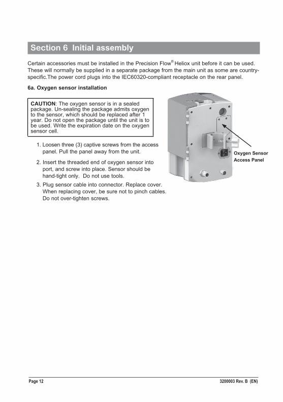
CAUTION: The oxygen sensor is in a sealed package. Un-sealing the package admits oxygen to the sensor, which should be replaced after 1 year. Do not open the package until the unit is to be used. Write the expiration date on the oxygen sensor cell.
1. Loosen three (3) captive screws from the access panel. Pull the panel away from the unit.
2. Insert the threaded end of oxygen sensor into port, and screw into place. Sensor should be hand-tight only. Do not use tools. 3. Plug sensor cable into connector. Replace cover. When replacing cover, be sure not to pinch cables. Do not over-tighten screws.
Oxygen Sensor Access Panel
3200003 Rev. B (EN) Page 13
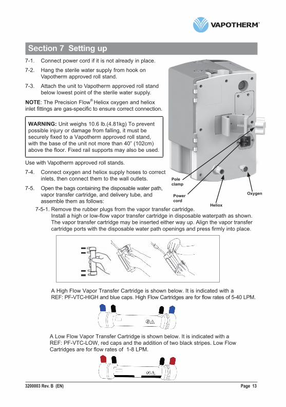
Section 7 Setting up7-1. Connect power cord if it is not already in place.
7-2. Hang the sterile water supply from hook on Vapotherm approved roll stand.
7-3. Attach the unit to Vapotherm approved roll stand below lowest point of the sterile water supply.
NOTE: The Precision Flow® Heliox oxygen and heliox inlet fittings are gas-specific to ensure correct connection.
WARNING: Unit weighs 10.6 lb.(4.81kg) To preventpossible injury or damage from falling, it must besecurely fixed to a Vapotherm approved roll stand, with the base of the unit not more than 40” (102cm) above the floor. Fixed rail supports may also be used.
Use with Vapotherm approved roll stands.
7-4. Connect oxygen and heliox supply hoses to correct inlets, then connect them to the wall outlets.
7-5. Open the bags containing the disposable water path, vapor transfer cartridge, and delivery tube, and assemble them as follows: 7-5-1. Remove the rubber plugs from the vapor transfer cartridge. Install a high or low-flow vapor transfer cartridge in disposable waterpath as shown. The vapor transfer cartridge may be inserted either way up. Align the vapor transfer cartridge ports with the disposable water path openings and press firmly into place.
A High Flow Vapor Transfer Cartridge is shown below. It is indicated with a REF: PF-VTC-HIGH and blue caps. High Flow Cartridges are for flow rates of 5-40 LPM.
A Low Flow Vapor Transfer Cartridge is shown below. It is indicated with a REF: PF-VTC-LOW, red caps and the addition of two black stripes. Low Flow Cartridges are for flow rates of 1-8 LPM.
Oxygen
Heliox
Power cord
Pole clamp
Page 14 3200003 Rev. B (EN)
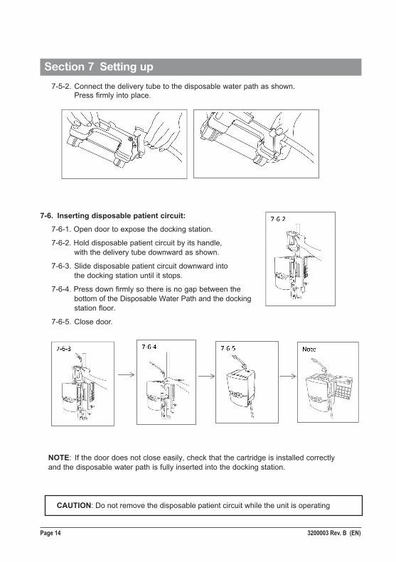
Section 7 Setting up 7-5-2. Connect the delivery tube to the disposable water path as shown. Press firmly into place.
NOTE: If the door does not close easily, check that the cartridge is installed correctly and the disposable water path is fully inserted into the docking station.
CAUTION: Do not remove the disposable patient circuit while the unit is operating
7-6. Inserting disposable patient circuit:
7-6-1. Open door to expose the docking station.
7-6-2. Hold disposable patient circuit by its handle, with the delivery tube downward as shown.
7-6-3. Slide disposable patient circuit downward into the docking station until it stops.
7-6-4. Press down firmly so there is no gap between the bottom of the Disposable Water Path and the docking station floor.
7-6-5. Close door.
3200003 Rev. B (EN) Page 15
Section 7 Setting up7-6-6. General Guidelines
After connecting to the sterile water supply and unclamping the water inlet tube make sure water is flowing into the disposable patient circuit (DPC). Wait approximately 90 seconds (or 180 seconds if using a hard water bottle) before pressing the Run/Standby button. Uncoil and straighten the delivery tube to allow water to more easily flow into the DPC. If air pockets are observed, gently tap the delivery tube to remove the air. Insufficient water flow may lead to a temperature out of range alarm. Holding the distal end of the delivery tube below the Precision Flow® Heliox unit may further assist with water flow into the DPC.
After pressing the Run/Standby button, confirm that water is properly circulating through the machine by making sure the patient delivery tube is warm across the entire length. If good circulation cannot be confirmed, check that the water flow is not obstructed by air bubbles in the water inlet tube connected to the water supply, or in the patient delivery tube. Gently tap and wiggle the tubing, or lift it up and down in order to remove any air seen in the lines.
Reference Section 12 of the Precision Flow® Heliox Instruction For Use for information regarding alarms. Additional alarm information:
If a medium priority Water Out Alarm occurs, this may be due to the sterile water supply being empty, an obstructed inlet tube, or accumulation of air within the DPC. Press Run/Standby button to place the unit in Standby and disconnect patient. If the sterile water supply is empty, replace sterile water supply. If the inlet tube is obstructed, straighten the inlet tube. If necessary, remove and reseat the DPC to ensure that the DPC is fully seated in the Precision Flow® Heliox unit. Press Run/Standby button to restart the unit.
The DPC may be used up to 30 days. Circuit life may be less than 30 days, especially when running at higher flow rates and temperatures which may reduce the useful life of the Vapor Transfer Cartridge. This typically results in the sterile water bag filling up with air and/or a vapor transfer cartridge fault alarm occurring due to gas bubbles in the water path.
After addressing any alarm condition, especially those involving an obstruction of the gas or water flow, check all connections for leaks and make sure the Vapor Transfer Cartridge (VTC) is fully seated into the DPC.
Page 16 3200003 Rev. B (EN)
WARNING: Use high–flow cartridge for flows 5-40 lpm and low-flow cartridge for flows 1-8 lpm.
7-7. Plug in power cord, and check that all the display indicators light. The Precision Flow®
Heliox performs a self-test: • all icons and numeric displays light up for a few seconds • internal sensors and control systems are checked • if no faults are detected the unit enters STANDBY mode • “Water Out” icon indicates there is no water in the disposable water path • status LED is amber
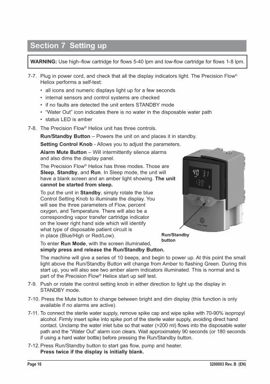
7-8. The Precision Flow® Heliox unit has three controls. Run/Standby Button – Powers the unit on and places it in standby. Setting Control Knob - Allows you to adjust the parameters. Alarm Mute Button – Will intermittently silence alarms and also dims the display panel. The Precision Flow® Heliox has three modes. Those are Sleep, Standby, and Run. In Sleep mode, the unit will have a blank screen and an amber light showing. The unit cannot be started from sleep. To put the unit in Standby, simply rotate the blue Control Setting Knob to illuminate the display. You will see the three parameters of Flow, percent oxygen, and Temperature. There will also be a corresponding vapor transfer cartridge indicator on the lower right hand side which will identify what type of disposable patient circuit is in place (Blue/High or Red/Low). To enter Run Mode, with the screen illuminated, simply press and release the Run/Standby Button. The machine will give a series of 10 beeps, and begin to power up. At this point the small light above the Run/Standby Button will change from Amber to flashing Green. During this start up, you will also see two amber alarm indicators illuminated. This is normal and is part of the Precision Flow® Heliox start up self test. 7-9. Push or rotate the control setting knob in either direction to light up the display in STANDBY mode.
7-10. Press the Mute button to change between bright and dim display (this function is only available if no alarms are active).7-11. To connect the sterile water supply, remove spike cap and wipe spike with 70-90% isopropyl alcohol. Firmly insert spike into spike port of the sterile water supply, avoiding direct hand contact. Unclamp the water inlet tube so that water (>200 ml) flows into the disposable water path and the “Water Out” alarm icon clears. Wait approximately 90 seconds (or 180 seconds if using a hard water bottle) before pressing the Run/Standby button.7-12. Press Run/Standby button to start gas flow, pump and heater. Press twice if the display is initially blank.
Section 7 Setting up
Run/Standby button
3200003 Rev. B (EN) Page 17
Check that the unit beeps while it tests the disposable water path and pump (see Notes below).7-13. If all tests are passed the unit enters RUN mode. Water circulates and fills the delivery tube. The three numeric displays for flow, temperature and oxygen % display initial factory settings or the last settings used. The Status LED flashes then shows continuously green when the unit reaches desired temperature.NOTES on startup:
• When the Run/Standby button is pressed, the unit enters a detection mode. A prompt sounds and the disposable water path icon flashes for approximately five seconds. In this mode the unit inspects the disposable water path to confirm that: a vapor transfer cartridge is present; the disposable water path is present; and the water level is correct. Power is then applied to the water pump. After five seconds the unit checks that the water pump has started and is running at the correct speed. • If the “water out” icon is displayed and accompanied by an alarm, place unit in standby and allow DPC to fully prime. Press run/standby button. • Purging of air bubbles from the circulation can not be seen, because the gas escapes through a membrane at the top of the DWP, not into the water container. • Clamp the inlet tube to stop the flow of water into disposable patient circuit whenever the unit is in standby mode.To adjust settings: See section 8 (Adjustments)For alarms and troubleshooting: See section 12 (Alarms)
Section 7 Setting up
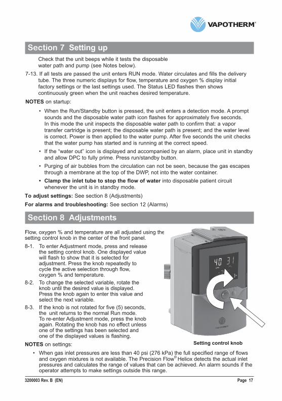
Section 8 AdjustmentsFlow, oxygen % and temperature are all adjusted using the setting control knob in the center of the front panel.8-1. To enter Adjustment mode, press and release the setting control knob. One displayed value will flash to show that it is selected for adjustment. Press the knob repeatedly to cycle the active selection through flow, oxygen % and temperature.8-2. To change the selected variable, rotate the knob until the desired value is displayed. Press the knob again to enter this value and select the next variable.8-3. If the knob is not rotated for five (5) seconds, the unit returns to the normal Run mode. To re-enter Adjustment mode, press the knob again. Rotating the knob has no effect unless one of the settings has been selected and one of the displayed values is flashing.NOTES on settings: • When gas inlet pressures are less than 40 psi (276 kPa) the full specified range of flows and oxygen mixtures is not available. The Precision Flow® Heliox detects the actual inlet pressures and calculates the range of values that can be achieved. An alarm sounds if the operator attempts to make settings outside this range.
Setting control knob
Page 18 3200003 Rev. B (EN)
Section 8 Adjustments
• If oxygen is not connected, the blender setting will be fixed at 21%. If heliox gas is not connected the setting is fixed at 100%. An audio signal sounds if the operator attempts to set any other value.
• If a HIGH-FLOW cartridge is installed the flow can not be set below 5 lpm. • If a LOW-FLOW cartridge is installed the flow can not be set above 8 lpm.NOTES on adjustment:
• Transient temperature changes may occur after rapid changes in flow settings.
• During warmup the temperature display shows actual temperature, not the set value.• In Run mode the display shows the current set values for flow, oxygen % and
temperature.• The setting control knob is sensitive to speed. Rotate quickly for large increments and
slowly for small increments.• If the unit is completely powered down (disconnection of AC power), then the unit will
return to default settings.
Section 9 Connecting to patient
9-1. Wait for desired set temperature to be reached before placing the cannula on the end of the patient delivery tube. The flashing green Status LED becomes steady when the set temperature is reached.9-2. Check water level, temperature display, gas flow rate, and oxygen percentage.
9-3. Size cannula to patient by ensuring that nasal prongs do not fit tightly into nares (1/2 the diameter of the nares).
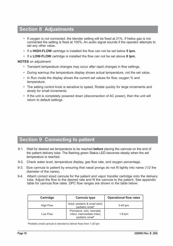
9-4. Attach correct sized cannula for the patient and vapor transfer cartridge onto the delivery tube. Adjust the flow to the desired rate and fit the cannula to the patient. See appendix table for cannula flow rates. DPC flow ranges are shown in the table below:
Cartridge Cannula type Operational flow rates
High Flow Adult, pediatric & small adult, pediatric small* 5-40 lpm
Low Flow Premature, solo, neonatal, infant, intermediate infant,
pediatric small*1-8 lpm
*Pediatric small cannula is intended to deliver flows from 1-20 lpm
3200003 Rev. B (EN) Page 19
Section 9 Connecting to patient
Section 10 Operations: General Guidelines
10-1. Check that water is properly circulating through the disposable by making sure the patient delivery tube is warm across the entire length. If good circulation cannot be confirmed, check that the water flow is not obstructed by air bubbles in the patient delivery tube.10-2. Check that the patient delivery tube will not be occluded by the patient’s position or moving bed structures. 10-3. Take precautions to minimize cooling of the unheated cannula by trying to maintain contact with the patient’s skin and insulating the exposed portion of the cannula with bedding.10-4. During operation the door should be closed.10-5. Check inlet gas traps for contaminates and press valve to empty any condensate, if present.10-6. Check that nothing blocks the vent on the back of the unit.NOTE: Condensation in the cannula may occur in certain ambient conditions at flow rates less than 5 lpm (low flow cartridge) or less than 10 lpm (high flow cartridge). To minimize condensation it is recommended not to set the temperature higher than 34°C, if using flow rates less than 5 lpm.
WARNINGS: • Always follow aseptic technique (including proper hand washing and avoiding direct hand contact with connection points) when setting up the Precision Flow® Heliox and Standard Precautions when placing on a patient. • Cannula should not obstruct more than 50% of the nares of the patient. • Change nasal cannulas when soiled.
NOTES: • The Vapotherm approved interface should be connected to the patient only when the unit has warmed to set temperature (temperature display stops flashing). • Droplets of condensation may appear at the end of patient delivery tube while unit is warming up. This is normal and will stop within a few minutes when set temperature is reached and the cannula is fitted to the patient. • Some condensation around the nose is possible. In addition, a high moisture level may mobilize mucus from nose and sinuses. Make sure patient has a supply of tissues. • The unit should not be placed in Standby mode for extended periods of time. For pauses in therapy, remove cannula from the patient, set the parameters to the lowest available setting and clamp the inlet/spike tube when not in use. To reinitiate therapy, before the cannula is placed on patient, place the unit int RUN mode to clear accumulated condensation.
WARNING: Never connect the unit to a patient until it reaches set point temperature (temperature
display stops flashing). Allow the unit to warm-up to purge condensate and prevent patient discomfort due to cold or partly humidified gas.
Page 20 3200003 Rev. B (EN)
Section 11 Changing the disposable patient circuit
The disposable patient circuit, consisting of the disposable water path, vapor transfer cartridge and delivery tube, is marked for single patient use. They may be used for up to 30 days on a single patient but must then be replaced.
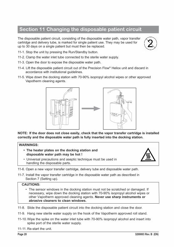
11-1. Stop the unit by pressing the Run/Standby button. 11-2. Clamp the water inlet tube connected to the sterile water supply.11-3. Open the door to expose the disposable water path.
11-4. Lift the disposable patient circuit out of the Precision Flow® Heliox unit and discard in accordance with institutional guidelines.11-5. Wipe down the docking station with 70-90% isopropyl alcohol wipes or other approved Vapotherm cleaning agents.
NOTE: If the door does not close easily, check that the vapor transfer cartridge is installed correctly and the disposable water path is fully inserted into the docking station.
11-8. Slide the disposable patient circuit into the docking station and close the door.
11-9. Hang new sterile water supply on the hook of the Vapotherm approved roll stand.
11-10. Wipe the spike on the water inlet tube with 70-90% isopropyl alcohol and insert into spike port of the sterile water supply.
11-11. Re-start the unit.
WARNINGS: • The heater plates on the docking station and disposable water path may be hot ! • Universal precautions and aseptic technique must be used in handling the disposable parts.
CAUTIONS: • The sensor windows in the docking station must not be scratched or damaged. If necessary, wipe down the docking station with 70-90% isopropyl alcohol wipes or other Vapotherm approved cleaning agents. Never use sharp instruments or abrasive cleaners to clean windows.
11-6. Open a new vapor transfer cartridge, delivery tube and disposable water path.
11-7. Install the vapor transfer cartridge in the disposable water path as described in Section 7 (Setting up).
3200003 Rev. B (EN) Page 21
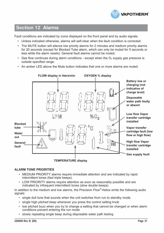
Section 12 AlarmsFault conditions are indicated by icons displayed on the front panel and by audio signals.
• Unless indicated otherwise, alarms will self-clear when the fault condition is corrected.• The MUTE button will silence low priority alarms for 2 minutes and medium priority alarms
for 20 seconds (except for Blocked Tube alarm, which can only be muted for 5 seconds or less while the alarm resets). General fault alarms cannot be muted.
• Gas flow continues during alarm conditions - except when the O2 supply gas pressure is outside specified range.
• An amber LED above the Mute button indicates that one or more alarms are muted.
ALARM TONE PRIORITIES • MEDIUM PRIORITY alarms require immediate attention and are indicated by rapid intermittent tones (fast triple beeps). • LOW PRIORITY alarms require attention as soon as reasonably possible and are indicated by infrequent intermittent tones (slow double beeps).In addition to the medium and low alarms, the Precision Flow® Heliox emits the following audio signals: • single dull tone that sounds when the unit switches from run to standby mode • single high pitched beep whenever you press the control setting knob • low pitched buzz when you try to change a setting that cannot be changed or when alarm conditions prevent entering the run mode • slowly repeating single beep during disposable water path testing
FLOW display in liters/min OXYGEN % display
Battery low or charging (not indicative ofcharge level)
Disposablewater path faultyor absent
Low flow Vapor transfer cartridge installed
Vapor transfer cartridge fault (low flow or high flow)
High flow Vapor transfer cartridge installed
Gas supply fault
Blocked tube
Water out
General fault
TEMPERATURE display
Page 22 3200003 Rev. B (EN)
Section 12 Alarms
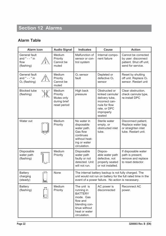
Alarm Table
Alarm icon Audio Signal Indicates Cause Action
General faultand " - - " inflow(flashing)
Medium PriorityCannot be muted
Malfunction of sensor or con-trol system
Internal compo-nent failure
Cannot be corrected by user: disconnect patient. Shut off unit, send for service.
General faultand " - - " inO2 (flashing)
Medium PriorityCannot be muted
O2 sensor fault
Depleted or defective O2 sensor
Reset by shutting off unit. Replace O2 sensor. Restart unit
Blocked tube (flashing)
Medium PriorityMutes only during brief reset period
High back pressure
Obstructed or kinked cannula/delivery tube, incorrect can-nula for flow rate, or DPC improperly seated
Clear obstruction, check cannula type,re-install DPC
Water out Medium Priority
No water in disposable water path. Gas flow continues without heat-ing or water circulation.
Sterile water empty, or obstructed inlet tube.
Disconnect patient. Replace water bag or straighten inlet tube. Restart unit.
Disposable water path (flashing)
Medium Priority
Disposable water path faulty or not detected. Unit will not run.
Dispos-able water path defective, not properly seated or not installed.
If disposable water path is present, remove and replace to reset detector.
Batterycharging(steady)
None The internal battery backup is not fully charged. The unit would not run on battery for the full rated time in the event of a power failure. No action is necessary.
Battery (flashing)
Medium Priority
The unit is running in BATTERY mode. Gas flow and blending con-tinue without heat or water circulation.
AC power is disconnected
Reconnect AC power.
3200003 Rev. B (EN) Page 23
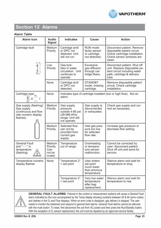
Section 12 AlarmsAlarm Table
GENERAL FAULT ALARMS: Failures in the control or measurement systems will cause a General Fault alarm indicated by this icon accompanied by the Temp display showing numbers between 50 & 84 (error codes) and dashes in the O2 and Flow displays. When an error code is displayed, gas delivery is stopped. The userneeds to monitor the treatment and respond to general fault alarms. General Fault alarms cannot be silencedwith the mute button. To reset, first disconnect the unit from AC power and then press the Run/Standby button. With the exception of O2 sensor replacement, the unit must be repaired by an approved service facility.
Alarm icon Audio Signal
Indicates Cause Action
Cartridge fault
Medium Priority
Cartridge and/or DPC not detected. Unit will not run
RUN mode: faulty sensor or cartridge not detected.
Disconnect patient. Remove disposable patient circuit. Check cartrridge installation. Check sensor windows are clean.
Low Priority
Gas bub-bles in water circulation. Unit continues to operate.
Excessive gas diffusion through car-tridge fibers.
Disconnect patient. Shut off unit. Replace disposable pa-tient circuit including water path, cartridge & delivery tube.
None Cartridge and/or DPC not detected.
STANDBY mode: missing cartridge.
Remove disposable patient circuit. Check cartridge installation.
Cartridge type None Indicates type of cartridge installed (low or high flow). Not an alarm.
Gas supply (flashing)Gas supply (continuous and flow rate numeric display flashes)
Medium Priority
Gas supply pressure outside 4-85 psi (28-586 kPa) range. Unit will not operate.
Gas supply is disconnected or exhausted.
Check gas supply and cor-rect as necessary.
Medium Priority
Selected flow can not be provided from current gas supply.
Inlet gas pres-sure too low for selected flow rate.
Increase gas pressure or decrease flow setting.
General Faultand " - - " in temperature (flashing)
Medium PriorityCan-not be muted
Temperature out of range.
Overheating or tempera-ture sensor malfunction.
Cannot be corrected by user: disconnect patient. Shut off unit and send for service.
Temperature numeric display flashes
None Temperature 2° > set point
User enters set point much lower than previous temperature.
Silence alarm and wait for temperature to drop.
Temperature 2° < set point
Very low water temperature after bag replacement.
Silence alarm and wait for temperature to rise.
Page 24 3200003 Rev. B (EN)
Section 13 Shut down
13-1. Stop the unit by pressing the Run/Standby button. Unit will enter Standby mode.
13-2. Clamp the water inlet tube.
13-3. Open the hinged door, remove the disposable water path with vapor transfer cartridge and delivery tube attached by sliding it upwards out of the docking station.
13-4. Discard all disposables according to hospital guidelines.
13-5. Disconnect unit from AC power.
Note: The Precision Flow® Heliox has no ON/OFF switch. Plug the unit into a wall socket to keep the battery fully charged.
Section 14 Routine maintenance
14.a The internal backup battery should be replaced every two years. Contact Vapotherm for further information.
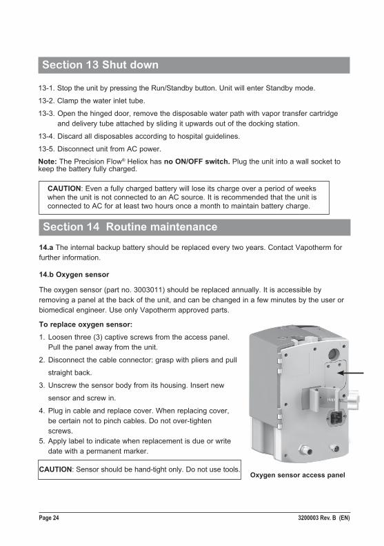
14.b Oxygen sensor
The oxygen sensor (part no. 3003011) should be replaced annually. It is accessible by removing a panel at the back of the unit, and can be changed in a few minutes by the user or biomedical engineer. Use only Vapotherm approved parts.
To replace oxygen sensor:1. Loosen three (3) captive screws from the access panel. Pull the panel away from the unit.
2. Disconnect the cable connector: grasp with pliers and pull
straight back.
3. Unscrew the sensor body from its housing. Insert new
sensor and screw in.
4. Plug in cable and replace cover. When replacing cover, be certain not to pinch cables. Do not over-tighten screws.5. Apply label to indicate when replacement is due or write date with a permanent marker.
CAUTION: Even a fully charged battery will lose its charge over a period of weeks when the unit is not connected to an AC source. It is recommended that the unit is connected to AC for at least two hours once a month to maintain battery charge.
CAUTION: Sensor should be hand-tight only. Do not use tools.Oxygen sensor access panel
3200003 Rev. B (EN) Page 25
Section 14 Routine maintenance
14.c FusesThe mains fuses (two GMA - 3A F250 V, 5 x 20mm) are located next to the power cord inlet. Use a small flat blade screwdriver to pry open the fuse compartment door to access fuses.
NOTE: Vapotherm Preventative Maintenance Kits include all parts require for annual (PM Kit P/N 3100904) and bi-annual (PM Kit P/N 3100906) routine maintenance.
Section 15 Cleaning and disinfectionThe entire disposable patient circuit is disposable and no disinfection is required. The main unit, including the docking station for the disposable water path should be wiped downwith any of the following: 70-90% isopropyl alcohol, 2% (maximum) Chlorine cleaningsolution (Sodium Hypochlorite), or 6% (maximum) Hydrogen Peroxide cleaning solution. In addition, the following detergent wipes may be used to remove any soil from the unit: CaviwipesTM or Sani-ClothTM AF3 Germicidal. Unplug the Precision Flow® Heliox while cleaning and disinfecting.
CAUTION: Do not use organic solvents or abrasive cleaners. Hypochlorite solutions liberate toxic gases such as chlorine when acidified or heated. The reaction with ammonia or wtih substances that can generate ammonia can produce chloramines which are also toxic and have explosive potential. Do not expose the surface of the heater plate on the Precision Flow® Heliox unit to concentrations of Chlorine solution (Sodium Hypochlorite) for a prolonged period of time, as this may cause surface damage to the metal plating.
NOTE: The transparent sensor ports in the docking station must be clean. The unit will not operate if the sensors do not receive a clear signal.
Page 26 3200003 Rev. B (EN)
Section 16 Specifications
PHYSICAL CHARACTERISTICS Dimensions: Height 11.5”(300mm), width 8”(200mm), depth 7”(180mm), excluding Vapotherm approved roll stand clamp. Weight: 10.6 lb (4.81 kg) without disposable patient circuit Circulating Water Volume: 400 ml approx. including delivery tube and vapor transfer cartridge. Mounting: Rear mounted clamp fits Vapotherm approved roll stands up to 1.5”(38mm) diameter. Gas Connections: Standard non-interchangeable fittings for medical heliox and oxygen.FUSES: (Qty 2) GMA 3A F250 V 5mm x 20mm
SYSTEM REQUIREMENTS Power: 100-240VAC, 50-60Hz, approx. 200VA during warm up, approx. 80VA in steady state (depends on flow rate and temperature).
Back-up power: 4.8V nickel-metal hydride battery pack.
Gas supply: Heliox and oxygen at inlet pressures between 4 and 85 psi (28-586 KPa). Heliox supply mixture 79% Helium 21% Oxygen (80/20) NOTE: the full range of flows and oxygen percentage is available only if both gases are present at inlet pressures of at least 40 psi (276 kPa). Unit is calibrated at Vapotherm using 100% O2
Water: Sterile water in pre-filled sealed container.
PERFORMANCE Temperature: Range- 33 to 43°C at exit from the delivery tube, adjustable Resolution- 1°C Accuracy- ± 2°C Warm up time: ± 2°C of 33°C set point < 5 minutes (at ambient 23°C) Humidification: Complies with ISO8185-2007 Respiratory tract humidifiers for medical use, paragraph 101 Oxygen percentage: Range- 21 to 100% O2
Accuracy- ± 2% Resolution- 1% NOTE: At 22% & 23% oxygen blend, the delivered oxygen is 21%. At 98% and 99% oxygen blend, the delivered oxygen is 100%.
3200003 Rev. B (EN) Page 27
Section 16 Specifications
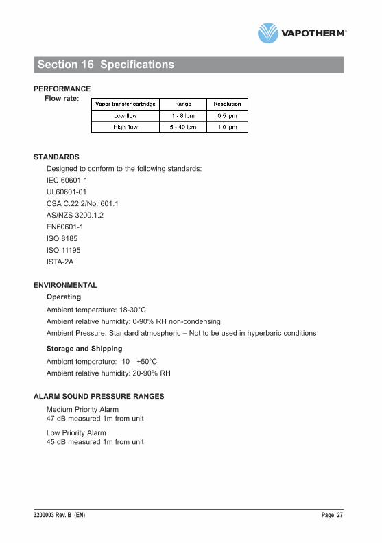
PERFORMANCE Flow rate:
STANDARDS Designed to conform to the following standards: IEC 60601-1 UL60601-01 CSA C.22.2/No. 601.1 AS/NZS 3200.1.2 EN60601-1 ISO 8185 ISO 11195 ISTA-2A
ENVIRONMENTAL Operating
Ambient temperature: 18-30°C Ambient relative humidity: 0-90% RH non-condensing Ambient Pressure: Standard atmospheric – Not to be used in hyperbaric conditions
Storage and Shipping
Ambient temperature: -10 - +50°C Ambient relative humidity: 20-90% RH
ALARM SOUND PRESSURE RANGES
Medium Priority Alarm 47 dB measured 1m from unit
Low Priority Alarm 45 dB measured 1m from unit
Page 28 3200003 Rev. B (EN)
Appendix
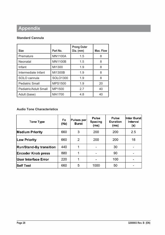
Standard Cannula
Size Part No.Prong Outer Dia. (mm) Max. Flow
Premature MN1100A 1.5 8
Neonatal MN1100B 1.5 8
Infant MI1300 1.9 8
Intermediate Infant MI1300B 1.9 8
SOLO cannula SOLO1300 1.9 8
Pediatric Small MPS1500 1.9 20
Pediatric/Adult Small MP1500 2.7 40
Adult (base) MA1700 4.8 40
Audio Tone Characteristics
3200003 Rev. B (EN) Page 29
Appendix
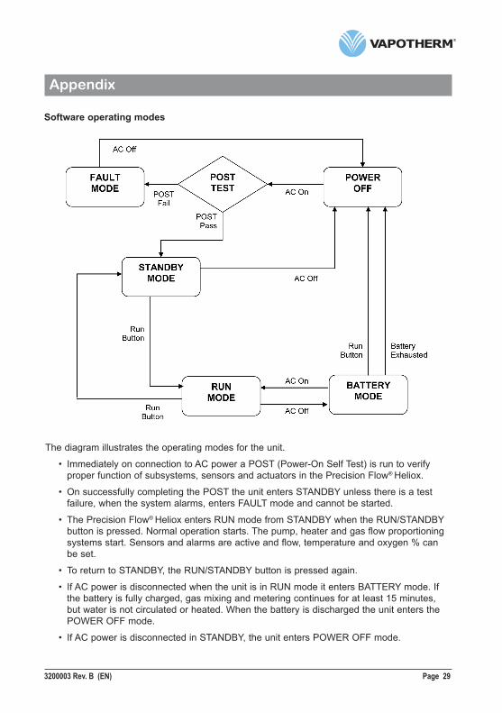
Software operating modes
The diagram illustrates the operating modes for the unit.
• Immediately on connection to AC power a POST (Power-On Self Test) is run to verify proper function of subsystems, sensors and actuators in the Precision Flow® Heliox.
• On successfully completing the POST the unit enters STANDBY unless there is a test failure, when the system alarms, enters FAULT mode and cannot be started.
• The Precision Flow® Heliox enters RUN mode from STANDBY when the RUN/STANDBY button is pressed. Normal operation starts. The pump, heater and gas flow proportioning systems start. Sensors and alarms are active and flow, temperature and oxygen % can be set.
• To return to STANDBY, the RUN/STANDBY button is pressed again.
• If AC power is disconnected when the unit is in RUN mode it enters BATTERY mode. If the battery is fully charged, gas mixing and metering continues for at least 15 minutes, but water is not circulated or heated. When the battery is discharged the unit enters the POWER OFF mode.
• If AC power is disconnected in STANDBY, the unit enters POWER OFF mode.
Page 30 3200003 Rev. B (EN)
Appendix
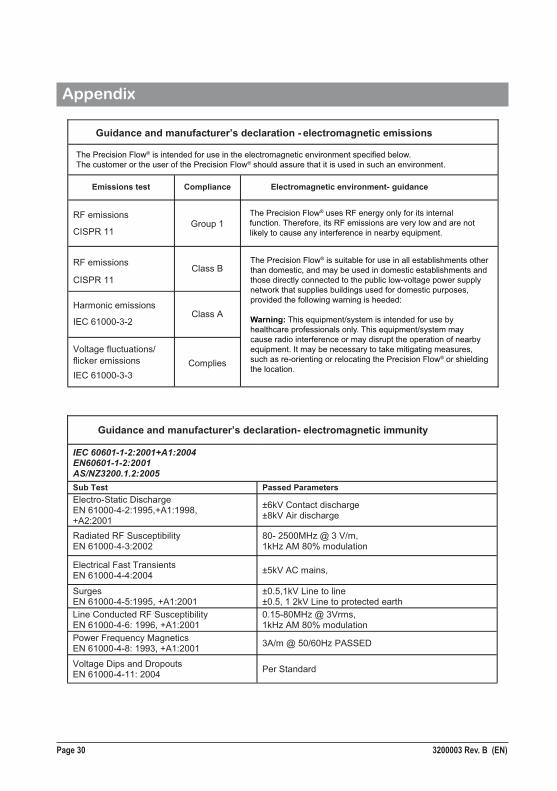
Guidance and manufacturer’s declaration - electromagnetic emissions
Emissions test Compliance Electromagnetic environment- guidance
RF emissions
CISPR 11Group 1
RF emissions
CISPR 11 Class B
Harmonic emissions IEC 61000-3-2
Class A
Voltage fluctuations/flicker emissions
IEC 61000-3-3 Complies
Guidance and manufacturer’s declaration- electromagnetic immunity
IEC 60601-1-2:2001+A1:2004 EN60601-1-2:2001 AS/NZ3200.1.2:2005 Sub Test Passed Parameters Electro-Static Discharge EN 61000-4-2:1995,+A1:1998, +A2:2001
±6kV Contact discharge ±8kV Air discharge
Radiated RF Susceptibility EN 61000-4-3:2002
80- 2500MHz @ 3 V/m, 1kHz AM 80% modulation
Electrical Fast Transients EN 61000-4-4:2004 ±5kV AC mains,
Surges EN 61000-4-5:1995, +A1:2001
±0.5,1kV Line to line ±0.5, 1 2kV Line to protected earth
Line Conducted RF Susceptibility EN 61000-4-6: 1996, +A1:2001
0.15-80MHz @ 3Vrms, 1kHz AM 80% modulation
Power Frequency Magnetics EN 61000-4-8: 1993, +A1:2001 3A/m @ 50/60Hz PASSED
Voltage Dips and Dropouts EN 61000-4-11: 2004 Per Standard
The Precision Flow® uses RF energy only for its internal function. Therefore, its RF emissions are very low and are not likely to cause any interference in nearby equipment.
The Precision Flow® is intended for use in the electromagnetic environment specified below. The customer or the user of the Precision Flow® should assure that it is used in such an environment.
The Precision Flow® is suitable for use in all establishments other than domestic, and may be used in domestic establishments and those directly connected to the public low-voltage power supply network that supplies buildings used for domestic purposes, provided the following warning is heeded:
Warning: This equipment/system is intended for use by healthcare professionals only. This equipment/system may cause radio interference or may disrupt the operation of nearby equipment. It may be necessary to take mitigating measures, such as re-orienting or relocating the Precision Flow® or shielding the location.
3200003 Rev. B (EN) Page 31
Warranty
Vapotherm expressly warrants, for a period of one (1) year from the date of shipment by Vapotherm to the initial purchaser of the Precision Flow® Heliox device (“Customer”) that the Precision Flow® Heliox device shall meet the specifications set forth in the applicable official operating instructions for use provided with each Precision Flow® Heliox device (the “Instructions”). The sole remedy for this warranty is that Vapotherm shall, at its sole option, either refund, repair or replace any or all of any Precision Flow® Heliox device that is defective at no cost to the Customer. Vapotherm shall pay any shipping charges required in repairing or replacing any part or all of a Precision Flow® Heliox device during the warranty period. Thereafter, shipping charges shall be paid by the Customer. Customer shall also be responsible for the cost of labor for repairs. This warranty does not apply to any disposable component to the Precision Flow® Heliox device, including without limitation the disposable patient circuits and hoses supplied with the Precision Flow® Heliox device.
The warranty set forth herein shall become null and void if: (1) the Precision Flow® Heliox device is not used or serviced in accordance with the applicable Instructions or any related preventative maintenance instructions provided with the Precision Flow® Heliox device; or (2) the Precision Flow® Heliox device is opened or tampered with, or if repairs or service are performed or attempted on the Precision Flow® Heliox device by anyone other than Vapotherm or a Vapotherm-certified service center.
EXCEPT AS EXPRESSLY SET FORTH ABOVE, VAPOTHERM MAKES NO WARRANTY, EXPRESS, IMPLIED, STATUTORY OR OTHERWISE, WITH RESPECT TO THE PRODUCTS OR ANY OTHER ITEMS PROVIDED BY VAPOTHERM, AND HEREBY EXPRESSLY DISCLAIMS ANY OTHER FORM OF WARRANTY, INCLUDING, WITHOUT LIMITATION, ANY WARRANTY OF MERCHANTABILITY OR FITNESS FOR A PARTICULAR PURPOSE. THIS STATED WARRANTY IS EXCLUSIVE AND IN LIEU OF ALLL OTHER WARRANTIES PROVIDED BY LAW.
For further information contact:Vapotherm Inc. Corporate Headquarters22 Industrial Drive Exeter, NH 03833USAPhone: 603-658-0011Fax: 603-658-0181www.vapotherm.com
May be patentedwww.vapotherm.com/patents
Technical Support LineDomestic: 855-557-8276International: [email protected]
RMS – UK Limited28 Trinity RoadNailsea, North Somerset BS48 4NU United KingdomPhone: +44-1275-85-88-91Fax: +44-1275-85-88-91

Page 32 3200003 Rev. B (EN)
3200003 Rev. B (EN)
Vapotherm Inc.Corporate Headquarters 22 Industrial Drive Exeter, NH 03833USAPhone: 603-658-0011Fax: 603-658-0181