precision air conditioning - aermecaermec units are fitted with advanced microprocessors which are...
TRANSCRIPT
PRECISION AIR
CONDITIONING
The Aermec solutions for Data Centres

2
ContentsContents
Technical characteristics 4
Main accessories 9
Free Cooling - The use of renewable energy 10
Twin source - Guaranteed continuity of operation 12
P Series - Precision Air ConditioningPerimetral installation (capacity from 6 to 200kW)
14
G Series - Precision Air ConditioningPerimetral installation (capacity from 60 to 300kW)
18
R Series- Precision Air Conditioning In-row installation (capacity from 10 to 40kW)
22
Achieving high effi ciency Data CentresEffi ciency and energy saving
26
Our solutions for Data Centres 28
Aermec 3
Technical characteristics
MICROPROCESSOR TECHNOLOGY
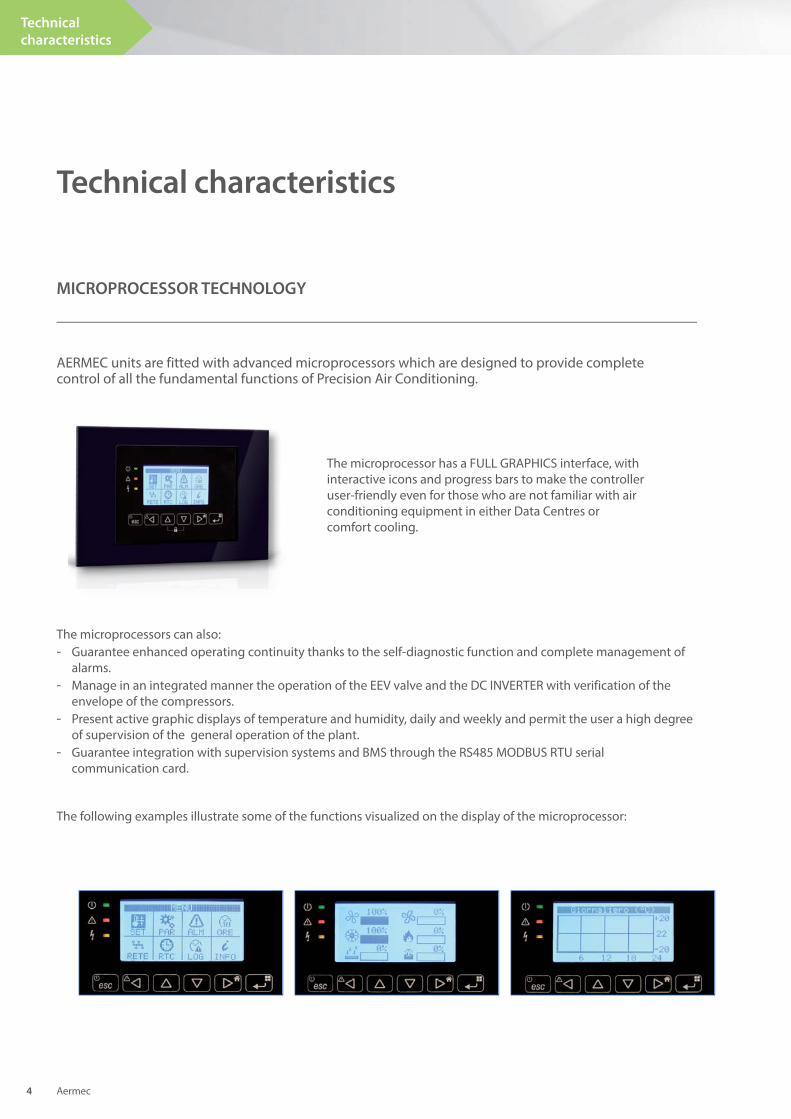
AERMEC units are fitted with advanced microprocessors which are designed to provide complete control of all the fundamental functions of Precision Air Conditioning.
The microprocessor has a FULL GRAPHICS interface, with interactive icons and progress bars to make the controller user-friendly even for those who are not familiar with air conditioning equipment in either Data Centres or comfort cooling.
The microprocessors can also:- Guarantee enhanced operating continuity thanks to the self-diagnostic function and complete management of alarms.- Manage in an integrated manner the operation of the EEV valve and the DC INVERTER with verification of the envelope of the compressors.- Present active graphic displays of temperature and humidity, daily and weekly and permit the user a high degree of supervision of the general operation of the plant.- Guarantee integration with supervision systems and BMS through the RS485 MODBUS RTU serial communication card.
The following examples illustrate some of the functions visualized on the display of the microprocessor:
Aermec 4
Technical
characteristics
The ever-growing necessity to save energy has made the use of high-performance EC Plug Fans indispensable in reducing plant costs.
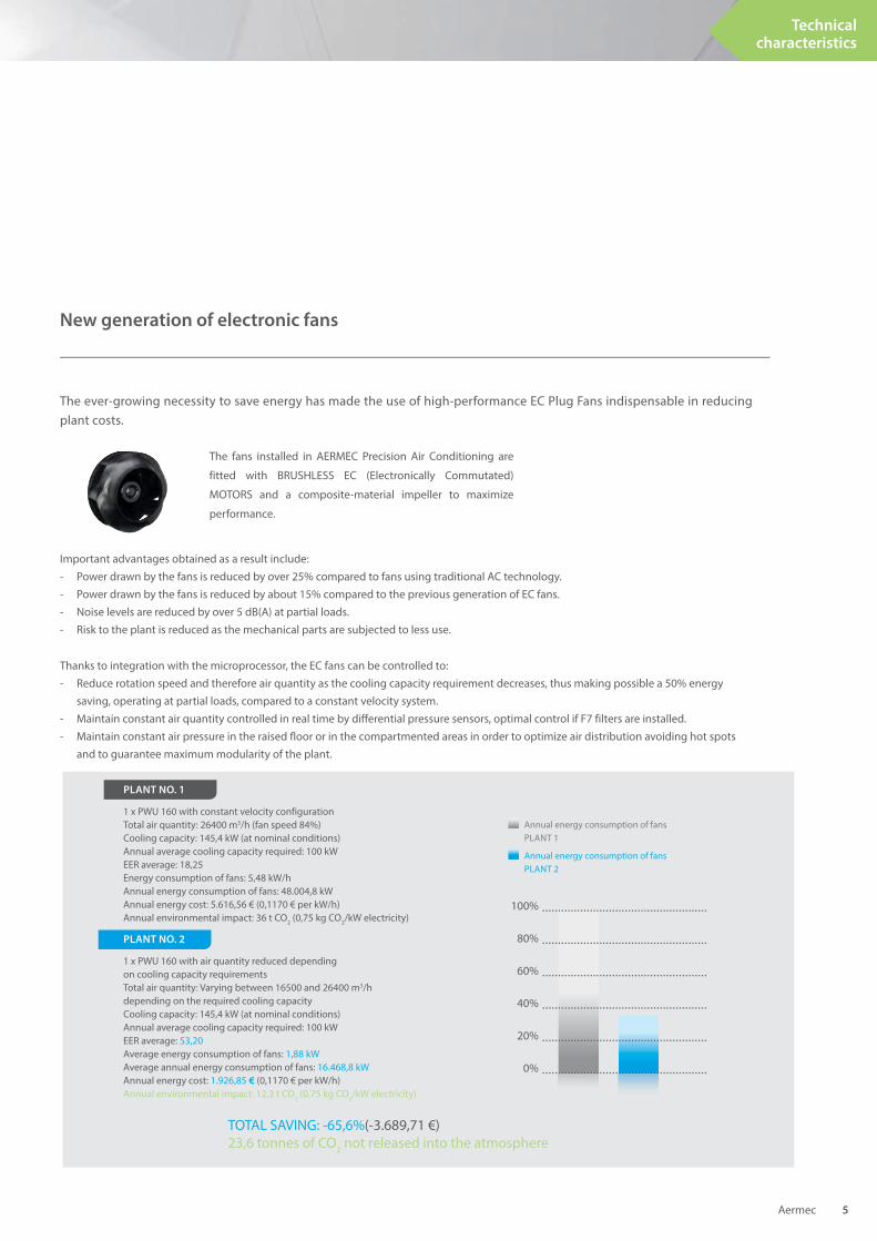
TOTAL SAVING: -65,6%(-3.689,71 €)23,6 tonnes of CO2 not released into the atmosphere
Annual energy consumption of fansPLANT 1
Annual energy consumption of fans PLANT 2
100%
80%
60%
40%
20%
0%
PLANT NO. 1
1 x PWU 160 with constant velocity configurationTotal air quantity: 26400 m3/h (fan speed 84%)Cooling capacity: 145,4 kW (at nominal conditions)Annual average cooling capacity required: 100 kWEER average: 18,25Energy consumption of fans: 5,48 kW/hAnnual energy consumption of fans: 48.004,8 kWAnnual energy cost: 5.616,56 € (0,1170 € per kW/h)Annual environmental impact: 36 t CO2 (0,75 kg CO2/kW electricity)
PLANT NO. 2
1 x PWU 160 with air quantity reduced depending on cooling capacity requirementsTotal air quantity: Varying between 16500 and 26400 m3/h depending on the required cooling capacityCooling capacity: 145,4 kW (at nominal conditions)Annual average cooling capacity required: 100 kWEER average: 53,20Average energy consumption of fans: 1,88 kWAverage annual energy consumption of fans: 16.468,8 kWAnnual energy cost: 1.926,85 € (0,1170 € per kW/h)Annual environmental impact: 12,3 t CO2 (0,75 kg CO2/kW electricity)
The fans installed in AERMEC Precision Air Conditioning are
fitted with BRUSHLESS EC (Electronically Commutated)
MOTORS and a composite-material impeller to maximize
performance.
New generation of electronic fans
Important advantages obtained as a result include: - Power drawn by the fans is reduced by over 25% compared to fans using traditional AC technology.- Power drawn by the fans is reduced by about 15% compared to the previous generation of EC fans.- Noise levels are reduced by over 5 dB(A) at partial loads.- Risk to the plant is reduced as the mechanical parts are subjected to less use.
Thanks to integration with the microprocessor, the EC fans can be controlled to:- Reduce rotation speed and therefore air quantity as the cooling capacity requirement decreases, thus making possible a 50% energy saving, operating at partial loads, compared to a constant velocity system.- Maintain constant air quantity controlled in real time by differential pressure sensors, optimal control if F7 filters are installed.- Maintain constant air pressure in the raised floor or in the compartmented areas in order to optimize air distribution avoiding hot spots and to guarantee maximum modularity of the plant.
Aermec 5
Technical characteristics
Technical characteristics
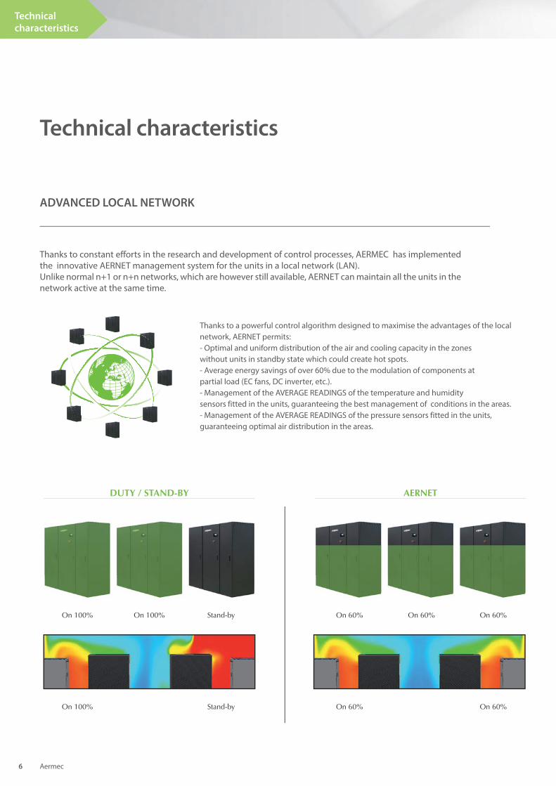
ADVANCED LOCAL NETWORK
Thanks to constant efforts in the research and development of control processes, AERMEC has implemented the innovative AERNET management system for the units in a local network (LAN). Unlike normal n+1 or n+n networks, which are however still available, AERNET can maintain all the units in the network active at the same time.
Aermec 6
Technical
characteristics
Thanks to a powerful control algorithm designed to maximise the advantages of the local network, AERNET permits: - Optimal and uniform distribution of the air and cooling capacity in the zones without units in standby state which could create hot spots.- Average energy savings of over 60% due to the modulation of components at partial load (EC fans, DC inverter, etc.).- Management of the AVERAGE READINGS of the temperature and humidity sensors fitted in the units, guaranteeing the best management of conditions in the areas.- Management of the AVERAGE READINGS of the pressure sensors fitted in the units, guaranteeing optimal air distribution in the areas.
DUTY / STAND-BY AERNET
On 100% Stand-byOn 100%
On 100% Stand-by
On 60% On 60%On 60%
On 60% On 60%
Aermec 7
Technical characteristics
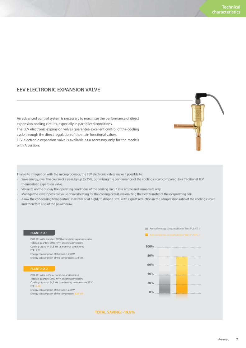
An advanced control system is necessary to maximize the performance of direct expansion cooling circuits, especially in partialized conditions. The EEV electronic expansion valves guarantee excellent control of the cooling cycle through the direct regulation of the main functional values.EEV electronic expansion valve is available as a accessory only for the models with A version.
Thanks to integration with the microprocessor, the EEV electronic valves make it possible to:- Save energy, over the course of a year, by up to 25%, optimizing the performance of the cooling circuit compared to a traditional TEV thermostatic expansion valve.- Visualize on the display the operating conditions of the cooling circuit in a simple and immediate way.- Manage the lowest possible value of overheating for the cooling circuit, maximizing the heat transfer of the evaporating coil.- Allow the condensing temperature, in winter or at night, to drop to 35°C with a great reduction in the compression ratio of the cooling circuit and therefore also of the power draw.
Annual energy consumption of fans PLANT 1
Annual energy consumption of fans PLANT 2
100%
80%
60%
40%
20%
0%
PLANT NO. 1
PXO 211 with standard TEV thermostatic expansion valveTotal air quantity: 7000 m3/h at constant velocityCooling capacity: 21,5 kW (at nominal conditions)EER: 3,26Energy consumption of the fans: 1,23 kWEnergy consumption of the compressor: 5,38 kW
PLANT NO. 2
PXO 211 with EEV electronic expansion valveTotal air quantity: 7000 m3/h at constant velocityCooling capacity: 24,5 kW (condensing temperature 35°C)EER: 4,42
Energy consumption of the fans: 1,23 kWEnergy consumption of the compressor: 4,31 kW
TOTAL SAVING: -19,8%
EEV ELECTRONIC EXPANSION VALVE
Main
accessories
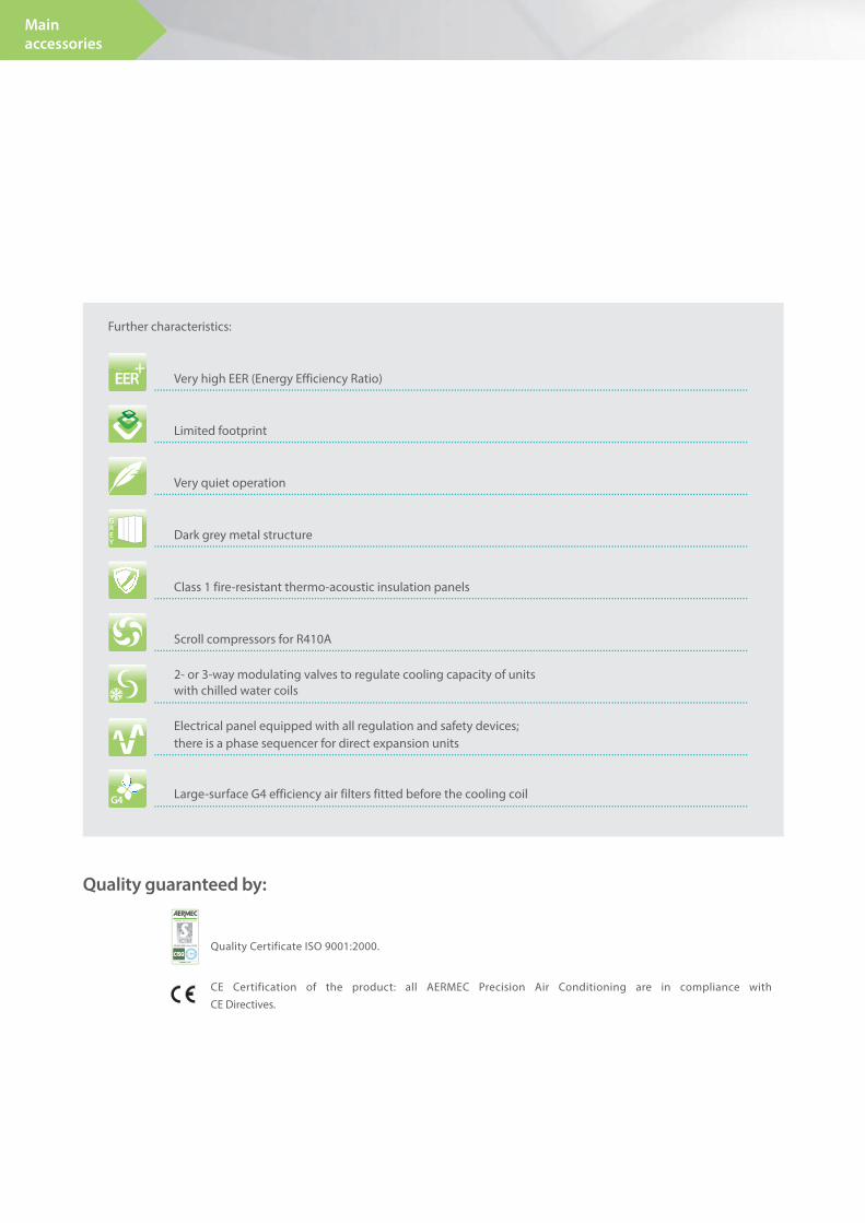
Further characteristics:
Very high EER (Energy Efficiency Ratio)
Limited footprint
Very quiet operation
Dark grey metal structure
Class 1 fire-resistant thermo-acoustic insulation panels
Scroll compressors for R410A
2- or 3-way modulating valves to regulate cooling capacity of unitswith chilled water coils
Electrical panel equipped with all regulation and safety devices; there is a phase sequencer for direct expansion units
Large-surface G4 efficiency air filters fitted before the cooling coil
Quality guaranteed by:
Quality Certificate ISO 9001:2000.
CE Certification of the product: all AERMEC Precision Air Conditioning are in compliance with CE Directives.
EER+
G4
GREY
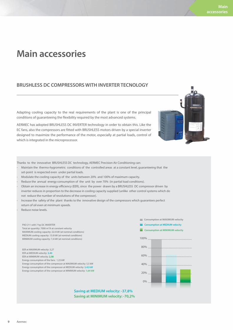
Adapting cooling capacity to the real requirements of the plant is one of the principal conditions of guaranteeing the flexibility required by the most advanced systems.
AERMEC has adopted BRUSHLESS DC INVERTER technology in order to obtain this. Like the EC fans, also the compressors are fitted with BRUSHLESS motors driven by a special inverter designed to maximize the performance of the motor, especially at partial loads, control of which is integrated in the microprocessor.
Consumption at MEDIUM velocity
Consumption at MINIMUM velocity
100%
80%
60%
40%
20%
0%
PXO 211 with 7 hp DC INVERTER Total air quantity: 7000 m3/h at constant velocityMAXIMUM cooling capacity: 22.0 kW (at nominal conditions)MEDIUM cooling capacity: 15.8 kW (at nominal conditions)MINIMUM cooling capacity: 7,4 kW (at nominal conditions)
EER at MAXIMUM velocity: 3,27EER at MEDIUM velocity: 3,40
EER at MINIMUM velocity: 2,58
Energy consumption of the fans: 1,23 kWEnergy consumption of the compressor at MAXIMUM velocity: 5,5 kWEnergy consumption of the compressor at MEDIUM velocity: 3,42 kW
Energy consumption of the compressor at MINIMUM velocity: 1,64 kW
Thanks to the innovative BRUSHLESS DC technology, AERMEC Precision Air Conditioning can:- Maintain the thermo-hygrometric conditions of the controlled areas at a constant level, guaranteeing that the set-point is respected even under partial loads. - Modulate the cooling capacity of the units between 20% and 100% of maximum capacity.- Reduce the annual energy consumption of the unit by over 70% (in partial load conditions).- Obtain an increase in energy efficiency (EER), since the power drawn by a BRUSHLESS DC compressor driven by inverter reduces in proportion to the decrease in cooling capacity supplied (unlike other control systems which do not reduce the number of revolutions of the compressor).- Increase the safety of the plant thanks to the innovative design of the compressors which guarantees perfect return of oil even at minimum speeds.- Reduce noise levels.
Saving at MEDIUM velocity: -37,8%
Saving at MINIMUM velocity: -70,2%
Consumption at MAXIMUM velocity
Main accessories
BRUSHLESS DC COMPRESSORS WITH INVERTER TECNOLOGY
Aermec 9
Main
accessories
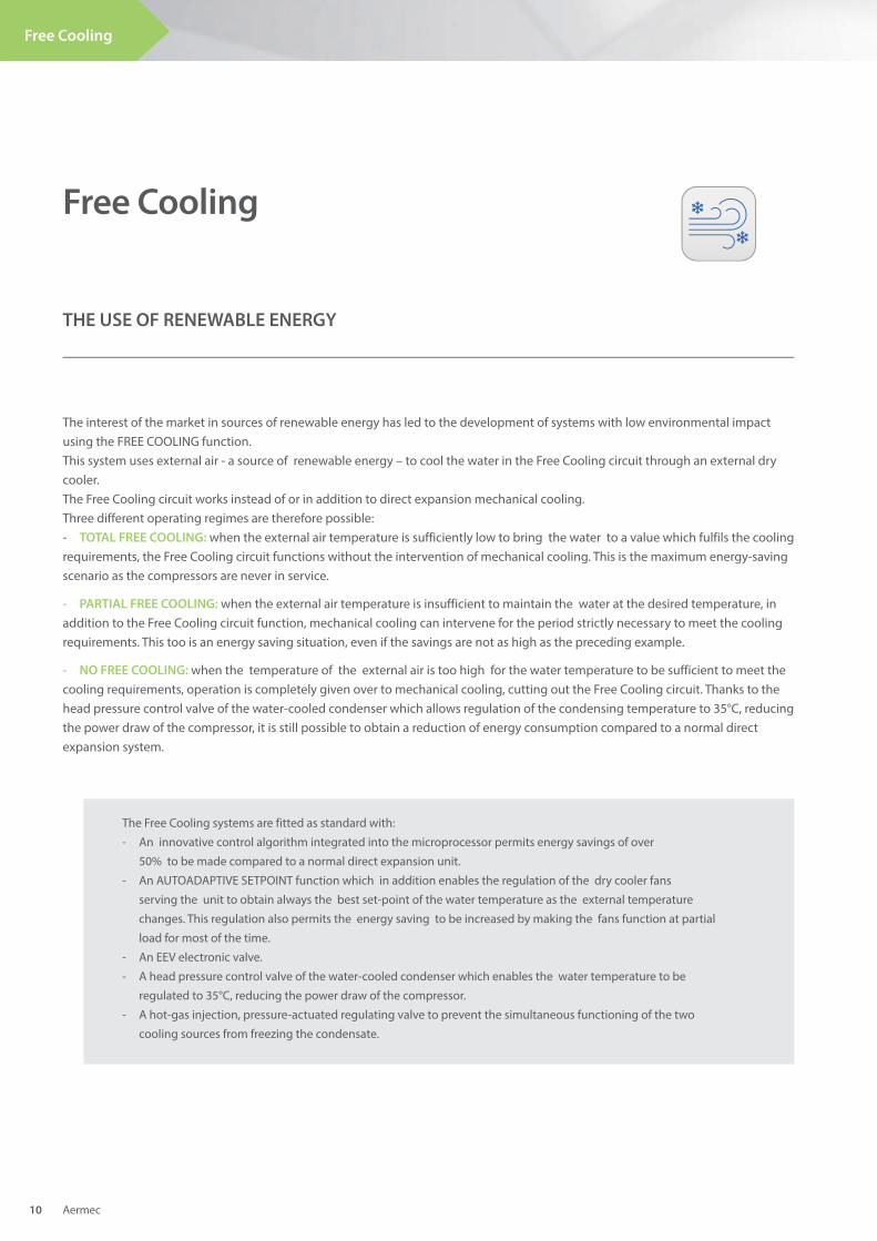
The interest of the market in sources of renewable energy has led to the development of systems with low environmental impact using the FREE COOLING function. This system uses external air - a source of renewable energy – to cool the water in the Free Cooling circuit through an external dry cooler.The Free Cooling circuit works instead of or in addition to direct expansion mechanical cooling.Three different operating regimes are therefore possible:- TOTAL FREE COOLING: when the external air temperature is sufficiently low to bring the water to a value which fulfils the cooling requirements, the Free Cooling circuit functions without the intervention of mechanical cooling. This is the maximum energy-saving scenario as the compressors are never in service.
- PARTIAL FREE COOLING: when the external air temperature is insufficient to maintain the water at the desired temperature, in addition to the Free Cooling circuit function, mechanical cooling can intervene for the period strictly necessary to meet the cooling requirements. This too is an energy saving situation, even if the savings are not as high as the preceding example.
- NO FREE COOLING: when the temperature of the external air is too high for the water temperature to be sufficient to meet the cooling requirements, operation is completely given over to mechanical cooling, cutting out the Free Cooling circuit. Thanks to the head pressure control valve of the water-cooled condenser which allows regulation of the condensing temperature to 35°C, reducing the power draw of the compressor, it is still possible to obtain a reduction of energy consumption compared to a normal direct expansion system.
The Free Cooling systems are fitted as standard with:
- An innovative control algorithm integrated into the microprocessor permits energy savings of over
50% to be made compared to a normal direct expansion unit.
- An AUTOADAPTIVE SETPOINT function which in addition enables the regulation of the dry cooler fans
serving the unit to obtain always the best set-point of the water temperature as the external temperature
changes. This regulation also permits the energy saving to be increased by making the fans function at partial
load for most of the time.
- An EEV electronic valve.
- A head pressure control valve of the water-cooled condenser which enables the water temperature to be
regulated to 35°C, reducing the power draw of the compressor.
- A hot-gas injection, pressure-actuated regulating valve to prevent the simultaneous functioning of the two
cooling sources from freezing the condensate.
Free Cooling
THE USE OF RENEWABLE ENERGY
Aermec 10
Free Cooling
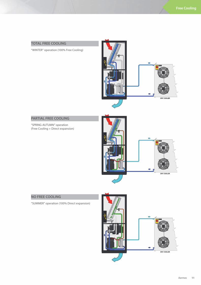
“SPRING-AUTUMN” operation(Free Cooling + Direct expansion)
“SUMMER” operation (100% Direct expansion)
TOTAL FREE COOLING
“WINTER” operation (100% Free Cooling)
PARTIAL FREE COOLING
NO FREE COOLING
Aermec 11
Free Cooling
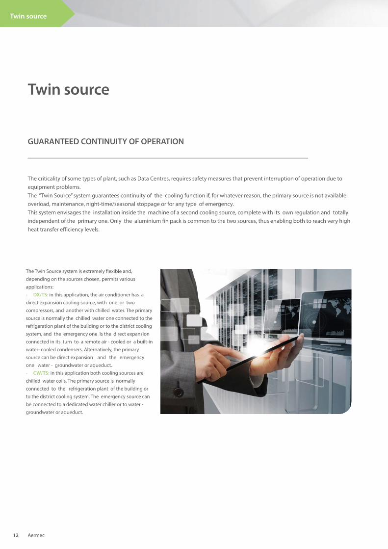
The Twin Source system is extremely flexible and, depending on the sources chosen, permits various applications:- DX/TS: in this application, the air conditioner has a direct expansion cooling source, with one or two compressors, and another with chilled water. The primary source is normally the chilled water one connected to the refrigeration plant of the building or to the district cooling system, and the emergency one is the direct expansion connected in its turn to a remote air - cooled or a built-in water- cooled condensers. Alternatively, the primary source can be direct expansion and the emergency one water - groundwater or aqueduct.- CW/TS: in this application both cooling sources are chilled water coils. The primary source is normally connected to the refrigeration plant of the building or to the district cooling system. The emergency source can be connected to a dedicated water chiller or to water - groundwater or aqueduct.
Twin source
GUARANTEED CONTINUITY OF OPERATION
The criticality of some types of plant, such as Data Centres, requires safety measures that prevent interruption of operation due to equipment problems. The “Twin Source” system guarantees continuity of the cooling function if, for whatever reason, the primary source is not available: overload, maintenance, night-time/seasonal stoppage or for any type of emergency.This system envisages the installation inside the machine of a second cooling source, complete with its own regulation and totally independent of the primary one. Only the aluminium fin pack is common to the two sources, thus enabling both to reach very high heat transfer efficiency levels.
Aermec 12
Twin source
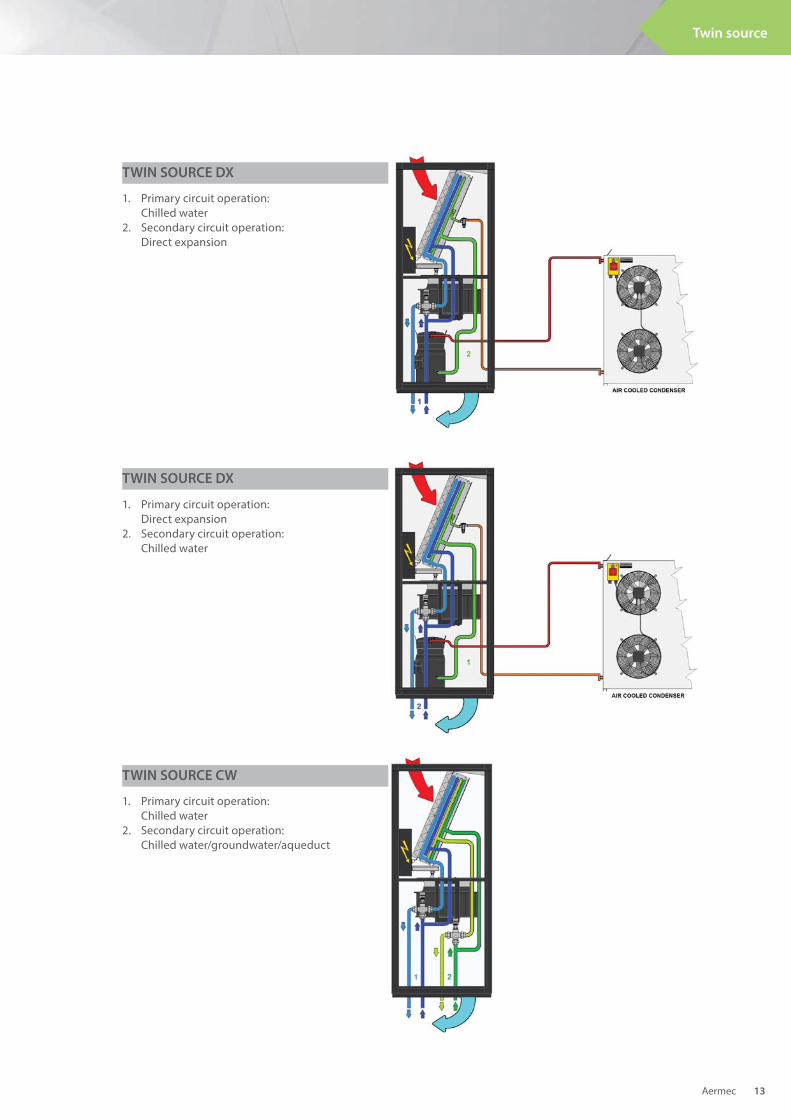
1. Primary circuit operation: Direct expansion2. Secondary circuit operation: Chilled water
1. Primary circuit operation: Chilled water2. Secondary circuit operation: Chilled water/groundwater/aqueduct
1. Primary circuit operation: Chilled water2. Secondary circuit operation: Direct expansion
TWIN SOURCE DX
TWIN SOURCE DX
TWIN SOURCE CW
Aermec 13
Twin source
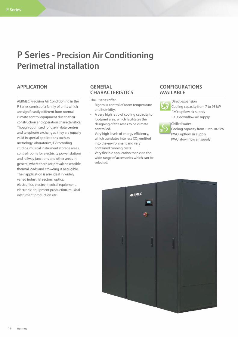
AERMEC Precision Air Conditioning in the P Series consist of a family of units which are significantly different from normal climate control equipment due to their construction and operation characteristics. Though optimized for use in data centres and telephone exchanges, they are equally valid in special applications such as metrology laboratories, TV recording studios, musical instrument storage areas, control rooms for electricity power stations and railway junctions and other areas in general where there are prevalent sensible thermal loads and crowding is negligible. Their application is also ideal in widely varied industrial sectors: optics, electronics, electro-medical equipment, electronic equipment production, musical instrument production etc.
P Series
P Series - Precision Air Conditioning
Perimetral installation
APPLICATION
Direct expansionCooling capacity from 7 to 95 kW PXO: upflow air supply PXU: downflow air supply
CONFIGURATIONS AVAILABLE
The P series offer:- Rigorous control of room temperature and humidity.- A very high ratio of cooling capacity to footprint area, which facilitates the designing of the areas to be climate controlled.- Very high levels of energy efficiency, which translates into less CO2 emitted into the environment and very contained running costs.- Very flexible application thanks to the wide range of accessories which can be selected.
GENERAL CHARACTERISTICS
Aermec 14
Chilled waterCooling capacity from 10 to 187 kWPWO: upflow air supplyPWU: downflow air supply
P Series
Aermec 15
Direct expansion• DC brushless compressors with inverter
control• Electric power supply line for remote
condenser• Electric power supply line with speed
adjustment for remote condenser• Condenser adjustment with 0-10V signal
for remote condenser with EC fans• “LT Kit” for external air low temperature
functioning with remote condenser• Increased liquid receiver• Non-return valves on the flow and liquid
lines• Water condenser• Water condenser with valve for adjusting
the condensation temperature• “HT Kit” for functioning with high
condensation temperatures
Chilled water• Two ways modulating valves• Inlet and outlet water temperature probes• “Power Valve” Kit
Heating• Low thermal inertia electric batteries
with differentiated stages regulation• Low thermal inertia electric batteries
with modulating regulation (available on request on some models only)
• Water heating batteries with 2 or 3 ways modulating valve (available on request on some models only)
Humidifi cation• Room humidity probe• Flow humidity probe• Immersed electrode humidifie
Mechanicals and structural• Condensation drain pump• Condensation and humidifier drain
pump• Flow overpressure dampers• M5 (EU5) efficiency air filter on air supply• Soundproofed duct piece on flow• Flow plenum with adjustable grills.• Height adjustable support for raised
floor installation• Grilled panels for front flow• Closed panels for downwards air intake• Panels with “sandwich” counter-panels
(available on request on some models only)
• Panels with increased soundproof upholstery (available on request on some models only)
Electrical• Alternative available voltages:
460V/3ph/60Hz - 380V/3ph/60Hz - 230V/3ph/60Hz
• Electric power supply line without neutral
• “Basic” version automatic transfer switch (ATS)
• “Advanced” version automatic transfer switch (ATS)
Adjustment• Constant flow rate ventilation
adjustment• Constant pressure ventilation
adjustment• Local area network configuration and
cable• User terminal for remote installation• Flooding detection system
ACCESSORIES
Note: For further information, refer to the selection program.
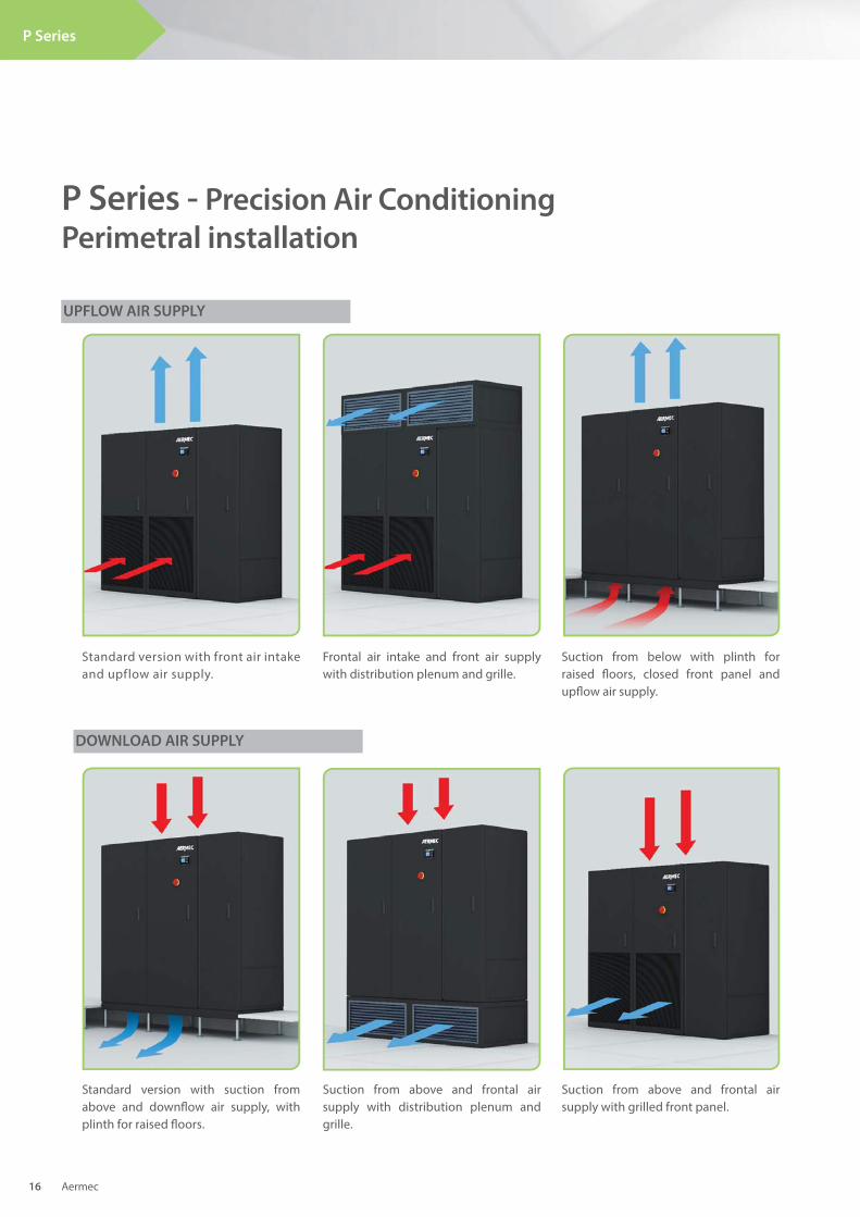
Standard version with front air intake and upflow air supply.
Frontal air intake and front air supply with distribution plenum and grille.
Suction from below with plinth for raised fl oors, closed front panel and upfl ow air supply.
Standard version with suction from above and downfl ow air supply, with plinth for raised fl oors.
Suction from above and frontal air supply with distribution plenum and grille.
Suction from above and frontal air supply with grilled front panel.
UPFLOW AIR SUPPLY
P Series - Precision Air Conditioning
Perimetral installation
DOWNLOAD AIR SUPPLY
Aermec 16
P Series
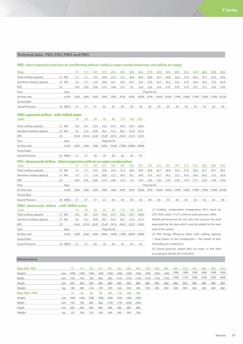
Technical data - PXO, PXU, PWO and PWU
Aermec 17
P Series
PXO : direct expansion precision air conditioning with air-cooled or water-cooled condensers and upfl ow air supply
Sizes 71 111 141 211 251 301 302 361 372 422 461 491 512 612 662 852 932
Total cooling capacity (1) kW 7,7 11,1 14,5 20,8 25,3 31,2 30,6 36,6 38,8 42,7 46,9 52,3 51,6 63,2 67,7 87,3 94,2
Sensitive cooling capacity (1) kW 7,4 11,1 12,8 20,8 22,7 30,3 30,1 36,6 33,6 42,7 45,3 52,3 47,4 62,6 64,5 73,2 85,4
EER (2) 3,69 3,26 3,36 3,12 3,06 3,13 3,2 3,24 3,22 3,22 3,37 3,47 3,14 3,21 3,17 3,29 3,59
Fans type Plug fan EC
Air flow rate m3/h 2200 3200 3200 7000 7000 8700 8700 14500 8700 14500 14500 17900 14500 17900 17900 17900 20700
Sound data
Sound Pressure (3) dB(A) 51 57 57 62 62 60 60 65 65 65 65 62 65 62 62 62 60
PWO :upwards airfl ow - with chilled waterSizes 10 20 30 50 80 110 160 220
Total cooling capacity (1) kW 10,0 18,1 32,4 43,6 67,4 93,4 142,1 186,4
Sensitive cooling capacity (1) kW 9,2 15,5 29,8 38,1 62,5 80,7 122,9 161,3
EER (2) 34,42 29,24 22,83 21,48 24,16 24,02 23,33 24,02
Fans type Plug fan EC
Air flow rate m3/h 2200 3200 7400 8200 15400 17000 26000 34000
Sound data
Sound Pressure (3) dB(A) 51 57 63 59 66 62 64 65
PXU : downwards airfl ow - direct expansion with air or water condensationSizes 71 111 141 211 251 301 302 361 372 422 461 491 512 612 662 852 932
Total cooling capacity (1) kW 7,7 11,1 14,5 20,8 25,3 31,2 30,6 36,6 38,8 42,7 46,9 52,3 51,6 63,2 67,7 87,3 94,2
Sensitive cooling capacity (1) kW 7,4 11,1 12,8 20,8 22,7 30,3 30,1 36,6 33,6 42,7 45,3 52,3 47,4 62,6 64,5 73,2 85,4
EER (2) 3,69 3,25 3,36 3,12 3,06 3,13 3,2 3,24 3,03 3,22 3,37 3,47 3,14 3,17 3,25 3,29 3,59
Fans type Plug fan EC
Air flow rate m3/h 2200 3200 3200 7000 7000 8700 8700 14500 8700 14500 14500 17900 14500 17900 17900 17900 20700
Sound data
Sound Pressure (3) dB(A) 51 57 57 62 62 60 60 65 60 65 65 62 65 62 62 62 60
PWU : downwards airfl ow - with chilled waterSizes 10 20 30 50 80 110 160 220
Total cooling capacity (1) kW 10,2 18,1 32,4 43,6 67,4 93,4 142,1 186,9
Sensitive cooling capacity (1) kW 9,2 15,5 29,8 38,1 62,5 80,7 122,9 161,3
EER (2) 34,42 29,24 22,83 21,48 24,16 24,02 23,33 24,02
Fans type Plug fan EC
Air flow rate m3/h 2200 3200 7400 8200 15400 17000 26000 34000
Sound data
Sound Pressure (3) dB(A) 51 57 63 59 66 62 64 65
(1) Cooling: condensation temperature 45°C; input air
24°C-45%; water 7/12°C; external static pressure: 30Pa.
Stated performances do not take into account the heat
generated by the fans which must be added to the heat
load of the system.
(2) EER: Energy Efficiency Ratio; total cooling capacity
/ input power to the compressors + the power of fans
(excluding air condensers)
(3) Sound pressure: stated data 2m away, in free field
according to UNI EN ISO 3744:2010
Mod. PXO - PXU 71 111 141 211 251 301 302 361 372 422 461 491 512 612 662 852 932
Height mm 1990 1990 1990 1990 1990 1990 1990 1990 1990 1990 1990 1990 1990 1990 1990 1990 1990
Width mm 750 750 750 860 860 1410 1410 1750 1410 1750 1750 2300 1750 2300 2300 2300 2640
Depth mm 600 600 600 880 880 880 880 880 880 880 880 880 880 880 880 880 880
Weight kg 180 200 210 270 270 320 340 440 350 450 450 540 500 640 640 660 860
Mod. PWO - PWU 10 20 30 50 80 110 160 220
Height mm 1990 1990 1990 1990 1990 1990 1990 1990
Width mm 750 750 860 860 1750 1750 2640 3495
Depth mm 600 600 880 880 880 880 880 880
Weight kg 155 160 220 240 340 360 540 700
Dimensions
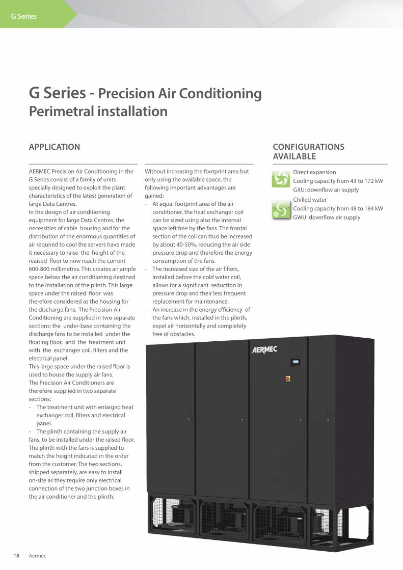
AERMEC Precision Air Conditioning in the G Series consist of a family of units specially designed to exploit the plant characteristics of the latest generation of large Data Centres. In the design of air conditioning equipment for large Data Centres, the necessities of cable housing and for the distribution of the enormous quantities of air required to cool the servers have made it necessary to raise the height of the reaised floor to now reach the current 600-800 millimetres. This creates an ample space below the air conditioning destined to the installation of the plinth. This large space under the raised floor was therefore considered as the housing for the discharge fans. The Precision Air Conditioning are supplied in two separate sections: the under-base containing the discharge fans to be installed under the floating floor, and the treatment unit with the exchanger coil, filters and the electrical panel.This large space under the raised floor is used to house the supply air fans. The Precision Air Conditioners are therefore supplied in two separate sections: - The treatment unit with enlarged heat exchanger coil, filters and electrical panel.- The plinth containing the supply air fans, to be installed under the raised floor. The plinth with the fans is supplied to match the height indicated in the order from the customer. The two sections, shipped separately, are easy to install on-site as they require only electrical connection of the two junction boxes in the air conditioner and the plinth.
G Series - Precision Air Conditioning
Perimetral installation
APPLICATION
Direct expansion Cooling capacity from 43 to 172 kW GXU: downflow air supply
CONFIGURATIONS AVAILABLE
Without increasing the footprint area but only using the available space, the following important advantages are gained:- At equal footprint area of the air conditioner, the heat exchanger coil can be sized using also the internal space left free by the fans. The frontal section of the coil can thus be increased by about 40-50%, reducing the air side pressure drop and therefore the energy consumption of the fans.- The increased size of the air filters, installed before the cold water coil, allows for a significant reduction in pressure drop and their less frequent replacement for maintenance.- An increase in the energy efficiency of the fans which, installed in the plinth, expel air horizontally and completely free of obstacles.
Aermec 18
G Series
Chilled waterCooling capacity from 48 to 184 kWGWU: downflow air supply
p y p y free of obstacles.
Aermec 19
G Series
ACCESSORIES
Direct expansion• Brushless DC compressors with inverter
adjustment• Power supply line for remote condenser• Power supply line for remote condenser
speed adjuster• Condenser adjustment with 0-10V signal
remote condenser with EC fans• “Kit LT” for operating with low outside air
temperature with the remote condenser• Oversized liquid receiver tank• Non-return valves on the delivery and
liquid lines• Water condenser• Water condenser with condensing
temperature adjustment valve• “Kit HT” for operating with high
condensation temperatures
Cooled water• Modulating 3-way valves• Water temperature probes on inlet & outlet• “Power valve” kit
Heating• Electrical coils with low thermal inertia
and adjustment over differential stages• Electrical coils with low thermal inertia
and modulating adjustment (available on request only for certain models)
• Water-based heating coils with 2 or 3 way modulating (available on request only for certain models)
Humidifi cation• Ambient humidity probe• Delivery humidity probe• Immersed electrode humidifie
Mechanicals and structural• Condensate discharge pump• Condensate discharge and humidifier
pump• Overpressure gate valves on delivery• Air filter on intake, efficiency M5 (EU5)• Intake plenum• Ventilated plenum with panelling for
front or rear delivery• Ventilated plenum with panelling for
bottom delivery (installation above raised flooring)
• Panels with counter-panelling, “sandwich” type
• Panels with over-sized acoustic finishing
Electrical• Alternative voltages available:
460V/3ph/60Hz - 380V/3ph/60Hz - 230V/3ph/60Hz
• Power supply line without neutral• Automatic line selector switch (ATS) -
“Basic” version• Automatic line selector switch (ATS) -
“Advanced” version
Regulation• Ventilation adjustment at constant capacity• Ventilation adjustment at constant pressure• Setting and cable for local network connection• User terminal for remote installation• Flooding detection system
Note: For further information, refer to the selection program.
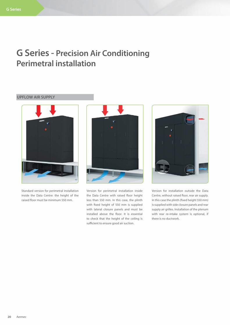
Standard version for perimetral installation inside the Data Centre: the height of the raised fl oor must be minimum 550 mm.
Version for perimetral installation inside the Data Centre with raised fl oor height less than 550 mm. In this case, the plinth with fi xed height of 550 mm is supplied with lateral closure panels and must be installed above the fl oor. It is essential to check that the height of the ceiling is suffi cient to ensure good air suction.
Version for installation outside the Data Centre, without raised fl oor, rear air supply. In this case the plinth (fi xed height 550 mm) is supplied with side closure panels and rear supply air grilles. Installation of the plenum with rear re-intake system is optional, if there is no ductwork.
G Series - Precision Air Conditioning
Perimetral installation
UPFLOW AIR SUPPLY
Aermec 20
G Series
GWU: chilled water coil precision air conditioning with downfl ow air supply
Technical data - GXU and GWU
Aermec 21
G Series
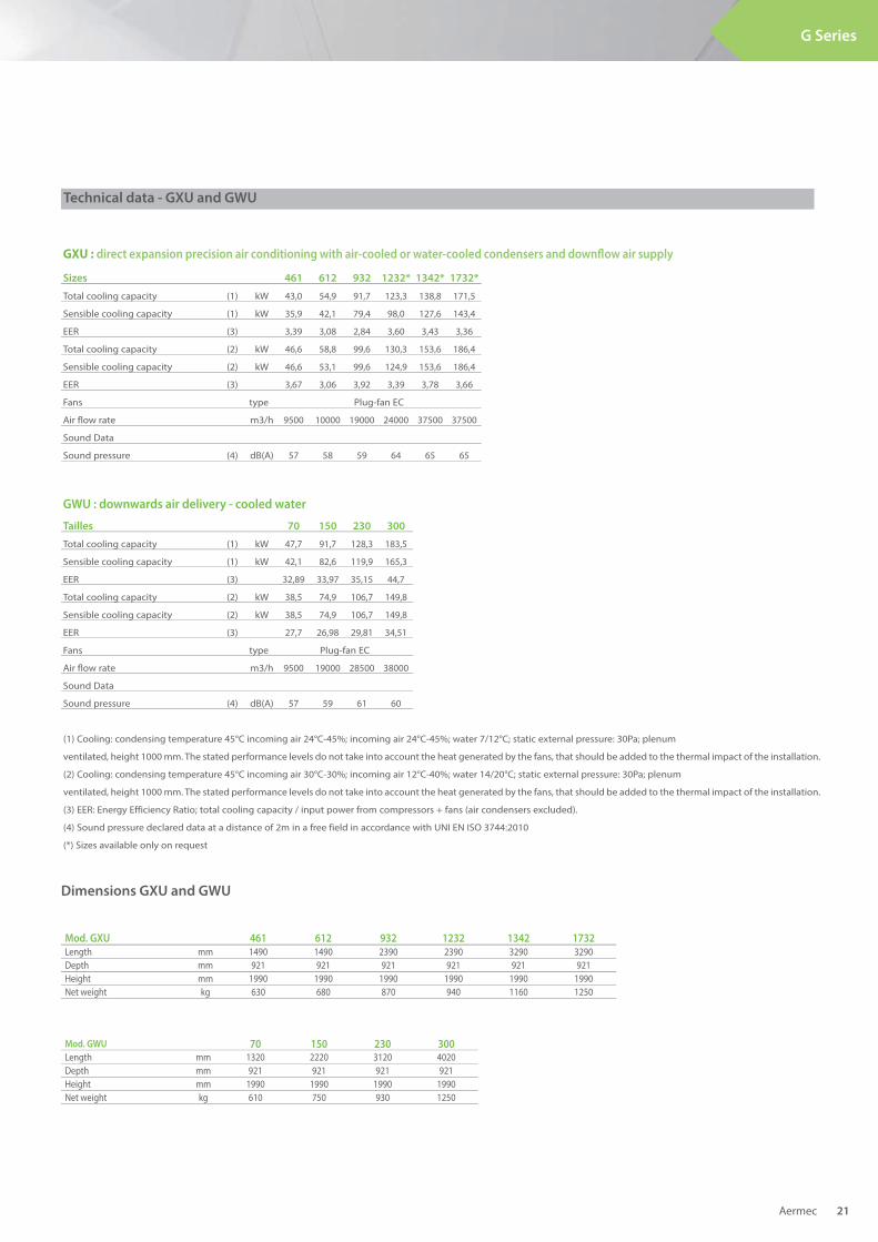
GXU : direct expansion precision air conditioning with air-cooled or water-cooled condensers and downfl ow air supply
Sizes 461 612 932 1232* 1342* 1732*
Total cooling capacity (1) kW 43,0 54,9 91,7 123,3 138,8 171,5
Sensible cooling capacity (1) kW 35,9 42,1 79,4 98,0 127,6 143,4
EER (3) 3,39 3,08 2,84 3,60 3,43 3,36
Total cooling capacity (2) kW 46,6 58,8 99,6 130,3 153,6 186,4
Sensible cooling capacity (2) kW 46,6 53,1 99,6 124,9 153,6 186,4
EER (3) 3,67 3,06 3,92 3,39 3,78 3,66
Fans type Plug-fan EC
Air flow rate m3/h 9500 10000 19000 24000 37500 37500
Sound Data
Sound pressure (4) dB(A) 57 58 59 64 65 65
GWU : downwards air delivery - cooled water
Tailles 70 150 230 300
Total cooling capacity (1) kW 47,7 91,7 128,3 183,5
Sensible cooling capacity (1) kW 42,1 82,6 119,9 165,3
EER (3) 32,89 33,97 35,15 44,7
Total cooling capacity (2) kW 38,5 74,9 106,7 149,8
Sensible cooling capacity (2) kW 38,5 74,9 106,7 149,8
EER (3) 27,7 26,98 29,81 34,51
Fans type Plug-fan EC
Air flow rate m3/h 9500 19000 28500 38000
Sound Data
Sound pressure (4) dB(A) 57 59 61 60
(1) Cooling: condensing temperature 45°C incoming air 24°C-45%; incoming air 24°C-45%; water 7/12°C; static external pressure: 30Pa; plenum
ventilated, height 1000 mm. The stated performance levels do not take into account the heat generated by the fans, that should be added to the thermal impact of the installation.
(2) Cooling: condensing temperature 45°C incoming air 30°C-30%; incoming air 12°C-40%; water 14/20°C; static external pressure: 30Pa; plenum
ventilated, height 1000 mm. The stated performance levels do not take into account the heat generated by the fans, that should be added to the thermal impact of the installation.
(3) EER: Energy Efficiency Ratio; total cooling capacity / input power from compressors + fans (air condensers excluded).
(4) Sound pressure declared data at a distance of 2m in a free field in accordance with UNI EN ISO 3744:2010
(*) Sizes available only on request
Mod. GXU 461 612 932 1232 1342 1732
Length mm 1490 1490 2390 2390 3290 3290Depth mm 921 921 921 921 921 921Height mm 1990 1990 1990 1990 1990 1990Net weight kg 630 680 870 940 1160 1250
Mod. GWU 70 150 230 300Length mm 1320 2220 3120 4020Depth mm 921 921 921 921Height mm 1990 1990 1990 1990Net weight kg 610 750 930 1250
Dimensions GXU and GWU
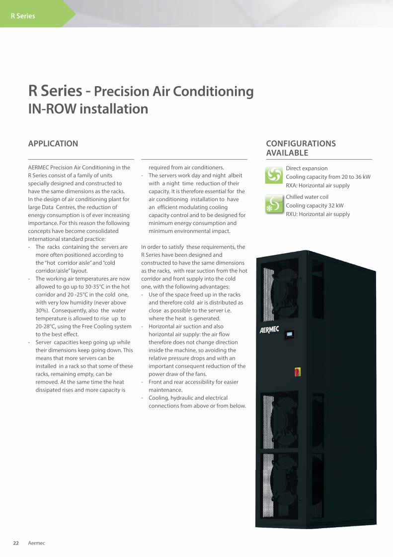
AERMEC Precision Air Conditioning in the R Series consist of a family of units specially designed and constructed to have the same dimensions as the racks. In the design of air conditioning plant for large Data Centres, the reduction of energy consumption is of ever increasing importance. For this reason the following concepts have become consolidated international standard practice:- The racks containing the servers are more often positioned according to the “hot corridor aisle” and “cold corridor/aisle” layout.- The working air temperatures are now allowed to go up to 30-35°C in the hot corridor and 20 -25°C in the cold one, with very low humidity (never above 30%). Consequently, also the water temperature is allowed to rise up to 20-28°C, using the Free Cooling system to the best effect.- Server capacities keep going up while their dimensions keep going down. This means that more servers can be installed in a rack so that some of these racks, remaining empty, can be removed. At the same time the heat dissipated rises and more capacity is
R Series - Precision Air Conditioning
IN-ROW installation
APPLICATION
Direct expansion Cooling capacity from 20 to 36 kW RXA: Horizontal air supply
CONFIGURATIONS AVAILABLE
required from air conditioners.- The servers work day and night albeit with a night time reduction of their capacity. It is therefore essential for the air conditioning installation to have an efficient modulating cooling capacity control and to be designed for minimum energy consumption and minimum environmental impact.
In order to satisfy these requirements, the R Series have been designed and constructed to have the same dimensions as the racks, with rear suction from the hot corridor and front supply into the cold one, with the following advantages:- Use of the space freed up in the racks and therefore cold air is distributed as close as possible to the server i.e. where the heat is generated.- Horizontal air suction and also horizontal air supply: the air flow therefore does not change direction inside the machine, so avoiding the relative pressure drops and with an important consequent reduction of the power draw of the fans. - Front and rear accessibility for easier maintenance.- Cooling, hydraulic and electrical connections from above or from below.
Aermec 22
R Series
Chilled water coil Cooling capacity 32 kWRXU: Horizontal air supply
t
.
Aermec 23
R Series
ACCESSORIES
Direct expansion• Power supply line for remote condenser• Power supply line for remote condenser
speed adjuster• Condenser adjustment with 0-10V signal
remote condenser with EC fans• “Kit LT” for operating with low outside air
temperature with the remote condenser• Oversized liquid receiver tank• Non-return valves on the delivery and
liquid lines• Water condenser• Water condenser with condensing
temperature adjustment valve
Chilled water• Modulating 2-way valves• Water temperature probes on inlet & outlet• “Power valve” kit
Heating• Electrical coils with low thermal inertia
and adjustment over differential stages
Humidifi cation• Ambient humidity probe• Delivery humidity probe• Immersed electrode humidifier
Mechanicals and structural• Condensate discharge pump• Air filter on intake, efficiency M5 (EU5)• Closed front panel for side delivery• Closed side panels for front delivery• Handling wheels
Electrical• Alternative voltages available:
460V/3ph/60Hz - 380V/3ph/60Hz - 230V/3ph/60Hz
• Power supply line without neutral• Automatic line selector switch (ATS) -
“Basic” version• Automatic line selector switch (ATS) -
“Advanced” version
Regulation• Ventilation adjustment at constant
capacity• Ventilation adjustment at constant
pressure• Setting and cable for local network
connection• User terminal for remote installation• Flooding detection system
Note: For further information, refer to the selection program.
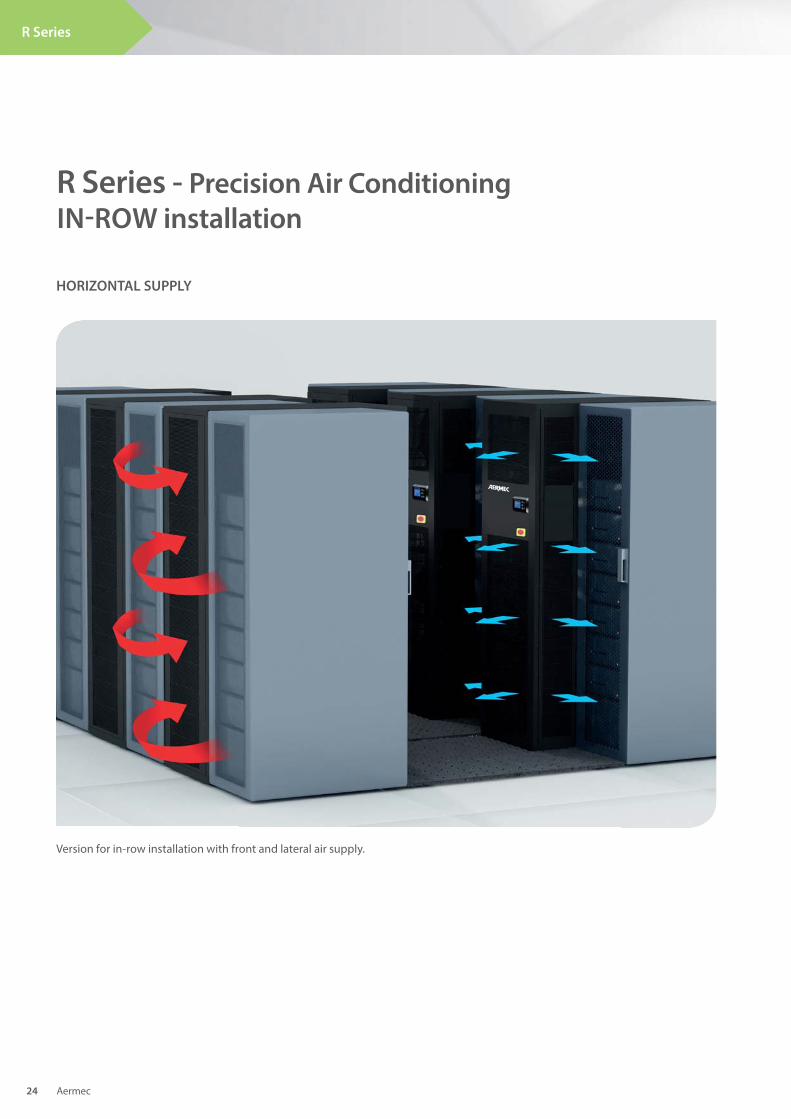
Version for in-row installation with front and lateral air supply.
R Series - Precision Air Conditioning
IN-ROW installation
HORIZONTAL SUPPLY
Aermec 24
R Series
RXU: chilled water coil precision air conditioning with horizontal air supply
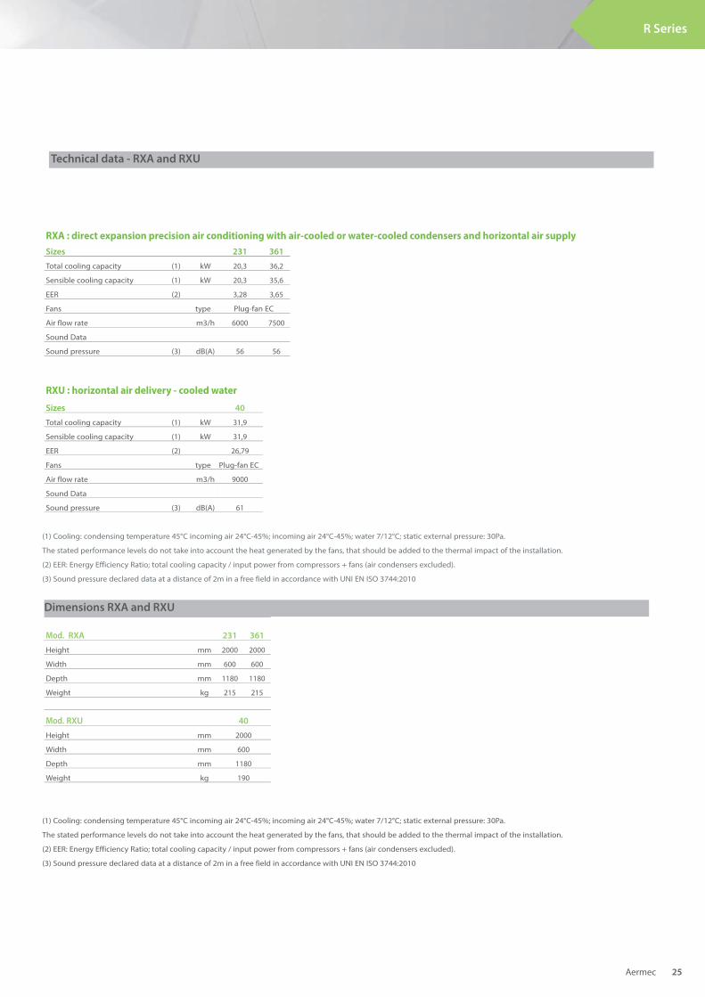
Technical data - RXA and RXU
Aermec 25
R Series
RXA : direct expansion precision air conditioning with air-cooled or water-cooled condensers and horizontal air supply
Sizes 231 361
Total cooling capacity (1) kW 20,3 36,2
Sensible cooling capacity (1) kW 20,3 35,6
EER (2) 3,28 3,65
Fans type Plug-fan EC
Air flow rate m3/h 6000 7500
Sound Data
Sound pressure (3) dB(A) 56 56
RXU : horizontal air delivery - cooled water
Sizes 40
Total cooling capacity (1) kW 31,9
Sensible cooling capacity (1) kW 31,9
EER (2) 26,79
Fans type Plug-fan EC
Air flow rate m3/h 9000
Sound Data
Sound pressure (3) dB(A) 61
Mod. RXA 231 361
Height mm 2000 2000
Width mm 600 600
Depth mm 1180 1180
Weight kg 215 215
Mod. RXU 40
Height mm 2000
Width mm 600
Depth mm 1180
Weight kg 190
Dimensions RXA and RXU
(1) Cooling: condensing temperature 45°C incoming air 24°C-45%; incoming air 24°C-45%; water 7/12°C; static external pressure: 30Pa.
The stated performance levels do not take into account the heat generated by the fans, that should be added to the thermal impact of the installation.
(2) EER: Energy Efficiency Ratio; total cooling capacity / input power from compressors + fans (air condensers excluded).
(3) Sound pressure declared data at a distance of 2m in a free field in accordance with UNI EN ISO 3744:2010
Evolving technology has created the necessity for ever greater exchange of data, increasing exponentially the concentration of electronic equipment inside Data Centres. Infrastructure limits and constantly increasing energy costs have therefore redefined the standards of design and development of Data Centres, making efficiency and energy saving the key concepts for the choice of Precision Air Conditioning.In order to better defi ne the abstract concepts, four main indexes have been created:
Achieving high effi ciency Data Centres
Energy effi ciency:terminology
DCiE (Data Centre Infrastructure Efficiency) is the inverse of PUE. It is the percentage value derived by dividing information technology equipment power by total facility power. As with PUE, an increase in DCiE is directly related to the efficiency of the air conditioning plant.
CAPEX (CAPital EXpenditure), is the money used to buy fixed assets of an operational nature i.e. investment in capital assets. CAPEX is found on the cash flow statement and is obtained from the difference of the gross values of the materials capitalized (noted as “Investment in Plant, Property, and Equipment”) in a given year and the preceding one.
OpEx (OPerating EXpenditure) is the cost necessary for running a product, business or a system. The selection of an air conditioning plant with a high degree of efficiency and sustainability - which can optimize its own operation to suit the real requirements of the system thus maximising its efficiency and decreasing its CO2 emissions to a minimum – enables very high OPEX index levels to be achieved.
PUE (Power Usage Effectiveness) is a measure of how efficiently a computer Data Centre uses its electrical energy. It is a parameter which explains how much electrical energy is used by IT equipment compared to other auxiliary services such as air conditioning, lighting or UPS losses. PUE is the ratio of total power used by the Data Centre facility (PT) to the power used only by IT equipment (PIT). A PUE value approaching 1 indicates an optimal level of efficiency. An air conditioning plant with reduced energy consumption and, where possible, advanced energy saving systems such as Free Cooling, dramatically reduces the PUE index.
1/PUE x 100
%
CAPEX – Index of initial investment
OPEX – Index of operating costs
PUE – Index of energy effi ciency
DCiE – Index of IT equipment effi ciency
Aermec 26
High Density
Data Centres
The absolute reliability of AERMEC air conditioners is guaranteed by design processes using computerized thermodynamic modelling, tests carried out in advanced R&D laboratories, the use of latest-generation materials and components, advanced production techniques in a modern facility and a certified Quality System which conforms to ISO 9001 standards.
Thanks to originality, design and attention to the requirements of the market, new solutions for application problems can be found by using AERMEC units in order to:
Energy effi ciency:how it is achieved
The wide range of models and their combined accessories makes it possible to design modular air conditioning plant capable of being fully integrated into the Data Centre. The minimum footprint area of the units and the modulating operation features of the components enables solutions to be tailor-made to fulfil the effective requirements of the infrastructure, as well as guaranteeing the possibility of future expansion without high added costs and increasing the CAPEX index of the Data Centre.
Optimized infrastructure
The constant increase in the amount of electrical power used as a result of the growth of the digital world, has made it necessary to improve the energy efficiency of the plant, in addition to reducing its impact on the environment. The ever-increasing use of renewable energy sources and low energy consumption components make AERMEC units the most competitive choice for Data Centres in particular. The Free Cooling units, EC technology components and software specially designed to reduce power draw together enable savings of over 50% to be made compared to the previous generation of Data Centres.
A fundamental requirement for an increase in the OPEX index of every Data Centre is the guarantee of continuous service and therefore the total reliability of the infrastructure. The combination of our investment in Research and Development, together with the highly reliable main components of the units and the simplified manufacturing processes, make AERMEC Air Precision Conditioners the perfect choice for new-generation Data Centres.
Improve energy effi ciency and sustainability
Reduce operating costs
The first step in obtaining the best possible result with the minimum capital investment is the reassurance that the performance of the equipment used in the infrastructure conforms to the project. AERMEC is therefore proud to present its qualifications in this area:Quality Certification ISO 9001:2000 Vision CE Product CertificationGOST CertificationEUROVENT Certification
Obtain the best results with guaranteed performance
Aermec 27
High Density
Data Centres
The Aermec
solutions
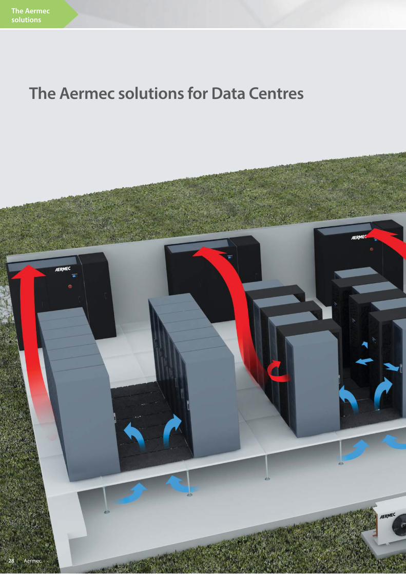
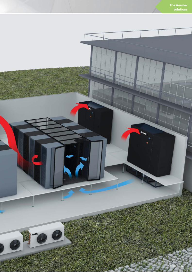
The Aermec solutions for Data Centres
Aermec 28
The Aermec
solutions
Aermec 29


Aermec S.p.A.
Via Roma, 99637040 Bevilacqua (VR) - ItaliaTel. + 39 0442 633111Fax +39 0442 [email protected]
All specifi cations are subject to change without prior notice. Although every eff ort has been made to ensure accuracy, Aermec does not assume responsibility or liability
for eventual errors or omissions.