precast concrete light rail system provides mass transit ... · use a slow and inconvenient bus...
TRANSCRIPT
John F. Kennedy International Airport in Queens,New York, is one of the world’s busiest hubs, avital facility where travelers might expect to findstate-of-the-art surface transportation systems.Prior to 2003, however, travel to and from thevarious airport terminals and parking areasrequired curb-access bus transportation that wasoften inconvenient and slow. After years of failedattempts to rectify the situation, a rapid transit planemerged that successfully solved right-of-way,environmental, and public opinion obstacles. Thenew 8.2 mile (13.2 km) light rail line was built at acost of $1.9 billion under a design-build-operatecontract using a consortium of design andconstruction firms. The light rail system comprisesover 5400 precast concrete segments. One of thegreatest accomplishments of the project was therapid truss erection of precast concrete girderswithin a narrow 10 ft (3.0 m) median with minimaldisruption to major roadway traffic on either side.
Travelers to one of the world’s busiest internationalairports might expect to find a sophisticated and user-friendly transportation system. At New York’s JFK
International Airport, however, inter-terminal transport wascommonly and politely described as a major challenge. Inthe past, access to any of the airport’s six terminals, parkinglots, or ground transportation services required travelers touse a slow and inconvenient bus system at terminal curb-sides. In addition, highways leading to the airport were
Precast Concrete Light RailSystem Provides Mass TransitSolution for JFK International Airport
32 PCI JOURNAL
José M. Rodriguez, P.E.Senior Project DirectorFigg Engineering GroupTallahassee, Florida
Majid Hedayati, P.E. Vice President and Project Director
STV IncorporatedNew York, New York
Antonio Taddeo, P.E. Senior EstimatorKoch Skanska CorporationCarteret, New Jersey
Jennifer K. ParksProject Manager
Bayshore Concrete ProductsCorporation
Cape Charles, Virginia
COVER FEATURE
severely congested – a situation thatcaused a negative impact on airportusage for years. As a result, NewYorkers and international travelersoften turned to other regional airportsfor their transportation needs.
Over the past 35 years, more than20 proposals had been submitted forcreating an efficient transit system thatcould link JFK International Airport toexisting public transportation. All ofthese plans were rejected for variousreasons, including insufficient fund-ing, legal hurdles, or problematic con-nections to existing modes of trans-portation. Finally, in 1996, the PortAuthority of New York & New Jerseyauthorized a proposal that successfullyaddressed the airport’s transit needswith a community-supported plan thatboth optimized existing infrastructureand minimized environmental impact.
PROJECT DESCRIPTIONIn April 1998, the Port Authority
awarded a $1.9 billion design-build-operate-maintain (DBOM) contract tothe AirRail Transit Consortium(ARTC), a strategic joint venture be-tween the AirRail Construction JointVenture (Slattery Skanska, KochSkanska, Sardoni Skanska, and PeriniCorporation) and Bombardier Trans-portation. The Construction Joint Ven-ture (JV) retained STV Incorporatedas the design engineer and Figg Engi-neering Group as consultant for theprecast concrete segmental construc-tion. Bayshore Concrete Products Cor-poration of Cape Charles, Virginia,was contracted to fabricate the precastconcrete segments.
The JFK Light Rail System (Air-Train) links ten airport stations withfast and dependable service to themass transit system of New York City.Two examples reveal the significanceof this transit project. Prior to con-struction of the light rail system, a tripfrom Midtown Manhattan to JFK ter-minals took two hours or more by au-tomobile; today, passengers on thelight rail system can complete thesame trip in 45 minutes. Further, a tripthat used to take 30 minutes aroundJFK’s central terminal area now takesonly eight minutes.
Completion of the new light rail
January-February 2004 33
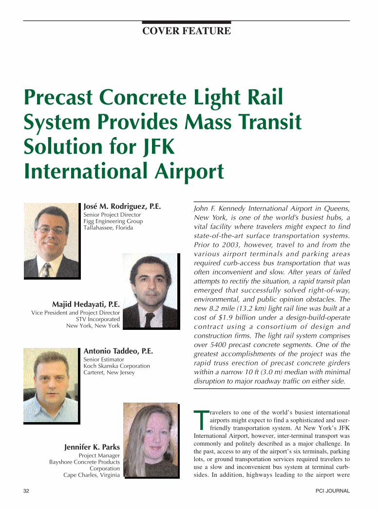
Fig. 1. This night-time photo shows erection of the last precast concrete segment –three months ahead of schedule. Photo courtesy: Figg Engineering Group.
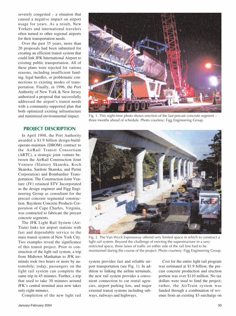
Fig. 2. The Van Wyck Expressway offered very limited space in which to construct alight rail system. Beyond the challenge of erecting the superstructure in a veryrestricted space, three lanes of traffic on either side of the rail line had to bemaintained during the course of the project. Photo courtesy: Figg Engineering Group.
system provides fast and reliable air-port transportation (see Fig. 1). In ad-dition to linking the airline terminals,the new rail system provides a conve-nient connection to car rental agen-cies, airport parking lots, and majorexternal transit systems including sub-ways, railways and highways.
Cost for the entire light rail programwas estimated at $1.9 billion; the pre-cast concrete production and erectionportion was over $110 million. No taxdollars were used to fund the project;rather, the AirTrain system wasfunded through a combination of rev-enue from an existing $3 surcharge on
34 PCI JOURNAL
team and the precast concrete supplierto complete a functional and aestheti-cally pleasing superstructure within a20-month construction timeframe.Productive interaction between the en-gineer, precaster, and contractor keptthe project on a fast-track schedule.The design firm provided two full-time construction engineers on-site toassist the contractor with the erectionprocess. As a result of this close col-laboration, in August 2001 the precastsuperstructure was completed – threemonths ahead of schedule.
DESIGN OF PRECASTCONCRETE ELEVATED
GUIDEWAYThe light rail transit system consists
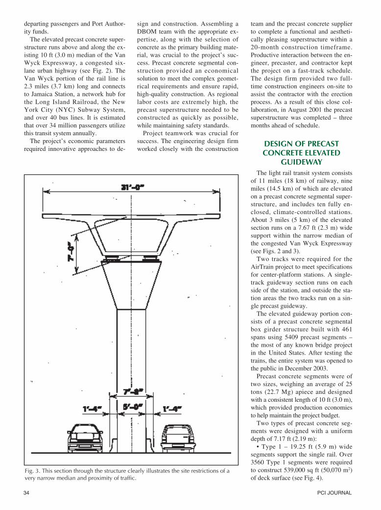
of 11 miles (18 km) of railway, ninemiles (14.5 km) of which are elevatedon a precast concrete segmental super-structure, and includes ten fully en-closed, climate-controlled stations.About 3 miles (5 km) of the elevatedsection runs on a 7.67 ft (2.3 m) widesupport within the narrow median ofthe congested Van Wyck Expressway(see Figs. 2 and 3).
Two tracks were required for theAirTrain project to meet specificationsfor center-platform stations. A single-track guideway section runs on eachside of the station, and outside the sta-tion areas the two tracks run on a sin-gle precast guideway.
The elevated guideway portion con-sists of a precast concrete segmentalbox girder structure built with 461spans using 5409 precast segments –the most of any known bridge projectin the United States. After testing thetrains, the entire system was opened tothe public in December 2003.
Precast concrete segments were oftwo sizes, weighing an average of 25tons (22.7 Mg) apiece and designedwith a consistent length of 10 ft (3.0 m),which provided production economiesto help maintain the project budget.
Two types of precast concrete seg-ments were designed with a uniformdepth of 7.17 ft (2.19 m):
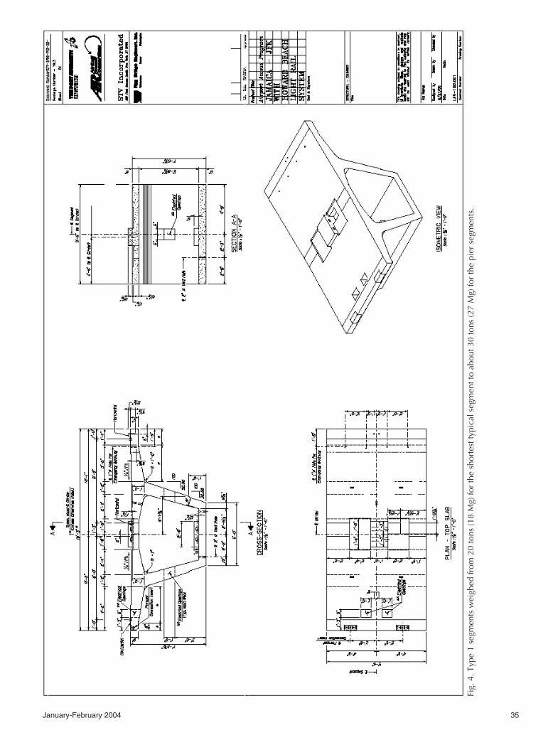
• Type 1 – 19.25 ft (5.9 m) widesegments support the single rail. Over3560 Type 1 segments were requiredto construct 539,000 sq ft (50,070 m2)of deck surface (see Fig. 4).
Fig. 3. This section through the structure clearly illustrates the site restrictions of avery narrow median and proximity of traffic.
departing passengers and Port Author-ity funds.
The elevated precast concrete super-structure runs above and along the ex-isting 10 ft (3.0 m) median of the VanWyck Expressway, a congested six-lane urban highway (see Fig. 2). TheVan Wyck portion of the rail line is2.3 miles (3.7 km) long and connectsto Jamaica Station, a network hub forthe Long Island Railroad, the NewYork City (NYC) Subway System,and over 40 bus lines. It is estimatedthat over 34 million passengers utilizethis transit system annually.
The project’s economic parametersrequired innovative approaches to de-
sign and construction. Assembling aDBOM team with the appropriate ex-pertise, along with the selection ofconcrete as the primary building mate-rial, was crucial to the project’s suc-cess. Precast concrete segmental con-struction provided an economicalsolution to meet the complex geomet-rical requirements and ensure rapid,high-quality construction. As regionallabor costs are extremely high, theprecast superstructure needed to beconstructed as quickly as possible,while maintaining safety standards.
Project teamwork was crucial forsuccess. The engineering design firmworked closely with the construction
January-February 2004 35
Fig.
4. T
ype
1 se
gmen
ts w
eigh
ed fr
om 2
0 to
ns (1
8 M
g) fo
r th
e sh
orte
st ty
pica
l seg
men
t to
abou
t 30
tons
(27
Mg)
for
the
pier
seg
men
ts.
36 PCI JOURNAL
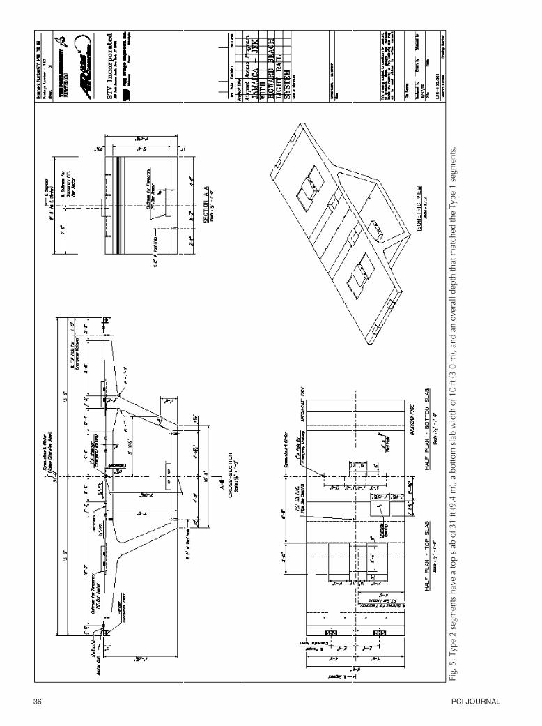
Fig.
5. T
ype
2 se
gmen
ts h
ave
a to
p sl
ab o
f 31
ft (9
.4 m
), a
botto
m s
lab
wid
th o
f 10
ft (3
.0 m
), an
d an
ove
rall
dept
h th
at m
atch
ed th
e Ty
pe 1
seg
men
ts.
January-February 2004 37
• Type 2 – 31 ft (9.4 m) wide seg-ments support the dual rails. Over1840 Type 2 precast segments wererequired to construct 558,000 sq ft(51,840 m2) of deck surface (see Fig.5).
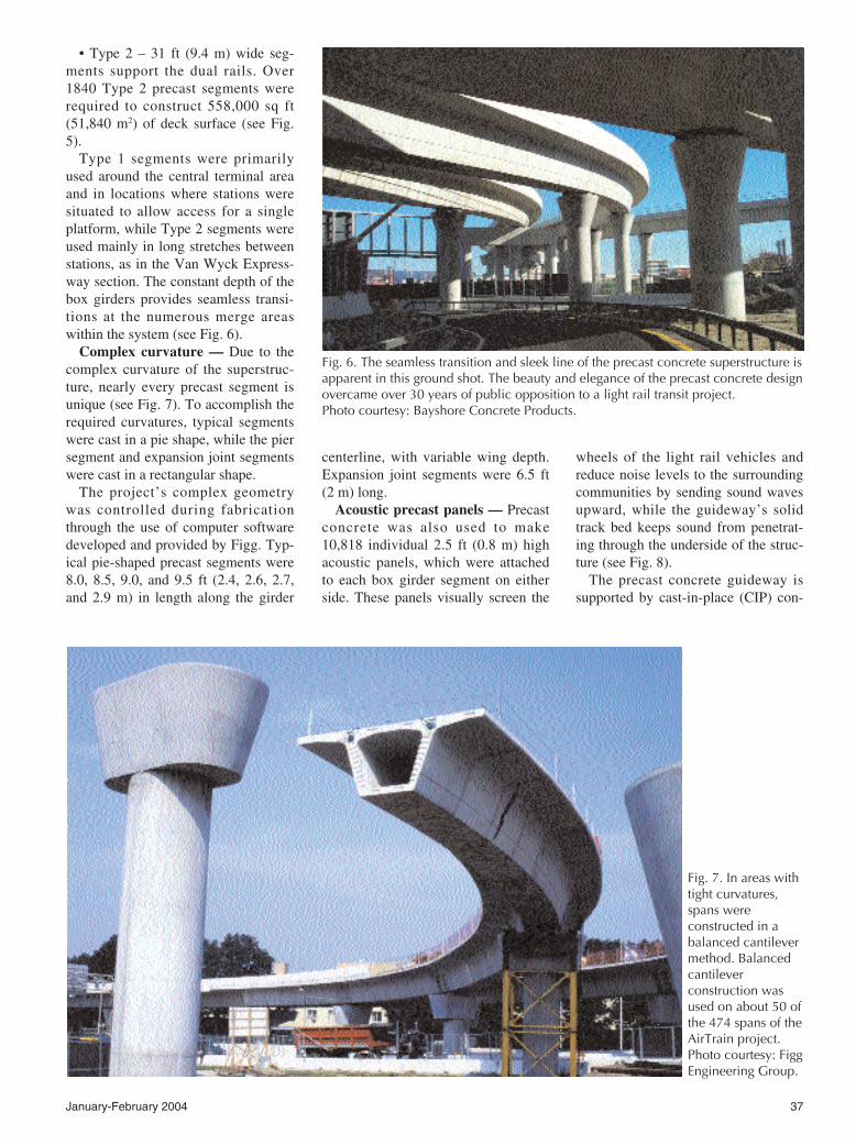
Type 1 segments were primarilyused around the central terminal areaand in locations where stations weresituated to allow access for a singleplatform, while Type 2 segments wereused mainly in long stretches betweenstations, as in the Van Wyck Express-way section. The constant depth of thebox girders provides seamless transi-tions at the numerous merge areaswithin the system (see Fig. 6).
Complex curvature — Due to thecomplex curvature of the superstruc-ture, nearly every precast segment isunique (see Fig. 7). To accomplish therequired curvatures, typical segmentswere cast in a pie shape, while the piersegment and expansion joint segmentswere cast in a rectangular shape.
The project’s complex geometrywas controlled during fabricationthrough the use of computer softwaredeveloped and provided by Figg. Typ-ical pie-shaped precast segments were8.0, 8.5, 9.0, and 9.5 ft (2.4, 2.6, 2.7,and 2.9 m) in length along the girder
centerline, with variable wing depth.Expansion joint segments were 6.5 ft(2 m) long.
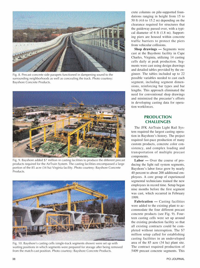
Acoustic precast panels — Precastconcrete was also used to make10,818 individual 2.5 ft (0.8 m) highacoustic panels, which were attachedto each box girder segment on eitherside. These panels visually screen the
wheels of the light rail vehicles andreduce noise levels to the surroundingcommunities by sending sound wavesupward, while the guideway’s solidtrack bed keeps sound from penetrat-ing through the underside of the struc-ture (see Fig. 8).
The precast concrete guideway issupported by cast-in-place (CIP) con-
Fig. 7. In areas withtight curvatures,spans wereconstructed in abalanced cantilevermethod. Balancedcantileverconstruction wasused on about 50 ofthe 474 spans of theAirTrain project. Photo courtesy: FiggEngineering Group.
Fig. 6. The seamless transition and sleek line of the precast concrete superstructure isapparent in this ground shot. The beauty and elegance of the precast concrete designovercame over 30 years of public opposition to a light rail transit project. Photo courtesy: Bayshore Concrete Products.
38 PCI JOURNAL
crete columns on pile-supported foun-dations ranging in height from 15 to50 ft (4.6 to 15.2 m) depending on theclearance required for structures thatthe guideway passed over, with a typi-cal diameter of 6 ft (1.8 m). Support-ing piers are housed within concretetraffic barriers to protect the piersfrom vehicular collisions.
Shop drawings — Segments werecast at the Bayshore facility in CapeCharles, Virginia, utilizing 14 castingcells daily at peak production. Seg-ments were cast using design drawingsand detailed tables provided by the en-gineer. The tables included up to 22possible variables needed to cast eachsegment, including segment dimen-sions, reinforcing bar types and barlengths. This approach eliminated theneed for conventional shop drawingsand minimized the precaster’s effortsin developing casting data for opera-tion workforces.
PRODUCTIONCHALLENGES
The JFK AirTrain Light Rail Sys-tem required the largest casting opera-tion in Bayshore’s history. The projectrequired fast-pace production of manycustom products, concrete color con-sistency, and complex loading andtransportation of multiple precastcomponents.
Labor — Over the course of pro-ducing the light rail system segments,Bayshore’s labor force grew by nearly40 percent to about 200 additional em-ployees. A core group of experiencedsegmental technicians trained the newemployees in record time. Setup begannine months before the first segmentwas cast, which occurred in February1999.
Fabrication — Casting facilitieswere added to the existing plant to ac-commodate the four different precastconcrete products (see Fig. 9). Four-teen casting cells were set up aroundthe existing production facility so thatall existing contracts could be com-pleted without interruption. The $7million setup called for establishingcasting facilities in an undevelopedarea of the 85 acre (34 ha) plant site.The contract required production of5409 precast concrete segments. This
Fig. 10. Bayshore’s casting cells (single-track segments shown) were set up withwaiting positions in which segments were prepared for storage after being removedfrom the match-cast position. Photo courtesy: Bayshore Concrete Products.
Fig. 9. Bayshore added $7 million in casting facilities to produce the different precastproducts required for the AirTrain System. The casting facilities encompassed a largeportion of the 85 acre (34 ha) Virginia facility. Photo courtesy: Bayshore ConcreteProducts.
Fig. 8. Precast concrete side parapets functioned in dampening sound to thesurrounding neighborhoods as well as concealing the track. Photo courtesy:Bayshore Concrete Products.
January-February 2004 39
quantity was the driving force behindthe number of casting cells that had tobe in production in order to meet thefast-track schedule.
In addition to modifying the existingfour-segment casting cells to accom-modate the dual-track typical and de-viator segments, Bayshore constructedsix single-track casting cells for typi-cal and deviator segments, one single-track pier cell, one single-track expan-sion cell, one dual-track pier cell, andone dual-track expansion cell.
Erection Schedule
Segments were cast at a rate of 12per day to meet the erection schedule.In addition to the segmental produc-tion, 15 parapets, 15 walkways, andfive parapet/walkway combinationswere produced daily. From 250 to 300custom precast concrete elementswere produced weekly; over 16,700bridge components were produced intotal (see Fig. 10).
Production began at 4 a.m. with theas-cast survey of the segments. Formswere removed with overhead cranes ortruck cranes. At least two truckloadsof reinforcing steel were consumed indaily production along with largequantities of post-tensioning tendons,deviation pipes, and anchors.
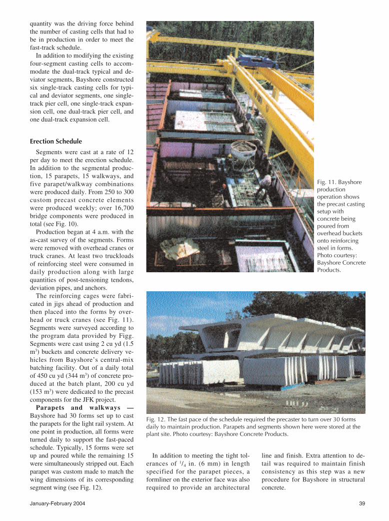
The reinforcing cages were fabri-cated in jigs ahead of production andthen placed into the forms by over-head or truck cranes (see Fig. 11).Segments were surveyed according tothe program data provided by Figg.Segments were cast using 2 cu yd (1.5m3) buckets and concrete delivery ve-hicles from Bayshore’s central-mixbatching facility. Out of a daily totalof 450 cu yd (344 m3) of concrete pro-duced at the batch plant, 200 cu yd(153 m3) were dedicated to the precastcomponents for the JFK project.
Parapets and walkways —Bayshore had 30 forms set up to castthe parapets for the light rail system. Atone point in production, all forms wereturned daily to support the fast-pacedschedule. Typically, 15 forms were setup and poured while the remaining 15were simultaneously stripped out. Eachparapet was custom made to match thewing dimensions of its correspondingsegment wing (see Fig. 12).
In addition to meeting the tight tol-erances of 1/4 in. (6 mm) in lengthspecified for the parapet pieces, aformliner on the exterior face was alsorequired to provide an architectural
line and finish. Extra attention to de-tail was required to maintain finishconsistency as this step was a newprocedure for Bayshore in structuralconcrete.
Fig. 12. The fast pace of the schedule required the precaster to turn over 30 formsdaily to maintain production. Parapets and segments shown here were stored at theplant site. Photo courtesy: Bayshore Concrete Products.
Fig. 11. Bayshoreproductionoperation showsthe precast castingsetup withconcrete beingpoured fromoverhead bucketsonto reinforcingsteel in forms.Photo courtesy:Bayshore ConcreteProducts.
40 PCI JOURNAL
Three types of walkways were cast.Single-track walkways were designedto support a grating, the dual-trackwalkways were flat, and the para-pet/walkway combinations were usedin rail transition areas. As with theparapet production, 15 forms werecast daily while the remaining 15forms were stripped and prepared forpouring the next day. Five combina-tion forms were set up and cast daily.
Color Consistency
Segment color was a critical issuefor the owner. The color of the seg-
mental precast pieces had to matchthat of the CIP concrete substructureportions of the light rail and the sur-rounding structures. Much effort wastaken in the design of the concretemixture and control of its subsequentset color to ensure that all elements ofthe precast superstructure blended to-gether at each location.
The precast products were cast withtwo different sand types – white grayand mesa beige (typical) – to allow forcolor changes from one line to thenext. As a result, two separate con-crete mix designs were necessary, re-quiring a significant investment by the
precaster to ensure quality control forthe non-typical fine aggregates.
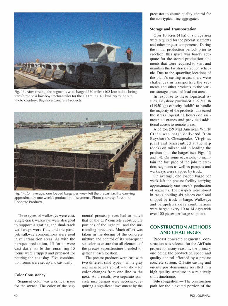
Storage and Transportation
Over 10 acres (4 ha) of storage areawere required for the precast segmentsand other project components. Duringthe initial production periods prior toerection, this space was barely ade-quate for the stored production ele-ments that were required to start andmaintain the fast-track erection sched-ule. Due to the sprawling locations ofthe plant’s casting areas, there werechallenges in transporting the seg-ments and other products to the vari-ous storage areas and load-out areas.
In response to these logistical is-sues, Bayshore purchased a 92,500 lb(41950 kg) capacity forklift to handlethe majority of the products; this easedthe stress (operating hours) on rail-mounted cranes and provided addi-tional access to remote areas.
A 65 ton (59 Mg) American WhirlyCrane was barge-delivered fromBayshore’s Chesapeake, Virginia,plant and reassembled at the slip(dock) on rails to aid in loading theproduct onto the barges (see Figs. 13and 14). On some occasions, to main-tain the fast pace of the jobsite erec-tion, segments as well as parapets andwalkways were shipped by truck.
On average, one loaded barge perweek left the precast facility carryingapproximately one week’s productionof segments. The parapets were storedin racks holding six pieces each andshipped by truck or barge. Walkwaysand parapet/walkway combinationswere barged every 10 to 14 days withover 100 pieces per barge shipment.
CONSTRUCTION METHODSAND CHALLENGES
Precast concrete segmental con-struction was selected for the AirTrainproject for many reasons, the primaryone being the production speed andquality control afforded by a precastconcrete system. Off-site casting andon-site post-tensioning resulted in ahigh quality structure in a relativelyshort timeframe.
Site congestion — The constructionpath for the elevated portion of the
Fig. 14. On average, one loaded barge per week left the precast facility carryingapproximately one week’s production of segments. Photo courtesy: BayshoreConcrete Products.
Fig. 13. After casting, the segments were barged 250 miles (402 km) before beingtransferred to a low-boy tractor-trailer for the 100 mile (161 km) trip to the site. Photo courtesy: Bayshore Concrete Products.
January-February 2004 41
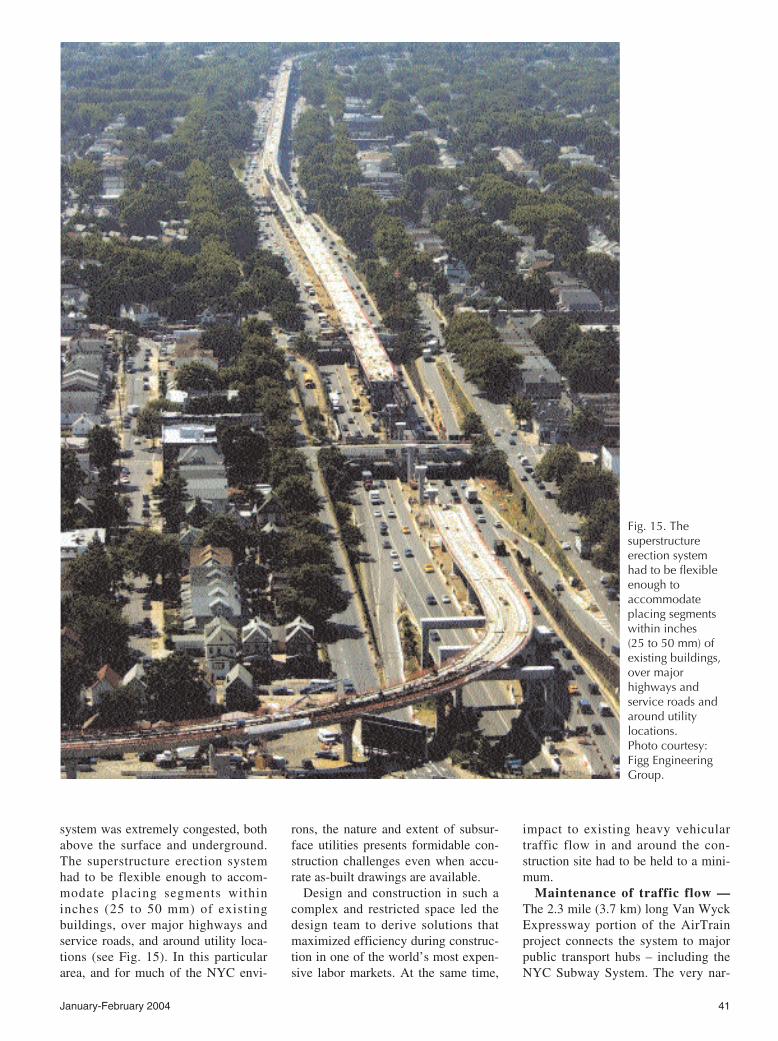
system was extremely congested, bothabove the surface and underground.The superstructure erection systemhad to be flexible enough to accom-modate placing segments withininches (25 to 50 mm) of existingbuildings, over major highways andservice roads, and around utility loca-tions (see Fig. 15). In this particulararea, and for much of the NYC envi-
rons, the nature and extent of subsur-face utilities presents formidable con-struction challenges even when accu-rate as-built drawings are available.
Design and construction in such acomplex and restricted space led thedesign team to derive solutions thatmaximized efficiency during construc-tion in one of the world’s most expen-sive labor markets. At the same time,
impact to existing heavy vehiculartraffic flow in and around the con-struction site had to be held to a mini-mum.
Maintenance of traffic flow —The 2.3 mile (3.7 km) long Van WyckExpressway portion of the AirTrainproject connects the system to majorpublic transport hubs – including theNYC Subway System. The very nar-
Fig. 15. Thesuperstructureerection systemhad to be flexibleenough toaccommodateplacing segmentswithin inches (25 to 50 mm) ofexisting buildings,over majorhighways andservice roads andaround utilitylocations. Photo courtesy:Figg EngineeringGroup.
42 PCI JOURNAL
row median of the Van Wyck Ex-pressway abutting a heavily congestedsix-lane roadway was intentionally de-signed to preclude mass transit con-struction. In fact, Robert Moses, mas-termind and architect of much ofpresent-day New York City infrastruc-ture, actually restricted potential masstransit development by minimizing theamount of right-of-way acquired whenthe expressway was originallyplanned.
Maintenance of traffic flow on theexpressway, a critical transportationconcern, was solved with a bit of inge-nuity. The 100-plus dual-track spanswere erected within the median by uti-lizing the existing roadway to main-tain traffic. By converting the 8.5 ft(2.6 m) shoulders to travel lanes, thetwo center lanes could be periodicallyclosed to traffic to create a 26 ft (7.9m) wide construction zone, while stillmaintaining six travel lanes. On occa-sion, roadways were completelyclosed at night to accommodate thelaunching of segments over majorroutes that intersected the expressway.The complicated logistics required tominimize traffic disruptions requiredconcerted planning throughout theproject.
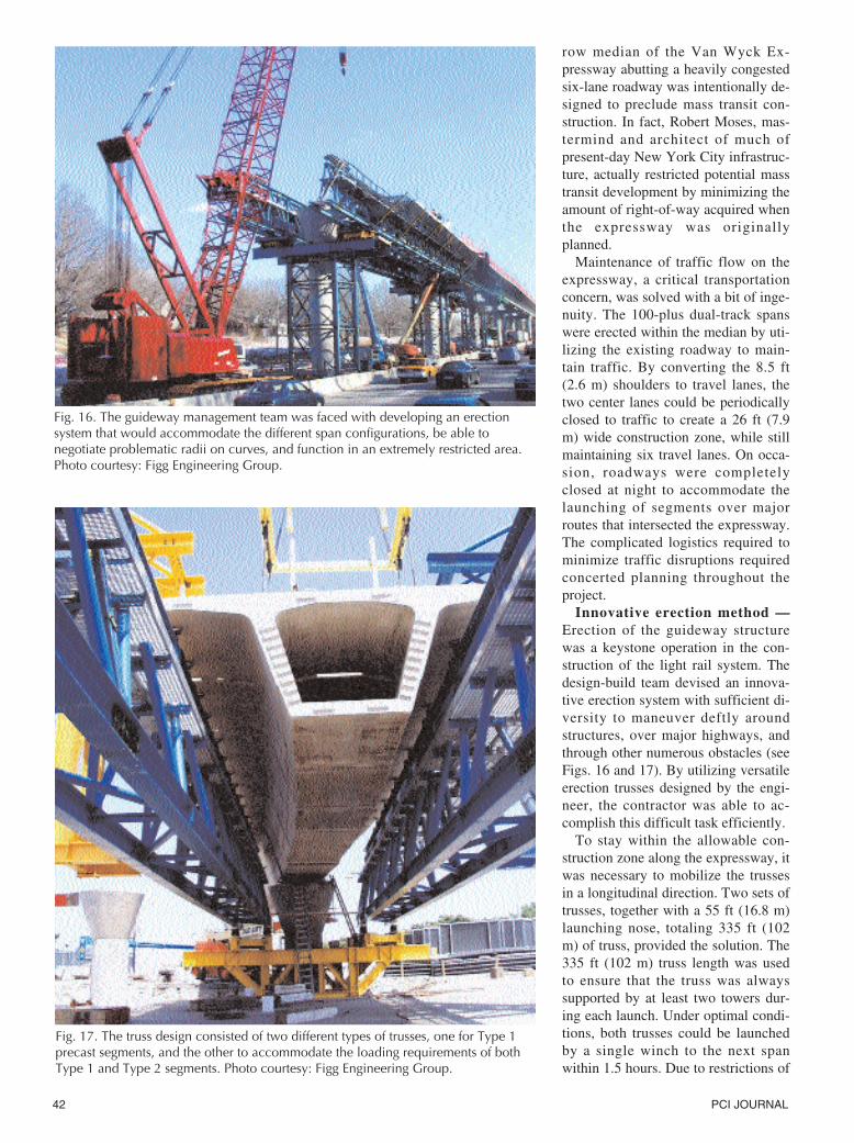
Innovative erection method —Erection of the guideway structurewas a keystone operation in the con-struction of the light rail system. Thedesign-build team devised an innova-tive erection system with sufficient di-versity to maneuver deftly aroundstructures, over major highways, andthrough other numerous obstacles (seeFigs. 16 and 17). By utilizing versatileerection trusses designed by the engi-neer, the contractor was able to ac-complish this difficult task efficiently.
To stay within the allowable con-struction zone along the expressway, itwas necessary to mobilize the trussesin a longitudinal direction. Two sets oftrusses, together with a 55 ft (16.8 m)launching nose, totaling 335 ft (102m) of truss, provided the solution. The335 ft (102 m) truss length was usedto ensure that the truss was alwayssupported by at least two towers dur-ing each launch. Under optimal condi-tions, both trusses could be launchedby a single winch to the next spanwithin 1.5 hours. Due to restrictions of
Fig. 16. The guideway management team was faced with developing an erectionsystem that would accommodate the different span configurations, be able tonegotiate problematic radii on curves, and function in an extremely restricted area.Photo courtesy: Figg Engineering Group.
Fig. 17. The truss design consisted of two different types of trusses, one for Type 1precast segments, and the other to accommodate the loading requirements of bothType 1 and Type 2 segments. Photo courtesy: Figg Engineering Group.
January-February 2004 43
the upstation pier and the truss itself,the crane had a reach of about 40 ft(12.2 m) to lift the 30 ton (27 Mg)segments into place.
Using a specially designed erectiontruss, a span-by-span constructiontechnique was used to build 90 percentof the 461 spans. A balanced can-tilever sequence was used on the re-mainder. Balanced cantilever con-struction met the requirements of tighthorizontal curvatures with radii assmall as 235 ft (72 m) or where spanlengths were greater than 150 ft (46m) – too long for typical span-by-spanconstruction.
Where span-by-span erection wasemployed, specific stroke heights wereprovided to the ironworkers to posi-tion the adjustable jacks supportingthe wings of the segments on the truss.To calculate the stroke heights, trussdeflections, changes to the vertical andhorizontal curves and the variablewing depth data were incorporated toestablish the tower heights. By provid-ing stroke height tolerances to within
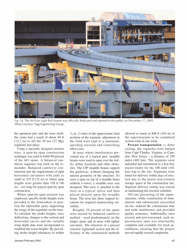
Fig. 18. The AirTrain Light Rail System was officially dedicated and opened to the public on December 17, 2003. Photo courtesy: Figg Engineering Group.
1/8 in. (3 mm) of the approximate finalposition of the segment, adjustment inthe field were kept to a minimum,speeding erection and controllinglabor costs.
In areas where interferences pre-vented use of a typical pier, straddlebeams were used to span over the traf-fic, utility locations and other obsta-cles. The CIP straddle beams supportthe guideway, without changing thenatural geometry of the structure. Toerect a span on top of a straddle beamwithout a tower, a straddle nose wasdesigned. This nose is attached to thetruss at a typical splice and thenplaced directly upon the straddlebeam. The nose has three support lo-cations for required maneuvering ver-satility.
Roughly 10 percent of the spanswere erected by balanced cantilevermethod – used predominately on thelonger spans and in areas with tightercurvature. The selection of a precastconcrete segmental system and the ef-ficiency of the construction methods
allowed as much as 800 ft (244 m) ofthe superstructure to be completedsystem-wide in one week.
Precast transportation — Aftercasting, the segments were bargedfrom Cape Charles, Virginia, to Cam-den, New Jersey – a distance of 250miles (402 km). The segments wereunloaded and transferred to a low-boytractor-trailer for the 100 mile (161km) trip to the site. Segments weretimed for delivery within days of erec-tion due to the nearly non-existentstorage space at the construction site.Segment delivery timing was crucialin maintaining the erection schedule.
Off-site precasting of the super-structure, while construction of foun-dations and substructure proceededon-site, reduced the construction timeand trade interference and providedquality assurance. Additionally, onceerected and post-tensioned, each su-perstructure span was structurallycomplete and available for track in-stallation, ensuring that the projectmoved rapidly toward completion.
44 PCI JOURNAL
Erection of the elevated superstruc-ture was completed in August 2001 –three months ahead of schedule, sav-ing a significant expense. In just 11months, 12,144 linear ft (3700 m) ofguideway superstructure was preciselyerected within the median.
SUMMARY OF PRECAST ADVANTAGES
Overall, selection of a precast con-crete system for the AirTrain projectguaranteed its success and owner sat-isfaction. Precast concrete construc-tion afforded the following crucial ad-vantages in meeting the contractspecifications:
• Elimination of typical shop draw-ings through the use of novel designsoftware significantly reduced seg-ment casting time.
• Maintenance of concrete color con-sistency through precast plant qualitycontrol measures in mixture design,forming, and curing procedures. Theseprocedures minimized staining of theconcrete, eliminated the need for finishcoatings, met strict contract color spec-ifications, and saved construction andmaintenance costs.
• Production efficiencies throughoff-site precast operations and the pre-caster’s ability to meet peak produc-tion quotas for a fast-track schedule.Site congestion was minimized byjust-in-time delivery of precast piecesto the construction site with negligiblestorage space.
• Precast aesthetics for legislativeand community support. Previous ef-forts to construct a light rail system
were effectively blocked by local citi-zens’ opposition to proposals to con-struct unseemly structures that wereperceived to impact negatively onproperty values and standards of liv-ing. The sleekness and beauty of theprecast superstructure design garneredthe vital legislative and communitysupport for the project.
CONCLUDING REMARKSGiven the intricate nature of design-
ing a mass transit system in an ex-tremely congested area at one of theworld’s busiest airports, many com-plex and formidable obstacles facedthe project team. One of the greatestaccomplishments of the guideway’sconstruction was the speed and flaw-lessness at which over 100 dual-trackspans on the expressway section werebuilt, with a minimal disruption to ex-pressway traffic. The use of precastconcrete products, flexible erectionmethods, and the aesthetic appeal ofthe precast design were essential indelivering a maintainable, on-time,and on-budget finished project.
The great success of this projectproves the suitability and adaptabilityof precast concrete segmental con-struction for use in tightly congestedurban corridors. The knowledge, de-sign, and construction techniques de-veloped for the JFK International Air-port Light Rail Transit System willbenefit future mass transit systems inincreasingly congested urban areasworldwide (see Fig. 18).
This project recently won the 2003PCI Design Award for Best Non-
Highway Bridge. In making its selec-tion, the bridge jury commented: “Theprecast method chosen for this projectwas most suitable for the structure.The tight curves were easy to con-struct, and the box girders offer supe-rior structural rigidity and aesthetics.”
CREDITSOwner: Port Authority of New York
& New Jersey, New York, NewYork
Design-Build General Contractor: Air-Rail Construction JV
Engineer of Record: STV Incorpo-rated, New York, New York
Precaster: Bayshore Concrete Prod-ucts, Cape Charles, Virginia
Precast and Superstructure SpecialtyEngineer: Figg Engineering Group,Tallahassee, Florida
Precast Erector: Koch Skanska (Con-struction JV Partner)
Station Construction Manager: Sar-doni Skanska (Construction JV Part-ner)
Substructure, Sitework, and TrackContractor: Slattery Skanska (Con-struction JV Partner)
Post-Tensioning System: DywidagSystems International
Foundations: Muesner Rutledge Con-sulting Engineers
ACKNOWLEDGMENTThe authors would like to extend
their thanks to Anthony G. Cracciolo,Director, Priority Capital Programs,Port Authority of New York & NewJersey, for his valuable assistance.