pre-feasibility report - welcome to...
TRANSCRIPT
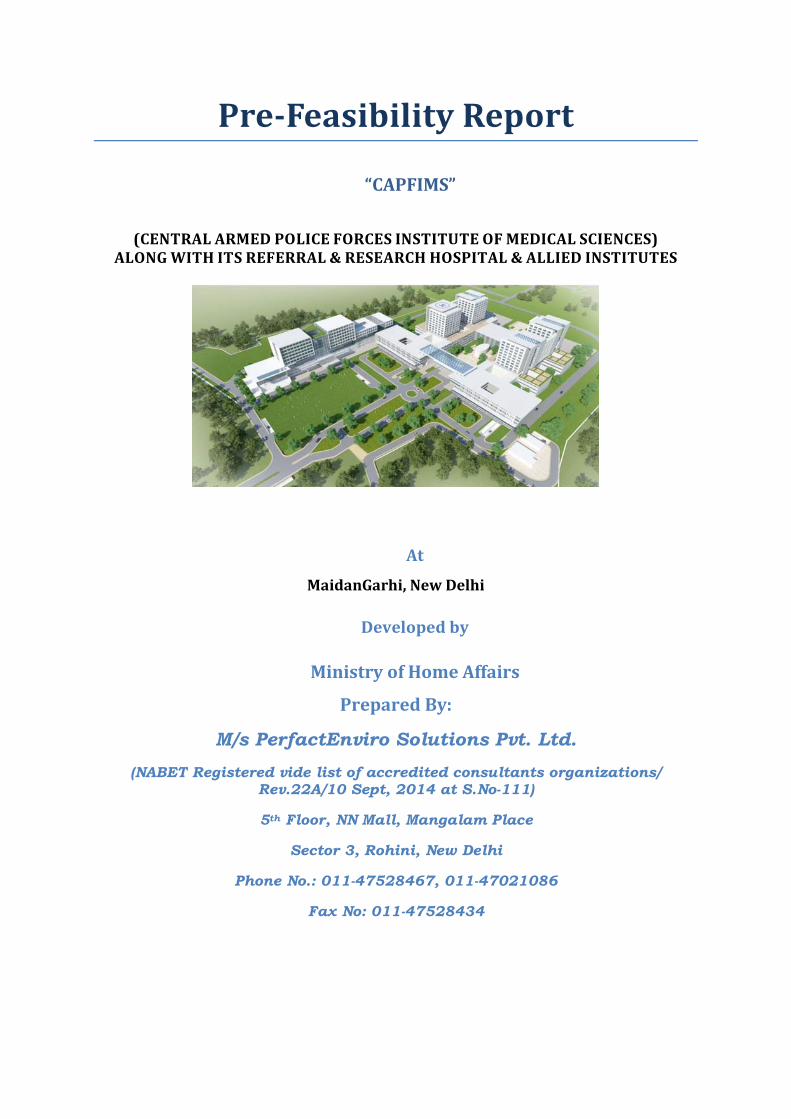
Pre-Feasibility Report
“CAPFIMS”
(CENTRAL ARMED POLICE FORCES INSTITUTE OF MEDICAL SCIENCES)
ALONG WITH ITS REFERRAL & RESEARCH HOSPITAL & ALLIED INSTITUTES
At
MaidanGarhi, New Delhi
Developed by
Prepared By:
M/s PerfactEnviro Solutions Pvt. Ltd. (NABET Registered vide list of accredited consultants organizations/
Rev.22A/10 Sept, 2014 at S.No-111)
5
Ministry of Home Affairs
th Floor, NN Mall, Mangalam Place
Sector 3, Rohini, New Delhi
Phone No.: 011-47528467, 011-47021086
Fax No: 011-47528434
Contents “CAPFIMS” ............................................................................................................................................... 1
At ......................................................................................................................................................... 1
Developed by ...................................................................................................................................... 1
Ministry of Home Affairs ..................................................................................................................... 1
1 EXECUTIVE SUMMARY OF THE PROJECT ........................................................................................ 6
1.1 Activities: ................................................................................................................................. 6
1.2 Description & Details of Project: ............................................................................................. 6
2 INTRODUCTION OF THE PROJECT / BACKGROUND INFORMATION ............................................... 8
2.1 Identification of the Project & Project Proponent: ................................................................. 8
2.2 Brief Description of the Nature of the Project: ....................................................................... 8
2.3 Need for the Project & its Importance to the Country or the region: .................................... 8
2.4 Demand & Supply Gap: ........................................................................................................... 8
2.5 Import vs. Indigenous production: .......................................................................................... 9
2.6 Export Possibilities: ................................................................................................................. 9
2.7 Domestic / Export Markets: .................................................................................................... 9
2.8 Employment Generation (Direct & Indirect) due to the Project: ........................................... 9
3 PROJECT DESCRIPTION .................................................................................................................... 9
3.1 Type of Project including interlinked & interdependent Projects, if any: .............................. 9
3.2 Location (with Coordinates): ................................................................................................... 9
3.2.1 Map showing general location: ..................................................................................... 10
3.2.2 Map showing specific location: ..................................................................................... 11
3.2.3 Map showing Project Boundary: ................................................................................... 11
3.2.4 Map showing Project Site Layout: ................................................................................ 12
3.3 Selection of site ..................................................................................................................... 12
3.3.1 Details of alternate sites considered ............................................................................ 12
3.3.2 Basis for site selection and the environmental considerations .................................... 12
3.4 Size or magnitude of operation ............................................................................................ 12
3.5 Project Description ................................................................................................................ 13
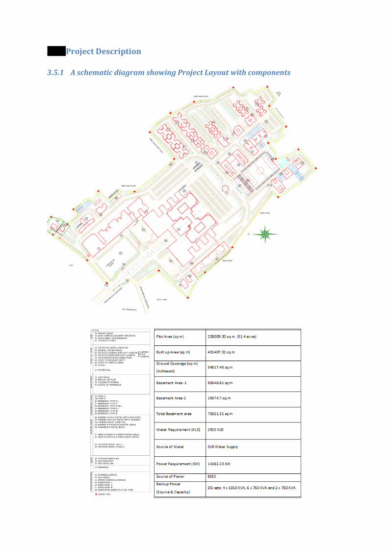
3.5.1 A schematic diagram showing Project Layout with components ................................. 13
3.6 Details of raw material required ........................................................................................... 14
3.6.1 Raw material source and quantity ................................................................................ 14
3.6.2 Marketing area of final products .................................................................................. 14
3.6.3 Mode of transport of raw materials and finished products ......................................... 14
3.7 Resource optimization and reuse and recycling in project resources .................................. 14
3.8 Management of resources .................................................................................................... 15
3.8.1 Water Source and quantity ........................................................................................... 15
3.8.2 Energy source and requirement ................................................................................... 15
3.9 Waste Management ............................................................................................................. 15
3.9.2 Solid waste Management ............................................................................................. 15
3.10 Layout and plans ................................................................................................................... 15
4 SITE ANALYSIS ............................................................................................................................... 16
4.1 Connectivity .......................................................................................................................... 16
4.2 Land form, Land use and land ownership ............................................................................. 16
4.3 Topographical Map ............................................................................................................... 16
4.4 Existing land use pattern ....................................................................................................... 16
4.4.1 Eco-sensitive areas with distance from project location .............................................. 16
4.5 Existing Infrastructure ........................................................................................................... 17
4.6 Soil classification ................................................................................................................... 17
4.7 Climatic data from secondary sources .................................................................................. 17
4.8 Social Infrastructure available .............................................................................................. 20
5 PLANNING BRIEF ........................................................................................................................... 21
5.1 Planning Concept .................................................................................................................. 21
5.2 Population Projection ........................................................................................................... 21
5.3 Land use Planning (break-up along with green belt) ............................................................ 21
5.4 Assessment of Infrastructure Demand (Physical and Social) ................................................ 22

5.5 Amenities/Facilities ............................................................................................................... 22
6 PROPOSED INFRASTRUCTURE ....................................................................................................... 22
6.1 Industrial area ....................................................................................................................... 22
6.2 Residential area ..................................................................................................................... 22
6.3 Green belt and plantation details ......................................................................................... 22
6.3.1 Species to be planted .................................................................................................... 23
6.4 Social Infrastructure .............................................................................................................. 24
6.5 Connectivity .......................................................................................................................... 25
6.6 Drinking water management ................................................................................................ 25
6.6.1 Source and Supply of water .......................................................................................... 25
6.6.2 Water table ................................................................................................................... 27
6.7 Sewerage System .................................................................................................................. 27
6.7.1 Technology details of STP/ ETP with process ................................................................ 27
RE-USE & DISPOSAL OF TREATED EFFLUENT ........................................................................................ 31
6.7.2 Schematic diagram of STP ............................................................................................. 32
6.7.3 Schematic diagram of ETP ............................................................................................. 32
6.7.4 Rain water harvesting ................................................................................................... 33
6.8 Industrial waste management .............................................................................................. 35
6.9 Solid waste management ...................................................................................................... 35
6.10 Power requirement ............................................................................................................... 37
6.10.1 Source ........................................................................................................................... 37
6.10.2 Back-up .......................................................................................................................... 37
7 REHABILITATION AND RESETTLEMENT (R & R ) PLAN .................................................................. 37
7.1 Details on Project Affected person ....................................................................................... 37
8 PROJECT SCHEDULE & COST ESTIMATES ...................................................................................... 37
8.1 Likely date of start of construction and date of completion ................................................ 37
8.2 Estimated project cost .......................................................................................................... 37
9 ANALYSIS OF PROPOSAL ............................................................................................................... 37

9.1 Social benefits to the local population ................................................................................. 37

1 EXECUTIVE SUMMARY OF THE PROJECT
1.1 Activities: There are Residential, Hostel, Mess & Inn, Barracks, Hospital (100 bedded), Nursing college & School
of Paramedics, Hospital (800 bedded, 200 emergency beds). Total no. of blocks will be 7, no of
towers will be 24 and height of the building will be 60 m.
1.2 Description & Details of Project: Sl. No Description Details
1 Proposed Project “CAPFIMS”
(Central Armed Police Institute of Medical sciences)
2. Project Proponent Ministry of Home Affairs.
3. Sr. No of Schedule
(as per Notification 2006) 8 (b)
4 Project Location MaidanGarhi, New Delhi
5 Land Requirement The land is allotted by DDA vide allotment letter no. F.22
(3)10/IL/1429 Dated 27/7/12 for development of hospital.
6 Plot Area (sq m) 2,08,009.30 sq m (51.4 acres)
7 Built up Area (sq m) 4,31,407.31 sq m
8 Ground Coverage (sq m)
(Achieved) 34,817.45 sq m
9 Basement Area -1 56,546.61 sq m
10 Basement Area-2 19,374.7 sq m
11 Total Basement area 75,921.31 sq m
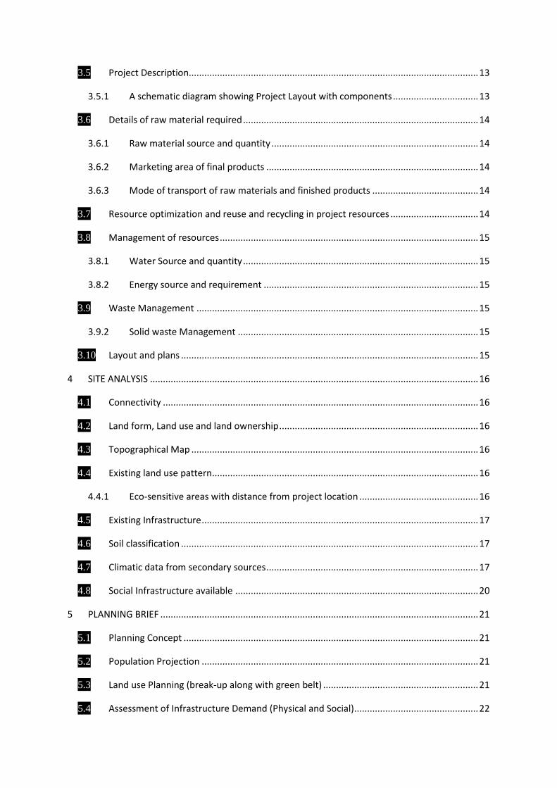
12 Water Requirement (KLD) 2,502 KLD
13 Source of Water Delhi Jal Board Water Supply
14 Power Requirement (KW) 14,162.23 KW
15 Source of Power BSES
16 Backup Power
(Source & Capacity) DG sets: 4 x 10¹⁰ KVA, 6 x 750 KVA and 2 x 750 KVA
17 No. of Rain water
harvesting pits 51
18 Parking Required 6,783 ECS
19 Parking Provision 7,076 ECS
2 INTRODUCTION OF THE PROJECT / BACKGROUND INFORMATION
2.1 Identification of the Project & Project Proponent: The proposed Central Armed Police Forces Institute of Medical Sciences will be located at
MaidanGarhi, New Delhi. The land is allotted By DDA vide allotment letter no. F.22 (3)10/IL/1429
dated 27/7/2012.
2.2 Brief Description of the Nature of the Project: The total plot area is ,208,009.30sqm (51.4 acres) out of which 34817.45 sqm shall be utilized as
Ground Coverage. The built-up area of the project is 4,31,407.31sqm hence it falls under the
category 8 (b) of the EIA notification, 2006.
The proposed CAPFIMS hospital will provide medical facility with high standards. It will render
tertiary and specialised treatment to troops and families of forces like CRPF, BSF, CISF, ITBP, SSB,
NSG and Assam Rifles which function under the command of the Union Home Ministry. The hospital
will boast of some of the best medical care infrastructure in the country which is currently deployed
by the AIIMS and R and R of the Army in Delhi. Besides having a multi-speciality hospital, the
CAPFIMS will also have a medical college, two separate institutes of nursing and paramedics, a
residential campus for students and doctors, an air ambulance unit and a 24x7 mobile hospital unit
for the troops.
2.3 Need for the Project & its Importance to the Country or the region:
• It will increase Infrastructure of the area & will provide better life style.
• It will provide emergent medical facilities to Central Armed Police Forces (CAPF) personnel
• It will provide healthy, green & safe premises.
• It will provide Quality Medical Education to the medical students.
2.4 Demand & Supply Gap: In this fast moving world, the need for good doctor is as necessary as air and water for survival. The
demand for world class Multi-specialty hospital is ever growing.
At present, paramilitary forces do not have a dedicated and regular stream of doctors for their
troops in combat and at far flung locations but with the creation of this infrastructure they will have
doctors in every unit as prevalent in the armed forces like Army, Navy and Air Force.
The CAPFIMS will ensure a dedicated cadre of doctors and paramedical staff for the fighting units
and jawans who are heavily deployed in risk-prone and hard areas for anti-naxal operations,
counter-insurgency operations and border guarding duties.
2.5 Import vs. Indigenous production: As this is a construction of hospital project so this section is not applicable.
2.6 Export Possibilities: As this is a construction of hospital project so this section is not applicable.
2.7 Domestic / Export Markets: As this is a construction of hospital project so this section is not applicable.
2.8 Employment Generation (Direct & Indirect) due to the Project: The Hospital will provide employment to around 150 labourers during construction phase and
employment to 3340 people as staff working in the hospital. Staff will be hired for hospital work,
attendants, mess workers, college staff and other staff for miscellaneous purpose.
3 PROJECT DESCRIPTION
3.1 Type of Project including interlinked & interdependent Projects, if
any: This project is a construction project which comes under category 8 (b) of EIA Notification , 2006 and
it is not an interlinked project.
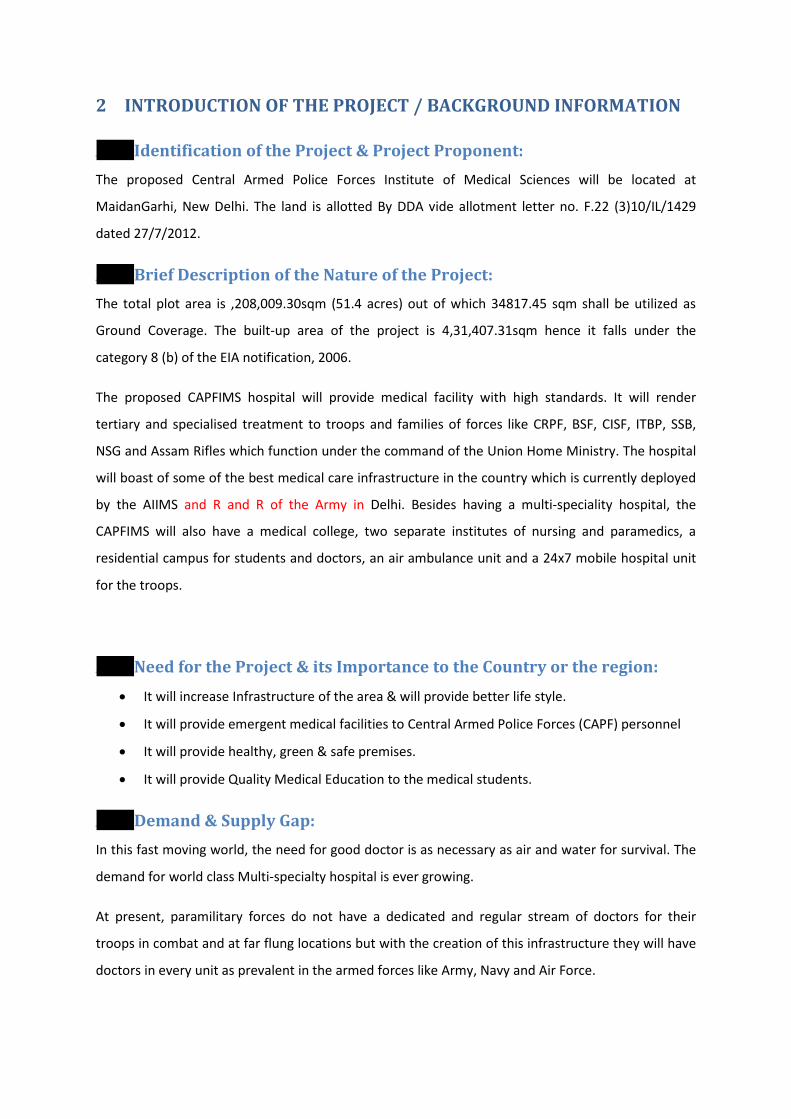
3.2 Location (with Coordinates): Latitude -28°28'28.61"N
Longitude - 77°12'54.83"E
3.2.1 Map showing general location:
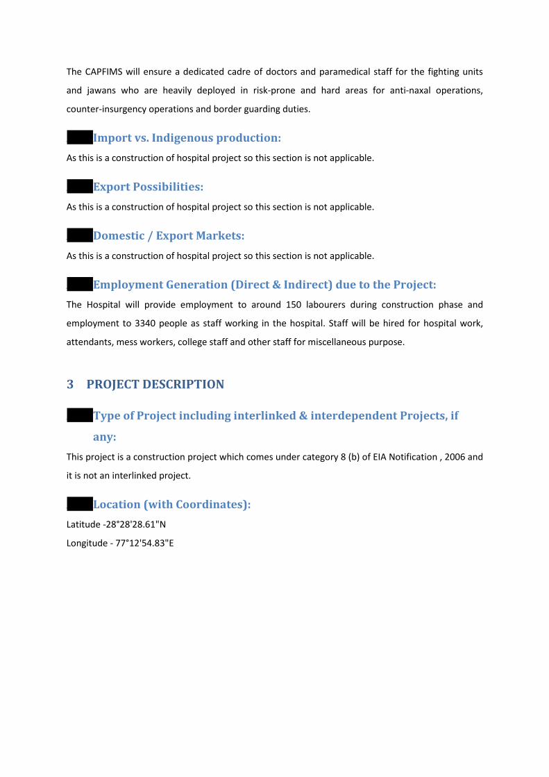
3.2.2 Map showing specific location:
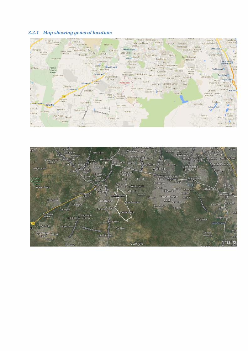
3.2.3 Map showing Project Boundary:
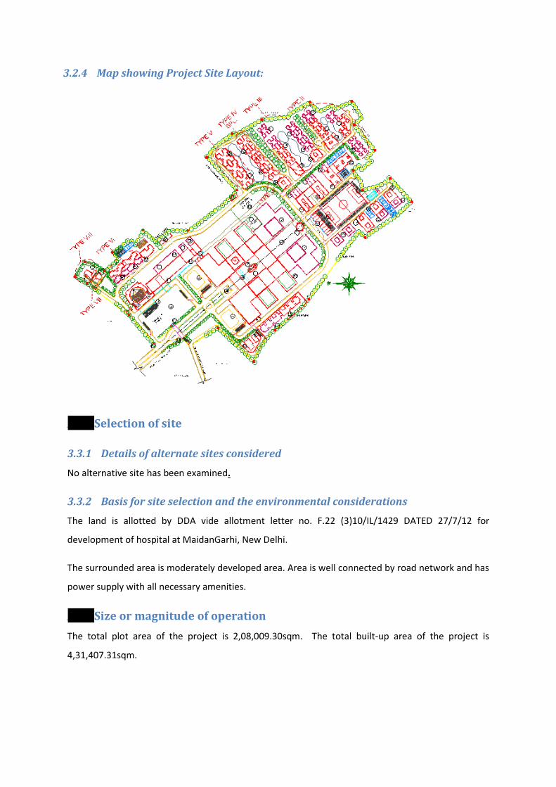
3.2.4 Map showing Project Site Layout:
3.3 Selection of site
3.3.1 Details of alternate sites considered
No alternative site has been examined.
3.3.2 Basis for site selection and the environmental considerations
The land is allotted by DDA vide allotment letter no. F.22 (3)10/IL/1429 DATED 27/7/12 for
development of hospital at MaidanGarhi, New Delhi.
The surrounded area is moderately developed area. Area is well connected by road network and has
power supply with all necessary amenities.
3.4 Size or magnitude of operation The total plot area of the project is 2,08,009.30sqm. The total built-up area of the project is
4,31,407.31sqm.
3.5 Project Description
3.5.1 A schematic diagram showing Project Layout with components
3.6 Details of raw material required
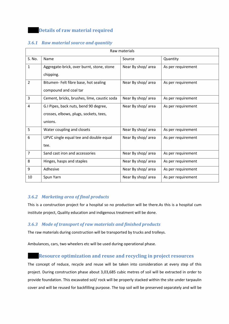
3.6.1 Raw material source and quantity
Raw materials
S. No. Name Source Quantity
1 Aggregate-brick, over burnt, stone, stone
chipping.
Near By shop/ area As per requirement
2 Bitumen- Felt fibre base, hot sealing
compound and coal tar
Near By shop/ area As per requirement
3 Cement, bricks, brushes, lime, caustic soda Near By shop/ area As per requirement
4 G.I Pipes, back nuts, bend 90 degree,
crosses, elbows, plugs, sockets, tees,
unions.
Near By shop/ area As per requirement
5 Water coupling and closets Near By shop/ area As per requirement
6 UPVC single equal tee and double equal
tee.
Near By shop/ area As per requirement
7 Sand cast iron and accessories Near By shop/ area As per requirement
8 Hinges, hasps and staples Near By shop/ area As per requirement
9 Adhesive Near By shop/ area As per requirement
10 Spun Yarn Near By shop/ area As per requirement
3.6.2 Marketing area of final products
This is a construction project for a hospital so no production will be there.As this is a hospital cum
institute project, Quality education and indigenous treatment will be done.
3.6.3 Mode of transport of raw materials and finished products
The raw materials during construction will be transported by trucks and trolleys.
Ambulances, cars, two wheelers etc will be used during operational phase.
3.7 Resource optimization and reuse and recycling in project resources The concept of reduce, recycle and reuse will be taken into consideration at every step of this
project. During construction phase about 3,03,685 cubic metres of soil will be extracted in order to
provide foundation. This excavated soil/ rock will be properly stacked within the site under tarpaulin
cover and will be reused for backfilling purpose. The top soil will be preserved separately and will be
used for landscaping purpose and the excess excavated soil will be disposed off to approve
Municipal Filling Ground.
The treated water from STP will be reused in horticulture, flushing and cooling purpose. The
quantification of the same is given later in Pre-Feasibility report.
The municipal solid waste will be segregated and sent to Organic waste converter. The waste from
Organic waste converter will be used as manure for landscaping.The quantification of the same is
given later in Pre-Feasibility report.
3.8 Management of resources
3.8.1 Water Source and quantity
The total quantity of water required in the project will be 3669 KLD out of which fresh water
requirement will be 940 KLD which will be met by DJB water supply.
3.8.2 Energy source and requirement
The total power requirement will be 14162.3 KW which will be met by BSES.
DG sets of 4 x 10¹⁰ kVA, 6 x 750 KVA and 2 x 500 KVA will be installed for power back-up.
3.9 Waste Management
3.9.1.1 Amount of waste water generated and STP capacity
The amount of waste water generated out of the complex will be 1645KLD. 144 KLD of waste water
from Laboratory will be treated in ETP of 175 KLD and 165 KLD of domestic waste water will be
treatment in STP of 2000 KLD.
3.9.2 Solid waste Management
The amount of municipal waste generated will be 5144 kg/day out of which 3600 kg/day will be
treatedin Organic waste converter and 1544 kg/day will be given to recycler. The hazardous waste in
the form of used oil will be 2 litres/day which will be given to approved vender of CPCB, e –waste of
1 kg/day will be handled as per e-waste management handling rules. The bio-medical waste from
800 beds will be 200 kg/day which will be given to approved biomedical waste service provider.
3.10 Layout and plans • The Layout Plan is attached in Annexure-III
• The topographical Map is attached as Annexure- IV
• The landscape plan is given in Annexure-X
• The parking plan is attached as Annexure-XI
• The dual plumbing plan and drainage plan is given in Annexure-XII
• The plan for sewerage system is given in Annexure XIII
• The external fire hydrant plan is given in Annexure- XIV
• The hospital floor plan is attached as Annexure- XV
• The Typical floor evacuation plan is given in Annexure-XVI
• The basement Plan is given in Annexure-XVII
• The section/elevation is given in Annexure-XVIII
4 SITE ANALYSIS
4.1 Connectivity Site Location:MaidanGarhi, New Delhi
Nearest railway station: Tughlakabad Railway Station : 8.5 Km. E
Nearest airport: Safdarjung Airport : 11.8 Km. N
Nearest National Highway: NH-236 : 5.3 Km NW
4.2 Land form, Land use and land ownership This is a construction of hospital project. The land has been allotted by DDA for development of
hospital vide allotment letter no. F.22(3)10/IL/1429 dated 27/7/2012.
4.3 Topographical Map The Topographical map is attached as Annexure- IV
4.4 Existing land use pattern
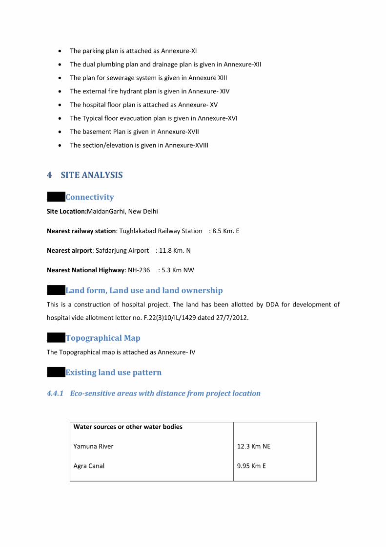
4.4.1 Eco-sensitive areas with distance from project location
Water sources or other water bodies
Yamuna River
Agra Canal
12.3 Km NE
9.95 Km E
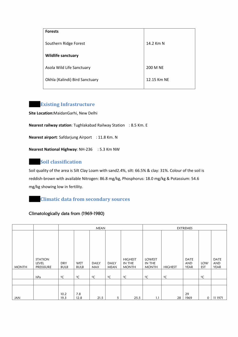
Forests
Southern Ridge Forest
Wildlife sanctuary
Asola Wild Life Sanctuary
Okhla (Kalindi) Bird Sanctuary
14.2 Km N
200 M NE
12.15 Km NE
4.5 Existing Infrastructure Site Location:MaidanGarhi, New Delhi
Nearest railway station: Tughlakabad Railway Station : 8.5 Km. E
Nearest airport: Safdarjung Airport : 11.8 Km. N
Nearest National Highway: NH-236 : 5.3 Km NW
4.6 Soil classification Soil quality of the area is Silt Clay Loam with sand2.4%, silt: 66.5% & clay: 31%. Colour of the soil is
reddish-brown with available Nitrogen: 86.8 mg/kg, Phosphorus: 18.0 mg/kg & Potassium: 54.6
mg/kg showing low in fertility.
4.7 Climatic data from secondary sources
Climatologically data from (1969-1980)
MEAN EXTREMES
MONTH
STATION LEVEL PRESSSURE
DRY BULB
WET BULB
DAILY MAX
DAILY MEAN
HIGHEST IN THE MONTH
LOWEST IN THE MONTH HIGHEST
DATE AND YEAR
LOWEST
DATE AND YEAR
hPa 0C 0C 0C 0C 0C 0C 0 C 0 C
JAN 10.2 19.3
7.8 12.8 21.5 5 25.5 1.1 28
29 1969 0 11 1971
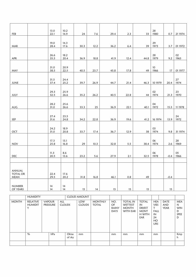
FEB 13.0 22.1
10.2 14.9 24 7.6 29.4 2.3 33
28 1980 0.7 21 1974
MAR 19.0 28.4
14.3 17.6 30.3 12.2 36.2 6.4 39
29 1973 3.7 01 1972
APR 26.6 35.5
18.2 20.4 36.9 18.8 41.9 12.4 44.8
28 1979 9.2
02 1965
MAY 31.0 38.5
20.9 22.5 40.5 23.7 45.8 17.8 49
10 1966 17 01 1977
JUNE 31.5 37.4
24.4 25.2 39.7 26.9 44.7 21.4 46.3 10 1979 20.4
27 1974
JULY 29.3 32.5
25.9 26.6 35.2 26.2 40.5 22.8 44
02 1974 21.3
23 1970
AUG 28.2 31.0
25.6 26.6 33.3 25 36.9 22.1 40.1
04 1972 15.5 11 1978
SEP 27.4 31.6
23.5 24.8 34.2 22.8 36.9 19.6 41.2 16 1974 13.9
24 1972
OCT 24.2 31.0
18.9 20.8 33.7 17.4 36.7 12.9 38
03 1974 9.8 31 1974
NOV 17.3 25.8
13.1 16.8 29 10.3 32.8 5.5 38.4
06 1974 2.6
28 1969
DEC 11.3 20.5
8.6 13.6 23.2 5.6 27.9 2.1 32.5
06 1978 -0.4
05 1966
ANNUAL TOTAL OR MEAN
22.4 29.5
17.6 20.2 31.8 16.8 46.1 0.8 49 -0.4
NUMBER OF YEARS
14 14
14 14 15 14 15 15 15 15
HUMIDITY CLOUD AMOUNT
MONTH RELATIVE HUMIDITY
VAPOUR PRESSURE
ALL CLOUDS
LOW CLOUDS
MONTHLY TOTAL
NO. OF RAINY DAYS
TOTAL IN WETTEST MONTH WITH EAR
TOTAL IN DRIEST MONTH WITH EAR
HEAVIEST FALL IN 24 HOURS
DATE AND YEAR
MEAN WIND SPEED
% hPa Oktas of sky
mm mm mm mm mm Kmph
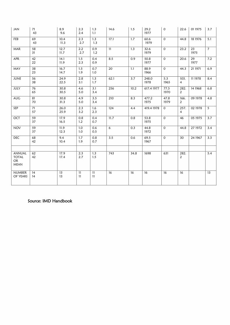
Source: IMD Handbook
JAN 71 43
8.9 9.6
2.3 2.4
1.3 1.1
14.6 1.5 29.2 1977
0 22.6 01 1975 3.7
FEB 69 43
10.4 11.3
2.3 2.7
1.3 1.3
17.1 1.7 60.6 1979
0 44.8 18 1976 5.1
MAR 58 31
12.7 11.7
2.2 2.7
0.9 1.2
11 1.3 32.6 1979
0 23.2 23 1975
7
APR 42 22
14.1 11.9
1.5 2.3
0.4 0.9
8.5 0.9 50.8 1977
0 20.6 29 1977
7.2
MAY 38 23
16.7 14.7
1.5 1.9
0.7 1.0
20 1.1 88.9 1966
0 44.3 21 1971 6.9
JUNE 56 38
24.9 22.5
2.8 3.1
1.3 1.7
62.1 3.7 248.0 1978
5.3 1965
103.4
11 1978 8.4
JULY 76 65
30.8 30.5
4.6 5.0
3.1 3.4
256 10.2 617.4 1977 77.5 1970
282.2
14 1968 6.8
AUG 81 70
30.8 31.3
4.9 5.0
3.5 3.4
210 8.3 477.2 1975
47.8 1979
166.2
09 1978 4.8
SEP 71 57
26.0 25.9
2.3 3.2
1.6 2.3
124 4.4 419.4 1978 0 257.4
02 1978 5
OCT 59 37
17.9 16.5
0.8 1.2
0.4 0.7
11.7 0.8 53.8 1975
0 46 05 1975 3.7
NOV 59 37
11.9 12.3
1.0 1.0
0.6 0.5
6 0.3 44.8 1972
0 44.8 27 1972 3.4
DEC 68 42
9.4 10.4
1.7 1.9
0.8 0.7
3.5 0.6 69.5 1967
0 30 24 1967 3.3
ANNUAL TOTAL OR MEAN
62 42
17.9 17.4
2.3 2.7
1.3 1.5
743 34.8 1698 631 282.2
5.4
NUMBER OF YEARS
14 14
13 13
11 11
11 11
16 16 16 16 16 13
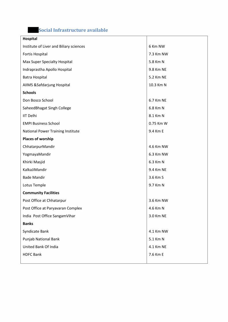
4.8 Social Infrastructure available Hospital
Institute of Liver and Biliary sciences
Fortis Hospital
Max Super Specialty Hospital
Indraprastha Apollo Hospital
Batra Hospital
AIIMS &Safdarjung Hospital
Schools
Don Bosco School
SaheedBhagat Singh College
IIT Delhi
EMPI Business School
National Power Training Institute
Places of worship
ChhatarpurMandir
YogmayaMandir
Khirki Masjid
KalkaJiMandir
Bade Mandir
Lotus Temple
Community Facilities
Post Office at Chhatarpur
Post Office at Paryavaran Complex
India Post Office SangamVihar
Banks
Syndicate Bank
Punjab National Bank
United Bank Of India
HDFC Bank
6 Km NW
7.3 Km NW
5.8 Km N
9.8 Km NE
5.2 Km NE
10.3 Km N
6.7 Km NE
6.8 Km N
8.1 Km N
0.75 Km W
9.4 Km E
4.6 Km NW
6.3 Km NW
6.3 Km N
9.4 Km NE
3.6 Km S
9.7 Km N
3.6 Km NW
4.6 Km N
3.0 Km NE
4.1 Km NW
5.1 Km N
4.1 Km NE
7.6 Km E

5 PLANNING BRIEF
5.1 Planning Concept The proposed Central Armed Police Force Institute of Medical Sciences will be located at
MaidanGarhi, New Delhi. The land is allotted by DDA vide allotment letter no. F.22(3)10/IL/1429
DATED 27/7/12 for development of hospital The total plot area is 2,08,009.30 Sqm (51.4 acres) out
of which 34817.45 Sqmshall be utilized as ground coverage. The built up area of the project is
4,31,407.31sqm as the built up area is greater than 150000 sqm, the project falls under the category
8 (b) of the EIA notification, 2006. The construction has not been started yet. Construction will be
done as per approved Building Plan/ Master Plan.
5.2 Population Projection The total population of the Hospital has been estimated to be 15799, out of which the patients (IPD)
will be 1200, patients (OPD) will be 4000, hospital staff will be 1299, hospital attendants will be
1200, hostel students will be 2296, mess capacity will be 200, barracks residents will be 540, college
staff will be 1140, visitors will be 114, and residential will be 3810.
5.3 Land use Planning (break-up along with green belt)
Plot Area Break Up (Total area =208009.30 sqm)
Ground Coverage (34817.45 sqm)
Road area (113946 sqm)
Green Area ( 59245.88 sqm)
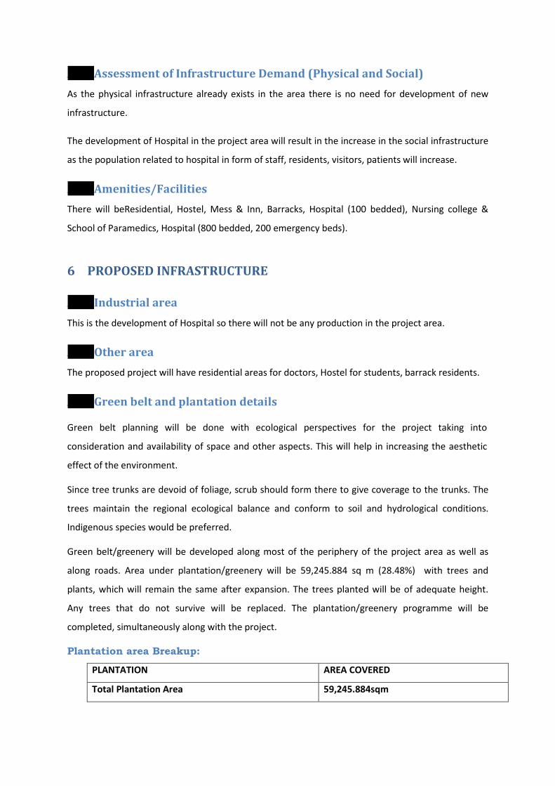
5.4 Assessment of Infrastructure Demand (Physical and Social) As the physical infrastructure already exists in the area there is no need for development of new
infrastructure.
The development of Hospital in the project area will result in the increase in the social infrastructure
as the population related to hospital in form of staff, residents, visitors, patients will increase.
5.5 Amenities/Facilities There will beResidential, Hostel, Mess & Inn, Barracks, Hospital (100 bedded), Nursing college &
School of Paramedics, Hospital (800 bedded, 200 emergency beds).
6 PROPOSED INFRASTRUCTURE
6.1 Industrial area This is the development of Hospital so there will not be any production in the project area.
6.2 Other area The proposed project will have residential areas for doctors, Hostel for students, barrack residents.
6.3 Green belt and plantation details
Green belt planning will be done with ecological perspectives for the project taking into
consideration and availability of space and other aspects. This will help in increasing the aesthetic
effect of the environment.
Since tree trunks are devoid of foliage, scrub should form there to give coverage to the trunks. The
trees maintain the regional ecological balance and conform to soil and hydrological conditions.
Indigenous species would be preferred.
Green belt/greenery will be developed along most of the periphery of the project area as well as
along roads. Area under plantation/greenery will be 59,245.884 sq m (28.48%) with trees and
plants, which will remain the same after expansion. The trees planted will be of adequate height.
Any trees that do not survive will be replaced. The plantation/greenery programme will be
completed, simultaneously along with the project.
Plantation area Breakup:
PLANTATION AREA COVERED
Total Plantation Area 59,245.884sqm
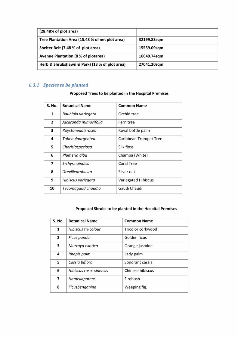
(28.48% of plot area)
Tree Plantation Area (15.48 % of net plot area) 32199.83sqm
Shelter Belt (7.48 % of plot area) 15559.09sqm
Avenue Plantation (8 % of plotarea) 16640.74sqm
Herb & Shrubs(lawn & Park) (13 % of plot area) 27041.20sqm
6.3.1 Species to be planted
Proposed Trees to be planted in the Hospital Premises
S. No. Botanical Name Common Name
1 Bauhinia variegata Orchid tree
2 Jacaranda mimosifolia Fern tree
3 Roystoneaoleracea Royal bottle palm
4 Tabebuiaargentea Caribbean Trumpet Tree
5 Chorisiaspeciosa Silk floss
6 Plumeria alba Champa (White)
7 Erthyrinaindica Coral Tree
8 Grevillearobusta Silver oak
9 Hibiscus variegeta Variegated Hibiscus
10 Tecomagaudichaudia Gaudi Chaudi
Proposed Shrubs to be planted in the Hospital Premises
S. No. Botanical Name Common Name
1 Hibiscus tri-colour Tricolor corkwood
2 Ficus panda Golden ficus
3 Murraya exotica Orange jasmine
4 Rhapis palm Lady palm
5 Cassia biflora Sonorant cassia
6 Hibiscus rosa- sinensis Chinese hibiscus
7 Hameliapatens Firebush
8 Ficusbenganina Weeping fig.

6.4 Social Infrastructure Hospital
Institute of Liver and Biliary sciences
Fortis Hospital
Max Super Specialty Hospital
Indraprastha Apollo Hospital
Batra Hospital
AIIMS &Safdarjung Hospital
Schools
Don Bosco School
SaheedBhagat Singh College
IIT Delhi
EMPI Business School
National Power Training Institute
Places of worship
ChhatarpurMandir
YogmayaMandir
Khirki Masjid
KalkaJiMandir
Bade Mandir
Lotus Temple
Community Facilities
Post Office at Chhatarpur
Post Office at Paryavaran Complex
India Post Office SangamVihar
Syndicate Bank
Punjab National Bank
United Bank Of India
HDFC Bank
6 Km NW
7.3 Km NW
5.8 Km N
9.8 Km NE
5.2 Km NE
10.3 Km N
6.7 Km NE
6.8 Km N
8.1 Km N
0.75 Km W
9.4 Km E
4.6 Km NW
6.3 Km NW
6.3 Km N
9.4 Km NE
3.6 Km S
9.7 Km N
3.6 Km NW
4.6 Km N
3.0 Km NE
4.1 Km NW
5.1 Km N
4.1 Km NE
7.6 Km E
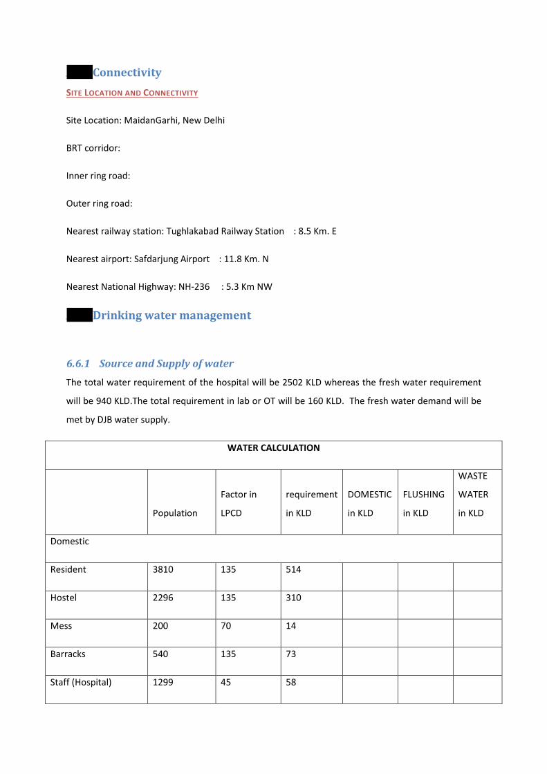
6.5 Connectivity
6.6 Drinking water management
SITE LOCATION AND CONNECTIVITY
Site Location: MaidanGarhi, New Delhi
BRT corridor:
Inner ring road:
Outer ring road:
Nearest railway station: Tughlakabad Railway Station : 8.5 Km. E
Nearest airport: Safdarjung Airport : 11.8 Km. N
Nearest National Highway: NH-236 : 5.3 Km NW
6.6.1 Source and Supply of water
The total water requirement of the hospital will be 2502 KLD whereas the fresh water requirement
will be 940 KLD.The total requirement in lab or OT will be 160 KLD. The fresh water demand will be
met by DJB water supply.
WATER CALCULATION
Population
Factor in
LPCD
requirement
in KLD
DOMESTIC
in KLD
FLUSHING
in KLD
WASTE
WATER
in KLD
Domestic
Resident 3810 135 514
Hostel 2296 135 310
Mess 200 70 14
Barracks 540 135 73
Staff (Hospital) 1299 45 58
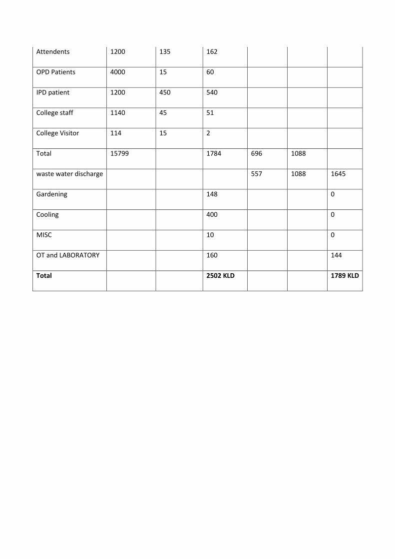
Attendents 1200 135 162
OPD Patients 4000 15 60
IPD patient 1200 450 540
College staff 1140 45 51
College Visitor 114 15 2
Total 15799 1784 696 1088
waste water discharge 557 1088 1645
Gardening 148 0
Cooling 400 0
MISC 10 0
OT and LABORATORY 160 144
Total 2502 KLD 1789 KLD

6.6.2 Water table
6.7 Sewerage System The total waste water generation will be 1789 KLD. The domestic waste water generated of 1645
KLD will be treated in STP of 2000 KLD and treated water will be reused in gardening, flushing and
cooling. The total waste water generation from lab /OT will be 144 KLD which will be treated in ETP
of 175 KLD. Theexcess treated water generated will be discharged in sewer.
6.7.1 Technology details of STP/ ETP with process
Following are the Sewage/Effluent that shall be generated from the entire site:
1) Domestic Sewage from the Toilets &Bathrooms.
2) Medical Waste and Lab Waste
3) Wastewater from Canteen/Cafeteria.
The above mentioned wastes shall be handled as per the following systems:
1) Domestic Sewage from the Toilets &Bathrooms: This shall be collected in the external
sewerage system consisting of pipes and manholes and sent to S.T.P for treatment.

2) Medical Waste and Lab Waste
:This waste shall be treated into the E.T.P of 175 KLD Capacity
Any special medical wastes shall be collected and handled separately as per medical waste
guidelines.
3) Wastewater from Canteen/Cafeteria
: This type of wastes shall also be passed through
Grease traps/Oil separators before its discharging into the S.T.P.
4) It is proposed to treat the complete wastewater as given above shall be treated in a
scientific manner through a properly planned treatment plant. The objective is to stabilize
the decomposable organic matters present in sewage so as to get an effluent and sludge
having characteristics which are within safe limits. To have an efficient treatment system,
this aeration system is proposed consisting of Moving Bed Bio- Reactor Technology(MBBR).
The sewerage treatment plant can be constructed in such a way that it becomes viable by
providing Treated water and sludge that can be used as for mannurefor further use.
Following are the benefits of providing the Sewage Treatment Plant in the present
circumstances:
• It is mandatory as per the latest requirements to provide the Sewage Treatment Plant.
• Reduced net daily fresh water requirements from various sources, by utilizing the
treated water.
• Reduced dependence on the public utilities for water supply and sewerage systems.
• Solid waste generated from the Sewage Treatment Plant shall be rich in organic
materials and is an excellent fertilizer for horticultural purposes.
DIFFERENT COMPONENTS OF THE PLANT
In the proposed treatment scheme the following component unit shall be provided:
Screen /Grit chamber within effluent collection sump.
Equalization tank
Submersible type raw effluent re-lift pumps
MBBR tank
Tube settler
Clarified Water, Filtered Water & Soft Water Storage Tanks
Filter feed pump
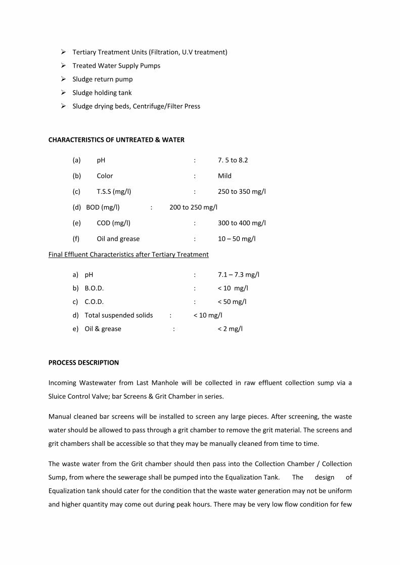
Tertiary Treatment Units (Filtration, U.V treatment)
Treated Water Supply Pumps
Sludge return pump
Sludge holding tank
Sludge drying beds, Centrifuge/Filter Press
CHARACTERISTICS OF UNTREATED & WATER
(a) pH : 7. 5 to 8.2
(b) Color : Mild
(c) T.S.S (mg/l) : 250 to 350 mg/l
(d) BOD (mg/l) : 200 to 250 mg/l
(e) COD (mg/l) : 300 to 400 mg/l
(f) Oil and grease : 10 – 50 mg/l
a) pH : 7.1 – 7.3 mg/l
Final Effluent Characteristics after Tertiary Treatment
b) B.O.D. : < 10 mg/l
c) C.O.D. : < 50 mg/l
d) Total suspended solids : < 10 mg/l
e) Oil & grease : < 2 mg/l
PROCESS DESCRIPTION
Incoming Wastewater from Last Manhole will be collected in raw effluent collection sump via a
Sluice Control Valve; bar Screens & Grit Chamber in series.
Manual cleaned bar screens will be installed to screen any large pieces. After screening, the waste
water should be allowed to pass through a grit chamber to remove the grit material. The screens and
grit chambers shall be accessible so that they may be manually cleaned from time to time.
The waste water from the Grit chamber should then pass into the Collection Chamber / Collection
Sump, from where the sewerage shall be pumped into the Equalization Tank. The design of
Equalization tank should cater for the condition that the waste water generation may not be uniform
and higher quantity may come out during peak hours. There may be very low flow condition for few
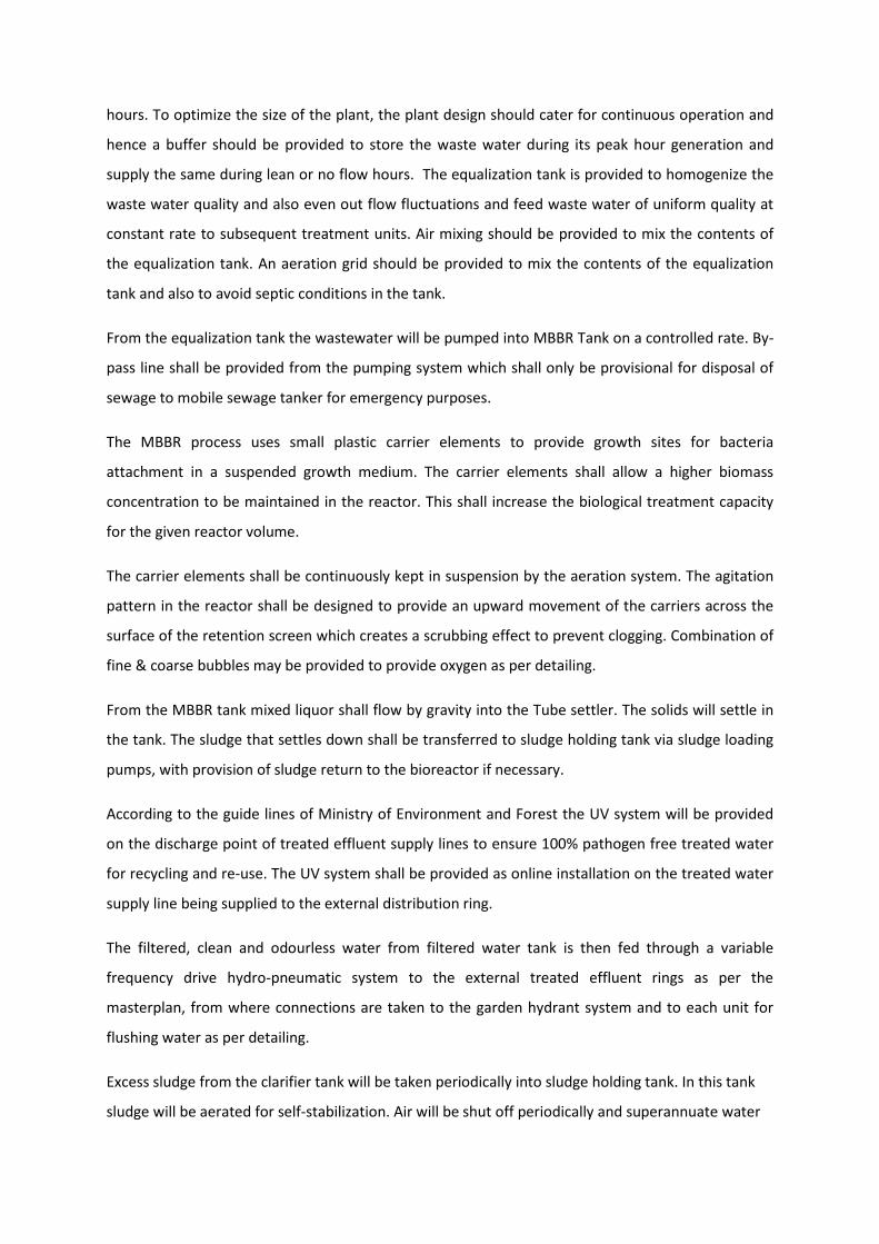
hours. To optimize the size of the plant, the plant design should cater for continuous operation and
hence a buffer should be provided to store the waste water during its peak hour generation and
supply the same during lean or no flow hours. The equalization tank is provided to homogenize the
waste water quality and also even out flow fluctuations and feed waste water of uniform quality at
constant rate to subsequent treatment units. Air mixing should be provided to mix the contents of
the equalization tank. An aeration grid should be provided to mix the contents of the equalization
tank and also to avoid septic conditions in the tank.
From the equalization tank the wastewater will be pumped into MBBR Tank on a controlled rate. By-
pass line shall be provided from the pumping system which shall only be provisional for disposal of
sewage to mobile sewage tanker for emergency purposes.
The MBBR process uses small plastic carrier elements to provide growth sites for bacteria
attachment in a suspended growth medium. The carrier elements shall allow a higher biomass
concentration to be maintained in the reactor. This shall increase the biological treatment capacity
for the given reactor volume.
The carrier elements shall be continuously kept in suspension by the aeration system. The agitation
pattern in the reactor shall be designed to provide an upward movement of the carriers across the
surface of the retention screen which creates a scrubbing effect to prevent clogging. Combination of
fine & coarse bubbles may be provided to provide oxygen as per detailing.
From the MBBR tank mixed liquor shall flow by gravity into the Tube settler. The solids will settle in
the tank. The sludge that settles down shall be transferred to sludge holding tank via sludge loading
pumps, with provision of sludge return to the bioreactor if necessary.
According to the guide lines of Ministry of Environment and Forest the UV system will be provided
on the discharge point of treated effluent supply lines to ensure 100% pathogen free treated water
for recycling and re-use. The UV system shall be provided as online installation on the treated water
supply line being supplied to the external distribution ring.
The filtered, clean and odourless water from filtered water tank is then fed through a variable
frequency drive hydro-pneumatic system to the external treated effluent rings as per the
masterplan, from where connections are taken to the garden hydrant system and to each unit for
flushing water as per detailing.
Excess sludge from the clarifier tank will be taken periodically into sludge holding tank. In this tank
sludge will be aerated for self-stabilization. Air will be shut off periodically and superannuate water
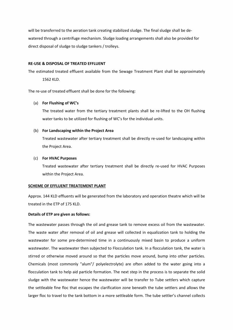
will be transferred to the aeration tank creating stabilized sludge. The final sludge shall be de-
watered through a centrifuge mechanism. Sludge loading arrangements shall also be provided for
direct disposal of sludge to sludge tankers / trolleys.
RE-USE & DISPOSAL OF TREATED EFFLUENT
The estimated treated effluent available from the Sewage Treatment Plant shall be approximately
1562 KLD.
The re-use of treated effluent shall be done for the following:
(a) For Flushing of WC’s
The treated water from the tertiary treatment plants shall be re-lifted to the OH flushing
water tanks to be utilized for flushing of WC’s for the individual units.
(b) For Landscaping within the Project Area
Treated wastewater after tertiary treatment shall be directly re-used for landscaping within
the Project Area.
(c) For HVAC Purposes
Treated wastewater after tertiary treatment shall be directly re-used for HVAC Purposes
within the Project Area.
The wastewater passes through the oil and grease tank to remove excess oil from the wastewater.
The waste water after removal of oil and grease will collected in equalization tank to holding the
wastewater for some pre-determined time in a continuously mixed basin to produce a uniform
wastewater. The wastewater then subjected to Flocculation tank. In a flocculation tank, the water is
stirred or otherwise moved around so that the particles move around, bump into other particles.
Chemicals (most commonly "alum"/ polyelectrolyte) are often added to the water going into a
flocculation tank to help aid particle formation. The next step in the process is to separate the solid
sludge with the wastewater hence the wastewater will be transfer to Tube settlers which capture
the settleable fine floc that escapes the clarification zone beneath the tube settlers and allows the
larger floc to travel to the tank bottom in a more settleable form. The tube settler’s channel collects
SCHEME OF EFFLUENT TREATEMENT PLANT
Approx. 144 KLD effluents will be generated from the laboratory and operation theatre which will be
treated in the ETP of 175 KLD.
Details of ETP are given as follows:
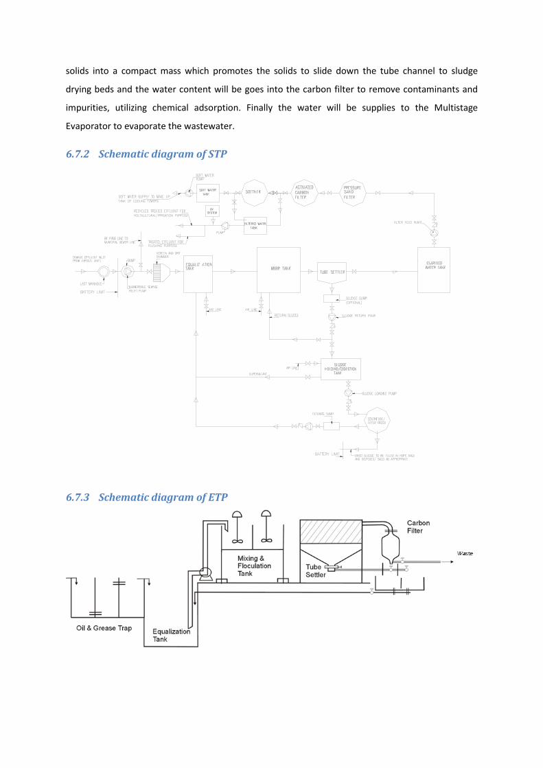
solids into a compact mass which promotes the solids to slide down the tube channel to sludge
drying beds and the water content will be goes into the carbon filter to remove contaminants and
impurities, utilizing chemical adsorption. Finally the water will be supplies to the Multistage
Evaporator to evaporate the wastewater.
6.7.2 Schematic diagram of STP
6.7.3 Schematic diagram of ETP

6.7.4 S.T.P Sludge Generation & Disposal
6.7.5 Rain water harvesting
The main source of ground water recharging in the study area is rainwater, which infiltrates into the
ground through various lithological units present in the study area. 51 nos. of RWH pits are proposed
in the complex site to recharge the ground water. The runoff from the rooftop and storm water shall
go to the recharge pits.
♦ Scheme for Ground Water Recharging
The rainwater will be diverted from the rooftop using rain water pipes to the surface / underground
drainage network. The entire campus will be sub divided for recharging structures. The rainwater
will be diverted into the desilting tank to remove inorganic impurities and the outflow of the
desilting tank is taken into the recharge well.
♦ Desilting Tank
The desilting tanks will be used to remove silt and other floating impurities from rainwater. Desilting
tank is like an ordinary container having provision for the inflow, outflow and overflow. Apart from
removing silt it holds the excess amount of water till it is soaked up by the recharge structure. The
bottom of tank will have unpaved surface (layers of coarse sand) to allow standing water to
percolate into the soil. The rainwater collected in these desilting chambers shall be utilized for
horticulture.
♦ Recharge well
The recharge well consists of percolation pits with boreholes in the middle of the pit. UPVC pipe
perforated will be lowered in the middle of the boreholes and the pit will be filled with gravel and
pebbles in three layers consisting of boulders, gravel and coarse sand. The mouth of the UPVC pipe
shall be protected to avoid silt getting into it. The depth of the bore will depend on the soil
condition/water strata. The schematic diagram is enclosed.
It should be therefore concluded that there is no significant impact on surface water quality &
hydrology of the area. The proposed rainwater-harvesting scheme will stabilize the groundwater
table in the area.
RAIN WATER HARVESTING CALCULATION:-
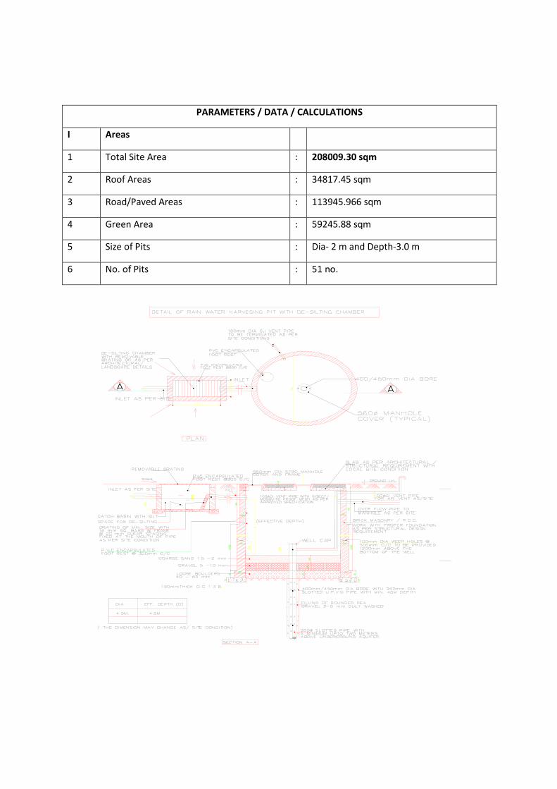
PARAMETERS / DATA / CALCULATIONS
I Areas
1 Total Site Area : 208009.30 sqm
2 Roof Areas : 34817.45 sqm
3 Road/Paved Areas : 113945.966 sqm
4 Green Area : 59245.88 sqm
5 Size of Pits : Dia- 2 m and Depth-3.0 m
6 No. of Pits : 51 no.
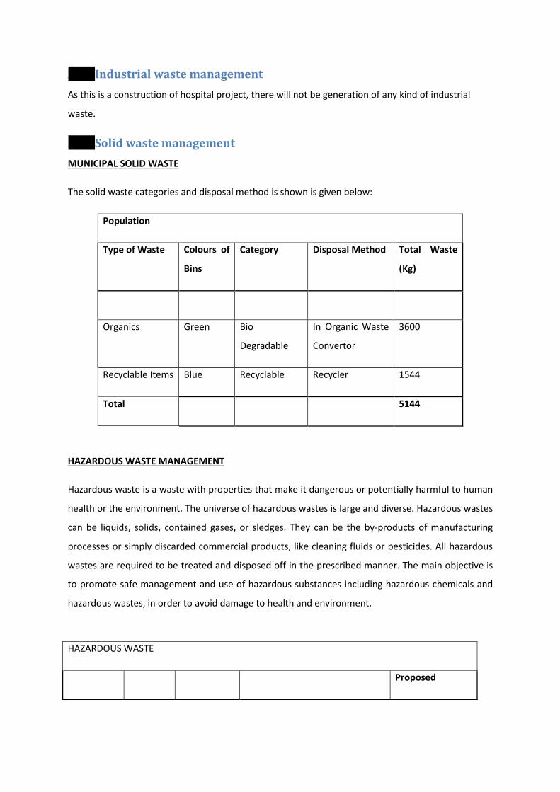
6.8 Industrial waste management As this is a construction of hospital project, there will not be generation of any kind of industrial
waste.
6.9 Solid waste management
Population
MUNICIPAL SOLID WASTE
The solid waste categories and disposal method is shown is given below:
Type of Waste Colours of
Bins
Category Disposal Method Total Waste
(Kg)
Organics Green Bio
Degradable
In Organic Waste
Convertor
3600
Recyclable Items Blue Recyclable Recycler 1544
Total 5144
HAZARDOUS WASTE
HAZARDOUS WASTE MANAGEMENT
Hazardous waste is a waste with properties that make it dangerous or potentially harmful to human
health or the environment. The universe of hazardous wastes is large and diverse. Hazardous wastes
can be liquids, solids, contained gases, or sledges. They can be the by-products of manufacturing
processes or simply discarded commercial products, like cleaning fluids or pesticides. All hazardous
wastes are required to be treated and disposed off in the prescribed manner. The main objective is
to promote safe management and use of hazardous substances including hazardous chemicals and
hazardous wastes, in order to avoid damage to health and environment.
Proposed

BIO-MEDICAL WASTE MANAGEMENT
Type of
Waste
Colours
of Bins Category Disposal Method Total Waste
Used Oil
Black
With
Label
Hazardous
Waste
Waste shall be collected in leak
proof containers at isolated
place and then it will be given to
approved vender of CPCB as per
Hazardous Wastes
(Management/
Handling/Transboundry
Movement) Rules, 2008, as
amended in 2011
2 litres/day
Electronic
Black
With
Label
Hazardous
Waste
E-Waste (Management &
Handling) Rules, 2011 1 kg/day
Bio Medical Waste
Type of Waste No.
of
Beds
Per capita
waste
generation
( gm/bed)
Disposal Method Total quantity of
Biomedical waste
generated
(Kg/day)
Proposed BIO-MEDICAL WASTE 800 250 Approved Biomedical
waste Service Provider
200 Kg/day
6.10 Power requirement
6.10.1 Source
The total electric load of the colony is 14162.23 KW which will be sourced through BSES.
6.10.2 Back-up
In case of power failure, power backup will be provided through DG sets 4 x 10¹⁰, 6 x 750 and 2 x
500 KVA.
7 REHABILITATION AND RESETTLEMENT (R &R ) PLAN
7.1 Details on Project Affected person The land is allotted by DDA vide allotment letter no. F.22 (3)10/IL/1429 dated 27/7/12 for
development of hospital. AS the land is devoid of any habitation and it does not have anybody
staying there at present so the development of this project will not cause or need rehabilitation of
the people.
8 PROJECT SCHEDULE & COST ESTIMATES
8.1 Likely date of start of construction and date of completion Construction shall be started after getting Environmental Clearance and other relevant approvals
and construction will be completed within 42 months.
8.2 Estimated project cost The total estimated cost of the project will be Rs. 1071 crores.
9 ANALYSIS OF PROPOSAL
9.1 Social benefits to the local population It will render tertiary and specialised treatment to troops and families of forces like CRPF, BSF, CISF,
ITBP, SSB, NSG and Assam Rifles which function under the command of the Union Home
Ministry.The hospital will boast of some of the best medical care infrastructure in the country which
is currently deployed by the AIIMS and R and R of the Army in Delhi. Besides having a multi-speciality
hospital, the CAPFIMS will also have a medical college, two separate institutes of nursing and
paramedics, a residential campus for students and doctors, an air ambulance unit and a 24x7 mobile
hospital unit for the troops. The hospitals of the CAPFIMS will also be open for the families of the
force personnel. The paramilitary forces, at present, have a chain of small medical centres and
composite hospitals spread across the country and this will be first comprehensive health care
centre for the sick and injured of these forces on an all-India basis which at present is only available
for the armed forces. The Army's R and R hospital in the national capital is a pioneer in this domain.
Once operational, the hospital and medical college will draw strength and faculty from the existing
medical cadres of these forces and also through direct recruitment. The campus will also have the
facility of an air ambulance and helipad so that injured or sick security personnel could be flown in
from an operational theatre to the CAPFIMS in a helicopter.
The Hospital will provide employment to around 150 labourers during construction phase and
employment to 3340 people as staff working in the hospital. Staff will be hired for hospital work,
attendants, mess workers, college staff and other staff for miscellaneous purpose.