pre-assembled self-regulating cable - king electric · srp pre-assembled self-regulating cable ....
TRANSCRIPT
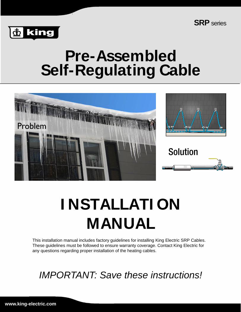
Pre-Assembled Self-Regulating Cable
SRP series
INSTALLATIONMANUAL
IMPORTANT: Save these instructions!
www.king-electric.com
This installation manual includes factory guidelines for installing King Electric SRP Cables. These guidelines must be followed to ensure warranty coverage. Contact King Electric for any questions regarding proper installation of the heating cables.
Solution
SRP Pre-assembled Self-regulating Cable
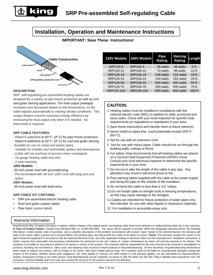
DESCRIPTION:SRP self-regulating pre-assembled heating cables are designed for a variety of pipe freeze protection as well as roof and gutter deicing applications. The heat output (wattage) increases and decreases based on the temperature, so the cable adjusts automatically to varying climate conditions. This unique feature ensures maximum energy efficiency by increasing the heat output only when it is needed. No thermostat is required.
SRP CABLE FEATURES:- Rated 6 watts/foot at 40º F, (4º C) for pipe freeze protection.- Rated 8 watts/foot at 32º F, (0º C) for roof and gutter deicing.-Suitable for use on metal and plastic pipes.- Suitable for metallic and nonmetallic gutters and downspouts.- Cable will not overheat or burnout when overlapped.- 16 gauge heating cable bus wire.- 2 year warranty.120V Models: -30 inch power lead with grounded plug.- Pre-terminated with 30 inch 120V cord with plug and end splice.
240V Models:-30 inch power lead with lead wires
SRP CABLE KIT CONTAINS:• SRP pre-assembled electric heating cable• Roof and gutter caution labels• Pipe trace caution labels
Cable Construction
CAUTION:1. Heating cables must be installed in compliance with the
national electric code (NEC) in addition to state, provincial and local codes. Check with your local inspector for specific code requirements (or regulations or standards) in your area.
2. Save these instructions and transfer them to future owner(s).3. Never install on pipes that could potentially exceed 150º F,
(65º C).4. Not for use with an extension cord.5. Not for use with indoor pipes. Cable should not run through the
building walls, ceilings or floors.6. For safety, King recommends that all heating cables are placed
on a Ground Fault Equipment Protection (GFEP) circuit. Consult your local electrical inspector to determine the specific requirements in your area.
7. Do not cut or alter the length of the cable in any way. Any alteration may result in electrical shock or fire.
8. Post warning labels supplied with the cable at the power supply and along the pipe on the outside of the insulation.
9. Do not bend the cable to less than a 1/2” radius.10.Do not Install cable on shingle roofs in freezing temperatures;
as this may cause damage to the shingles.11.Cables are intended for freeze protection of water pipes only.
Not intended for use with other liquids or hazardous materials.12. For installation in accessible areas only.
Installation, Operation and Maintenance Instructions
King Electrical Mfg. Company will repair or replace, without charge to the original owner, any heating cable found to be defective or malfunctioning within the 2 year warranty.In Case of Product Failure: Contact King Electrical Mfg. Co. at 800.603.5464. The owner will be required to provide, within the designated warranty period, the followinginformation: model number, date of purchase, and a complete description of the problem encountered with product. Upon receipt of the aforementioned, the company willreply to the owner within a period not to exceed fifteen (15) working days, and will provide the action to be taken by owner. Terms: This warranty requires the owner or hisagent install the equipment in accordance with the National Electrical Code, any other applicable heating or electrical codes and the manufacturer's installation instructions. Itfurther requires that reasonable and necessary maintenance be performed on the unit. Failure of proper maintenance by owner will void the warranty in its entirety. Thecompany is not liable for any actions it deems to be abuse or misuse of the product. The customer shall be responsible for all costs incurred in the removal or reinstallation ofproducts, including, but not limited to, labor costs, and shipping costs incurred to return products to King Manufacturing. At their discretion, King Manufacturing will decide toeither repair or replace the product, with no charge to the owner, with return freight paid by King. The Company shall not be liable for consequential damages arising withrespect to the product, whether based upon negligence, tort, strict liability or contract. No other written or oral warranty applies, nor any warranties by Representatives,Dealers, Employees of King or any other person. King Manufacturing can be contacted by phone at 206.762.0400, fax 206.763.7738 or website www.king‐electric.com.Thecompany's minimum liability shall not in any case exceed the list price for the product claimed to be defective.
Warranty Information:
IMPORTANT: Save These Instructions!
Rev 7.31.14www.king-electric.com 2
120V Models 240V Models Pipe Rating
Deicing Rating Length
SRP126-6 SRP246-6 36 watts 48 watts 6 ft.SRP126-12 SRP246-12 72 watts 96 watts 12 ft.SRP126-18 SRP246-18 108 watts 144 watts 18 ft.SRP126-24 SRP246-24 144 watts 192 watts 24 ft.SRP126-50 SRP246-50 300 watts 400 watts 50 ft.SRP126-75 SRP246-75 450 watts 600 watts 75 ft.
SRP126-100 SRP246-100 600 watts 800 watts 100 ft.
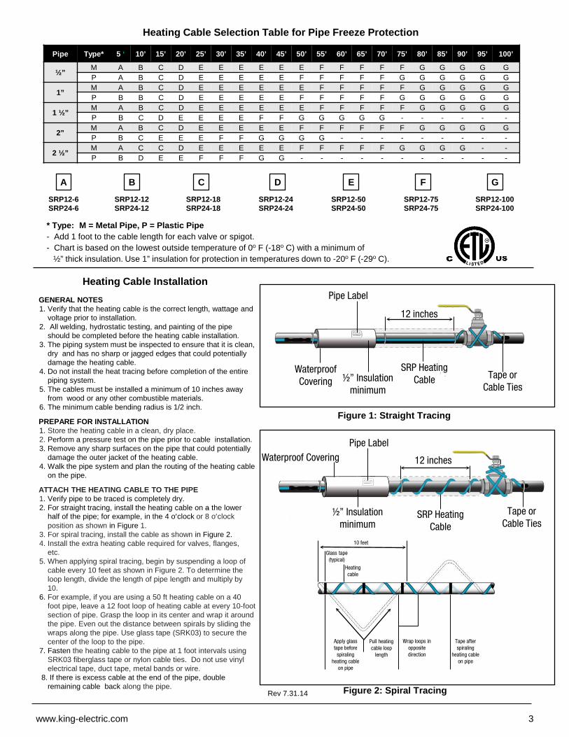
Pipe Type* 5 ‘ 10’ 15’ 20’ 25’ 30’ 35’ 40’ 45’ 50’ 55’ 60’ 65’ 70’ 75’ 80’ 85’ 90’ 95’ 100’
½” M A B C D E E E E E E F F F F F G G G G GP A B C D E E E E E F F F F F G G G G G G
1” M A B C D E E E E E E F F F F F G G G G GP B B C D E E E E E F F F F F G G G G G G
1 ½” M A B C D E E E E E E F F F F F G G G G GP B C D E E E E F F G G G G G - - - - - -
2” M A B C D E E E E E F F F F F F G G G G GP B C E E E F F G G G G - - - - - - - - -
2 ½” M A C C D E E E E E F F F F F G G G G - -P B D E E F F F G G - - - - - - - - - - -
ASRP12-6SRP24-6
B C D E F GSRP12-18SRP24-18
SRP12-24SRP24-24
SRP12-50SRP24-50
SRP12-75SRP24-75
SRP12-100SRP24-100
SRP12-12SRP24-12
Heating Cable Selection Table for Pipe Freeze Protection
* Type: M = Metal Pipe, P = Plastic Pipe- Add 1 foot to the cable length for each valve or spigot.- Chart is based on the lowest outside temperature of 0º F (-18º C) with a minimum of
½” thick insulation. Use 1” insulation for protection in temperatures down to -20º F (-29º C).
GENERAL NOTES1. Verify that the heating cable is the correct length, wattage and
voltage prior to installation.2. All welding, hydrostatic testing, and painting of the pipe
should be completed before the heating cable installation.3. The piping system must be inspected to ensure that it is clean,
dry and has no sharp or jagged edges that could potentially damage the heating cable.
4. Do not install the heat tracing before completion of the entire piping system.
5. The cables must be installed a minimum of 10 inches away from wood or any other combustible materials.
6. The minimum cable bending radius is 1/2 inch.
PREPARE FOR INSTALLATION1. Store the heating cable in a clean, dry place.2. Perform a pressure test on the pipe prior to cable installation.3. Remove any sharp surfaces on the pipe that could potentially
damage the outer jacket of the heating cable. 4. Walk the pipe system and plan the routing of the heating cable
on the pipe.
ATTACH THE HEATING CABLE TO THE PIPE1. Verify pipe to be traced is completely dry.2. For straight tracing, install the heating cable on a the lower
half of the pipe; for example, in the 4 o’clock or 8 o’clock position as shown in Figure 1.
3. For spiral tracing, install the cable as shown in Figure 2. 4. Install the extra heating cable required for valves, flanges,
etc.5. When applying spiral tracing, begin by suspending a loop of
cable every 10 feet as shown in Figure 2. To determine the loop length, divide the length of pipe length and multiply by 10.
6. For example, if you are using a 50 ft heating cable on a 40 foot pipe, leave a 12 foot loop of heating cable at every 10-foot section of pipe. Grasp the loop in its center and wrap it around the pipe. Even out the distance between spirals by sliding the wraps along the pipe. Use glass tape (SRK03) to secure the center of the loop to the pipe.
7. Fasten the heating cable to the pipe at 1 foot intervals using SRK03 fiberglass tape or nylon cable ties. Do not use vinyl electrical tape, duct tape, metal bands or wire.
8. If there is excess cable at the end of the pipe, double remaining cable back along the pipe.
Heating Cable Installation
Figure 1: Straight Tracing
Figure 2: Spiral TracingRev 7.31.14
www.king-electric.com 3
Waterproof Covering
Pipe Label
½” Insulation minimum
SRP Heating Cable Tape or
Cable Ties
12 inches
12 inchesWaterproof CoveringPipe Label
½” Insulation minimum
SRP Heating Cable
Tape or Cable Ties
Apply glass tape before
spiraling heating cable
on pipe
Pull heating cable loop
length
10 feet
Glass tape (typical)
Heating cable
Wrap loops in opposite direction
Tape after spiraling
heating cable on pipe
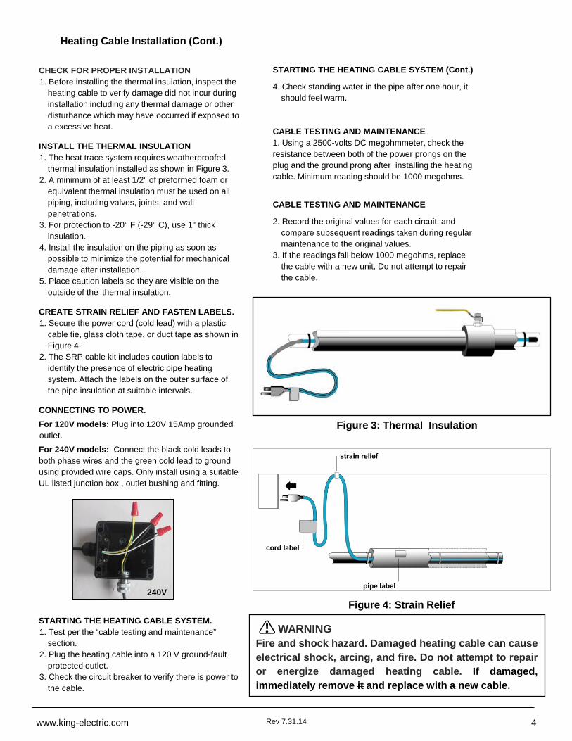
CHECK FOR PROPER INSTALLATION1. Before installing the thermal insulation, inspect the
heating cable to verify damage did not incur during installation including any thermal damage or other disturbance which may have occurred if exposed to a excessive heat.
INSTALL THE THERMAL INSULATION1. The heat trace system requires weatherproofed
thermal insulation installed as shown in Figure 3.2. A minimum of at least 1/2" of preformed foam or
equivalent thermal insulation must be used on all piping, including valves, joints, and wall penetrations.
3. For protection to -20° F (-29° C), use 1" thick insulation.
4. Install the insulation on the piping as soon as possible to minimize the potential for mechanical damage after installation.
5. Place caution labels so they are visible on the outside of the thermal insulation.
CREATE STRAIN RELIEF AND FASTEN LABELS.1. Secure the power cord (cold lead) with a plastic
cable tie, glass cloth tape, or duct tape as shown in Figure 4.
2. The SRP cable kit includes caution labels to identify the presence of electric pipe heating system. Attach the labels on the outer surface of the pipe insulation at suitable intervals.
CONNECTING TO POWER.For 120V models: Plug into 120V 15Amp grounded outlet.For 240V models: Connect the black cold leads to both phase wires and the green cold lead to ground using provided wire caps. Only install using a suitable UL listed junction box , outlet bushing and fitting.
STARTING THE HEATING CABLE SYSTEM.1. Test per the “cable testing and maintenance”
section.2. Plug the heating cable into a 120 V ground-fault
protected outlet.3. Check the circuit breaker to verify there is power to
the cable.
Heating Cable Installation (Cont.)
WARNINGFire and shock hazard. Damaged heating cable can causeelectrical shock, arcing, and fire. Do not attempt to repairor energize damaged heating cable. If damaged,immediately remove it and replace with a new cable.
Figure 3: Thermal Insulation
Figure 4: Strain Relief
Rev 7.31.14www.king-electric.com 4
STARTING THE HEATING CABLE SYSTEM (Cont.)
4. Check standing water in the pipe after one hour, it should feel warm.
CABLE TESTING AND MAINTENANCE1. Using a 2500-volts DC megohmmeter, check the resistance between both of the power prongs on the plug and the ground prong after installing the heating cable. Minimum reading should be 1000 megohms.
CABLE TESTING AND MAINTENANCE
2. Record the original values for each circuit, and compare subsequent readings taken during regular maintenance to the original values.
3. If the readings fall below 1000 megohms, replace the cable with a new unit. Do not attempt to repair the cable.
240V
Use the number in the table and multiply it by the length of the roof edge.
CALCULATIONS FOR GUTTERS, DOWNSPOUT AND VALLEYS:
1. For standard non-metal roofs, add 1 foot of heating cable for each foot of gutter.
2. Add 1 foot of heating cable per foot of downspout.
3. If the downspout is in the middle of the run, loop the cable down and back up. Double the length of the downspout for determining the length of cable to install.
4. For valleys, run the heating cable two thirds of the way up and down the valley. Add this additional length to the overall cable needed.
5. For gutters 6 inches wide use two cable runs.
Selecting the Required Heating Cable Length for Roof and Gutter Deicing
EaveOverhang
StandardRoof
Metal Roof18” Seam
Metal Roof24” Seam
None 2.0 2.5 2.0
12” 2.8 2.8 2.4
24” 3.8 3.6 2.9
36” 4.8 4.3 3.6
Heating Cable Multiplier Table
ELECTRICAL CODESArticle 426 of the National Electrical Code (NEC), and Part 1, Section62 of the Canadian Electrical Code (CEC), govern the installation ofSRP heating cables for roof and gutter deicing and must be followed.
IMPORTANT: For the warranty to be valid, the installer, customer anduser must comply with all the requirements outlined in these guidelines.All design information provided in these instructions are based on a“standard” shake or shingle and metal roof applications. For any otherapplication or method of installation, consult a design specialist.
GENERAL INFORMATION FOR ROOF AND GUTTER DEICING
1. SRP cable is designed to remove ice, not accumulated snow.2. SRP cable will not keep snow or ice from falling off of the roof.
Snow fences or snow guards should be used to eliminate snow movement.
3. SRP heating cables may be used on:- Roofs made from all types of roofing materials, such as
shake, shingle, rubber, tar, wood, metal, and plastic.- Gutters made from standard materials, such as metal
and plastic.- Downspouts made from standard materials, such as metal
and plastic.4.Do not use an extension cord.5. Do not install the heating cable underneath any roof
covering.6. Install only in accessible locations; do not install behind
walls or where the cable would be hidden.7. Do not run the heating cable through walls, ceilings, or floors.8. Connect only to ground-fault protected outlets that have
been installed in accordance with all national and local codes and standards and that are protected from rain and other water sources such as melting ice water.
9. SRP cable is factory preassembled and cannot be altered. Use of any in-line splices or tee-splices will void the warranty. Cut to length cable is available from King, contact your local distributor or visit the King website for information.
10. Do not exceed the amp rating of the over current protection device.
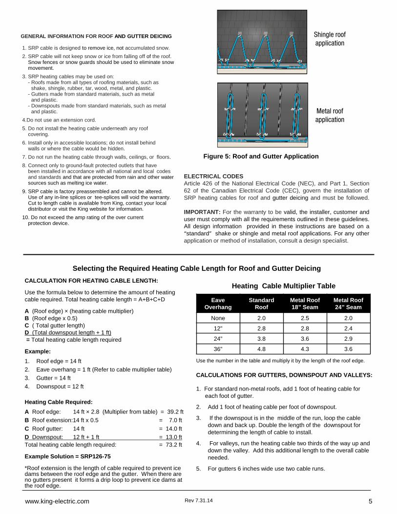
Figure 5: Roof and Gutter Application
CALCULATION FOR HEATING CABLE LENGTH:
Use the formula below to determine the amount of heating cable required. Total heating cable length = A+B+C+D
A (Roof edge) × (heating cable multiplier)B (Roof edge x 0.5)C ( Total gutter length) D (Total downspout length + 1 ft)= Total heating cable length required
Example:1. Roof edge = 14 ft2. Eave overhang = 1 ft (Refer to cable multiplier table)3. Gutter = 14 ft4. Downspout = 12 ft
Heating Cable Required:A Roof edge: 14 ft × 2.8 (Multiplier from table) = 39.2 ftB Roof extension:14 ft x 0.5 = 7.0 ftC Roof gutter: 14 ft = 14.0 ftD Downspout: 12 ft + 1 ft = 13.0 ftTotal heating cable length required: = 73.2 ft
Example Solution = SRP126-75
*Roof extension is the length of cable required to prevent ice dams between the roof edge and the gutter. When there are no gutters present it forms a drip loop to prevent ice dams at the roof edge.
Rev 7.31.14www.king-electric.com 5
Shingle roof application
Metal roof application
PREPARE FOR INSTALLATION1. Store the heating cable in a clean, dry place.2. Inspect for any mechanical damage prior to installation.3. Warranty is void if non-King accessories are used. King approved
accessories include:- SR1K5 Downspout hanger bracket- SRK13 Roof clips
4. Gutters and downspouts must be free of leaves and other debris.5. Plan the routing of the heating cable for roof and gutter deicing.
ATTACH THE HEATING CABLE ON ROOFS1. Loosely loop the heating cable on the roof at the overhang area. Pull
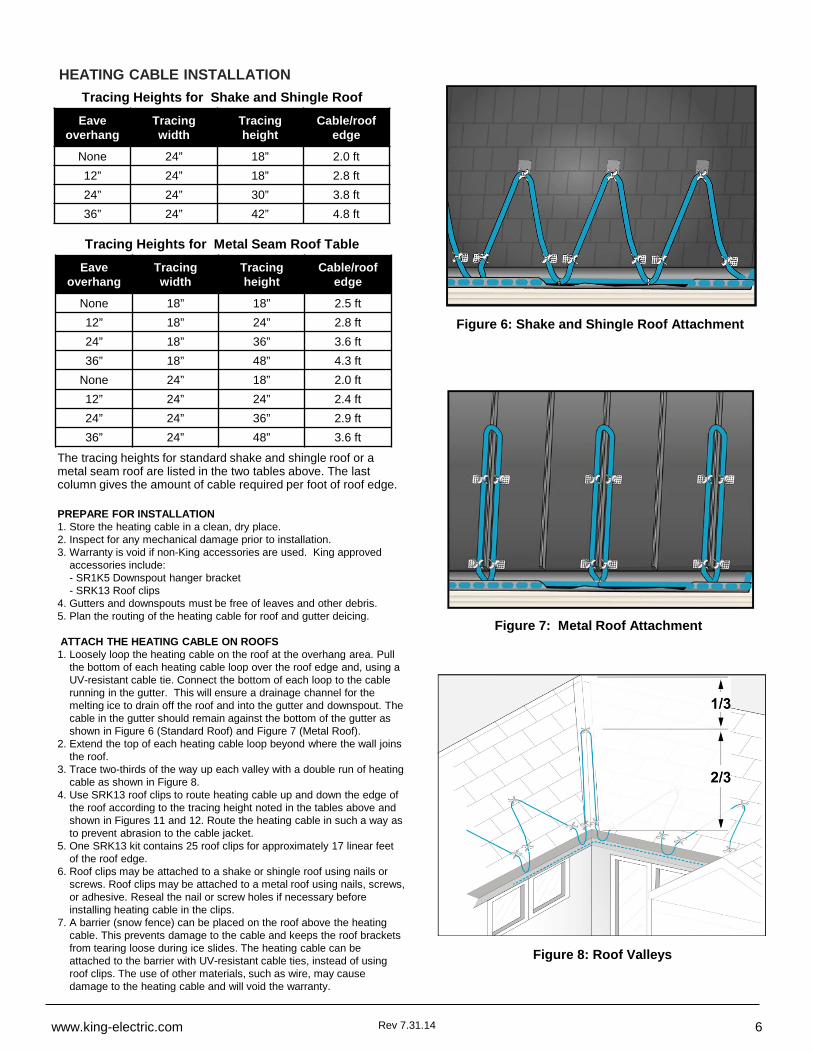
the bottom of each heating cable loop over the roof edge and, using a UV-resistant cable tie. Connect the bottom of each loop to the cable running in the gutter. This will ensure a drainage channel for the melting ice to drain off the roof and into the gutter and downspout. The cable in the gutter should remain against the bottom of the gutter as shown in Figure 6 (Standard Roof) and Figure 7 (Metal Roof).
2. Extend the top of each heating cable loop beyond where the wall joins the roof.
3. Trace two-thirds of the way up each valley with a double run of heating cable as shown in Figure 8.
4. Use SRK13 roof clips to route heating cable up and down the edge of the roof according to the tracing height noted in the tables above and shown in Figures 11 and 12. Route the heating cable in such a way as to prevent abrasion to the cable jacket.
5. One SRK13 kit contains 25 roof clips for approximately 17 linear feet of the roof edge.
6. Roof clips may be attached to a shake or shingle roof using nails or screws. Roof clips may be attached to a metal roof using nails, screws, or adhesive. Reseal the nail or screw holes if necessary before installing heating cable in the clips.
7. A barrier (snow fence) can be placed on the roof above the heating cable. This prevents damage to the cable and keeps the roof brackets from tearing loose during ice slides. The heating cable can be attached to the barrier with UV-resistant cable ties, instead of using roof clips. The use of other materials, such as wire, may cause damage to the heating cable and will void the warranty.
Figure 6: Shake and Shingle Roof Attachment
Figure 7: Metal Roof Attachment
Eaveoverhang
Tracing width
Tracingheight
Cable/roof edge
None 24” 18” 2.0 ft 12” 24” 18” 2.8 ft24” 24” 30” 3.8 ft36” 24” 42” 4.8 ft
Eaveoverhang
Tracing width
Tracingheight
Cable/roof edge
None 18” 18” 2.5 ft12” 18” 24” 2.8 ft24” 18” 36” 3.6 ft36” 18” 48” 4.3 ft
None 24” 18” 2.0 ft12” 24” 24” 2.4 ft24” 24” 36” 2.9 ft36” 24” 48” 3.6 ft
HEATING CABLE INSTALLATIONTracing Heights for Shake and Shingle Roof
Table
Tracing Heights for Metal Seam Roof Table
The tracing heights for standard shake and shingle roof or a metal seam roof are listed in the two tables above. The last column gives the amount of cable required per foot of roof edge.
Figure 8: Roof Valleys
Rev 7.31.14www.king-electric.com 6
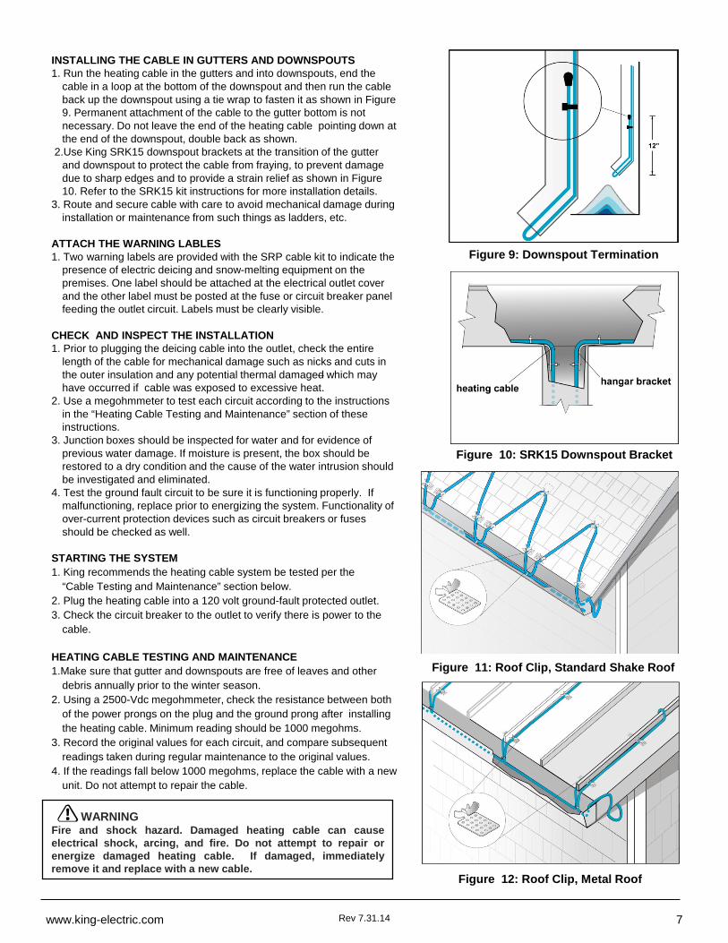
INSTALLING THE CABLE IN GUTTERS AND DOWNSPOUTS1. Run the heating cable in the gutters and into downspouts, end the
cable in a loop at the bottom of the downspout and then run the cable back up the downspout using a tie wrap to fasten it as shown in Figure 9. Permanent attachment of the cable to the gutter bottom is not necessary. Do not leave the end of the heating cable pointing down at the end of the downspout, double back as shown.
2.Use King SRK15 downspout brackets at the transition of the gutter and downspout to protect the cable from fraying, to prevent damage due to sharp edges and to provide a strain relief as shown in Figure 10. Refer to the SRK15 kit instructions for more installation details.
3. Route and secure cable with care to avoid mechanical damage during installation or maintenance from such things as ladders, etc.
ATTACH THE WARNING LABLES1. Two warning labels are provided with the SRP cable kit to indicate the
presence of electric deicing and snow-melting equipment on the premises. One label should be attached at the electrical outlet cover and the other label must be posted at the fuse or circuit breaker panel feeding the outlet circuit. Labels must be clearly visible.
CHECK AND INSPECT THE INSTALLATION1. Prior to plugging the deicing cable into the outlet, check the entire
length of the cable for mechanical damage such as nicks and cuts in the outer insulation and any potential thermal damaged which may have occurred if cable was exposed to excessive heat.
2. Use a megohmmeter to test each circuit according to the instructions in the “Heating Cable Testing and Maintenance” section of these instructions.
3. Junction boxes should be inspected for water and for evidence of previous water damage. If moisture is present, the box should be restored to a dry condition and the cause of the water intrusion should be investigated and eliminated.
4. Test the ground fault circuit to be sure it is functioning properly. If malfunctioning, replace prior to energizing the system. Functionality of over-current protection devices such as circuit breakers or fuses should be checked as well.
STARTING THE SYSTEM1. King recommends the heating cable system be tested per the
“Cable Testing and Maintenance” section below.2. Plug the heating cable into a 120 volt ground-fault protected outlet.3. Check the circuit breaker to the outlet to verify there is power to the
cable.
HEATING CABLE TESTING AND MAINTENANCE1.Make sure that gutter and downspouts are free of leaves and other
debris annually prior to the winter season.2. Using a 2500-Vdc megohmmeter, check the resistance between both
of the power prongs on the plug and the ground prong after installing the heating cable. Minimum reading should be 1000 megohms.
3. Record the original values for each circuit, and compare subsequent readings taken during regular maintenance to the original values.
4. If the readings fall below 1000 megohms, replace the cable with a new unit. Do not attempt to repair the cable.
Figure 9: Downspout Termination
Figure 10: SRK15 Downspout Bracket
WARNINGFire and shock hazard. Damaged heating cable can causeelectrical shock, arcing, and fire. Do not attempt to repair orenergize damaged heating cable. If damaged, immediatelyremove it and replace with a new cable.
Figure 11: Roof Clip, Standard Shake Roof
Figure 12: Roof Clip, Metal Roof
Rev 7.31.14www.king-electric.com 7
SRP series
9131 10th Avenue SouthSeattle, WA 98108
Tel: 800.603.5464 – Fax: 206-763-7738www.king-electric.com