prb fabry-perot
DESCRIPTION
This article describes the fabry perot resonances.TRANSCRIPT
Tuning Fabry-Perot resonances via diffraction evanescent waves
Bo Hou,1 Jun Mei,1 Manzhu Ke,2 Weijia Wen,1,* Zhengyou Liu,2 Jing Shi,2 and Ping Sheng1
1Department of Physics, Hong Kong University of Science and Technology, Clear Water Bay, Kowloon, Hong Kong, China2Department of Physics, Wuhan University, Wuhan 430072, China
�Received 22 June 2007; published 14 August 2007�
By studying acoustic and electromagnetic wave transmission through a periodic array of subwavelengthholes or slits with various channel lengths, we demonstrate both experimentally and theoretically that diffrac-tion evanescent waves can play an important role in tuning the Fabry-Perot �FP� resonances. In particular, therecan be total transmission peaks at wavelengths much below that of the Rayleigh-Wood limit, and FP reso-nances can occur for channel length �16% thinner than the half wavelength. In addition, the FP resonancecondition can be tuned via both the periodicity and area fraction of holes. As a function of the ratio between theperiodicity and plate thickness, the FP resonance is smoothly linked to the surface-wave-like mode induced bythe periodic structure factor.
DOI: 10.1103/PhysRevB.76.054303 PACS number�s�: 43.35.�d, 43.40.�s, 43.90.�v
I. INTRODUCTION
Fabry-Perot �FP� resonance is one of the most basic andcommon phenomena in both classical and quantum physics.It is a direct manifestation of the constructive or destructivewave interference over a certain path length and can lead tomultiple transmission peaks as a function of frequency forwave transmission through impedance-mismatched layers.There is a renewed interest in electromagnetic FP reso-nances, especially their relevance to the recently observedtransmission enhancement through subwavelength openingsin normally opaque objects,1–8 as well as to the ensuing de-bate on the relative contributions of surface wave versus dif-fraction in such phenomena.9–19
It has been shown that light transmission through holearrays in perfect-conductor thin films, where there can be notrue surface waves, may be attributed �via Babinet’s prin-ciple� to the reflection by the complementary structure con-sisting of planar arrays of perfect-conductor disks.17,18 Trans-mission can always reach unity at some resonantwavelengths regardless of how small the holes are, while thecomplementary system can exhibit perfect reflection for ar-bitrarily small disks. These resonances were found to be as-sociated with the divergence in structure factor, owing to thecoherent addition of the scatterings from the periodic arrayof disks or holes. As a result, a quasisurface mode with fre-quency close to the onset of the first diffraction order �wave-length � slightly larger than the lattice constant a� alwaysexists. Such modes are denoted “structure-factor-inducedsurface modes,” or SF resonances. As the structure factormechanism is valid for either the electromagnetic or theacoustic wave, it is expected that such a resonant transmis-sion mechanism also applies to �scalar� acoustic waves. Forcompleteness, we present in the Appendix the relevant argu-ments for the SF induced resonant transmission for both theelectromagnetic and acoustic waves.
In a separate development, it was found that total electro-magnetic wave transmission through subwavelength open-ings can also be associated with FP resonances. Inside thesubwavelength openings, either in slit11–14 or annulargeometry,15 standing wave patterns are formed along the lon-gitudinal direction, giving rise to FP resonances.
The purpose of this work is to show through both theoryand experiment that for thick hole arrays, the FP resonancesand the SF resonances are in fact the two limits of a singleresonance phenomenon, for both the acoustic and electro-magnetic waves. Whereas the FP resonance is characterizedby constructive interference along the channel direction, theSF-induced resonance is induced by lateral coupling. Byvarying the plate thickness or channel length, one makes thetransition from the FP resonance �thick plate limit� to the SFresonance �thin plate limit�. Between the two limits there canbe interesting deviation from FP resonance conditions, owingto the interaction of the diffraction evanescent waves. In par-ticular, it is shown that acoustic and electromagnetic FP reso-nant transmissions can occur not only at frequencies muchbelow the Rayleigh-Wood limit, but also for channel �path�lengths significantly lower than the minimum half wave-length usually required, tunable by varying either the period-icity or the area fraction of holes, or both.
II. SAMPLES AND MEASUREMENTS
We first consider ultrasound transmission through a brassplate of thickness t, immersed in water. A square lattice arrayof circular holes with radius r were drilled on the plate, withlattice constant a�2r. A schematic picture of the unit cell isshown as an inset to Fig. 1�a�. The ultrasonic transmissionmeasurements in the regime of 0.2–0.8 MHz were done in alarge water tank. Two transducers were employed as ultra-sonic generator and receiver, and the sample was placed be-tween the two transducers. The ultrasonic beam was nor-mally incident upon the sample and the transmitted signalwas collected by the receiver, collinear with the incidentwave. The transmission of ultrasonic waves through asmooth brass plate was also measured as the reference. Apartfrom measuring the far-field transmission, we have alsoimplemented near-field scanning to identify the role of sur-face waves, if any, in the transmission process. A pinducerwith a diameter of 1.5 mm was mounted on a two-dimensional translation stage and brought to a distance, z,from the rear surface of the sample to detect the surface fielddistribution. Scanning was done along the x-y plane parallel
PHYSICAL REVIEW B 76, 054303 �2007�
1098-0121/2007/76�5�/054303�6� ©2007 The American Physical Society054303-1
to the brass plate surface, with a spatial resolution of 0.1�0.1 mm2.
For the electromagnetic �EM� case, we consider micro-wave transmission through a metallic grating constructed bystacking aluminum-alloy slabs with spacers at both ends. Aschematic picture of the unit cell structure is shown as aninset to Fig. 1�b�. A microwave of 1–12 GHz emitted from ahorn antenna was normally incident with the electrical fieldperpendicular to the slits. By employing different-sized slabswe measured three cases of periodicity-to-thickness ratio=0.74, 1.48, and 2.95, with the area fraction of slits main-tained at 32%.
There is a difference between the acoustic FP resonancefrom the electromagnetic case, owing to the existence of thescalar channel that allows the propagation of an acoustic
wave through holes whose transverse dimensions aresubwavelength.20 The simplified cases of a thin screen,21,22 asingle circular channel,23,24 and one-dimensional slits25 havereceived extensive prior attention. Specifically, we considerhere the acoustic transmission in the case of very long chan-nels and found FP-like multiple transmission peaks appear-ing at wavelengths much below the diffraction limit, noted todiffer from that studied in Ref. 25.
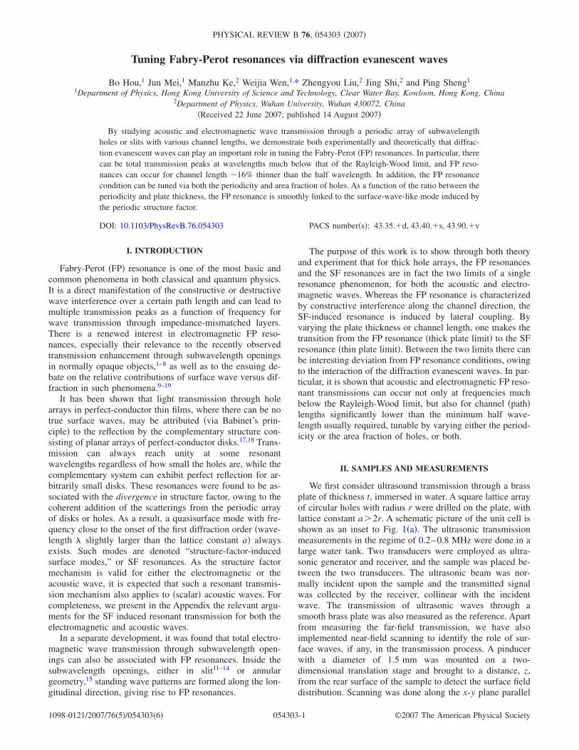
In Fig. 1�a� we show the measured acoustic wave trans-mission as a function of frequency. It is seen that there canbe multiple transmission peaks well below the Rayleigh-Wood frequency �the diffraction limit, indicated by the ar-row, corresponds to the wavelength �=a at normal inci-dence�. A smooth brass plate of thickness 2.0 mm has a verylow transmittance of �10% within the measured frequencyregime, whereas for the structured brass plate two peaks at0.310 and 0.598 MHz were observed, in good agreementwith the calculations to be described below. However, thepeak frequencies display no direct correlation with the FPresonance condition. In Fig. 1�b�, the EM transmission dataare shown. Three transmission peaks are seen. They likewisedo not correspond with the usual FP resonance condition.
III. THEORETICAL MODEL
In order to establish a useful model, we first note that therelevant ultrasonic frequencies ��2� /, where = fr
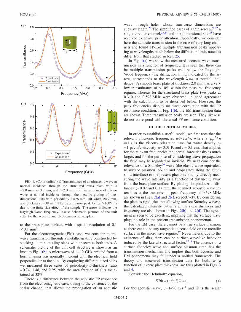
2 /��1 s is the viscous relaxation time for water density f=1 g/cm3, viscosity �=0.01 P, and r�0.1 cm. That impliesfor the relevant frequencies the inertial force density is muchlarger, and for the purpose of considering wave propagationthe fluid may be regarded as inviscid. We next consider therelevance of a Stoneley26 wave �the elastic wave equivalentto surface plasmon, bound and propagates along the fluid-solid interface� to the present phenomenon, by directly mea-suring the wave intensity as a function of distance z awayfrom the brass plate surface. By placing the pinducer at dis-tances z=0.02 and 0.17 mm, the scanned acoustic wave in-tensities at the transmission peak frequency of 0.598 MHzare shown in Figs. 2�a� and 2�c�, respectively. By consideringthe plate as rigid �thus not allowing surface Stoneley waves�,the calculated intensity patterns at the same distances andfrequency are also shown in Figs. 2�b� and 2�d�. The agree-ment is seen to be excellent, implying that the surface waveplays no role in the present transmission phenomenon.
For the EM case, there cannot be a true surface plasmon,as there cannot be any tangential electric field on the metallicsurface in the microwave regime.27 Nevertheless, due to theexistence of slits, there can be surface-wave-like behaviorinduced by the lateral structural factor.17,18 The absence of asurface Stoneley wave and surface plasmon simplifies thetransmission mechanism and implies that both acoustic andEM phenomena may fall under a unified framework. Thetheory and measured transmission data for both, as afunction of inverse plate thickness, are thus plotted in Figs. 3and 4.
Consider the Helmholtz equation,
�2� + ��2/c2�� = 0. �1�
For the acoustic wave, c=1490 m s−1 and � is the scalar
0.2 0.3 0.4 0.5 0.6 0.7 0.80.0
0.2
0.4
0.6
0.8
1.0T
rans
mitt
ance
Frequency(MHz)
ExperimentCalculation
2 4 6 8 10 120.0
0.2
0.4
0.6
0.8
1.0
ExperimentCalculation
Tra
nsm
ittan
ce
Frequency (GHz)
ta
r
d
t
a
(b)
(a)
FIG. 1. �Color online� �a� Transmittance of an ultrasonic wave atnormal incidence through the structured brass plate with a=2.0 mm, r=0.6 mm, and t=2.0 mm. �b� Transmittance of micro-wave at normal incidence through the metallic grating of one-dimensional slits with periodicity a=28 mm, slit width d=9 mm,and thickness t=38 mm. The transmission peak being �100% isdue to the finite size effect of the sample. The arrow indicates theRayleigh-Wood frequency. Insets: Schematic pictures of the unitcells for the acoustic and electromagnetic samples.
HOU et al. PHYSICAL REVIEW B 76, 054303 �2007�
054303-2
velocity potential. For the EM case, c=3.0�108 m s−1 and�=Hy �the component parallel to the slit�. From � the localdisplacement velocity is obtained as v� =�� and pressure p �� /�t. Given the magnetic field, the electric field is given
by E� = �i /���� �H� . The potential can be expanded in termsof the waveguide modes inside the hole �Eq. 2a� for theacoustic wave case� or slit �Eq. �2b� for the EM wave case�as
�1 = ��n
J0��n��An exp�− �nz� + Bn exp��nz�� , �2a�
�n
cos��n�/d��x + d/2���En exp�− i�nz� + Fn exp�i�nz�� . �2b�In Eq. �2a�, �n
2−�n2=�2 /c2,
dJ0��n�
d =r=0, where r is the radius of each hole, J0 denotes the zeroth order Bessel function, isthe transverse radial coordinate, and �n=xn /r is the radial wave vector, with xn being the nth zero of J0. In Eq. �2b� , �n
=��� /c�2− �n� /d�2, d is the width of each slit. The potentials in front of and behind the plate are expanded, respectively, as
�2 = �P exp�i�z/c� + �G�
CG� exp�iG� · ��exp�− i���/c�2 − G2z� , �3a�
P exp�i�z/c� + �m
Km exp�i2m�x/a�exp�− i���/c�2 − �2m�/a�2z� , �3b�and
�3 = ��G�
DG� exp�iG� · ��exp�i���/c�2 − G2z� , �4a�
�m
Lm exp�i2m�x/a�exp�i���/c�2 − �2m�/a�2z� , �4b� ,
where the normally incident wave amplitude is denoted by P,
G� =n12�a x+n2
2�a y with n1 and n2 being integers, and a denot-
ing the periodicity for both the hole arrays �in the sonic case�and of the metallic grating �in the microwave case�. Theoblique incidence case can be similarly treated by modifyingthe expansions for �2 and �3. By requiring continuity of vz
and p at the interfaces between �1, �2, and �3 over the holeregion, vanishing vz elsewhere on the interfaces for theacoustic wave, by requiring the continuity of Hy and Ex at thesurfaces of the grating over the slit region, and vanishing Ex
elsewhere on the interfaces, we obtain the necessary equa-tions for the solution of reflection and transmission coeffi-cients. Resonance modes are obtained by setting P=0. It canbe seen from Fig. 3 that the EM wave transmission frequen-cies for a metallic gratings with d /a=0.32 have identicalbehavior as the acoustic case for a hole array with r /a=0.30.
The predictions of the theory, as well as the experimentalresults, are shown in Figs. 1�a� and 1�b�. It is seen that withno adjustable parameters, the agreement is very good, espe-cially in the positions of the transmission peaks. For the EMcase, the solid line in this case is obtained from the finite-difference time-domain simulation.28
0
0.16
0.32(c)
Experiment
0
1.35
2.70(d)
Theory
0
1.66
3.30(b)
Theory
0
0.18
0.35(a)
Experiment
FIG. 2. �Color online� Intensity distributions of pressure field atthe rear surface of the sample for two selected distances, z=0.02and 0.17 mm, at the resonance frequency of 0.598 MHz. Thesample has the same parameter values as those in Fig. 1. �a� and �b�are the measured and calculated field pattern at z=0.02 mm, respec-tively; �c� and �d� are the same for z=0.17 mm, respectively. Theholes are delineated by dashed lines.
TUNING FABRY-PEROT RESONANCES VIA DIFFRACTION… PHYSICAL REVIEW B 76, 054303 �2007�
054303-3
IV. CHARACTERISTICS OF THE TRANSMISSIONRESONANCES
We wish to show that the observed transmission peaks arethe manifestation of a type of resonance mode that has FPand SF resonances as the two limits. The diffraction evanes-cent modes play an important role in interpolating betweenthe two limits. To make explicit the role of diffraction eva-nescent modes, we resort to analyzing the acoustic problemby retaining only one cylindrical mode �J0��1�=J0�0�=1�and five plane wave modes �G� = �0,0� and G� = �±1, ±1� 2�
a �,both in �2 and �3. In principle, by keeping more cylindricalmodes and more plane wave modes, the results obtainedshould be more accurate, but they do not add to the physicalunderstating. With the minimal number of modes, the result-ing resonant mode equation for the acoustic case can be ex-pressed as
tan�2t�/c� =− a3k0k1
2
��1 − f2�16J1
2�2�r/a�a3k1
3 + �22a
t
, �5�
in which k0=� /c, k1=��2� /a�2− �� /c�2 is the diffractionevanescent wave vector, f denotes the area fraction of holes,and J1 is the first order Bessel function. Equation �5� is in-structive, since a vanishing right-hand side would directlyyield the FP resonance condition, t=n� /2, � being the wave-length. A combination of hole and periodic diffraction eva-
nescent wave effects constitute the correction to the usual FPcondition in the form of a nonzero right-hand side, implyingthat the FP resonance can be tuned by varying the periodicityand area fraction of holes. We denote such resonances theFPEV resonances �EV means evanescent wave�.
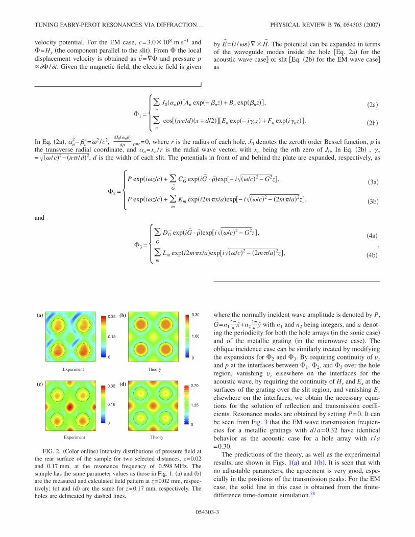
In Fig. 3 we show the FPEV resonance frequencies plot-ted as a function of inverse plate thickness. The FP conditionis indicated by the black dashed straight lines, for n=1–4,with slopes of 0.5, 1, 1.5, and 2, respectively. The FPEVfrequencies are shown as solid black �normal incidence� andred and green �30° oblique incidence� lines. Compared withthe FP resonances, it is seen that the FPEV resonances al-ways occur at lower frequencies, as though the effectiveplate thickness is greater than t. The prediction of Eq. �5�, forthe n=1 FPEV resonance, is shown as the blue line. Exceptin the region of very small a / t values, the blue line has aslope of 0.42. Thus the effect of the diffraction evanescentwaves is to shift the resonance condition by �16%, in thedirection of smaller channel length. The difference betweenthe prediction of Eq. �5� and the red and green lines appearsat the small t limit, where the transmission peak frequencyshows a clear dependence on the incidence angle. This ischaracteristic of the surface-wave-like mode induced by theSF resonance.17,18 In fact, these transmission peak frequen-cies all occur at close to the Rayleigh-Wood limit, as re-quired by the SF resonance condition. Thus the lowest fre-quency FPEV resonance, which shows little or nodependence on the incidence angle, is smoothly converted tothe structure-factor-induced surface mode in the thin-platelimit. The diffraction evanescent wave contributions aredominant at the intermediate values of a / t. To a lesser de-gree, similar behavior can be observed for the higher orderFPEVs.
In the same figure we also show �the magenta line� theprediction of the EM wave case for a metallic grating. Thefact that the acoustic and EM curves are almost identicalimplies a unified framework for the underlying mechanism,as expected.
It is seen that as the ratio a / t increases, the lowest orderevanescent waves �Eq. �5�� can no longer account for theresonant frequency trajectory. Also, in the large a / t limit thecurves also display pronounced incident angle dependence,in contrast to FP resonances, which are nearly independent ofthe incidence angle. These are the signals for �1� the lateralscattering interaction is contributing much more to the reso-nant modes, hence the lowest order evanescent modes are nolonger sufficient to account for such strong lateral interac-tions, and �2� with the increased lateral interaction, the SFeffect becomes more pronounced, implying incidence angledependence as shown in the Appendix.
The inset to Fig. 3 shows the FPEV’s frequency depen-dence �lowest frequency mode� on r /a for the acoustic case.There is a clear minimum, indicating a competition betweenthe single-hole evanescent wave diffraction effect and theinfluence of periodic array on a single hole. Only when thetwo effects are constructively combined, the biggest devia-tion from the usual FP resonant condition is achieved, asshown in the inset.
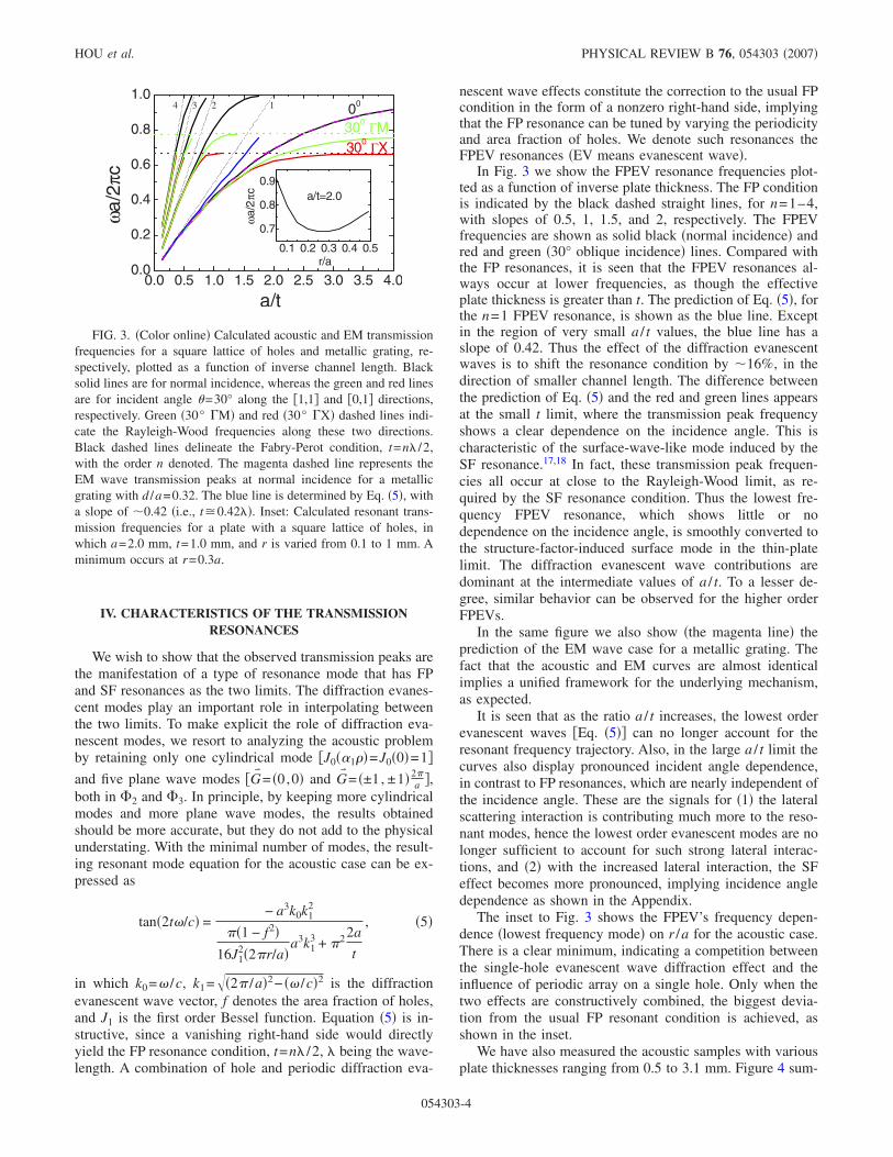
We have also measured the acoustic samples with variousplate thicknesses ranging from 0.5 to 3.1 mm. Figure 4 sum-
0.0 0.5 1.0 1.5 2.0 2.5 3.0 3.5 4.00.0
0.2
0.4
0.6
0.8
1.0
0.1 0.2 0.3 0.4 0.5
0.7
0.8
0.9
ωa/
2πc
r/a
a/t=2.0
00
300 ΓX300 ΓM
ωa/2
πc
a/t
1234
FIG. 3. �Color online� Calculated acoustic and EM transmissionfrequencies for a square lattice of holes and metallic grating, re-spectively, plotted as a function of inverse channel length. Blacksolid lines are for normal incidence, whereas the green and red linesare for incident angle �=30° along the �1,1� and �0,1� directions,respectively. Green �30° �M� and red �30° �X� dashed lines indi-cate the Rayleigh-Wood frequencies along these two directions.Black dashed lines delineate the Fabry-Perot condition, t=n� /2,with the order n denoted. The magenta dashed line represents theEM wave transmission peaks at normal incidence for a metallicgrating with d /a=0.32. The blue line is determined by Eq. �5�, witha slope of �0.42 �i.e., t�0.42��. Inset: Calculated resonant trans-mission frequencies for a plate with a square lattice of holes, inwhich a=2.0 mm, t=1.0 mm, and r is varied from 0.1 to 1 mm. Aminimum occurs at r=0.3a.
HOU et al. PHYSICAL REVIEW B 76, 054303 �2007�
054303-4
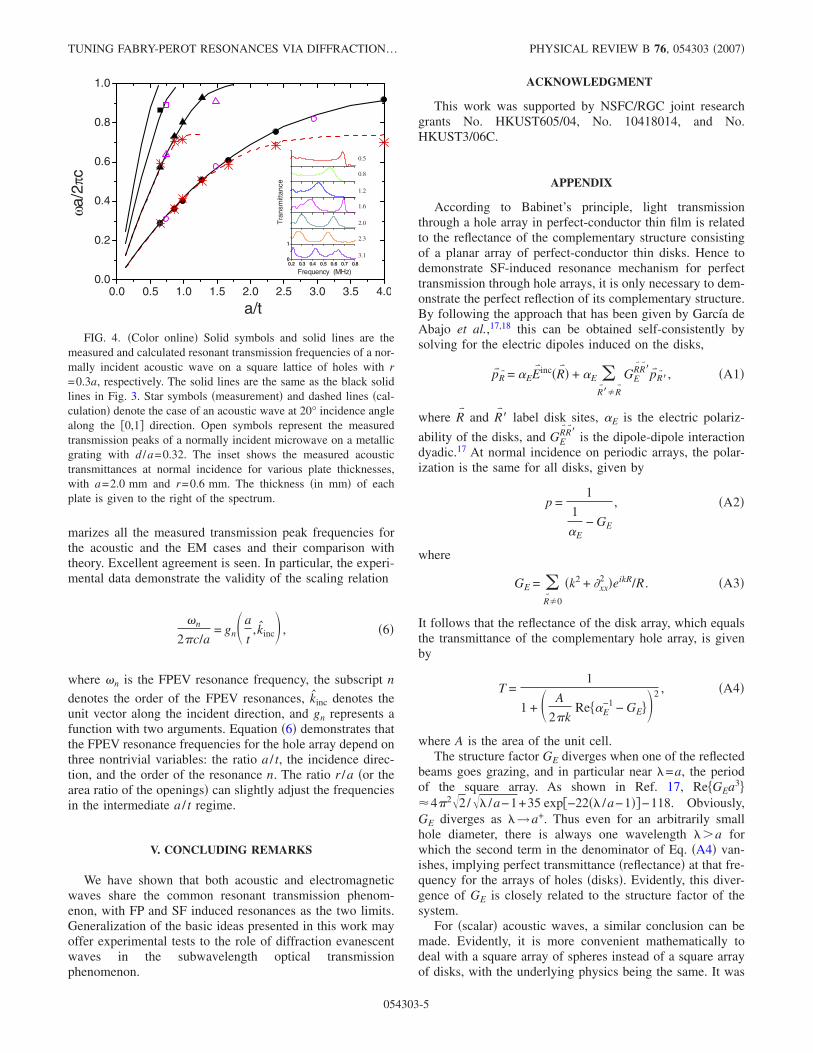
marizes all the measured transmission peak frequencies forthe acoustic and the EM cases and their comparison withtheory. Excellent agreement is seen. In particular, the experi-mental data demonstrate the validity of the scaling relation
�n
2�c/a= gn�a
t, kinc , �6�
where �n is the FPEV resonance frequency, the subscript n
denotes the order of the FPEV resonances, kinc denotes theunit vector along the incident direction, and gn represents afunction with two arguments. Equation �6� demonstrates thatthe FPEV resonance frequencies for the hole array depend onthree nontrivial variables: the ratio a / t, the incidence direc-tion, and the order of the resonance n. The ratio r /a �or thearea ratio of the openings� can slightly adjust the frequenciesin the intermediate a / t regime.
V. CONCLUDING REMARKS
We have shown that both acoustic and electromagneticwaves share the common resonant transmission phenom-enon, with FP and SF induced resonances as the two limits.Generalization of the basic ideas presented in this work mayoffer experimental tests to the role of diffraction evanescentwaves in the subwavelength optical transmissionphenomenon.
ACKNOWLEDGMENT
This work was supported by NSFC/RGC joint researchgrants No. HKUST605/04, No. 10418014, and No.HKUST3/06C.
APPENDIX
According to Babinet’s principle, light transmissionthrough a hole array in perfect-conductor thin film is relatedto the reflectance of the complementary structure consistingof a planar array of perfect-conductor thin disks. Hence todemonstrate SF-induced resonance mechanism for perfecttransmission through hole arrays, it is only necessary to dem-onstrate the perfect reflection of its complementary structure.By following the approach that has been given by García deAbajo et al.,17,18 this can be obtained self-consistently bysolving for the electric dipoles induced on the disks,
p�R� = �EE� inc�R� � + �E �R���R�
GER� R��p�R��, �A1�
where R� and R� � label disk sites, �E is the electric polariz-
ability of the disks, and GER� R�� is the dipole-dipole interaction
dyadic.17 At normal incidence on periodic arrays, the polar-ization is the same for all disks, given by
p =1
1
�E− GE
, �A2�
where
GE = �R��0
�k2 + �xx2 �eikR/R . �A3�
It follows that the reflectance of the disk array, which equalsthe transmittance of the complementary hole array, is givenby
T =1
1 + � A
2�kRe��E
−1 − GE� 2 , �A4�
where A is the area of the unit cell.The structure factor GE diverges when one of the reflected
beams goes grazing, and in particular near �=a, the periodof the square array. As shown in Ref. 17, Re�GEa3��4�2�2/�� /a−1+35 exp�−22�� /a−1��−118. Obviously,GE diverges as �→a+. Thus even for an arbitrarily smallhole diameter, there is always one wavelength ��a forwhich the second term in the denominator of Eq. �A4� van-ishes, implying perfect transmittance �reflectance� at that fre-quency for the arrays of holes �disks�. Evidently, this diver-gence of GE is closely related to the structure factor of thesystem.
For �scalar� acoustic waves, a similar conclusion can bemade. Evidently, it is more convenient mathematically todeal with a square array of spheres instead of a square arrayof disks, with the underlying physics being the same. It was
0.0 0.5 1.0 1.5 2.0 2.5 3.0 3.5 4.00.0
0.2
0.4
0.6
0.8
1.0ωa
/2πc
a/t
0.2 0.3 0.4 0.5 0.6 0.7 0.80
1
Tra
nsm
ittan
ceFrequency (MHz)
0.5
0.8
1.2
1.6
2.0
2.3
3.1
FIG. 4. �Color online� Solid symbols and solid lines are themeasured and calculated resonant transmission frequencies of a nor-mally incident acoustic wave on a square lattice of holes with r=0.3a, respectively. The solid lines are the same as the black solidlines in Fig. 3. Star symbols �measurement� and dashed lines �cal-culation� denote the case of an acoustic wave at 20° incidence anglealong the �0,1� direction. Open symbols represent the measuredtransmission peaks of a normally incident microwave on a metallicgrating with d /a=0.32. The inset shows the measured acoustictransmittances at normal incidence for various plate thicknesses,with a=2.0 mm and r=0.6 mm. The thickness �in mm� of eachplate is given to the right of the spectrum.
TUNING FABRY-PEROT RESONANCES VIA DIFFRACTION… PHYSICAL REVIEW B 76, 054303 �2007�
054303-5
shown29 that the far-field scattering amplitude of a sound-soft sphere �with radius a� induced by a plane incident wavecan be written as −a eikr
r in the small sphere limit of ka�1.Thus an “acoustic polarizability” �=−a can be similarly de-fined by self-consistently writing down the following equa-tion:
pR� = �I�R� � + � �R���R�
GR� R��pR��, �A5�
where R� and R� � label the sphere sites, pR� is the secondary
source strength at position R⇀, I�R� denotes the incident
acoustic field, and GR� R�� is the acoustic field at R� induced by
the scattered field of the sphere at R� �. At normal incidence onperiodic arrays, the “acoustic polarization” is the same for allspheres, given by
p =1
1
�− G
I , �A6�
where
G = �R��0
eikR/R . �A7�
Just like the EM wave case, G diverges as �→a+. Thus,given an arbitrarily small sphere radius a, there is always onewavelength ��a for which the denominator of Eq. �A6�vanishes, implying the coherent interaction of all the spheres,leading to the divergence of the acoustic impedance of thesquare array of the spheres. At this resonant frequency, thereflection from the sphere or disk array would be 100% dueto the divergence of its impedance. From Babinet’s principle,acoustic transmission through the hole arrays in a thin rigidslab can reach 100% due to the SF mechanism.
It should be noted that for the SF induced mechanism, theresonance frequency can vary with the incidence angle.When the light �or sound� wave is obliquely incident with anincident angle �i, the divergence frequency �d of the struc-ture factor G should be determined by the condition that thefirst-order diffraction beam becomes tangent to the plane ofgrating, i.e., �d=2�c / �a�1+sin �i��. It follows that the reso-nant transmission frequency is also dependent on the inci-dent angle since the resonant frequency is slightly smallerthan the divergence frequency �d.
*Corresponding author. [email protected] T. W. Ebbesen, H. J. Lezec, H. F. Ghaemi, T. Thio, and P. A.
Wolff, Nature �London� 391, 667 �1998�.2 H. F. Ghaemi, T. Thio, D. E. Grupp, T. W. Ebbesen, and H. J.
Lezec, Phys. Rev. B 58, 6779 �1998�.3 D. E. Grupp, H. J. Lezec, T. W. Ebbesen, K. M. Pellerin, and T.
Thio, Appl. Phys. Lett. 77, 1569 �2000�.4 A. Krishnan, T. Thio, T. J. Kim, H. J. Lezec, T. W. Ebbesen, P. A.
Wolff, J. Pendry, L. Martin-Moreno, and F. J. Garcia-Vidal, Opt.Commun. 200, 1 �2001�.
5 L. Martín-Moreno, F. J. García-Vidal, H. J. Lezec, K. M. Pellerin,T. Thio, J. B. Pendry, and T. W. Ebbesen, Phys. Rev. Lett. 86,1114 �2001�.
6 W. L. Barnes, W. A. Murray, J. Dintinger, E. Devaux, and T. W.Ebbesen, Phys. Rev. Lett. 92, 107401 �2004�.
7 L. Martín-Moreno and F. J. García-Vidal, Opt. Express 12, 3619�2004�.
8 W. L. Barnes, A. Dereux, and T. W. Ebbesen, Nature �London�424, 824 �2003�.
9 M. M. J. Treacy, Phys. Rev. B 66, 195105 �2002�.10 H. J. Lezec and T. Thio, Opt. Express 12, 3629 �2004�.11 J. A. Porto, F. J. García-Vidal, and J. B. Pendry, Phys. Rev. Lett.
83, 2845 �1999�.12 H. E. Went, A. P. Hibbins, J. R. Sambles, C. R. Lawrence, and A.
P. Crick, Appl. Phys. Lett. 77, 2789 �2000�.13 Y. Takakura, Phys. Rev. Lett. 86, 5601 �2001�.14 F. Yang and J. R. Sambles, Phys. Rev. Lett. 89, 063901 �2002�.15 F. I. Baida, D. V. Labeke, G. Granet, A. Moreau, and A. Belkhir,
Appl. Phys. B: Lasers Opt. 79, 1 �2004�.16 D. C. Skigin and R. A. Depine, Phys. Rev. Lett. 95, 217402
�2005�.17 F. J. García de Abajo, R. Gómez-Medina, and J. J. Sáenz, Phys.
Rev. E 72, 016608 �2005�.18 F. J. García de Abajo and J. J. Sáenz, Phys. Rev. Lett. 95, 233901
�2005�.19 S. Selcuk, K. Woo, D. B. Tanner, A. F. Hebard, A. G. Borisov,
and S. V. Shabanov, Phys. Rev. Lett. 97, 067403 �2006�.20 The condition of normal velocity must be zero at the channel wall
implies that it is the derivative of J0�=−J1� which must be zeroat the solid boundary. However, J1�0�=0, implying no cutoff forthe acoustic wave propagation in subwavelength holes. See, L.D. Landau and E. M. Lifshitz, Fluid Mechanics, 2nd ed. �Per-gamon Press, New York, 1987�.
21 H. Lamb, Hydrodynamics, 6th ed. �Dover, New York, 1991�.22 J. Miles, Wave Motion 35, 311 �2002�.23 G. P. Wilson and W. W. Soroka, J. Acoust. Soc. Am. 37, 286
�1965�.24 K. H. Jun and H. J. Eom, J. Acoust. Soc. Am. 98, 2324 �1995�.25 X. Zhang, Phys. Rev. B 71, 241102�R� �2005�.26 R. Stoneley, Proc. R. Soc. London, Ser. A 106, 416 �1924�.27 B. Hou, Z. H. Hang, W. Wen, C. T. Chan, and P. Sheng, Appl.
Phys. Lett. 89, 131917 �2006�.28 Simulations were implemented by using commercial software
CONCERTO 3.5 �Vector Fields Limited, England, 2003�. In thesimulation, a periodical boundary condition was imposed to theunit cell shown as the inset of Fig. 1�b�, and a perfect conductorapproximation was adopted.
29 Paul Martin, Multiple Scattering �Cambridge University Press,Cambridge, England, 2006�.
HOU et al. PHYSICAL REVIEW B 76, 054303 �2007�
054303-6