pradeep kshetrapal current electricity genius...
TRANSCRIPT

genius PHYSICS Pradeep Kshetrapal
Current Electricity 1
genius PHYSICS
Notes by Pradeep Kshetrapal
R
R
R
R R
R R R R
R
R R
O
Determination of resistance
V
E
+ –
vd
Electric current and Resistance
Heating effect of current
Not for circulation. Only for the students of genius PHYSICS at Rao classes,Jamanipali, genius Physics Ghantaghar Korba, and Gupta classes Kusmunda
A –
+
+ –
+ –
Cell, Kirchoff's law and Measuring instruments

genius PHYSICS Pradeep Kshetrapal
2 Current Electricity

genius PHYSICS Pradeep Kshetrapal
Current Electricity 3
Formulas in current electricity (Direct Current) 1
Electric Current i=q/t
"q" is charge passing in normal direction through a cross section of conductor in time "t"
2 Drift velocity Vd with Electric field
Vd = e is charge and m is mass on electron, E is electric field, τ is relaxation time.
3 Current I with Drift velocity Vd I = n e A Vd n is number density with of free electrons, A is area of cross section.
4 Mobility of charge “µ” µ = Vd / E =
5 Mobility and drift velocity Vd = µeE
6 Current and Mobility I= Ane x µeE
7 Resistance, P.D., and Current R = V / I
V Potential Difference, I Current .
8 Resistance R with specific Res. R =
l is length of conductor and A is area of cross section
9 Specific Resistance, ρ ρ = R
10 Resistivity with electrons ρ =
11 Current density J = I / I is current, J current density, A is area of cross section
12 Current density magnitude J A cosθ = I θ is angle between and
13 Conductance G G = 1/R
14 Conductivity
is specific resistance
15 Microscopic form of Ohms Law
J = E E is electric field
16 Temperature coefficient of Resistance
α = Ro is resistance at 0o C. Rt is resistance at to and “t” is temperature difference.
17 Resistances in series R = R1+R2+R3
Same current through all resistances (circuit Current
Resistances in parallel 1/Re = 1/R1 +1/R2 +1/R3
Same P.D. across each resistance (V of cell)
18 In a cell, emf and internal resistance
I = I is current, E is emf, R is external resistance, r is internal resistance.
19 In a circuit with a cell V = E - Ir
V is terminal potential difference
20 n Cells of emf E in series Emf = nE
21 Resistance of n cells in series nr + R
r is internal resistance of one cell, R external Resistance
22 Current in circuit with n cells in series
I = r is internal resistance of one cell, R external Resistance
23 n cells in parallel, then emf emf = E
24 n cells in parallel, resistance R + r/n
R external resistance, r internal resistance
25 Cells in mixed group, condition for maximum current
R = n is number of cells in one row, m is number of rows. r is internal resistance, R external resis.
26 Internal resistance of a cell r = ( E is emf, V is terminal Potential difference, R is external resistance.
27 Power of a circuit P = I.V = I2R = V2/R
28 Energy consumed E = I.V.∆T ∆T is time duration
29 Kirchoff Law (junction rule) Sum of currents at junction is zero.
30 Kirchoff Law (Loop rule) In a loop sum of all p.d.s is Zero

genius PHYSICS Pradeep Kshetrapal
4 Current Electricity

genius PHYSICS Pradeep Kshetrapal
Current Electricity 5
V
A
Electric Current.
(1) Definition : The time rate of flow of charge through any cross-section is called current. So if
through a cross-section, ∆Q charge passes in time ∆t then t
Qiav
∆
∆= and instantaneous current
dt
dQ
t
QLimi
t==
→ ∆
∆
0∆
. If flow is uniform then t
Qi = . Current is a scalar quantity. It's S.I. unit is ampere (A) and
C.G.S. unit is emu and is called biot (Bi), or ab ampere. 1A = (1/10) Bi (ab amp.)
(2) The direction of current : The conventional direction of current is taken to be the direction of
flow of positive charge, i.e. field and is opposite to the direction of flow of negative charge as shown below.
Though conventionally a direction is associated with current (Opposite to the motion of electron), it is not a vector. It is because the current can be added algebraically. Only scalar quantities can be added algebraically not the vector quantities.
(3) Charge on a current carrying conductor : In conductor the current is caused by electron (free electron). The no. of electron (negative charge) and proton (positive charge) in a conductor is same. Hence the net charge in a current carrying conductor is zero.
(4) Current through a conductor of non-uniform cross-section : For a given conductor current does not change with change in cross-sectional area. In the following figure i1 = i2 = i3
(5) Types of current : Electric current is of two type :
Alternating current (ac) Direct current (dc)
(i)
Magnitude and direction both
varies with time
ac → Rectifier → dc
(ii) Shows heating effect only
(i) (Pulsating dc) (Constant dc)
dc → Inverter → ac
(ii) Shows heating effect, chemical effect and magnetic effect of current
(iii) It’s symbol is (iii) It’s symbol is
Note : In our houses ac is supplied at 220V, 50Hz.
(6) Current in difference situation :
(i) Due to translatory motion of charge
In n particle each having a charge q, pass through a given area in time t then t
nqi =
If n particles each having a charge q pass per second per unit area, the current associated with cross-
sectional area A is nqAi =
If there are n particle per unit volume each having a charge q and moving with velocity v, the current
thorough, cross section A is nqvAi = , for electrons i= neavd
+
+
+
+
+
+
i
Er
i
Er
+
–
i
t
i
t
i
t
+ – ~
i2 i1 i3
genius PHYSICS Pradeep Kshetrapal
6 Current Electricity
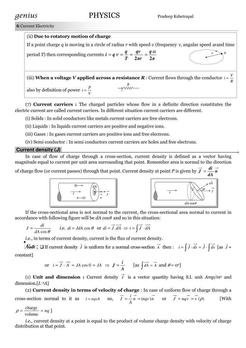
(ii) Due to rotatory motion of charge
If a point charge q is moving in a circle of radius r with speed v (frequency ν, angular speed ω and time
period T) then corresponding currents π
q
πr
qv
T
qqi
22
ων ====
(iii) When a voltage V applied across a resistance R : Current flows through the conductor R
Vi =
also by definition of power V
Pi =
(7) Current carriers : The charged particles whose flow in a definite direction constitutes the
electric current are called current carriers. In different situation current carriers are different.
(i) Solids : In solid conductors like metals current carriers are free electrons.
(ii) Liquids : In liquids current carriers are positive and negative ions.
(iii) Gases : In gases current carriers are positive ions and free electrons.
(iv) Semi conductor : In semi conductors current carriers are holes and free electrons.
Current density (J).
In case of flow of charge through a cross-section, current density is defined as a vector having
magnitude equal to current per unit area surrounding that point. Remember area is normal to the direction
of charge flow (or current passes) through that point. Current density at point P is given by ndA
diJ =
If the cross-sectional area is not normal to the current, the cross-sectional area normal to current in
accordance with following figure will be dA cosθ and so in this situation:
θcosdA
diJ = i.e. θcosJdAdi = or dAJdi .= ⇒ ∫ ⋅= dAJi
i.e., in terms of current density, current is the flux of current density.
Note : If current density Jr is uniform for a normal cross-section A then : ∫∫ ⋅=⋅= dsJdsJi
rr [as J
r=
constant]
or JAJAAJi ==⋅= 0cos ⇒ A
iJ = [as AdA =∫ and θ = 0o]
(1) Unit and dimension : Current density J is a vector quantity having S.I. unit Amp/m2 and
dimension.[L–2A]
(2) Current density in terms of velocity of charge : In case of uniform flow of charge through a
cross-section normal to it as nqvAi = so, nnqvnA
iJ )(== or )(ρvvnqJ == [With
nq==volume
chargeρ ]
i.e., current density at a point is equal to the product of volume charge density with velocity of charge distribution at that point.
q r
R
i
i
dA
nJP i J θ
Ad ˆ
θ
dA cosθ

genius PHYSICS Pradeep Kshetrapal
Current Electricity 7
(3) Current density in terms of electric field : Current density relates with electric field as
ρσ
EEJ == ; where σ = conductivity and ρ = resistivity or specific resistance of substance.
(i) Direction of current density J is same as that of electric field E .
(ii) If electric field is uniform (i.e. constant=E ) current density will be constant [as σ = constant]
(iii) If electric field is zero (as in electrostatics inside a conductor), current density and hence current will be zero.
Conduction of Current in Metals.
According to modern views, a metal consists of a ‘lattice’ of fixed positively charged ions in which
billions and billions of free electrons are moving randomly at speed which at room temperature (i.e. 300 K)
in accordance with kinetic theory of gases is given by smm
kTv rms /10–~
101.9
300)1038.1(33 5
31
23
−
−
×
×××==
The randomly moving free electrons inside the metal collide with the lattice and follow a zig-zag path as
shown in figure (A).
However, in absence of any electric field due to this random motion, the number of electrons crossing
from left to right is equal to the number of electrons crossing from right to left (otherwise metal will not
remain equipotential) so the net current through a cross-section is zero.
A motion of charge is possible by motion of electron or a current carrier.
Velocities of charged particle (electron) in a conductor
thermal velocity : All electrons in the atom are not capable of motion. Only a few which have little higher level of
energy leave their orbit and are capable of moving around. These electrons are called “free electrons”. These free
electrons are in very large quantity 1029 m-3 in free metals. Due to temperature and thermal energy They have a
thermal velocity 105 ms-1 . This velocity is in all directions and of magnitudes varying from zero to maximum. Due to
large number of electrons we can assume that vector sum of thermal velocities at any instant is zero.
i.e. + + +.. . . . . +un = 0
Mean Free path : The fast moving electrons keep striking other atoms/ions in the conductor. They are reflected and
move in other direction. They keep moving till they strike another ion/atom.
The path between two consecutive collisions is called free path. The average length of these free paths is called “Mean
Free Path”.
Relaxation Time :The time to travel mean free path is called Relaxation Period or Relaxation Time, denoted by Greek
letter Tau “τ”. If t1, t2, …tn are the time periods for n collisions then Relaxation Time τ = (t1+t2+ . . .tn)
Drift Velocity :When Electric Field is applied across a conductor, the free electrons experience a force in the
direction opposite to field. Dur to this force they start drifting in the direction of force. The Velocity of this drift is
called drift velocity “Vd”. During the drift they maintain their thermal velocity.
The drift velocity can be calculated as averaged velocity of all the electrons drifting.
Relation between drift-velocity (Vd) and electric field applied.
When electric field is applied across a conductor each electron experience a Force = q in the direction of . It
acquires an acceleration α = where e is charge on electron and m is its mass.
(A)
– +
(B)

genius PHYSICS Pradeep Kshetrapal
8 Current Electricity
If n electrons are having initial speeds u1, u2,…un and their time to travel free path is t1, t2, …tn then final velocities are
v1 =u1+ αt1,
V2 = u2+ αt2 ,
Vn = un+ αtn and so on.
Drift velocity is average of these velocities of charged particles. Therefore
Vd = (v1+ V2+…….. Vn)
= (u1+ αt1+ u2+ αt2+ . . . . . . un+ αtn )
= (u1+ u2+. . . un + αt1+αt2+ . . . αtn )
= (u1+ u2+. . . un ) + (αt1+αt2+ . . . αtn )
= 0 + α (t1+t2+ . . .tn)
= α τ
or Vd = (α = )
-------------------------------------------------------------------
Relation of Current and Drift velocity : When an electric field is applied, inside the conductor
due to electric force the path of electron in general becomes curved (parabolic) instead of straight lines and
electrons drift opposite to the field figure (B). Due to this drift the random motion of electrons get modified
and there is a net transfer of electrons across a cross-section resulting in current.
Drift velocity is the average uniform velocity acquired by free electrons inside a metal by the
application of an electric field which is responsible for current through it. Drift velocity is very small it is of
the order of 10–4 m/s as compared to thermal speed )/10–~( 5sm of electrons at room temperature.
If suppose for a conductor
n = Number of electron per unit volume of the conductor
A = Area of cross-section
V = potential difference across the conductor
E = electric field inside the conductor
i = current, J = current density, ρ = specific resistance, σ = conductivity
=
ρσ
1 then current relates
with drift velocity as dneAvi = we can also write enl
V
ne
E
ne
E
ne
J
neA
iv d
ρρ
σ===== .
Note : The direction of drift velocity for electron in a metal is opposite to that of applied electric field
(i.e. current density Jr).
Evd ∝ i.e., greater the electric field, larger will be the drift velocity.
When a steady current flows through a conductor of non-uniform cross-section drift
velocity varies inversely with area of cross-section
∝
Avd
1
If diameter of a conductor is doubled, then drift velocity of electrons inside it will not change.
l
V
E
+ –
vd
A
Vd =
i
Er
i
Er

genius PHYSICS Pradeep Kshetrapal
Current Electricity 9
(2) Relaxation time (ττττ) : The time interval between two successive collisions of electrons with the
positive ions in the metallic lattice is defined as relaxation time rmsv
λτ ==
electronsof velocityr.m.s.
pathfree mean with
rise in temperature vrms increases consequently τ decreases.
(3) Mobility : Drift velocity per unit electric field is called mobility of electron i.e. E
vd=µ . It’s unit is
sec
2
−volt
m.
Concepts
Human body, though has a large resistance of the order of kΩ (say 10 kΩ), is very sensitive to minute currents even as low as
a few mA. Electrocution, excites and disorders the nervous system of the body and hence one fails to control the activity of the
body.
1 ampere of current means the flow of 6.25 × 10¹⁸ electrons per second through any cross-section of the conductors.
dc flows uniformly throughout the cross-section of conductor while ac mainly flows through the outer surface area of the
conductor. This is known as skin effect.
It is worth noting that electric field inside a charged conductor is zero, but it is non zero inside a current carrying
conductor and is given by l
VE = where V = potential difference across the conductor and l = length of the conductor.
Electric field out side the current carrying is zero.
For a given conductor JA = i = constant so that A
J1
∝ i.e., J1 A1 = J2 A2 ; this is called equation of continuity
If cross-section is constant, I ∝ J i.e. for a given cross-sectional area, greater the current density, larger will be current.
The drift velocity of electrons is small because of the frequent collisions suffered by electrons.
The small value of drift velocity produces a large amount of electric current, due to the presence of extremely large
number of free electrons in a conductor. The propagation of current is almost at the speed of light and involves
electromagnetic process. It is due to this reason that the electric bulb glows immediately when switch is on.
In the absence of electric field, the paths of electrons between successive collisions are straight line while in presence of
electric field the paths are generally curved.
Free electron density in a metal is given by A
dxNn A= where NA = Avogrado number, x = number of free electrons per
atom, d = density of metal and A = Atomic weight of metal.
Example: 1 The potential difference applied to an X-ray tube is 5 KV and the current through it is 3.2 mA. Then
the number of electrons striking the target per second is
(a) 2 × 10¹⁶ (b) 5 × 10⁶ (c) 1 × 10¹⁷ (d) 4 × 10¹⁵
Solution : (a) t
ne
t
qi == ⇒ 16
19
3
102106.1
1102.3×=
×
××==
−
−
e
itn
Ein = 0
+ + + + + +
+ + + + + +
Ein = V/l
l
+ –
i
A2 A1
J2 J1 i
Examples

genius PHYSICS Pradeep Kshetrapal
10 Current Electricity
Example: 2 A beam of electrons moving at a speed of 106 m/s along a line produces a current of 1.6 × 10⁻⁶ A. The
number of electrons in the 1 metre of the beam is [CPMT 2000]
(a) 106 (b) 107 (c) 1013 (d) 1019
Solution : (b) x
nev
x
qv
vx
q
t
qi ====
)/( ⇒ 7
619
6
1010106.1
1106.1=
××
××==
−
−
ev
ixn
Example: 3 In the Bohr’s model of hydrogen atom, the electrons moves around the nucleus in a circular orbit of
a radius 5 × 10–11 metre. It’s time period is 1.5 × 10⁻¹⁶ sec. The current associated is
(a) Zero (b) 1.6 × 10⁻¹⁹ A (c) 0.17 A (d) 1.07 × 10⁻³ A
Solution : (d) AT
qi 3
16
19
1007.1105.1
106.1 −
−
−
×=×
×==
Example: 4 An electron is moving in a circular path of radius 5.1 × 10⁻¹¹ m at a frequency of 6.8 × 10¹⁵
revolution/sec. The equivalent current is approximately
(a) 5.1 × 10⁻³ A (b) 6.8 × 10⁻³ A (c) 1.1 × 10⁻³ A (d) 2.2 × 10⁻³ A
Solution : (c) 15108.6 ×=ν ⇒ sec108.6
115×
=T ⇒ 1519108.6106.1 ×××== −
T
Qi = 1.1 × 10⁻³ A
Example: 5 A copper wire of length 1m and radius 1mm is joined in series with an iron wire of length 2m and
radius 3mm and a current is passed through the wire. The ratio of current densities in the copper and
iron wire is
[MP PMT 1994]
(a) 18 : 1 (b) 9 : 1 (c) 6 : 1 (d) 2 : 3
Solution : (b) We know A
iJ = when i = constant
AJ
1∝ ⇒⇒⇒⇒
1
9
1
322
=
=
==
c
i
c
i
i
c
r
r
A
A
J
J
Example: 6 A conducting wire of cross-sectional area 1 cm2 has 3 × 10²³ m–3 charge carriers. If wire carries a
current of 24 mA, the drift speed of the carrier is [UPSEAT 2001]
(a) 5 × 10⁻⁶ m/s (b) 5 × 10⁻³ m/s (c) 0.5 m/s (d) 5 × 10⁻² m/s
Solution : (b) smneA
iv d /105
10106.1103
1024 3
41923
3−
−−
−
×=××××
×==
Example: 7 A wire has a non-uniform cross-sectional area as shown in figure. A steady current i flows through it.
Which one of the following statement is correct
(a) The drift speed of electron is constant (b) The drift speed increases on moving from
A to B
(c) The drift speed decreases on moving from A to B (d) The drift speed varies randomly
Solution : (c) For a conductor of non-uniform cross-section section-crossof Area
1∝dv
Example: 8 In a wire of circular cross-section with radius r, free electrons travel with a drift velocity v, when a
current i flows through the wire. What is the current in another wire of half the radius and of the some
material when the drift velocity is 2v
(a) 2i (b) i (c) i/2 (d) i/4
Solution : (c) dneAvi = = neπr2v and 22
2.2
'22
ivrnev
rnei ==
=
ππ
A B

genius PHYSICS Pradeep Kshetrapal
Current Electricity 11
Example: 9 A potential difference of V is applied at the ends of a copper wire of length l and diameter d. On
doubling only d, drift velocity
(a) Becomes two times (b) Becomes half (c) Does not change (d) Becomes one fourth
Solution : (c) Drift velocity doesn’t depends upon diameter.
Example: 10 A current flows in a wire of circular cross-section with the free electrons travelling with a mean drift
velocity v. If an equal current flows in a wire of twice the radius new mean drift velocity is
(a) v (b) 2
v (c)
4
v (d) None of these
Solution : (c) By using neA
iv d = ⇒
Avd
1∝ ⇒
4'
vv =
Example: 11 Two wires A and B of the same material, having radii in the ratio 1 : 2 and carry currents in the ratio 4
: 1. The ratio of drift speeds of electrons in A and B is
(a) 16 : 1 (b) 1 : 16 (c) 1 : 4 (d) 4 : 1
Solution : (a) As 1
16.
2
1
2
1
2
1
22
21
2
1
2
1 =⇒=×=⇒=d
d
d
d
d
d
dv
v
v
v
r
r
v
v
A
A
i
ivneAi
In a neon discharge tube 2.9 × 10¹⁸ Ne+ ions move to the right each second while 1.2 × 10¹⁸
electrons move to the left per second. Electron charge is 1.6 × 10⁻¹⁹ C. The current in the discharge
tube [MP PET 1999]
(a) 1 A towards right (b) 0.66 A towards right (c) 0.66 A towards left (d) Zero
Solution: (b) Use following trick to solve such type of problem.
Trick : In a discharge tube positive ions carry q units of charge in t seconds from anode to cathode
and negative carriers (electrons) carry the same amount of charge from cathode to anode in t′
second. The current in the tube is t'
q'
t
qi += .
Hence in this question current Aee
i 66.01
102.1
1
109.2 1818
=××
+××
= towards right.
If the current flowing through copper wire of 1 mm diameter is 1.1 amp. The drift velocity of
electron is (Given density of Cu is 9 gm/cm3, atomic weight of Cu is 63 grams and one free
electron is contributed by each atom)
(a) 0.1 mm/sec (b) 0.2 mm/sec (c) 0.3 mm/sec (d) 0.5 mm/sec
Solution: (a) 6.023 × 10²³ atoms has mass = 63 × 10–3 kg
So no. of atoms per m3 = 283
3
23
105.81091063
10023.6×=××
×
×=
−n
sec/1.0sec/101.0)105.0(106.1105.8
1.1 3
231928mmm
neA
iv d =×=
××××××== −
−− π
Ohm’s Law.
If the physical circumstances of the conductor (length, temperature, mechanical strain etc.) remains
constant, then the current flowing through the conductor is directly proportional to the potential difference
across it’s two ends i.e. Vi ∝
Tricky example: 2
Tricky example: 1

genius PHYSICS Pradeep Kshetrapal
12 Current Electricity
⇒ iRV = or Ri
V= ; where R is a proportionality constant, known as electric resistance.
(1) Ohm’s law is not a universal law, the substance which obeys ohm’s law are known as ohmic
substance for such ohmic substances graph between V and i is a straight line as shown. At different
temperatures V-i curves are different.
(2) The device or substances which doesn’t obey ohm’s law e.g. gases, crystal rectifiers, thermoionic
valve, transistors etc. are known as non-ohmic or non-linear conductors. For these V-i curve is not linear. In
these situation the ratio between voltage and current at a particular voltage is known as static resistance.
While the rate of change of voltage to change in current is known as dynamic resistance.
θtan
1==
i
VRst
while φtan
1=
∆
∆=
I
VRdyn
(3) Some other non-ohmic graphs are as follows :
Resistance.
(1) Definition : The property of substance by virtue of which it opposes the flow of current through it,
is known as the resistance.
(2) Cause of resistance of a conductor : It is due to the collisions of free electrons with the ions or
atoms of the conductor while drifting towards the positive end of the conductor.
(3) Formula of resistance : For a conductor if l = length of a conductor A = Area of cross-
section of conductor, n = No. of free electrons per unit volume in conductor, τ = relaxation time then
resistance of conductor A
l.
ne
m
A
lR
ττττ2== ρ ; where ρ = resistivity of the material of conductor
(4) Unit and dimension : It’s S.I. unit is Volt/Amp. or Ohm (Ω). Also 1 ohm
currentof 10
alof potenti10
1
11
8
emu
emu
Amp
volt−
== = 109 emu of resistance. It’s dimension is ][232 −−
ATML .
(5) Conductance (C) : Reciprocal of resistance is known as conductance. R
C1
= It’s unit is Ω
1 or Ω–1
or “Siemen”.
θ
i
V
Slope = CRV
i===
1tan θ
A
B
C
Tetrode valve
V
i
(A)
Diode
V
i
(B)
Semi conductor
V
i
(C)
θ
V
i
Slope of the line = Ri
V==θtan
T2
V
i
T1
1
2
θ2 θ1
Here tanθ1 > tanθ2 So R1 > R2 i.e. T1 > T2
A
θ φ
Crystal rectifier
V
V
i
(D)
Torch bulb
i
V

genius PHYSICS Pradeep Kshetrapal
Current Electricity 13
(6) Dependence of resistance : Resistance of a conductor depends on the following factors.
(i) Length of the conductor : Resistance of a conductor is directly proportional to it’s length i.e. R ∝∝∝∝ l
e.g. a conducting wire having resistance R is cut in n equal parts. So resistance of each part will be n
R.
(ii) Area of cross-section of the conductor : Resistance of a conductor is inversely proportional to it’s
area of cross-section i.e. A
R1
∝
(iii) Material of the conductor : Resistance of conductor also depends upon the nature of material i.e.
nR
1∝ , for different conductors n is different. Hence R is also different.
(iv) Temperature : We know that ττ
lR
A
l
ne
mR ∝⇒= .
2 when a metallic conductor is heated, the
atom in the metal vibrate with greater amplitude and frequency about their mean positions. Consequently
the number of collisions between free electrons and atoms increases. This
reduces the relaxation time τ and increases the value of resistance R i.e. for a
conductor etemperatur Resistance ∝ .
If R0 = resistance of conductor at 0oC
Rt = resistance of conductor at toC
and α, β = temperature co-efficient of resistance (unit → peroC)
then )1( 20 ttRR t βα ++= for t > 300oC and )(1 tRRt α+= 0 for t ≤ 300oC or
tR
RRt
×
−=
0
0α
Note : If R1 and R2 are the resistances at t1oC and t2oC respectively then 2
1
2
1
1
1
t
t
R
R
α
α
+
+= .
The value of α is different at different temperature. Temperature coefficient of resistance
averaged over the temperature range t1oC to t2oC is given by )( 121
12
ttR
RR
−
−=α which gives R2 = R1
[1 + α (t2 – t1)]. This formula gives an approximate value.
(v) Resistance according to potential difference : Resistance of a conducting body is not unique
but depends on it’s length and area of cross-section i.e. how the potential difference is applied. See the
following figures
Length = b
Area of cross-section = a × c
Resistance
×=
ca
bR ρ
Length = a
Area of cross-section = b × c
Resistance
×=
cb
aR ρ
Length = c
Area of cross-section = a × b
Resistance
×=
ba
cR ρ
l
Less : Area of cross-section
More : Resistance
l
More : Area of cross-section Less : Resistance
R0
O
Rt
toC
a
c b
ρρρρ
a
c b
ρρρρ
a
c b
ρρρρ

genius PHYSICS Pradeep Kshetrapal
14 Current Electricity
(7) Variation of resistance of some electrical material with temperature :
(i) Metals : For metals their temperature coefficient of resistance α > 0. So resistance increases with
temperature.
Physical explanation : Collision frequency of free electrons with the immobile positive ions increases
(ii) Solid non-metals : For these α = 0. So resistance is independence of temperature.
Physical explanation : Complete absence of free electron.
(iii) Semi-conductors : For semi-conductor α < 0 i.e. resistance decreases with temperature rise.
Physical explanation : Covalent bonds breaks, liberating more free electron and conduction increases.
(iv) Electrolyte : For electrolyte α < 0 i.e. resistance decreases with temperature rise.
Physical explanation : The degree of ionisation increases and solution becomes less viscous.
(v) Ionised gases : For ionised gases α < 0 i.e. resistance decreases with temperature rise.
Physical explanation : Degree of ionisation increases.
(vi) Alloys : For alloys α has a small positive values. So with rise in temperature resistance of alloys is
almost constant. Further alloy resistances are slightly higher than the pure metals resistance.
Alloys are used to made standard resistances, wires of resistance box, potentiometer wire, meter bridge
wire etc.
Commonly used alloys are : Constantan, mangnin, Nichrome etc.
(vii) Super conductors : At low temperature, the resistance of certain substances becomes exactly zero.
(e.g. Hg below 4.2 K or Pb below 7.2 K).
These substances are called super conductors and phenomenon super conductivity. The temperature
at which resistance becomes zero is called critical temperature and depends upon the nature of substance.
Resistivity or Specific Resistance (ρρρρ).
(1) Definition : From ;A
lR ρ= If l = 1m, A = 1 m2 then ρR = i.e. resistivity is numerically equal to
the resistance of a substance having unit area of cross-section and unit length.
(2) Unit and dimension : It’s S.I. unit is ohm × m and dimension is ][233 −−
ATML
(3) It’s formula : τ
ρ2
ne
m=
(4) It’s dependence : Resistivity is the intrinsic property of the substance. It is independent of shape and size of the body (i.e. l and A). It depends on the followings :
(i) Nature of the body : For different substances their resistivity also different e.g. ρsilver = minimum = 1.6 × 10⁻⁸ Ω-m and ρfused quartz = maximum ≈ 1016 Ω-m
(ii) Temperature : Resistivity depends on the temperature. For metals ρt = ρ0 (1 + α∆t) i.e. resitivity increases with temperature.
ρ increases with temperature
ρ decreases with temperature
ρ decreases with temperature and
becomes zero at a certain temperature
ρ
T
Metal
ρ
T
Semiconductor
ρ
T
Superconductor
TC

genius PHYSICS Pradeep Kshetrapal
Current Electricity 15
(iii) Impurity and mechanical stress : Resistivity increases with impurity and mechanical stress.
(iv) Effect of magnetic field : Magnetic field increases the resistivity of all metals except iron, cobalt and nickel.
(v) Effect of light : Resistivity of certain substances like selenium, cadmium, sulphides is inversely proportional to intensity of light falling upon them.
(5) Resistivity of some electrical material : ρinsulator > ρalloy > ρsemi-conductor >ρconductor
Reciprocal of resistivity is called conductivity (σ) i.e. ρ
σ1
= with unit mho/m and dimensions
][2331
ATLM−− .
Stretching of Wire. If a conducting wire stretches, it’s length increases, area of cross-section decreases so resistance increases but volume remain constant.
Suppose for a conducting wire before stretching it’s length = l1, area of cross-section = A1, radius = r1,
diameter = d1, and resistance 1
11
A
lR ρ=
Before stretching After stretching
After stretching length = l2, area of cross-section = A2, radius = r2, diameter = d2 and resistance 2
22
A
lR ρ==
Ratio of resistances
4
1
2
4
1
2
2
1
2
2
2
1
1
2
2
1
2
1
=
=
=
=×=
d
d
r
r
A
A
l
l
A
A
l
l
R
R
(1) If length is given then
2
2
1
2
12
=⇒∝
l
l
R
RlR
(2) If radius is given then
4
1
2
2
1
4
1
=⇒∝
r
r
R
R
rR
Note : After stretching if length increases by n times then resistance will increase by n2 times i.e.
12
2 RnR = . Similarly if radius be reduced to n
1 times then area of cross-section decreases
2
1
n
times so the resistance becomes n4 times i.e. 14
2 RnR = .
After stretching if length of a conductor increases by x% then resistance will increases by 2x %
(valid only if x < 10%)
Various Electrical Conducting Material For Specific Use.
(1) Filament of electric bulb : Is made up of tungsten which has high resistivity, high melting
point.
(2) Element of heating devices (such as heater, geyser or press) : Is made up of nichrome
which has high resistivity and high melting point.
(3) Resistances of resistance boxes (standard resistances) : Are made up of manganin, or
constantan as these materials have moderate resistivity which is practically independent of temperature so
that the specified value of resistance does not alter with minor changes in temperature.
l1
ρ
l2
ρ
Volume remains constant i.e. A1l1 = A2l2

genius PHYSICS Pradeep Kshetrapal
16 Current Electricity
(4) Fuse-wire : Is made up of tin-lead alloy (63% tin + 37% lead). It should have low melting point
and high resistivity. It is used in series as a safety device in an electric circuit and is designed so as to melt
and thereby open the circuit if the current exceeds a predetermined value due to some fault. The function of
a fuse is independent of its length.
Safe current of fuse wire relates with it’s radius as 3/2ri ∝ .
(5) Thermistors : A thermistor is a heat sensitive resistor usually prepared from oxides of various
metals such as nickel, copper, cobalt, iron etc. These compounds are also semi-conductor. For thermistors
α is very high which may be positive or negative. The resistance of thermistors changes very rapidly with
change of temperature.
Thermistors are used to detect small temperature change and to measure very low temperature.
Concepts
In the absence of radiation loss, the time in which a fuse will melt does not depends on it’s length but varies with radius as 4rt ∝ .
If length (l) and mass (m) of a conducting wire is given then m
lR
2
∝ .
Macroscopic form of Ohm’s law is i
VR = , while it’s microscopic form is J = σ E.
Example: 12 Two wires of resistance R1 and R2 have temperature co-efficient of resistance α1 and α2 respectively. These are joined in series. The effective temperature co-efficient of resistance is
(a) 2
21 αα + (b) 21αα (c)
21
2211
RR
RR
+
+ αα (d)
22
21
2121
RR
RR
+
αα
Solution : (c) Suppose at toC resistances of the two wires becomes tR1 and tR2 respectively and equivalent
resistance becomes Rt. In series grouping Rt = R1t + R2t, also R1t = R1(1 + α1t) and R2t = R2(1 + α2t)
Rt = R1(1 + α1t) + R2(1 + α2t) = (R1 + R2) + (R1α1 + R2α2)t =
+
+++ t
RR
RRRR
21
221121 1)(
αα.
Hence effective temperature co-efficient is 21
2211
RR
RR
+
+ αα.
Example: 13 From the graph between current i & voltage V shown, identity the portion corresponding to negative
resistance
[CBSE PMT 1997]
(a) DE
(b) CD
(c) BC
(d) AB
i
A V
C
D
E
B
i
V
Examples

genius PHYSICS Pradeep Kshetrapal
Current Electricity 17
Solution : (b) ,I
VR
∆
∆= in the graph CD has only negative slope. So in this portion R is negative.
Example: 14 A wire of length L and resistance R is streched to get the radius of cross-section halfed. What is new
resistance
[NCERT 1974; CPMT 1994; AIIMS 1997; KCET 1999; Haryana PMT 2000; UPSEAT 2001]
(a) 5 R (b) 8 R (c) 4 R (d) 16 R
Solution : (d) By using
4
1
2
2
1
=
r
r
R
R ⇒
42/
'
=
r
r
R
R ⇒ RR 16' =
Example: 15 The V-i graph for a conductor at temperature T1 and T2 are as shown in the figure. (T2 – T1) is
proportional to
(a) cos 2θ
(b) sinθ
(c) cot 2θ
(d) tanθ
Solution : (c) As we know, for conductors resistance ∝ Temperature.
From figure R1 ∝ T1 ⇒ tanθ ∝ T1 ⇒ tanθ = kT1 ……. (i) (k = constant)
and R2 ∝ T2 ⇒ tan (90o – θ) ∝ T2 ⇒ cotθ = kT2 ……..(ii)
From equation (i) and (ii) )tan(cot)( 12 θθ −=− TTk
θθθ
θ
θθ
θθ
θ
θ
θ
θ2cot2
cossin
2cos
cossin
)sin(cos
cos
sin
sin
cos)(
22
12 ==−
=
−=− TT ⇒ (T2 – T1) ∝ cot 2θ
Example: 16 The resistance of a wire at 20oC is 20 Ω and at 500oC is 60Ω. At which temperature resistance will be
25Ω
[UPSEAT 1999]
(a) 50oC (b) 60oC (c) 70oC (d) 80oC
Solution : (d) By using ⇒+
+=
)1(
)1(
2
1
2
1
t
t
R
R
α
α
220
1
5001
201
60
20=⇒
+
+= α
α
α
Again by using the same formula for 20Ω and 25Ω ⇒
×+
×+
=
t220
11
20220
11
25
20 ⇒ t = 80oC
Example: 17 The specific resistance of manganin is 50 × 10–8 Ωm. The resistance of a manganin cube having length
cm50 is
(a) 10–6 Ω (b) 2.5 × 10⁻⁵ Ω (c) 10–8 Ω (d) 5 × 10⁻⁴ Ω
Solution : (a) Ω=×
×××== −
−
−−6
22
28
10)1050(
10501050
A
lR ρ
Example: 18 A rod of certain metal is 1 m long and 0.6 cm in diameter. It’s resistance is 3 × 10⁻³Ω. A disc of the
same metal is 1 mm thick and 2 cm in diameter, what is the resistance between it’s circular faces.
(a) 1.35 × 10⁻⁶Ω (b) 2.7 × 10⁻⁷ Ω (c) 4.05 × 10⁻⁶Ω (d) 8.1 × 10⁻⁶ Ω
Solution : (b) By using disc
rod
rod
disc
rod
disc;.A
A
l
l
R
R
A
lR ×== ρ ⇒
22
223
3
disc
)10(
)103.0(
1
10
103−
−−
−
××=
× π
πR ⇒ Rdisc = 2.7 × 10⁻⁷Ω.
V T2
i
θ θ
T1

genius PHYSICS Pradeep Kshetrapal
18 Current Electricity
Example: 19 An aluminium rod of length 3.14 m is of square cross-section 3.14 × 3.14 mm2. What should be the
radius of 1 m long another rod of same material to have equal resistance
(a) 2 mm (b) 4 mm (c) 1 mm (d) 6 mm
Solution : (c) By using A
lR .ρ= ⇒ l ∝ A ⇒
2
61014.314.3
1
14.3
r×
××=
−
π ⇒ r = 10–3 m = 1 mm
Example: 20 Length of a hollow tube is 5m, it’s outer diameter is 10 cm and thickness of it’s wall is 5 mm. If
resistivity of the material of the tube is 1.7 × 10⁻⁸ Ω×m then resistance of tube will be
(a) 5.6 × 10⁻⁵ Ω (b) 2 × 10⁻⁵ Ω (c) 4 × 10⁻⁵ Ω (d) None of these
Solution : (a) By using ;.A
lR ρ= here )( 2
122 rrA −= π
Outer radius r2 = 5cm
Inner radius r1 = 5 – 0.5 = 4.5 cm
So Ω×=×−×
××= −
−−
− 5
2222
8106.5
)105.4()105(
5107.1
πR
Example: 21 If a copper wire is stretched to make it 0.1% longer, the percentage increase in resistance will be
[MP PMT 1996, 2000; UPSEAT 1998; MNR 1990]
(a) 0.2 (b) 2 (c) 1 (d) 0.1
Solution : (a) In case of streching R ∝ l2 So 2.01.022 =×=∆
=∆
l
l
R
R
Example: 22 The temperature co-efficient of resistance of a wire is 0.00125/oC. At 300 K. It’s resistance is 1Ω. The
resistance of the wire will be 2Ω at [MP PMT 2001; IIT 1980]
(a) 1154 K (b) 1127 K (c) 600 K (d) 1400 K
Solution: (b) By using Rt = Ro (1 + α∆t) ⇒ 2
1
2
1
1
1
t
t
R
R
α
α
+
+= So
21
)273300(1
2
1
tα
α
+
−+= ⇒ t2 = 854oC = 1127 K
Example: 23 Equal potentials are applied on an iron and copper wire of same length. In order to have same current
flow in the wire, the ratio
copper
iron
r
r of their radii must be [Given that specific resistance of iron = 1.0 ×
10–7 Ωm and that of copper = 1.7 × 10⁻⁸ Ωm] [MP PMT 2000]
(a) About 1.2 (b) About 2.4 (c) About 3.6 (d) About 4.8
Solution: (b) V = constant., i = constant. So R = constant
⇒ 22
Cu
CuCu
i
ii
Cu
CuCu
i
ii
r
l
r
l
A
l
A
lP ρρρ=⇒=
⇒ 4.217
100
107.1
100.18
7
≈=×
×==
−
−
Cu
i
Cu
i
r
r
ρ
ρ
Example: 24 Masses of three wires are in the ratio 1 : 3 : 5 and their lengths are in the ratio 5 : 3 : 1. The ratio of
their electrical resistance is
(a) 1 : 3 : 5 (b) 5 : 3 : 1 (c) 1 : 15 : 125 (d) 125 : 15 : 1
Solution: (d) σρρρm
l
V
l
A
lR
22
===
=
V
mσQ
3
23
2
22
1
21
321 ::::m
l
m
l
m
lRRR = 1:15:125
5
1:
3
9:25 ==
10 cm r1
5 mm r2

genius PHYSICS Pradeep Kshetrapal
Current Electricity 19
Example: 25 Following figure shows cross-sections through three long conductors of the same length and material,
with square cross-section of edge lengths as shown. Conductor B will fit snugly within conductor A,
and conductor C will fit snugly within conductor B. Relationship between their end to end resistance is
(a) RA = RB = RC
(b) RA > RB > RC
(c) RA < RB < R
(d) Information is not sufficient
Solution : (a) All the conductors have equal lengths. Area of cross-section of A is 222 )2()3( aaa =−
Similarly area of cross-section of B = Area of cross-section of C = a2
Hence according to formula ;A
lR ρ= resistances of all the conductors are equal i.e. RA = RB = RC
Example: 26 Dimensions of a block are 1 cm × 1 cm × 100 cm. If specific resistance of its material is 3 × 10⁻⁷ ohm-m,
then the resistance between it’s opposite rectangular faces is
(a) 3 × 10⁻⁹ ohm (b) 3 × 10⁻⁷ ohm (c) 3 × 10⁻⁵ ohm (d) 3 × 10⁻³ ohm
Solution: (b) Length l = 1 cm m210 −=
Area of cross-section A = 1 cm × 100 cm
= 100 cm2 = 10–2 m2
Resistance R = 3 × 10⁻⁷ 2
2
10
10−
−
× = 3 × 10⁻⁷ Ω
Note : In the above question for calculating equivalent resistance between two opposite square
faces.
l = 100 cm = 1 m, A = 1 cm2 = 10–4 m2, so resistance R = 3 × 10⁻⁷ 4
10
1−
× = 3 × 10⁻³ Ω
3. Two rods A and B of same material and length have their electric resistances are in ratio 1 : 2. When both the rods
are dipped in water, the correct statement will be [RPMT 1997]
(a) A has more loss of weight (b) B has more loss of weight
(c) Both have same loss of weight (d) Loss of weight will be in the ratio 1 : 2
Solution: (a) 1
2
2
1
A
A
R
R
A
LR =⇒= ρ (ρ, L constant) ⇒ 2
1
2
2
1 ==R
R
A
A
Now when a body dipped in water, loss of weight = VσLg = ALσLg
So 2of weight) Loss(
of weight) Loss(
2
1
2
1 ==A
A; So A has more loss of weight
The V-i graph for a conductor makes an angle θ with V-axis. Here V denotes the voltage and i denotes
current. The resistance of conductor is given by
(a) sinθ (b) cosθ (c) tanθ (d)
cotθ
100 cm
1 cm
1 cm
A B C
a
a3 a2

genius PHYSICS Pradeep Kshetrapal
20 Current Electricity
Solution: (d) At an instant approach the student will choose tanθ will be the right answer. But it is to be seen
here the curve makes the angle θ with the V-axis. So it makes an angle (90 – θ) with the i-axis. So
resistance = slope = tan (90 – θ) = cotθ.
Colour Coding of Resistance.
The resistance, having high values are used in different electrical and electronic circuits. They are
generally made up of carbon, like 1 kΩ, 2 kΩ, 5 kΩ etc. To know the value of resistance colour code is used.
These code are printed in form of set of rings or strips. By reading the values of colour bands, we can
estimate the value of resistance.
The carbon resistance has normally four coloured rings or strips say A, B, C and D as shown in
following figure.
Colour band A and B indicate the first two significant figures of resistance in ohm, while the C band
gives the decimal multiplier i.e. the number of zeros that follows the two significant figures A and B.
Last band (D band) indicates the tolerance in percent about the indicated value or in other ward it
represents the percentage accuracy of the indicated value.
The tolerance in the case of gold is ± 5% and in silver is ± 10%. If only three bands are marked on
carbon resistance, then it indicate a tolerance of 20%.
The following table gives the colour code for carbon resistance.
Letters as an aid to
memory
Colour Figure
(A, B)
Multiplier
(C)
Colour Tolerance
(D)
B Black 0 10o Gold 5%
B Brown 1 101 Silver 10%
R Red 2 102 No-colour 20%
O Orange 3 103
Y Yellow 4 104
G Green 5 105
B Blue 6 106
V Violet 7 107
G Grey 8 108
W White 9 109
Note : To remember the sequence of colour code following sentence should kept in memory.
B B R O Y Great Britain Very Good Wife.
A B C D
V
i
θ

genius PHYSICS Pradeep Kshetrapal
Current Electricity 21
Grouping of Resistance.
Series Parallel
(1)
(2) Same current flows through each resistance but
potential difference distributes in the ratio of
resistance i.e. RV ∝
Power consumed are in the ratio of their resistance
i.e. 321321 :::: RRRPPPRP =⇒∝
(1)
(2) Same potential difference appeared across each
resistance but current distributes in the reverse ratio
of their resistance i.e. R
i1
∝
Power consumed are in the reverse ratio of
resistance i.e. 321
321
1:
1:
1::
1
RRRPPP
RP =⇒∝
(3) 321 RRRReq ++= equivalent resistance is greater
than the maximum value of resistance in the combination.
(3) 321
1111
RRRReq
++= or 113
12
11 )( −−−− ++= RRRReq
or 123221
321
RRRRRR
RRRReq
++= equivalent
resistance is smaller than the minimum value of resistance in the combination.
(4) For two resistance in series Req = R1 + R2 (4) For two resistance in parallel
Addition
tionMultiplica
21
21 =+
=RR
RRReq
(5) Potential difference across any resistance VR
RV
eq
⋅
=
''
Where R′ = Resistance across which potential
difference is to be calculated, Req = equivalent
resistance of that line in which R′ is connected, V =
p.d. across that line in which R′ is connected
e.g.
VRR
RV ⋅
+=
21
11 and V
RR
RV ⋅
+=
21
22
(5) Current through any resistance
×=
resistanceTotal
branchoppositeof Resistance' ii
Where i′ = required current (branch current)
i = main current
+=
21
21
RR
Rii and
+=
21
12
RR
Rii
(6) If n identical resistance are connected in series
nRReq = and p.d. across each resistance n
VV ='
(6) In n identical resistance are connected in parallel
n
RReq = and current through each resistance
n
ii ='
Note : In case of resistances in series, if one resistance gets open, the current in the whole circuit
become zero and the circuit stops working. Which don’t happen in case of parallel gouging.
Decoration of lightning in festivals is an example of series grouping whereas all household
appliances connected in parallel grouping.
R1
R2
i1
i
i2
R1 R2
V2
V + –
V1
V
R1 R2 R3
V1 V2 V3
i
+ – V
i
i1
i2
i3
R1
R2
R3

genius PHYSICS Pradeep Kshetrapal
22 Current Electricity
Using n conductors of equal resistance, the number of possible combinations is 2n – 1.
If the resistance of n conductors are totally different, then the number of possible combinations will be 2n.
Methods of Determining Equivalent Resistance For Some Difficult Networks.
(1) Method of successive reduction : It is the most common technique to determine the equivalent resistance. So far, we have been using this method to find out the equivalent resistances. This method is applicable only when we are able to identify resistances in series or in parallel. The method is based on the simplification of the circuit by successive reduction of the series and parallel combinations. For example to calculate the equivalent resistance between the point A and B, the network shown below successively reduced.
(2) Method of equipotential points : This method is based on identifying the points of same potential and joining them. The basic rule to identify the points of same potential is the symmetry of the network.
(i) In a given network there may be two axes of symmetry.
(a) Parallel axis of symmetry, that is, along the direction of current flow.
(b) Perpendicular axis of symmetry, that is perpendicular to the direction of flow of current.
For example in the network shown below the axis AA′ is the parallel axis of symmetry, and the axis BB′ is the perpendicular axis of symmetry.
(ii) Points lying on the perpendicular axis of symmetry may have same potential. In the given network, point 2, 0 and 4 are at the same potential.
(iii) Points lying on the parallel axis of symmetry can never have same potential.
(iv) The network can be folded about the parallel axis of symmetry, and the overlapping nodes have same potential. Thus as shown in figure, the following points have same potential
(a) 5 and 6 (b) 2, 0 and 4 (c) 7 and 8
Note : Above network may be split up into two equal parts about the parallel axis of symmetry as
shown in figure each part has a resistance R′, then the equivalent resistance of the network will be 2
'RR = .
A
R
R
R
R
R
R R
R R R
R R
A′
B′
B
1
2
O 3
4
5
6 7
8
A B
3R/2 ⇒⇒⇒⇒ ⇒⇒⇒⇒ ⇒⇒⇒⇒
R
R
R
2R
R
R R
2R
2R
A B
R
R
R 2R
R B A
R R
R B A
⇒⇒⇒⇒
R
R
2R R
R 2R
R B A
R
R
R
R R
R R R R
R
R R
2,
O
7, 5,
1 3
⇒
R/2 R/2
R/2 R/2 R/2
R/2
3 1
1 3
3R/⇒

genius PHYSICS Pradeep Kshetrapal
Current Electricity 23
Some Standard Results for Equivalent Resistance.
(1) Equivalent resistance between points A and B in an unbalanced Wheatstone’s bridge as shown in the
diagram.
(i)
))(()(
))(()()(
SQRPSRQPG
SRQPGRSQPSRPQR AB
++++++
++++++=
(ii)
QPG
QPGPQR AB
++
++=
2
)(2
(2) A cube each side have resistance R then equivalent resistance in different situations
(i) Between E and C i.e. across the diagonal of the cube RR EC6
5=
(ii) Between A and B i.e. across one side of the cube RR AB12
7=
(iii) Between A and C i.e. across the diagonal of one face of the cube RR AC4
3=
(3) The equivalent resistance of infinite network of resistances
(i)
[ ] 2/1
2132
2121 )(4)(2
1)(
2
1RRRRRRRR AB +++++=
(ii)
++=
1
21 411
2
1
R
RRR AB
Concepts
If n identical resistances are first connected in series and then in parallel, the ratio of the equivalent resistance is given by
1
2n
R
R
s
p= .
If equivalent resistance of R1 and R2 in series and parallel be Rs and Rp respectively then
−+= psss RRRRR 4
2
1 21
and
−−= psss RRRRR 4
2
1 22 .
If a wire of resistance R, cut in n equal parts and then these parts are collected to form a bundle then equivalent resistance
of combination will be 2n
R.
R R
R
R R
R
3 1
A A′
2
1 3
R ′ = 3R ⇒
R
P Q
G A B
S Q
P Q
G A B
P
R1
R2
R1
R2
R3 R3 R3
R1 R1
R2 R2
R3 → ∞
A
B
R1 R1
R2 R2 R2
R1 R1
R2 → ∞
A
B
G
F
C
B
H
E
A
D
Examples

genius PHYSICS Pradeep Kshetrapal
24 Current Electricity
Example: 27 In the figure a carbon resistor has band of different colours on its body. The resistance of the following
body is
(a) 2.2 kΩ
(b) 3.3 kΩ
(c) 5.6 kΩ
(d) 9.1 kΩl
,
Solution : (d) R = 91 × 102 ± 10% ≈ 9.1 kΩ
Example: 28 What is the resistance of a carbon resistance which has bands of colours brown, black and brown [DCE 1999]
(a) 100 Ω (b) 1000 Ω (c) 10 Ω (d) 1 Ω
Solution : (a) R = 10 × 101 ± 20% ≈ 100 Ω
Example: 29 In the following circuit reading of voltmeter V is [MP PET 2003]
(a) 12 V
(b) 8 V
(c) 20 V
(d) 16 V
Solution : (a) P.d. between X and Y is VXY = VX – VY = 1 × 4 = 4 V …. (i)
and p.d. between X and Z is VXZ = VX – VZ = 1 × 16 = 16 V …. (ii)
On solving equations (i) and (ii) we get potential difference
between Y and Z i.e., reading of voltmeter is VVV ZY 12=−
Example: 30 An electric cable contains a single copper wire of radius 9 mm. It’s resistance is 5 Ω. This cable is
replaced by six insulated copper wires, each of radius 3 mm. The resultant resistance of cable will be [CPMT 1988]
(a) 7.5 Ω (b) 45 Ω (c) 90 Ω (d) 270 Ω
Solution : (a) Initially : Resistance of given cable
23
)109(−××
=π
ρl
R ….. (i)
Finally : Resistance of each insulated copper wire is
23)103(
'−××
=π
ρl
R
Hence equivalent resistance of cable
×××==
− 23 )103(6
1
6
'
πρ
lRReq ….. (ii)
On solving equation (i) and (ii) we get Req = 7.5 Ω
Example: 31 Two resistance R1 and R2 provides series to parallel equivalents as 1
n then the correct relationship is
(a) 2
2
1
2
2
2
1 nR
R
R
R=
+
(b) 2/3
2/3
1
2
2/3
2
1 nR
R
R
R=
+
16 Ω 4 Ω
4 Ω 16 Ω
V
2A
White Brow
Red Silver
16 Ω 4 Ω
4 Ω 16 Ω
V 2A
Y
Z
X
1A
1A
l
ρ
9 mm
l
ρ

genius PHYSICS Pradeep Kshetrapal
Current Electricity 25
(c) nR
R
R
R=
+
1
2
2
1 (d) 2/1
2/1
1
2
2/1
2
1 nR
R
R
R=
+
Solution : (d) Series resistance 21 RRRS += and parallel resistance 21
21
RR
RRR P
+= ⇒ n
RR
RR
R
R
P
S =+
=21
221 )(
⇒ nRR
RR=
+
21
21 ⇒ nRR
R
RR
R=+
21
22
21
21
⇒ nR
R
R
R=+
1
2
2
1
Example: 32 Five resistances are combined according to the figure. The equivalent resistance between the point X and Y will be
(a) 10 Ω
(b) 22 Ω
(c) 20 Ω
(d) 50 Ω
Solution : (a) The equivalent circuit of above can be drawn as
Which is a balanced wheatstone bridge.
So current through AB is zero.
So 10
1
20
1
20
11=+=
R ⇒ R = 10 Ω
Example: 33 What will be the equivalent resistance of circuit shown in figure between points A and D [CBSE PMT 1996]
(a) 10 Ω
(b) 20 Ω
(c) 30 Ω
(d) 40 Ω
Solution : (c) The equivalent circuit of above fig between A and D can be drawn as
So Ω=++= 30101010eqR
Example: 34 In the network shown in the figure each of resistance is equal to 2Ω. The resistance between A and B is
[CBSE PMT 1995]
(a) 1 Ω
(b) 2 Ω
(c) 3 Ω
(d) 4 Ω
Solution : (b) Taking the portion COD is figure to outside the triangle (left), the above circuit will be now as
resistance of each is 2 Ω the circuit will behaves as a balanced wheatstone bridge and no current flows
through CD. Hence RAB = 2Ω
Y X 10 Ω
10 Ω
20 10 Ω
10 Ω
X
10 Ω
B
A Y
10 Ω
10 Ω
10 Ω
20 Ω
10 Ω A
C
10 Ω 10 Ω
10 Ω 10 Ω
10 Ω 10 Ω 10 Ω
B
D
C
E D
A
B
O
A B
C
D E
O
⇒
10 A
10
10 10
10 10 D
Balanced wheatstone bridge
10 A
10
10 D
Series

genius PHYSICS Pradeep Kshetrapal
26 Current Electricity
Example: 35 Seven resistances are connected as shown in figure. The equivalent resistance between A and B is [MP PET 2000]
(a) 3 Ω
(b) 4 Ω
(c) 4.5 Ω
(d) 5 Ω
Solution : (b)
So the circuit is a balanced wheatstone bridge.
So current through 8Ω is zero Ω==++= 48||8)35(||)35(eqR
Example: 36 The equivalent resistance between points A and B of an infinite network of resistance, each of 1 Ω,
connected as shown is [CEE Haryana 1996]
(a) Infinite
(b) 2 Ω
(c) Ω+
2
51
(d) Zero
Solution : (c) Suppose the effective resistance between A and B is Req. Since the network consists of infinite cell. If
we exclude one cell from the chain, remaining network have infinite cells i.e. effective resistance
between C and D will also Req
So now )||( eqoeq RRRR += ]51[2
1+=⇒
++= eq
eq
eqR
RR
RRR
Example: 37 Four resistances 10 Ω, 5 Ω, 7 Ω and 3 Ω are connected so that they form the sides of a rectangle AB,
BC, CD and DA respectively. Another resistance of 10 Ω is connected across the diagonal AC. The
equivalent resistance between A & B is
(a) 2 Ω (b) 5 Ω (c) 7 Ω (d) 10 Ω
Solution : (b)
So Ω=+
×= 5
1010
1010eqR
Example: 38 The equivalent resistance between A and B in the circuit will be
(a) r4
5 (b) r
5
6 (c) r
6
7 (d) r
7
8
1Ω 1Ω 1Ω A
1Ω 1Ω 1Ω
B
⇒ ∞
10Ω
10Ω
5Ω
10Ω
Parallel (10 ||10) = 5
B A
C 7Ω
5Ω 3Ω 10Ω
10Ω
D C
B A
Series (7 S 3) = 10
⇒ ⇒ 5Ω
10Ω
5Ω
Series (5 S 5) = 10
B A
C
⇓ 10Ω
10Ω
B A
⇐
R
R
R
Req
A
B D
C
r
B A r r
r r r r
C
A
5 Ω
B
10 Ω
8 Ω
3 Ω 10 Ω
6 Ω 6 Ω
S
R
Q
P=
⇒
A
5 Ω
B
8 Ω
3 Ω 5 Ω
3 Ω
Parallel (6||6) = 3Ω
⇒
A
5 Ω
B
10 Ω
8 Ω
3 Ω 10 Ω
6 Ω 6 Ω
Parallel (10||10) = 5Ω

genius PHYSICS Pradeep Kshetrapal
Current Electricity 27
Solution : (d) In the circuit, by means of symmetry the point C is at zero potential. So the equivalent circuit can be
drawn as
rrr
Req7
82||
3
8=
=
Example: 39 In the given figure, equivalent resistance between A and B will be [CBSE PMT 2000]
(a) Ω3
14 (b) Ω
14
3
(c) Ω14
9 (d) Ω
9
14
Solution : (a) Given Wheatstone bridge is balanced because S
R
Q
P= . Hence the circuit can be redrawn as follows
Example: 40 In the combination of resistances shown in the figure the potential difference between B and D is zero,
when unknown resistance (x) is
(a) 4 Ω
(b) 2 Ω
(c) 3 Ω
(d) The emf of the cell is required
Solution : (b) The potential difference across B, D will be zero, when the circuit will act as a balanced wheatstone
bridge and 2/1
31412 +=
+⇒=
xS
R
Q
P ⇒ x = 2Ω
Example: 41 A current of 2 A flows in a system of conductors as shown. The potential difference (VA – VB) will be
[CPMT 1975, 76]
(a) + 2V
(b) + 1V
(c) – 1 V
(d) – 2 V
Solution : (b) In the given circuit 2A current divides equally at junction D along the paths DAC and DBC (each path carry 1A current).
Potential difference between D and A, VD – VA = 1 × 2 = 2 volt …. (i)
Potential difference between D and B, VD – VB = 1 × 3 = 3 volt ….. (ii)
On solving (i) and (ii) VA – VB = + 1 volt
Series 6 + 8 = 14 Ω
3Ω 4Ω
8Ω 6Ω
A B
Series 3 + 4 = 7 Ω
⇒⇒⇒⇒
7Ω
14Ω
A B
Parallel Ω=3
14eqR
r
r r r
r r
r
A B
Series (r S r) = 2r
⇒
r
2r r
r r
r
A B
Parallel
Series
⇓
r3
2
r
2r
r
A B
Series
⇐
2r A B
rrrr3
8
3
2=++
⇐
3Ω 4Ω
8Ω 6Ω
A B 7Ω
B
12 Ω
4 Ω
1 Ω
1 Ω
C
D
A
1 Ω
3 Ω
x
2Ω 3Ω
2Ω 3Ω
A
C D
B
2A

genius PHYSICS Pradeep Kshetrapal
28 Current Electricity
Example: 42 Three resistances each of 4 Ω are connected in the form of an equilateral triangle. The effective resistance between two corners is
(a) 8 Ω (b) 12 Ω (c) Ω8
3 (d) Ω
3
8
Solution : (d)
On Solving further we get equivalent resistance is Ω3
8
Example: 43 If each resistance in the figure is of 9 Ω then reading of ammeter is [RPMT 2000]
(a) 5 A (b) 8 A
(c) 2 A (d) 9 A
Solution : (a) Main current through the battery Ai 91
9== . Current through each resistance will be 1A and only 5
resistances on the right side of ammeter contributes for passing current through the ammeter. So
reading of ammeter will be 5A.
Example: 44 A wire has resistance 12 Ω. It is bent in the form of a circle. The effective resistance between the two
points on any diameter is equal to
(a) 12 Ω (b) 6 Ω (c) 3 Ω (d) 24 Ω
Solution : (c) Equivalent resistance of the following circuit will be
Ω== 32
6eqR
Example: 45 A wire of resistance 0.5 Ωm–1 is bent into a circle of radius 1 m. The same wire is connected across a
diameter AB as shown in fig. The equivalent resistance is
(a) π ohm
(b) π (π + 2) ohm
(c) π / (π + 4) ohm
(d) (π + 1) ohm
Solution : (c) Resistance of upper semicircle = Resistance of lower semicircle
= 0.5 × (πR) = 0.5 πΩ
Resistance of wire AB = 0.5 × 2 = 1 Ω
Hence equivalent resistance between A and B
ππ 5.0
1
1
1
5.0
11++=
ABR⇒ Ω
+=
)4(π
πABR
Example: 46 A wire of resistor R is bent into a circular ring of radius r. Equivalent resistance between two points X
and Y on its circumference, when angle XOY is α, can be given by
(a) )2(4
2απ
π
α−
R (b) )2(
2απ
π−
R
(c) R (2π – α) (d) )2(4
απα
π−
R
Solution : (a) Here π
αα
π 2)(
2
Rr
r
RR XWY =×=
=
r
lαQ and )2(
2)2(
2απ
παπ
π−=−×=
Rr
r
RR XZY
)2(4
2
)2(
2
)2(22
2απ
π
α
π
απ
π
α
απππ
α
−=−
+
−×
=+
=R
RR
RR
RR
RRR
XZYXWY
XZYXWYeq
4Ω 4Ω
4Ω
Series 4 + 4 = 8Ω
⇒
i i
A B
0.5π Ω
0.5π Ω
1 Ω
A
9 V –
+
6Ω
6Ω
i i
A B
X
W
Y
O α Z

genius PHYSICS Pradeep Kshetrapal
Current Electricity 29
Example: 47 If in the given figure i = 0.25 amp, then the value R will be [RPET 2000]
(a) 48 Ω
(b) 12 Ω
(c) 120 Ω
(d) 42 Ω
Solution : (d) i = 0.25 amp V = 12 V Ω=== 4825.0
12
i
VReq
Now from the circuit )10||20||60(+= RReq
= R + 6
⇒ R = Req – 6 = 48 – 6 = 42 Ω
Example: 48 Two uniform wires A and B are of the same metal and have equal masses. The radius of wire A is twice
that of wire B. The total resistance of A and B when connected in parallel is [MNR 1994]
(a) 4 Ω when the resistance of wire A is 4.25 Ω (b) 5 Ω when the resistance of wire A is 4 Ω
(c) 4 Ω when the resistance of wire B is 4.25 Ω (d) 5 Ω when the resistance of wire B is 4 Ω
Solution : (a) Density and masses of wire are same so their volumes are same i.e. A1l1 = A2l2
Ratio of resistances of wires A and B
4
1
2
2
1
2
1
2
2
1
=
=×=
r
r
A
A
A
A
l
l
R
R
B
A
Since r1 = 2r2 so 16
1=
B
A
R
R ⇒ RB = 16 RA
Resistance RA and RB are connected in parallel so equivalent resistance 17
16 A
BA
BA R
RR
RRR =
+= , By
checking correctness of equivalent resistance from options, only option (a) is correct.
The effective resistance between point P and Q of the electrical circuit shown in the figure is
[IIT-JEE 1991]
(a) rR
Rr
+
2 (b)
rR
rRR
+
+
3
)(8 (c) 2r + 4R (d) r
R2
2
5+
Solution : (a) The points A, O, B are at same potential. So the figure can be redrawn as follows
rR
RrReq
+=
2 RrR 4||2||4
Tricky Example: 5
R 60Ω
10Ω 12 V
i
20Ω
R 60Ω
10Ω 12 V
i
20Ω
Parallel
P
2R 2R
r r 2R
2R
Q
2R 2R
(II)
P
2R 2R
r r Q
Series
Series
Series 2R 2R
⇒ P Q
A
B
O
(I)
P
2r
4R
4R
Q
⇓
⇐ ⇐

genius PHYSICS Pradeep Kshetrapal
30 Current Electricity
In the following circuit if key K is pressed then the galvanometer reading becomes half. The
resistance of galvanometer is
(a) 20 Ω (b) 30 Ω (c) 40 Ω (d) 50 Ω
Solution : (c) Galvanometer reading becomes half means current distributes equally between galvanometer and
resistance of 40 Ω. Hence galvanometer resistance must be 40 Ω.
Cell.
The device which converts chemical energy into electrical energy is known as electric cell.
(1) A cell neither creates nor destroys charge but maintains the flow of charge present at various parts
of the circuit by supplying energy needed for their organised motion.
(2) Cell is a source of constant emf but not constant current.
(3) Mainly cells are of two types :
(i) Primary cell : Cannot be recharged
(ii) Secondary cell : Can be recharged
(4) The direction of flow of current inside the cell is from negative to positive electrode while outside
the cell is form positive to negative electrode.
(5) A cell is said to be ideal, if it has zero internal resistance.
(6) Emf of cell (E) : The energy given by the cell in the flow of unit charge in the whole circuit
(including the cell) is called it’s electromotive force (emf) i.e. emf of cell q
WE = , It’s unit is volt or
The potential difference across the terminals of a cell when it is not given any current is called it’s emf.
(7) Potential difference (V) : The energy given by the cell in the flow of
unit charge in a specific part of electrical circuit (external part) is called potential
difference. It’s unit is also volt or
The voltage across the terminals of a cell when it is supplying current to
external resistance is called potential difference or terminal voltage. Potential
difference is equal to the product of current and resistance of that given part i.e. V = iR.
(8) Internal resistance (r) : In case of a cell the opposition of electrolyte to the flow of current
through it is called internal resistance of the cell. The internal resistance of a cell depends on the distance
between electrodes (r ∝ d), area of electrodes [r ∝ (1/A)] and nature, concentration (r ∝ C) and temperature
of electrolyte [r ∝ (1/temp.)]. Internal resistance is different for different types of cells and even for a given
type of cell it varies from to cell.
Tricky Example: 6
S = 40 Ω
R G
K
+ –
B A
R
r E
i
A –
+
Cathode
Anode
+ –
+
Electrolyte
–

genius PHYSICS Pradeep Kshetrapal
Current Electricity 31
Cell in Various Position.
(1) Closed circuit (when the cell is discharging)
(i) Current given by the cell rR
Ei
+=
(ii) Potential difference across the resistance iRV =
(iii) Potential drop inside the cell = ir
(iv) Equation of cell irVE += (E > V)
(v) Internal resistance of the cell RV
Er ⋅
−= 1
(vi) Power dissipated in external resistance (load) RrR
E
R
VRiViP .
222
+====
Power delivered will be maximum when rR = so r
EP
4
2
max = .
This statement in generalised from is called “maximum power transfer theorem”.
(vii) Short trick to calculate E and r : In the closed circuit of a cell having emf E and internal
resistance r. If external resistance changes from R1 to R2 then current changes from i1 to i2 and potential
difference changes from V1 to V2. By using following relations we can find the value of E and r.
)( 21
12
21 RRii
iiE −
−=
21
12
21
1122
ii
VV
ii
RiRir
−
−=
−
−=
Note : When the cell is charging i.e. current is given to the cell then E = V – ir and E < V.
(2) Open circuit and short circuit
Open circuit
Short circuit
(i) Current through the circuit i = 0 (i) Maximum current (called short circuit current)
flows momentarily r
Eisc =
(ii) Potential difference between A and B, VAB = E (ii) Potential difference V = 0
(iii) Potential difference between C and D, VCD = 0
Note : Above information’s can be summarized by the following graph
P
Pmax =
R = r
R
V
i
Vmax =E; i = 0
imax =E/r ; V = 0
E, r
R
i V = iR
V
i
– +
E, r
R = 0
E, r E, r
R
A D C B

genius PHYSICS Pradeep Kshetrapal
32 Current Electricity
Concepts
It is a common misconception that “current in the circuit will be maximum when power consumed by the load is
maximum.”
Actually current )/( rREi += is maximum (= E/r) when R = min = 0 with .min00)/( 2 =×= rEPL while power
consumed by the load E2R/(R + r)2 is maximum (= E2/4r) when R = r and )./max()2/( rErEi =≠=
Emf is independent of the resistance of the circuit and depends upon the nature of electrolyte of the cell while
potential difference depends upon the resistance between the two points of the circuit and current flowing
through the circuit.
Emf is a cause and potential difference is an effect.
Whenever a cell or battery is present in a branch there must be some resistance (internal or external or both)
present in that branch. In practical situation it always happen because we can never have an ideal cell or battery
with zero resistance.
Example: 49 A new flashlight cell of emf 1.5 volts gives a current of 15 amps, when connected directly to an
ammeter of resistance 0.04 Ω. The internal resistance of cell is
(a) 0.04 Ω (b) 0.06 Ω (c) 0.10 Ω (d) 10 Ω
Solution : (b) By using rR
Ei
+= ⇒
r+=
04.0
5.115 ⇒ r = 0.06 Ω
Example: 50 For a cell, the terminal potential difference is 2.2 V when the circuit is open and reduces to 1.8 V,
when the cell is connected across a resistance, R = 5Ω. The internal resistance of the cell is
(a) Ω9
10 (b) Ω
10
9 (c) Ω
9
11 (d) Ω
9
5
Solution : (a) In open circuit, E = V = 2.2 V, In close circuit, V = 1.8 V, R = 5Ω
So internal resistance, 518.1
2.21 ×
−=
−= R
V
Er ⇒ Ω=
9
10r
Example: 51 The internal resistance of a cell of emf 2V is 0.1 Ω. It’s connected to a resistance of 3.9 Ω. The voltage
across the cell will be [CBSE PMT 1999; AFMC 1999; MP PET 1993; CPMT 1990]
(a) 0.5 volt (b) 1.9 volt (c) 1.95 volt (d) 2 volt
Solution : (c) By using RV
Er
−= 1 ⇒ 9.31
21.0 ×
−=
V ⇒ voltV 95.1=
Example: 52 When the resistance of 2 Ω is connected across the terminal of the cell, the current is 0.5 amp. When
the resistance is increased to 5 Ω, the current is 0.25 amp. The emf of the cell is
(a) 1.0 volt (b) 1.5 volt (c) 2.0 volt (d) 2.5 volt
Solution : (b) By using voltRRii
iiE 5.1)52(
)5.025.0(
25.05.0)(
)(21
12
21 =−−
×=−
−=
Example: 53 A primary cell has an emf of 1.5 volts, when short-circuited it gives a current of 3 amperes. The
internal resistance of the cell is
(a) 4.5 ohm (b) 2 ohm (c) 0.5 ohm (d) 1/4.5 ohm
Solution : (c) r
Eisc = ⇒
r
5.13 = ⇒ r = 0.5 Ω
Example: 54 A battery of internal resistance 4 Ω is connected to the network of resistances as shown. In order to
give the maximum power to the network, the value of R (in Ω) should be [IIT-JEE 1995]
Examples

genius PHYSICS Pradeep Kshetrapal
Current Electricity 33
(a) 4/9
(b) 8/9
(c) 2
(d) 18
Solution : (c) The equivalent circuit becomes a balanced wheatstone bridge
⇒ ⇒
For maximum power transfer, external resistance should be equal to internal resistance of source
⇒ 4)42()2(
)42)(2(=
+++
++
RRRR
RRRR i.e. 4
63
63=
+
×
RR
RR or R = 2Ω
Example: 55 A torch bulb rated as 4.5 W, 1.5 V is connected as shown in the figure. The emf of the cell needed to
make the bulb glow at full intensity is
(a) 4.5 V
(b) 1.5 V
(c) 2.67 V
(d) 13.5 V
Solution : (d) When bulb glows with full intensity, potential difference across it is 1.5 V. So current through the bulb
and resistance of 1Ω are 3 A and 1.5 A respectively. So main current from the cell i = 3 + 1.5 = 4.5 A. By
using iRVE += ⇒ E = 1.5 + 4.5 × 2.67 = 13.5 V.
Potential difference across the terminals of the battery shown in figure is (r = internal resistance of
battery)
(a) 8 V (b) 10 V
(c) 6 V (d) Zero
Solution : (d) Battery is short circuited so potential difference is zero.
Grouping of cell.
Group of cell is called a battery.
(1) Series grouping : In series grouping anode of one cell is connected to cathode of other cell and so
on.
(i) n identical cells are connected in series
(a) Equivalent emf of the combination nEEeq =
(b) Equivalent internal resistance nrreq =
(c) Main current = Current from each cell nrR
nEi
+==
(d) Potential difference across external resistance iRV =
E1, r1
R
E2, r2 E3, r3 En, rn
i
Tricky Example: 7
10 V
4Ω
r =1Ω
R
4R
E
R
R
R
6R R
R
4R
2R
4R 2R 6R
R
4R
2R
4R 2R
6R
4Ω
3R
6R
1Ω
4.5 W, 1.5 V
E (r =
Ω

genius PHYSICS Pradeep Kshetrapal
34 Current Electricity
(e) Potential difference across each cell n
VV ='
(f) Power dissipated in the circuit RnrR
nEP .
2
+=
(g) Condition for maximum power nrR = and
=
r
EnP
4
2
max
(h) This type of combination is used when nr << R.
(ii) If non-identical cell are connected in series
Cells are connected in right order Cells are wrongly connected
(a) Equivalent emf 21 EEEeq +=
(b) Current eq
eq
rR
Ei
+=
(c) Potential difference across each cell 111 irEV −=
and 222 irEV −=
(E1 > E2)
(a) Equivalent emf Eeq = E1 – E2
(b) Current eqrR
EEi
+
−= 21
(c) in the above circuit cell 1 is discharging so it’s
equation is 111 irVE += ⇒ 111 irEV −= and cell
2 is charging so it’s equation
⇒−= 222 irVE 222 irEV +=
(2) Parallel grouping : In parallel grouping all anodes are connected at one point and all cathode
are connected together at other point.
(i) If n identical cells are connected in parallel
(a) Equivalent emf Eeq = E
(b) Equivalent internal resistance nrReq /=
(c) Main current nrR
Ei
/+=
(d) P.d. across external resistance = p.d. across each cell = V = iR
(e) Current from each cell n
ii =' (f) Power dissipated in the circuit R
nrR
EP .
/
2
+=
(g) Condition for max power nrR /= and
=
r
EnP
4
2
max (h) This type of combination is used when nr
>> R
(ii) If non-identical cells are connected in parallel : If cells are connected with right polarity as shown
below then
(a) Equivalent emf 21
1221
rr
rErEEeq
+
+=
(b) Main current eq
eq
Rr
Ei
+=
(c) Current from each cell 1
11
r
iREi
−= and
2
22
r
iREi
−=
E1, r1
R
E2, r2
i
E1, r1
R
E2, r2
i
1 2
E, r
R
i
E, r
E, r
E1, r1
R
i E2, r2
i1
i2

genius PHYSICS Pradeep Kshetrapal
Current Electricity 35
Note : In this combination if cell’s are connected with reversed polarity as shown in figure then :
Equivalent emf 21
1221
rr
rErEEeq
+
−=
(3) Mixed Grouping : If n identical cell’s are connected in a row and such m row’s are connected in parallel as shown.
(i) Equivalent emf of the combination nEEeq =
(ii) Equivalent internal resistance of the combination m
nrreq =
(iii) Main current flowing through the load nrmR
mnE
m
nrR
nEi
+=
+
=
(iv) Potential difference across load iRV =
(v) Potential difference across each cell n
VV ='
(vi) Current from each cell n
ii ='
(vii) Condition for maximum power m
nrR = and
r
EmnP
4)(
2
max =
(viii) Total number of cell = mn
Concepts
In series grouping of cell’s their emf’s are additive or subtractive while their internal resistances are always additive. If
dissimilar plates of cells are connected together their emf’s are added to each other while if their similar plates are
connected together their emf’s are subtractive.
2121 & rrrEEE eqeq +=+= 212121 &)( rrrEEEEE eqeq +=>−=
In series grouping of identical cells. If one cell is wrongly connected then it will cancel out the effect of two cells e.g. If in
the combination of n identical cells (each having emf E and internal resistance r) if x cell are wrongly connected then
equivalent emf ExnEeq )2( −= and equivalent internal resistance nrreq = .
In parallel grouping of two identical cell having no internal resistance
EEeq = 0=eqE
When two cell’s of different emf and no internal resistance are connected in parallel then equivalent emf is
indeterminate, note that connecting a wire with a cell but with no resistance is equivalent to short circuiting. Therefore
the total current that will be flowing will be infinity.
R
E
E
R
E
E
R
E1
E2
i E2, r2
E1,r1
i2
i1
R
R
i
1
2
m
2 1 n
E, r
E, r
E, r
V
Examples
E1 E2 E1 E2

genius PHYSICS Pradeep Kshetrapal
36 Current Electricity
Example: 56 A group of N cells whose emf varies directly with the internal resistance as per the equation EN = 1.5 rN
are connected as shown in the following figure. The current i in the circuit is [KCET 2003]
(a) 0.51 amp
(b) 5.1 amp
(c) 0.15 amp
(d) 1.5 amp
Solution : (d) ......
.......5.15.15.1
321
321
+++
+++==
rrr
rrr
r
Ei
eq
eq= 1.5 amp
Example: 57 Two batteries A and B each of emf 2 volt are connected in series to external resistance R = 1 Ω.
Internal resistance of A is 1.9 Ω and that of B is 0.9 Ω, what is the potential difference between the
terminals of battery A [MP PET 2001]
(a) 2 V
(b) 3.8 V
(c) 0
(d) None of these
Solution : (c) 8.3
4
9.09.11
22
21
21 =++
+=
++
+=
rrR
EEi . Hence AAA irEV −= 09.1
8.3
42 =−=
Example: 58 In a mixed grouping of identical cells 5 rows are connected in parallel by each row contains 10 cell.
This combination send a current i through an external resistance of 20 Ω. If the emf and internal
resistance of each cell is 1.5 volt and 1 Ω respectively then the value of i is
(a) 0.14 (b) 0.25 (c) 0.75 (d) 0.68
Solution : (d) No. of cells in a row n = 10; No. of such rows m = 5
22
15
5
11020
5.110=
×+
×=
+
=
m
nrR
nEi = 0.68 amp
Example: 59 To get maximum current in a resistance of 3 Ω one can use n rows of m cells connected in parallel. If
the total no. of cells is 24 and the internal resistance of a cell is 0.5 then
(a) m = 12, n = 2 (b) m = 8, n = 4 (c) m = 2, n = 12 (d) m = 6, n = 4
Solution : (a) In this question R = 3Ω, mn = 24, r = 0.5Ω and n
mrR = . On putting the values we get n = 2 and m =
12.
Example: 60 100 cells each of emf 5V and internal resistance 1 Ω are to be arranged so as to produce maximum
current in a 25 Ω resistance. Each row contains equal number of cells. The number of rows should be[MP PMT 1997]
(a) 2 (b) 4 (c) 5 (d) 100
Solution : (a) Total no. of cells, = mn = 100 …….. (i)
Current will be maximum when m
nrR = ;
m
n 125
×= ⇒ n = 25 m …….. (ii)
From equation (i) and (ii) n = 50 and m = 2
Example: 61 In the adjoining circuit, the battery E1 has as emf of 12 volt and zero internal resistance, while the
battery E has an emf of 2 volt. If the galvanometer reads zero, then the value of resistance X ohm is [NCERT 1990]
(a) 10 (b) 100
(c) 500 (d) 200
r1
r2
r3
r4 rN
1
2
3
4 N
A
R
B
500A B
D C
E1 E XΩ
O
P
G
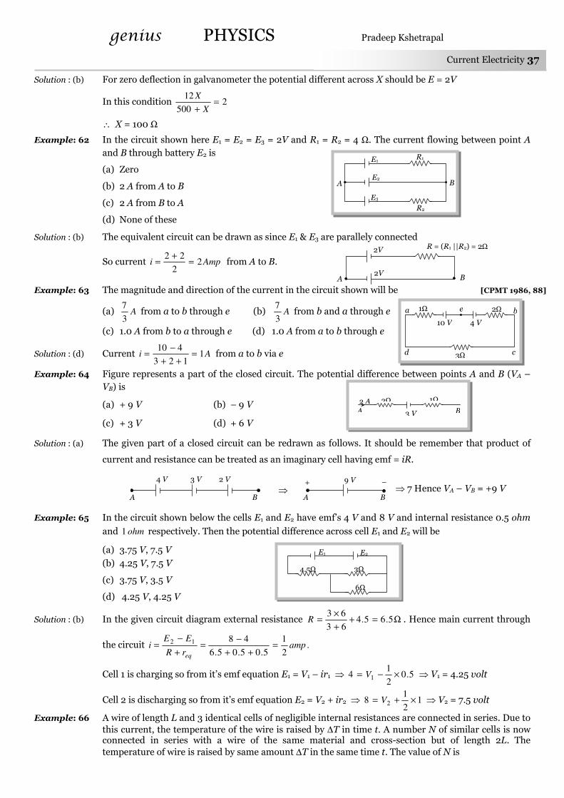
genius PHYSICS Pradeep Kshetrapal
Current Electricity 37
Solution : (b) For zero deflection in galvanometer the potential different across X should be E = 2V
In this condition 2500
12=
+ X
X
∴ X = 100 Ω
Example: 62 In the circuit shown here E1 = E2 = E3 = 2V and R1 = R2 = 4 Ω. The current flowing between point A
and B through battery E2 is
(a) Zero
(b) 2 A from A to B
(c) 2 A from B to A
(d) None of these
Solution : (b) The equivalent circuit can be drawn as since E1 & E3 are parallely connected
So current Ampi 22
22=
+= from A to B.
Example: 63 The magnitude and direction of the current in the circuit shown will be [CPMT 1986, 88]
(a) A3
7 from a to b through e (b) A
3
7 from b and a through e
(c) 1.0 A from b to a through e (d) 1.0 A from a to b through e
Solution : (d) Current Ai 1123
410=
++
−= from a to b via e
Example: 64 Figure represents a part of the closed circuit. The potential difference between points A and B (VA –
VB) is
(a) + 9 V (b) – 9 V
(c) + 3 V (d) + 6 V
Solution : (a) The given part of a closed circuit can be redrawn as follows. It should be remember that product of
current and resistance can be treated as an imaginary cell having emf = iR.
⇒ 7 Hence VA – VB = +9 V
Example: 65 In the circuit shown below the cells E1 and E2 have emf’s 4 V and 8 V and internal resistance 0.5 ohm
and ohm1 respectively. Then the potential difference across cell E1 and E2 will be
(a) 3.75 V, 7.5 V
(b) 4.25 V, 7.5 V
(c) 3.75 V, 3.5 V
(d) 4.25 V, 4.25 V
Solution : (b) In the given circuit diagram external resistance Ω=++
×= 5.65.4
63
63R . Hence main current through
the circuit .2
1
5.05.05.6
4812 amprR
EEi
eq
=++
−=
+
−=
Cell 1 is charging so from it’s emf equation E1 = V1 – ir1 ⇒ 5.02
14 1 ×−= V ⇒ V1 = 4.25 volt
Cell 2 is discharging so from it’s emf equation E2 = V2 + ir2 ⇒ 12
18 2 ×+= V ⇒ V2 = 7.5 volt
Example: 66 A wire of length L and 3 identical cells of negligible internal resistances are connected in series. Due to
this current, the temperature of the wire is raised by ∆T in time t. A number N of similar cells is now connected in series with a wire of the same material and cross-section but of length 2L. The
temperature of wire is raised by same amount ∆T in the same time t. The value of N is
R = (R1 ||R2) = 2Ω
B A 2V
2V
3 V
1Ω 2Ω 2 A
A B
3 V 2 V 4 V
A B ⇒
9 V
A B
+ –
R1
R2
B A
E1
E2
E3
10 V
a
c d
2Ω
3Ω
1Ω
4 V
e b
E1 E2
4.5Ω 3Ω
6Ω

genius PHYSICS Pradeep Kshetrapal
38 Current Electricity
(a) 4 (b) 6 (c) 8 (d) 9
Solution : (b) Heat = mS∆T = i2Rt
Case I : Length (L) ⇒ Resistance = R and mass = m Case II : Length (2L) ⇒ Resistance = 2R and mass = 2m
So 22
22
1121
222
111
tri
tRi
TSm
TSm=
∆
∆ ⇒
Rti
Rti
TmS
TmS
22 22
21=
∆
∆ ⇒ 21 ii = ⇒
R
NEE
2
)(
12
)3( 22
= ⇒ N = 6
n identical cells, each of emf E and internal resistance r, are joined in series to form a closed circuit. The potential difference across any one cell is
(a) Zero (b) E (c) n
E (d) E
n
n
− 1
Solution: (a) Current in the circuit r
E
nr
nEi ==
The equivalent circuit of one cell is shown in the figure. Potential difference across the cell
0. =+−=+−=−= rr
EEirEVV BA
Kirchoff’s Laws.
(1) Kirchoff’s first law : This law is also known as junction rule or current law (KCL). According to it
the algebraic sum of currents meeting at a junction is zero i.e. ∑∑∑∑i = 0.
In a circuit, at any junction the sum of the currents entering the junction must equal the sum of the currents leaving the junction. 4231 iiii +=+
Here it is worthy to note that :
(i) If a current comes out to be negative, actual direction of current at the junction is opposite to that assumed, 021 =++ iii can be satisfied only if at least
one current is negative, i.e. leaving the junction.
(ii) This law is simply a statement of “conservation of charge” as if current reaching a junction is not
equal to the current leaving the junction, charge will not be conserved.
Note : This law is also applicable to a capacitor through the concept of displacement current treating the
resistance of capacitor to be zero during charging or discharging and infinite in steady state as
shown in figure.
(2) Kirchoff’s second law : This law is also known as loop rule or voltage law (KVL) and according
to it “the algebraic sum of the changes in potential in complete traversal of a mesh (closed loop) is zero”, i.e.
∑∑∑∑V = 0
e.g. In the following closed loop.
– i1R1 + i2R2 – E1 – i3R3 + E2 + E3 – i4R4 = 0
i = i2
Steady state
R
C
i2
–
+
i1 = 0
i
(C)
i1 = i + i2
Discharging
R
C
i2
–
+
i1
i
(B)
i = i1 + i2
Charging
R
C
i2
–
+
i1
i
(A)
A B
– +
E r
i
Tricky Example: 8
+ –
R3
D
R2 B C
A
i4
i1 i2
E2 E3
R4
R1 E1 –
+
i3
i1
i2 i3
i4

genius PHYSICS Pradeep Kshetrapal
Current Electricity 39
Here it is worthy to note that :
(i) This law represents “conservation of energy” as if the sum of potential changes around a closed
loop is not zero, unlimited energy could be gained by repeatedly carrying a charge around a loop.
(ii) If there are n meshes in a circuit, the number of independent equations in accordance with loop rule will
be (n – 1).
(3) Sign convention for the application of Kirchoff’s law : For the application of Kirchoff’s
laws following sign convention are to be considered
(i) The change in potential in traversing a resistance in the direction of current is – iR while in the
opposite direction +iR
(ii) The change in potential in traversing an emf source from negative to positive terminal is +E while
in the opposite direction – E irrespective of the direction of current in the circuit.
(iii) The change in potential in traversing a capacitor from the negative terminal to the positive
terminal is C
q+ while in opposite direction
C
q− .
(iv) The change in voltage in traversing an inductor in the direction of current is dt
diL− while in
opposite direction it is dt
diL+ .
(4) Guidelines to apply Kirchoff’s law
(i) Starting from the positive terminal of the battery having highest emf, distribute current at various
junctions in the circuit in accordance with ‘junction rule’. It is not always easy to correctly guess the
direction of current, no problem if one assumes the wrong direction.
(ii) After assuming current in each branch, we pick a point and begin to walk (mentally) around a
closed loop. As we traverse each resistor, capacitor, inductor or battery we must write down, the voltage
change for that element according to the above sign convention.
(iii) By applying KVL we get one equation but in order to solve the circuit we require as many equations
as there are unknowns. So we select the required number of loops and apply Kirchhoff’s voltage law across
each such loop.
R i A B
– iR
R i A B
+ iR
E i A B
– E
E i A B
+ E
C A B
C
q+
+ –
q
C A B
C
q−
+ –
q
L i A B
dt
diL−
L i A B
dt
diL+

genius PHYSICS Pradeep Kshetrapal
40 Current Electricity
(iv) After solving the set of simultaneous equations, we obtain the numerical values of the assumed currents. If any of these values come out to be negative, it indicates that particular current is in the opposite direction from the assumed one.
Note : The number of loops must be selected so that every element of the circuit must be included in at least one of the loops.
While traversing through a capacitor or battery we do not consider the direction of current.
While considering the voltage drop or gain across as inductor we always assume current to be in increasing function.
(5) Determination of equivalent resistance by Kirchoff’s method : This method is useful when we are not able to identify any two resistances in series or in parallel. It is based on the two Kirchhoff’s laws. The method may be described in the following guideline.
(i) Assume an imaginary battery of emf E connected between the two terminals across which we have to calculate the equivalent resistance.
(ii) Assume some value of current, say i, coming out of the battery and distribute it among each branch by applying Kirchhoff’s current law.
(iii) Apply Kirchhoff’s voltage law to formulate as many equations as there are unknowns. It should be noted that at least one of the equations must include the assumed battery.
(iv) Solve the equations to determine i
E ratio which is the equivalent resistance of the network.
e.g. Suppose in the following network of 12 identical resistances, equivalent resistance between point A and C is to be calculated.
According to the above guidelines we can solve this problem as follows
Step (1)
Step (2)
An imaginary battery of emf E is assumed across the terminals A and C
The current in each branch is distributed by assuming 4i current coming out of the battery.
Step (3) Applying KVL along the loop including the nodes A, B, C and the battery E. Voltage equation
is 022 =+−−−− EiRiRiRiR
Step (4) After solving the above equation, we get 6iR = E ⇒ equivalent resistance between A and C is
Ri
iR
i
ER
2
3
4
6
4===
R
R
R
R
R
R R
R
R R
R
R
B
A C
D
E F
H G
R
R
R
R
R
R R
R R R
R R
B
A C
D
E F
H G
E
R
R
R
R
R
R R
R R R
R R
B
A C
D
E F
H G
E
4i 4i
2i i
i
2i
2i
i 2i
i
i i
i
i

genius PHYSICS Pradeep Kshetrapal
Current Electricity 41
Concepts
Using Kirchoff’s law while dividing the current having a junction through different arms of a network, it will be same
through different arms of same resistance if the end points of these arms are equilocated w.r.t. exit point for current in
network and will be different through different arms if the end point of these arms are not equilocated w.r.t. exit point
for current of the network.
e.g. In the following figure the current going in arms AB, AD and AL will be same because the location of end points B, D
and L of these arms are symmetrically located w.r.t. exit point N of the network.
Example: 67 In the following circuit E1 = 4V, R1 = 2Ω [MP PET 2003]
E2 = 6V, R2 = 2Ω and R3 = 4Ω. The current i1 is
(a) 1.6 A
(b) 1.8 A
(c) 2.25 A
(d) 1 A
Solution : (b) For loop (1) 04)(22 211 =+−−− iii ⇒ 22 21 =− ii …… (i)
For loop (2) 06)(24 212 =+−+− iii ⇒ 33 12 =− ii …… (ii)
After solving equation (i) and (ii) we get Ai 8.11 = and Ai 6.12 =
Example: 68 Determine the current in the following circuit
(a) 1 A
(b) 2.5 A
(c) 0.4 A
(d) 3 A
Solution : (a) Applying KVL in the given circuit we get 035102 =−−+− ii ⇒ Ai 1=
Second method : Similar plates of the two batteries are connected together, so the net emf = 10 – 5 = 5V
Total resistance in the circuit = 2 + 3 = 5Ω
∴ AR
Vi 1
5
5==
Σ
Σ=
Example: 69 In the circuit shown in figure, find the current through the branch BD
(a) 5 A (b) 0 A
(c) 3 A (d) 4 A
Solution : (a) The current in the circuit are assumed as shown in the fig.
Applying KVL along the loop ABDA, we get
– 6i1 – 3 i2 + 15 = 0 or 2i1 + i2 = 5 …… (i)
Applying KVL along the loop BCDB, we get
– 3(i1 – i2) – 30 + 3i2 = 0 or – i1 + 2i2 = 10 …… (ii)
Solving equation (i) and (ii) for i2, we get i2 = 5 A
Examples
E1 R1
R2
R3
E2
i2
i1
2Ω
i2
i1
i2
i1 (i1 – i2)
2Ω
4Ω
4V
6V
1
2
10 V 2Ω
3Ω 5 V
6Ω A C
15 V 3Ω
B
D
30 V
3Ω
A D
C
N
K L
B
M
6i
2i
2i
i
i
i i
2i i
2i
i
i
i
6i
6Ω A C
15 V 3Ω
B
D
30 V
3Ω i1 i1 – i2
i2
i1

genius PHYSICS Pradeep Kshetrapal
42 Current Electricity
Example: 70 The figure shows a network of currents. The magnitude of current is shown here. The current i will be [MP
PMT 1995]
(a) 3 A
(b) 13 A
(c) 23 A
(d) – 3 A
Solution : (c) Ai 235315 =++=
Example: 71 Consider the circuit shown in the figure. The current i3 is equal to [AMU 1995]
(a) 5 amp
(b) 3 amp
(c) – 3 amp
(d) – 5/6 amp
Solution : (d) Suppose current through different paths of the circuit is as follows.
After applying KVL for loop (1) and loop (2)
We get 8628 1 −−=i ⇒ Ai2
11 −=
and 12654 2 −−=i ⇒ Ai3
12 −=
Hence Aiii6
5213 −=+=
Example: 72 A part of a circuit in steady state along with the current flowing in the branches, with value of each resistance is shown in figure. What will be the energy stored in the capacitor C0
(a) 6 × 10⁻⁴ J
(b) 8 × 10⁻⁴ J
(c) 16 × 10–4 J
(d) Zero
Solution : (b) Applying Kirchhoff’s first law at junctions A and B respectively we have 2 + 1 – i1 = 0 i.e., i1 = 3A
and i2 + 1 – 2 – 0 = 0 i.e., i2 = 1A
Now applying Kirchhoff’s second law to the mesh ADCBA treating capacitor as a seat of emf V in open
circuit
– 3 × 5 – 3 × 1 – 1 × 2 + V = 0 i.e. V(= VA – VB) = 20 V
So, energy stored in the capacitor JCVU4262
108)20()104(2
1
2
1 −− ×=××==
Example: 73 In the following circuit the potential difference between P and Q is
(a) 15 V (b) 10 V
(c) 5 V (d) 2.5 V
Solution : (c) By using KVL 01525 =+−×− PQV ⇒ VPQ = 5V
15 A 3 A
5 A i
12 V
54Ω
i3
28Ω
6 V
8 V
12 V
54Ω
i3
28Ω
6 V
8 V
1 2
D
4µF 2A
5Ω
2A 2Ω 4Ω C
3Ω 1Ω
3Ω A
B
i3
i1
1A
3Ω
1Ω i2
1A
5Ω
R
2A
Q P
15V
E1 E2

genius PHYSICS Pradeep Kshetrapal
Current Electricity 43
As the switch S is closed in the circuit shown in figure, current passed through it is
(a) 4.5 A (b) 6.0 A (c) 3.0 A (d) Zero
Solution : (a) Let V be the potential of the junction as shown in figure. Applying junction law, we have
or 2
0
4
5
2
20 −=
−+
− VVV or 40 – 2V + 5 – V = 2V
or 5V = 45 ⇒ V = 9V
∴ AV
i 5.42
3 ==
Different Measuring Instruments.
(1) Galvanometer : It is an instrument used to detect small current passing through it by showing
deflection. Galvanometers are of different types e.g. moving coil galvanometer, moving magnet
galvanometer, hot wire galvanometer. In dc circuit usually moving coil galvanometer are used.
(i) It’s symbol : ; where G is the total internal resistance of the galvanometer.
(ii) Principle : In case of moving coil galvanometer deflection is directly proportional to the current
that passes through it i.e. θi ∝ .
(iii) Full scale deflection current : The current required for full scale deflection in a galvanometer
is called full scale deflection current and is represented by ig.
(iv) Shunt : The small resistance connected in parallel to galvanometer coil, in order to control
current flowing through the galvanometer is known as shunt.
Merits of shunt Demerits of shunt
(a) To protect the galvanometer
coil from burning
(b) It can be used to convert any
galvanometer into ammeter of
desired range.
Shunt resistance decreases the
sensitivity of galvanometer.
(2) Ammeter : It is a device used to measure current and is always connected in series with the
‘element’ through which current is to be measured.
(i) The reading of an ammeter is always lesser than actual current in the circuit.
(ii) Smaller the resistance of an ammeter more accurate will be its reading. An ammeter is said to be
ideal if its resistance r is zero.
(iii) Conversion of galvanometer into ammeter : A galvanometer may be converted into an
ammeter by connecting a low resistance (called shunt S) in parallel to the galvanometer G as shown in
figure.
(a) Equivalent resistance of the combination SG
GS
+=
Tricky Example: 9
G
4Ω 2Ω
B
S
2Ω
5 V
A
20 V
4Ω 2Ω
B
i3
2Ω
5 V
A
20 V
i1 i2
0 V
K S
G
S
i – ig i
ig
Ammeter
G

genius PHYSICS Pradeep Kshetrapal
44 Current Electricity
(b) G and S are parallel to each other hence both will have equal potential difference i.e. SiiGi gg )( −= ;
which gives
Required shunt Gii
iS
g
g
)( −=
(c) To pass nth part of main current (i.e. n
iig = ) through the galvanometer, required shunt
1)( −=
n
GS .
(3) Voltmeter : It is a device used to measure potential difference and is always put in parallel with
the ‘circuit element’ across which potential difference is to be measured.
(i) The reading of a voltmeter is always lesser than true value.
(ii) Greater the resistance of voltmeter, more accurate will be its
reading. A voltmeter is said to be ideal if its resistance is infinite, i.e., it draws
no current from the circuit element for its operation.
(iii) Conversion of galvanometer into voltmeter : A
galvanometer may be converted into a voltmeter by connecting a large resistance R in series with the
galvanometer as shown in the figure.
(a) Equivalent resistance of the combination = G + R
(b) According to ohm’s law V = ig (G + R); which gives
Required series resistance GV
VG
i
VR
gg
−=−= 1
(c) If nth part of applied voltage appeared across galvanometer (i.e. n
VVg = ) then required series
resistance GnR 1)( −= .
(4) Wheatstone bridge : Wheatstone bridge is an arrangement of four resistance which can be used
to measure one of them in terms of rest. Here arms AB and BC are called
ratio arm and arms AC and BD are called conjugate arms
(i) Balanced bridge : The bridge is said to be balanced when
deflection in galvanometer is zero i.e. no current flows through the
galvanometer or in other words VB = VD. In the balanced condition S
R
Q
P= ,
on mutually changing the position of cell and galvanometer this condition
will not change.
(ii) Unbalanced bridge : If the bridge is not balanced current will
flow from D to B if VD > VB i.e. )()( BADA VVVV −<− which gives PS > RQ.
(iii) Applications of wheatstone bridge : Meter bridge, post office
box and Carey Foster bridge are instruments based on the principle of
wheatstone bridge and are used to measure unknown resistance.
R
+ V –
i A
R
+ V –
i
V
R
ig
Vg = igG V – Vg
V
G
P Q
R S
+ –
A
B
C
D
G
K1
K2

genius PHYSICS Pradeep Kshetrapal
Current Electricity 45
(5) Meter bridge : In case of meter bridge, the resistance wire AC is 100 cm long. Varying the
position of tapping point B, bridge is balanced. If in balanced position of bridge AB = l, BC (100 – l) so that
l
l
P
Q )100( −= . Also
S
R
Q
P= ⇒ R
l
lS
)100( −=
Concepts
Wheatstone bridge is most sensitive if all the arms of bridge have equal resistances i.e. P = Q = R = S
If the temperature of the conductor placed in the right gap of metre bridge is increased, then the balancing length decreases and the jockey moves towards left.
In Wheatstone bridge to avoid inductive effects the battery key should be pressed first and the galvanometer key afterwards.
The measurement of resistance by Wheatstone bridge is not affected by the internal resistance of the cell.
Example: 74 The scale of a galvanometer of resistance 100 Ω contains 25 divisions. It gives a deflection of one
division on passing a current of 4 × 10⁻⁴ A. The resistance in ohms to be added to it, so that it may become a voltmeter of range 2.5 volt is
(a) 100 (b) 150 (c) 250 (d) 300
Solution : (b) Current sensitivity of galvanometer = 4 × 10⁻⁴ Amp/div.
So full scale deflection current (ig) = Current sensitivity × Total number of division = 4 × 10–4 × 25 = 10–2 A
To convert galvanometer in to voltmeter, resistance to be put in series is
Ω=−=−=−
15010010
5.22
Gi
VR
g
Example: 75 A galvanometer, having a resistance of 50 Ω gives a full scale deflection for a current of 0.05 A. the
length in meter of a resistance wire of area of cross-section 2.97 × 10⁻² cm2 that can be used to convert the galvanometer into an ammeter which can read a maximum of 5A current is : (Specific resistance of
the wire = 5 × 10⁻⁷ Ωm) [EAMCET 2003]
(a) 9 (b) 6 (c) 3 (d) 1.5
Solution : (c) Given G = 50 Ω, ig = 0.05 Amp., i = 5A, A = 2.97 × 10⁻² cm2 and ρ = 5 × 10⁻⁷Ω-m
By using S
G
i
i
g
+= 1 ⇒ ρ
ρ
)()()(
.
g
g
g
g
g
g
ii
AGil
ii
Gi
A
l
ii
iGS
−=⇒
−=⇒
−= on putting values l = 3 m.
Example: 76 100 mA current gives a full scale deflection in a galvanometer of resistance 2 Ω. The resistance connected with the galvanometer to convert it into a voltmeter of 5 V range is
[KCET 2002; UPSEAT 1998; MNR 1994 Similar to MP PMT 1999]
(a) 98 Ω (b) 52 Ω (c) 80 Ω (d) 48 Ω
Solution : (d) Ω=−=−×
=−=−
48250210100
53
GI
VR
g
.
Example: 77 A milliammeter of range 10 mA has a coil of resistance 1 Ω. To use it as voltmeter of range 10 volt, the
resistance that must be connected in series with it will be
(a) 999 Ω (b) 99 Ω (c) 1000 Ω (d) None of these
Examples
R.B.
G
R S
P Q
l cm (100 – l) cm
E K
A B C
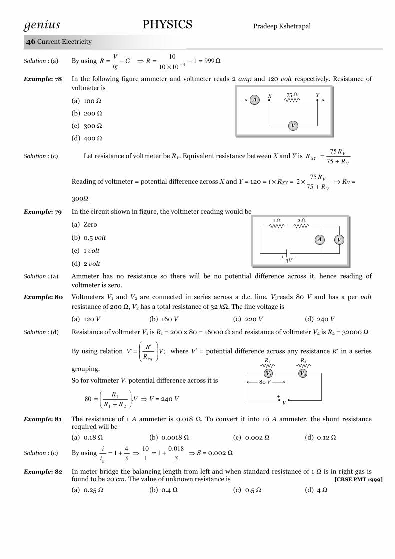
genius PHYSICS Pradeep Kshetrapal
46 Current Electricity
Solution : (a) By using Ω=−×
=⇒−=−
99911010
103
RGig
VR
Example: 78 In the following figure ammeter and voltmeter reads 2 amp and 120 volt respectively. Resistance of
voltmeter is
(a) 100 Ω
(b) 200 Ω
(c) 300 Ω
(d) 400 Ω
Solution : (c) Let resistance of voltmeter be RV. Equivalent resistance between X and Y is V
VXY
R
RR
+=
75
75
Reading of voltmeter = potential difference across X and Y = 120 = i × RXY = V
V
R
R
+×
75
752 ⇒ RV =
300Ω
Example: 79 In the circuit shown in figure, the voltmeter reading would be
(a) Zero
(b) 0.5 volt
(c) 1 volt
(d) 2 volt
Solution : (a) Ammeter has no resistance so there will be no potential difference across it, hence reading of
voltmeter is zero.
Example: 80 Voltmeters V1 and V2 are connected in series across a d.c. line. V1reads 80 V and has a per volt
resistance of 200 Ω, V2 has a total resistance of 32 kΩ. The line voltage is
(a) 120 V (b) 160 V (c) 220 V (d) 240 V
Solution : (d) Resistance of voltmeter V1 is R1 = 200 × 80 = 16000 Ω and resistance of voltmeter V2 is R2 = 32000 Ω
By using relation ;'
' VR
RV
eq
= where V′ = potential difference across any resistance R′ in a series
grouping.
So for voltmeter V1 potential difference across it is
VRR
R.80
21
1
+= ⇒ V = 240 V
Example: 81 The resistance of 1 A ammeter is 0.018 Ω. To convert it into 10 A ammeter, the shunt resistance required will be
(a) 0.18 Ω (b) 0.0018 Ω (c) 0.002 Ω (d) 0.12 Ω
Solution : (c) By using Si
i
g
41 += ⇒
S
018.01
1
10+= ⇒ S = 0.002 Ω
Example: 82 In meter bridge the balancing length from left and when standard resistance of 1 Ω is in right gas is found to be 20 cm. The value of unknown resistance is [CBSE PMT 1999]
(a) 0.25 Ω (b) 0.4 Ω (c) 0.5 Ω (d) 4 Ω
A
V
X Y 75 Ω
2 Ω
+ 3V –
V A
1 Ω
V1
R2
80 V
V
V2
R1
+ –

genius PHYSICS Pradeep Kshetrapal
Current Electricity 47
Solution: (a) The condition of wheatstone bridge gives ,80
20
r
r
R
X= r- resistance of wire per cm, X- unknown
resistance
∴ Ω=×=×= 25.014
1
80
20RX
Example: 83 A galvanometer having a resistance of 8 Ω is shunted by a wire of resistance 2 Ω. If the total current is
1 amp, the part of it passing through the shunt will be [CBSE PMT 1998]
(a) 0.25 amp (b) 0.8 amp (c) 0.2 amp (d) 0.5 amp
Solution: (b) Fraction of current passing through the galvanometer
GS
S
i
ig
+= or 2.0
82
2=
+=
i
ig
So fraction of current passing through the shunt
ampi
i
i
i gs 8.02.011 =−=−=
Example: 84 A moving coil galvanometer is converted into an ammeter reading upto 0.03 A by connecting a shunt of resistance 4r across it and into an ammeter reading upto 0.06 A when a shunt of resistance r connected across it. What is the maximum current which can be through this galvanometer if no shunt is used
[MP PMT 1996]
(a) 0.01 A (b) 0.02 A (c) 0.03 A (d) 0.04 A
Solution: (b) For ammeter, Gii
iS
g
g
)( −= ⇒ SiiGi gg )( −=
So riGi gg 4)03.0( −= …… (i) and riGi gg )06.0( −= …… (ii)
Dividing equation (i) by (ii) gg
g
gii
i
i412.006.0
06.0
4)03.0(1 −=−⇒
−
−=
⇒ 3ig = 0.06 ⇒ ig = 0.02 A
The ammeter A reads 2 A and the voltmeter V reads 20 V. The value of resistance R is
(a) Exactly 10 ohm (b) Less than 10 ohm
(c) More than 10 ohm (d) We cannot definitely say
Solution: (c) If current goes through the resistance R is i then iR = 20 volt ⇒i
R20
= . Since i < 2A so R >
10Ω.
Potentiometer.
Potentiometer is a device mainly used to measure emf of a given cell and to compare emf’s of cells. It is
also used to measure internal resistance of a given cell.
(1) Superiority of potentiometer over voltmeter : An ordinary voltmeter cannot measure the
emf accurately because it does draw some current to show the deflection. As per definition of emf, it is the
potential difference when a cell is in open circuit or no current through the cell. Therefore voltmeter can
only measure terminal voltage of a give n cell.
R
V
A
Tricky Example: 10
X R = 1Ω
Q = 80 r P = 20 r
20 cm 80 cm

genius PHYSICS Pradeep Kshetrapal
48 Current Electricity
Potentiometer is based on no deflection method. When the potentiometer gives zero deflection, it does
not draw any current from the cell or the circuit i.e. potentiometer is effectively an ideal instrument of
infinite resistance for measuring the potential difference.
(2) Circuit diagram : Potentiometer consists of a long resistive wire AB of length L (about 6m to 10
m long) made up of mangnine or constantan. A battery of known voltage e and internal resistance r called
supplier battery or driver cell. Connection of these two forms primary circuit.
One terminal of another cell (whose emf E is to be measured) is connected at one end of the main
circuit and the other terminal at any point on the resistive wire through a galvanometer G. This forms the
secondary circuit. Other details are as follows
J = Jockey
K = Key
R = Resistance of potentiometer wire,
ρ = Specific resistance of potentiometer wire.
Rh = Variable resistance which controls the current through the wire AB
(3) Points to be remember
(i) The specific resistance (ρ) of potentiometer wire must be high but its temperature coefficient of
resistance (α) must be low.
(ii) All higher potential points (terminals) of primary and secondary circuits must be connected
together at point A and all lower potential points must be connected to point B or jockey.
(iii) The value of known potential difference must be greater than the value of unknown potential
difference to be measured.
(iv) The potential gradient must remain constant. For this the current in the primary circuit must
remain constant and the jockey must not be slided in contact with the wire.
(v) The diameter of potentiometer wire must be uniform everywhere.
(4) Potential gradient (x) : Potential difference (or fall in potential) per unit length of wire is called
potential gradient i.e. m
volt
L
Vx = where R
rRR
eiRV
h
.
++== . So
L
R.
rRR
e
A
iρ
L
iR
L
Vx
h )( ++====
(i) Potential gradient directly depends upon
(a) The resistance per unit length (R/L) of potentiometer wire.
(b) The radius of potentiometer wire (i.e. Area of cross-section)
(c) The specific resistance of the material of potentiometer wire (i.e. ρ)
(d) The current flowing through potentiometer wire (i)
(ii) x indirectly depends upon
(a) The emf of battery in the primary circuit (i.e. e)
(b) The resistance of rheostat in the primary circuit (i.e. Rh)
Note : When potential difference V is constant then 1
2
2
1
L
L
x
x=
Two different wire are connected in series to form a potentiometer wire then 1
2
2
1
2
1 .L
L
R
R
x
x=
If the length of a potentiometer wire and potential difference across it’s ends are kept
constant and if it’s diameter is changed from d1 → d2 then potential gradient remains unchanged.
A
Rh K
B
e, r
Primary circuit
Secondary circuit
J
E G

genius PHYSICS Pradeep Kshetrapal
Current Electricity 49
The value of x does not change with any change effected in the secondary circuit.
(5) Working : Suppose jocky is made to touch a point J on wire then potential difference between A
and J will be xlV =
At this length (l) two potential difference are obtained
(i) V due to battery e and
(ii) E due to unknown cell
If V > E then current will flow in galvanometer circuit in one direction
If V < E then current will flow in galvanometer circuit in opposite direction
If V = E then no current will flow in galvanometer circuit this condition to known as null deflection
position, length l is known as balancing length.
In balanced condition xlE = or lL
R.
rRR
el
L
iRl
L
VxlE
h
×
++====
Note : If V is constant then L ∝ l ⇒ 2
1
2
1
l
l
L
L=
(6) Standardization of potentiometer : The process of determining potential gradient
experimentally is known as standardization of potentiometer.
Let the balancing length for the standard emf E0 is l0 then by the
principle of potentiometer E0 = xl0 ⇒ 0
0
l
Ex =
(7) Sensitivity of potentiometer : A potentiometer is said to be
more sensitive, if it measures a small potential difference more
accurately.
(i) The sensitivity of potentiometer is assessed by its potential
gradient. The sensitivity is inversely proportional to the potential gradient.
(ii) In order to increase the sensitivity of potentiometer
(a) The resistance in primary circuit will have to be decreased.
(b) The length of potentiometer wire will have to be increased so that the length may be measured more
accuracy.
(8) Difference between voltmeter and potentiometer
Voltmeter Potentiometer
(i) It’s resistance is high but finite Its resistance is high but infinite
(ii) It draws some current from source of emf It does not draw any current from the source of known
emf
(iii
)
The potential difference measured by it is lesser
than the actual potential difference
The potential difference measured by it is equal to
actual potential difference
(iv) Its sensitivity is low Its sensitivity is high
(v) It is a versatile instrument It measures only emf or potential difference
(vi) It is based on deflection method It is based on zero deflection method
E0
A
Rh K
B
e, r
J
G
E
E
A
Rh K
B
e, r
l J J2 J1
G G G

genius PHYSICS Pradeep Kshetrapal
50 Current Electricity
Application of Potentiometer.
(1) To determine the internal resistance of a primary cell
(i) Initially in secondary circuit key K' remains open and balancing length (l1) is obtained. Since cell E
is in open circuit so it’s emf balances on length l1 i.e. E = xl1 ……. (i)
(ii) Now key K′ is closed so cell E comes in closed circuit. If the
process is repeated again then potential difference V balances on
length l2 i.e. V = xl2 ……. (ii)
(iii) By using formula internal resistance '.1 RV
Er
−=
'.2
21 Rl
llr
−=
(2) Comparison of emf’s of two cell : Let l1 and l2 be the balancing lengths with the cells E1 and E2
respectively then E1 = xl1 and E2 = xl2 ⇒ 2
1
2
1
l
l
E
E=
Note : Let E1 > E2 and both are connected in series. If
balancing length is l1 when cell assist each other and it is
l2 when they oppose each other as shown then :
121 )( xlEE =+ 221 )( xlEE =−
⇒ 2
1
21
21
l
l
EE
EE=
−
+ or
21
21
2
1
ll
ll
E
E
−
+=
(3) Comparison of resistances : Let the balancing length for resistance R1 (when XY is connected)
is l1 and let balancing length for resistance R1 + R2 (when YZ is connected) is
l2. Then iR1 = xl1 and i(R1 + R2) = xl2
⇒ 1
12
1
2
l
ll
R
R −=
(4) To determine thermo emf
(i) The value of thermo-emf in a thermocouple for ordinary temperature difference is very low (10–6
volt). For this the potential gradient x must be also very low (10–4 V/m).
Hence a high resistance (R) is connected in series with the potentiometer
wire in order to reduce current.
(ii) The potential difference across R must be equal to the emf of
standard cell i.e. iR = E0 ∴ R
Ei 0=
(iii) The small thermo emf produced in the thermocouple e = xl
E
A
Rh K
B J
K′ R′
G
e, r
+ – + – E1 E2
+ – – + E1 E2
A
RK
B J
1hRK1
R1 R
G X Y Z
i
A
K + –
B
+ –
Rh
1 2 3
R A
E0 G
G
Cold ice Hot sand
HRB
E1
A
Rh K
B
e, r
J
G
E2
1
2

genius PHYSICS Pradeep Kshetrapal
Current Electricity 51
(iv) L
iRix == ρ ∴
L
iRle = where L = length of potentiometer wire, ρ = resistance per unit length, l
= balancing length for e
(5) To calibrate ammeter and voltmeter
Calibration of ammeter
(i) If p.d. across 1Ω resistance is measured by potentiometer, then current through this (indirectly measured) is
thus known or if R is known then i = V/R can be found.
(ii) Circuit and method
(a) Standardisation is required and per formed as already described earlier. (x = E0/l0)
(b) The current through R or 1Ω coil is measured by the connected
ammeter and same is calculated by potentiometer by finding a
balancing length as described blow.
Let 'i current flows through 1Ω resistance giving p.d. as 1)1('' xliV ==
where l1 is the balancing length. So error can be found as [i (measured
by ammeter)
==−=∆ 1
0
01'' l
l
Exliii
Calibration of voltmeter
(i) Practical voltmeters are not ideal, because these do not have infinite resistance. The error of such practical
voltmeter can be found by comparing the voltmeter reading with calculated value of p.d. by potentiometer.
(ii) Circuit and procedure
(a) Standardisation : If l0 is balancing length for E0 the emf of
standard cell by connecting 1 and 2 of bi-directional key, then x = E0/l0.
(b) The balancing length l1 for unknown potential difference V′ is given
by (by closing 2 and 3) 1001 )/(' llExlV == .
If the voltmeter reading is V then the error will be (V – V′) which
may be +ve, – ve or zero.
Concepts
In case of zero deflection in the galvanometer current flows in the primary circuit of the potentiometer, not in the
galvanometer circuit.
A potentiometer can act as an ideal voltmeter.
Example: 85 A battery with negligible internal resistance is connected with 10m long wire. A standard cell gets
balanced on 600 cm length of this wire. On increasing the length of potentiometer wire by 2m then
the null point will be displaced by
(a) 200 cm (b) 120 cm (c) 720 cm (d) 600 cm
Solution : (b) By using 2
1
2
1
l
l
L
L= ⇒
2
600
12
10
l= ⇒ cml 7202 = .
Hence displacement = 720 – 600 = 120 cm
E1 + – 1
A
G
e K1
+ –
+
2
B
3 1Ω
+ – K2
A + –
E0 + – 1
A
G
e K1
+ –
+
2
B
3 RB
+ – K2
Rh
C
V + –
Rh
Examples

genius PHYSICS Pradeep Kshetrapal
52 Current Electricity
Example: 86 In the following circuit a 10 m long potentiometer wire with resistance 1.2 ohm/m, a resistance R1 and
an accumulator of emf 2 V are connected in series. When the emf of thermocouple is 2.4 mV then the
deflection in galvanometer is zero. The current supplied by the accumulator will be
(a) 4 × 10⁻⁴ A (b) 8 × 10⁻⁴ A (c) 4 × 10⁻³ A (d) 8 × 10⁻³ A
Solution : (a) lilxE ρ== ∴ Al
E
l
Ei 4
3
10452.1
104.2 −−
×=×
×===
ρρ.
Example: 87 The resistivity of a potentiometer wire is 40 × 10–8 Ωm and its area of cross section is 8 × 10⁻⁶ m2.
If 0.2 amp. Current is flowing through the wire, the potential gradient will be
(a) 10–2 volt/m (b) 10–1 volt/m (c) 3.2 × 10⁻² volt/m (d) 1 volt/m
Solution : (a) Potential gradient A
i
AL
Li
L
iR
L
V ρρ==== mV/10
108
10402.0 2
6
8−
−
−
=×
××=
Example: 88 A deniel cell is balanced on 125 cm length of a potentiometer wire. When the cell is short circuited
with a 2 Ω resistance the balancing length obtained is 100 cm. Internal resistance of the cell will
be [RPMT 1998]
(a) 1.5 Ω (b) 0.5 Ω (c) 1.25 Ω (d) 4/5 Ω
Solution: (b) By using Ω==×−
=⇒×−
= 5.02
12
100
100125'
2
21 rRl
llr
Example: 89 A potentiometer wire of length 10 m and a resistance 30 Ω is connected in series with a battery of
emf 2.5 V and internal resistance 5 Ω and an external resistance R. If the fall of potential along
the potentiometer wire is 50 µV/mm, the value of R is (in Ω)
(a) 115 (b) 80 (c) 50 (d) 100
Solution : (a) By using L
R
rRR
ex
h
.)( ++
=
⇒ 10
30
)530(
5.2
10
10503
6
×++
=×
−
−
R ⇒ R = 115
Example: 90 A 2 volt battery, a 15 Ω resistor and a potentiometer of 100 cm length, all are connected in series. If
the resistance of potentiometer wire is 5 Ω, then the potential gradient of the potentiometer wire is [AIIMS 1982]
(a) 0.005 V/cm (b) 0.05 V/cm (c) 0.02 V/cm (d) 0.2 V/cm
Solution : (a) By using L
R
rRR
ex
h
.)( ++
= ⇒ cmVmVx /005.0/5.01
5
)0155(
2==×
++=
Example: 91 In an experiment to measure the internal resistance of a cell by potentiometer, it is found that the
balance point is at a length of 2 m when the cell is shunted by a 5 Ω resistance; and is at a length of 3
m when the cell is shunted by a 10 Ω resistance. The internal resistance of the cell is, then
i
B
+ – R1
Cold Junction
Hot Junction
A 5 m
G

genius PHYSICS Pradeep Kshetrapal
Current Electricity 53
(a) 1.5 Ω (b) 10 Ω (c) 15 Ω (d) 1 Ω
Solution : (b) By using '2
21 Rl
llr
−= ⇒ 5
2
21 ×
−=
lr …… (i)
and 103
31 ×
−=
lr ……. (ii)
On solving (i) and (ii) r = 10 Ω
Example: 92 A resistance of 4 Ω and a wire of length 5 metres and resistance 5 Ω are joined in series and connected
to a cell of emf 10 V and internal resistance 1 Ω. A parallel combination of two identical cells is
balanced across 300 cm of the wire. The emf E of each cell is
(a) 1.5 V (b) 3.0 V (c) 0.67 V (d) 1.33 V
Solution : (b) By using lL
R
rRR
eE
h
eq ×++
= .)(
⇒ 35
5
)145(
10××
++=E ⇒ E = 3 volt
Example: 93 A potentiometer has uniform potential gradient across it. Two cells connected in series (i) to support
each other and (ii) to oppose each other are balanced over 6 m and 2 m respectively on the
potentiometer wire. The emf’s of the cells are in the ratio of [MP PMT 2002; RPMT 2000]
(a) 1 : 2 (b) 1 : 1 (c) 3 : 1 (d) 2 : 1
Solution : (d) If suppose emf’s of the cells are E1 and E2 respectively then
E1 + E2 = x × 6 ……. (i) [x = potential gradient) ]
and E1 – E2 = x × 2 …….(ii)
⇒ 1
3
21
21 =−
+
EE
EE ⇒
1
2
2
1 =E
E
Example: 94 In the following circuit the potential difference between the points B and C is balanced against 40 cm
length of potentiometer wire. In order to balance the potential difference between the points C and D,
where should jockey be pressed
(a) 32 cm (b) 16 cm (c) 8 cm (d) 4 cm
Solution : (a) 5
1
10
2
10
1
10
11==+=
R or R1 = 5 Ω
R2 = 4Ω, l1 = 40 cm, l2 = ? 1
212
R
Rll = or cml 32
5
4402 =
×=
E
G
5m
4Ω
E
10 V, 1Ω
5Ω
3m
X
G
+ –
Y
+ –
Rh
D
K
B
A 6V
10 Ω
10 Ω
40 cm
r = 1Ω F
C 4 Ω

genius PHYSICS Pradeep Kshetrapal
54 Current Electricity
Example: 95 In the following circuit diagram fig. the lengths of the wires AB and BC are same but the radius of AB
is three times that of BC. The ratio of potential gradients at AB and BC will be
(a) 1 : 9
(b) 9 : 1
(c) 3 : 1
(d) 1 : 3
Solution : (a) 2
1
rRx p ∝∝ ⇒
9
1
3
2
21
22
2
1 =
==
r
r
r
r
x
x
Example: 96 With a certain cell the balance point is obtained at 0.60 m from one end of the potentiometer. With
another cell whose emf differs from that of the first by 0.1 V, the balance point is obtained at 0.55 m.
Then, the two emf’s are
(a) 1.2 V, 1.1 V (b) 1.2 V, 1.3 V (c) – 1.1 V, – 1.0 V (d) None of the above
Solution : (a) E1 = x (0.6) and E2 = E1 – 0.1 = x (0.55) ⇒ 55.0
6.0
1.01
1 =−E
E
or 55 E1 = 60 E1 – 6 ⇒ VE 2.15
61 == thus E2 = 1.1 V
A cell of internal resistance 1.5Ω and of emf 1.5 volt balances 500 cm on a potentiometer wire. If a
wire of 15Ω is connected between the balance point and the cell, then the balance point will shift
[MP PMT 1985]
(a) To zero (b) By 500 cm
(c) By 750 cm (d) None of the above
Solution : (d) In balance condition no current flows in the galvanometer circuit. Hence there will be no shift in
balance point after connecting a resistance between balance point and cell.
Tricky Example: 11
C B A
+ –

genius PHYSICS Pradeep Kshetrapal
Current Electricity 55
.