practical temperature measurements 001 agilent technologies classroom series
TRANSCRIPT
Practical Temperature Measurements
001
Agilent Technologies Classroom Series
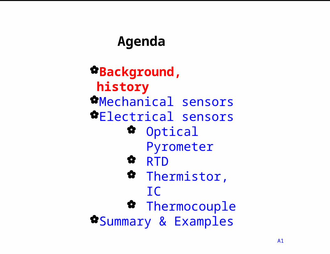
Agenda
A1
Background, history
Mechanical sensorsElectrical sensors
Optical Pyrometer
RTD Thermistor, IC Thermocouple
Summary & Examples
What is Temperature?
A scalar quantity that determines the direction of heat flow between two bodies
A statistical measurementA difficult measurementA mostly empirical measurement
002

How is heat transferred?
003
Conduction
Convection
Radiation
Metal coffee cup
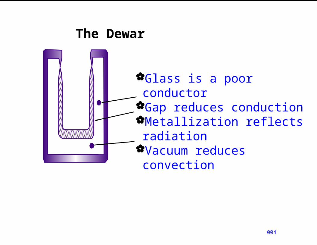
The Dewar
004
Glass is a poor conductorGap reduces conductionMetallization reflects radiation
Vacuum reduces convection
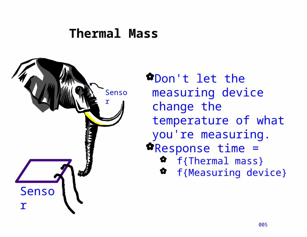
Thermal Mass
005
Sensor
Sensor
Don't let the measuring device change the temperature of what you're measuring.
Response time = f{Thermal mass} f{Measuring device}

Temperature errors
006
97.6 98.6 99.6 36.5 37 37.5
What is YOUR normal temperature?Thermometer accuracy, resolutionContact timeThermal mass of thermometer, tongue
Human error in reading
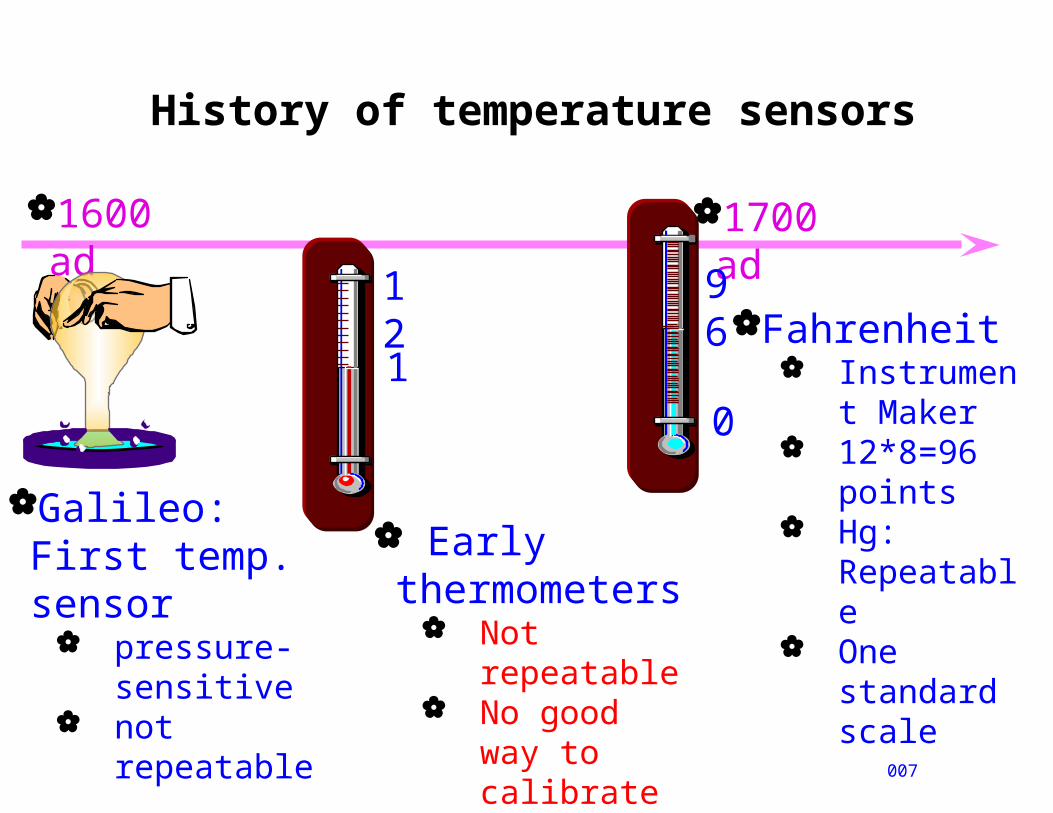
History of temperature sensors
007
1600 ad
1700 ad
Galileo: First temp. sensor
pressure-sensitive
not repeatable
Early thermometers
Not repeatable
No good way to calibrate
121
0
96Fahrenheit
Instrument Maker
12*8=96 points
Hg: Repeatable
One standard scale
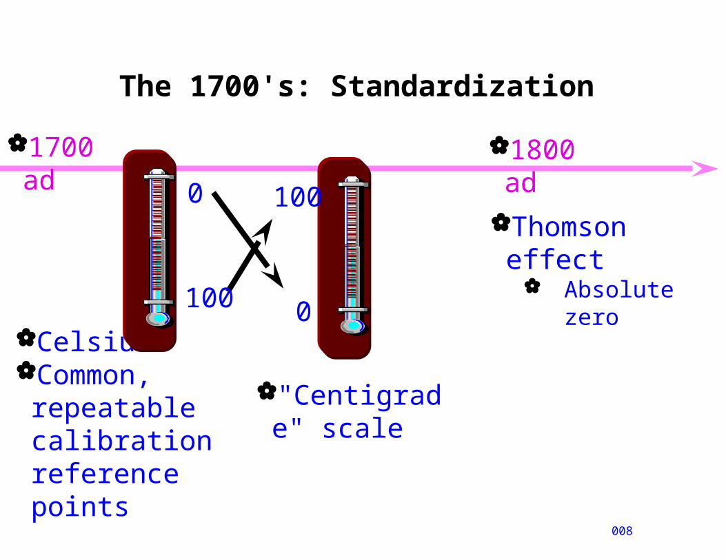
The 1700's: Standardization
008
1700 ad 1800 ad
Celsius:Common, repeatable calibration reference points
Thomson effect
Absolute zero
0
100
0
100
"Centigrade" scale
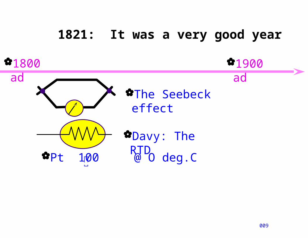
1821: It was a very good year
009
1800 ad 1900 ad
The Seebeck effect
Pt 100 @ O deg.C
Davy: The RTD
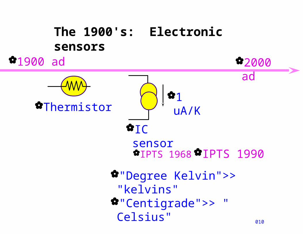
The 1900's: Electronic sensors
010
1900 ad
Thermistor
2000 ad
1 uA/K
IC sensor
IPTS 1968
"Degree Kelvin">> "kelvins"
"Centigrade">> " Celsius"
IPTS 1990
Temperature scales
011
-273.15
Absolute zero
0
-459.67
0
Celsius
Kelvin
Fahrenheit
Rankine
0
273.1532427.67
100373.15212
671.67
Freezing point H O2
Boiling point H O2
"Standard" is "better": Reliable reference
points Easy to understand
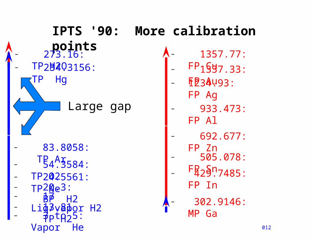
IPTS '90: More calibration points
012
– 273.16: TP H2O
– 83.8058: TP Ar– 54.3584: TP O2– 24.5561: TP Ne– 20.3: BP H2– 17 Liq/vapor H2 – 13.81 TP H2
Large gap
– 1234.93: FP Ag
– 1337.33: FP Au
– 692.677: FP Zn
– 429.7485: FP In
– 234.3156: TP Hg
– 302.9146: MP Ga
– 505.078: FP Sn
– 933.473: FP Al
– 1357.77: FP Cu
– 3 to 5: Vapor He
Agenda
A2
Background, historyMechanical sensors
Electrical sensors Optical
Pyrometer RTD Thermistor, IC Thermocouple
Summary & Examples
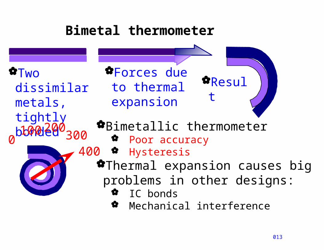
Bimetal thermometer
013
Two dissimilar metals, tightly bonded
Forces due to thermal expansion
Result
Bimetallic thermometer Poor accuracy Hysteresis
Thermal expansion causes big problems in other designs:
IC bonds Mechanical interference
0100
300
200
400
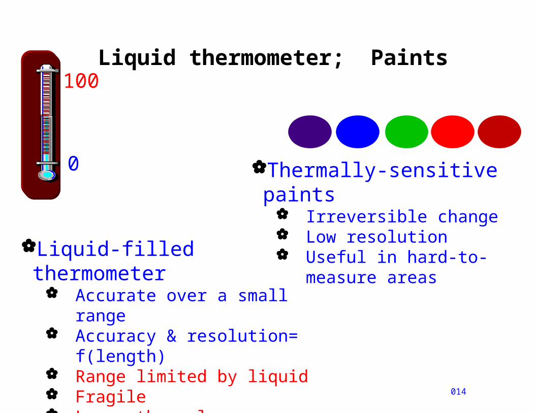
Liquid thermometer; Paints
014
0
100
Liquid-filled thermometer Accurate over a small range Accuracy & resolution=
f(length) Range limited by liquid Fragile Large thermal mass Slow
Thermally-sensitive paints Irreversible change Low resolution Useful in hard-to-measure
areas
Agenda
A3
Background, historyMechanical sensorsElectrical sensors
Optical Pyrometer
RTD Thermistor, IC Thermocouple
Summary & Examples
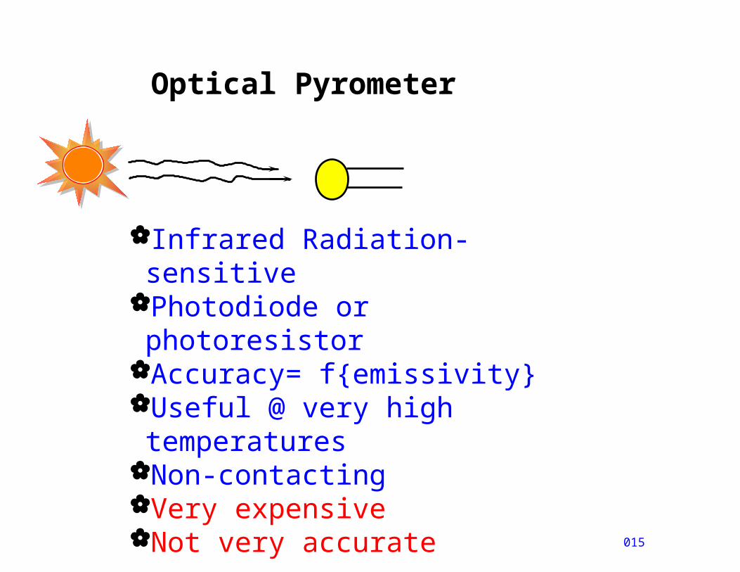
Optical Pyrometer
015
Infrared Radiation-sensitivePhotodiode or photoresistorAccuracy= f{emissivity}Useful @ very high temperatures
Non-contactingVery expensiveNot very accurate
Agenda
A4
Background, historyMechanical sensorsElectrical sensors
Optical Pyrometer
RTD Thermistor, IC Thermocouple
Summary & Examples
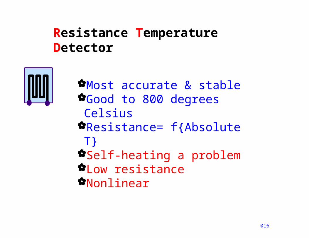
Resistance Temperature Detector
016
Most accurate & stableGood to 800 degrees Celsius
Resistance= f{Absolute T}Self-heating a problemLow resistanceNonlinear
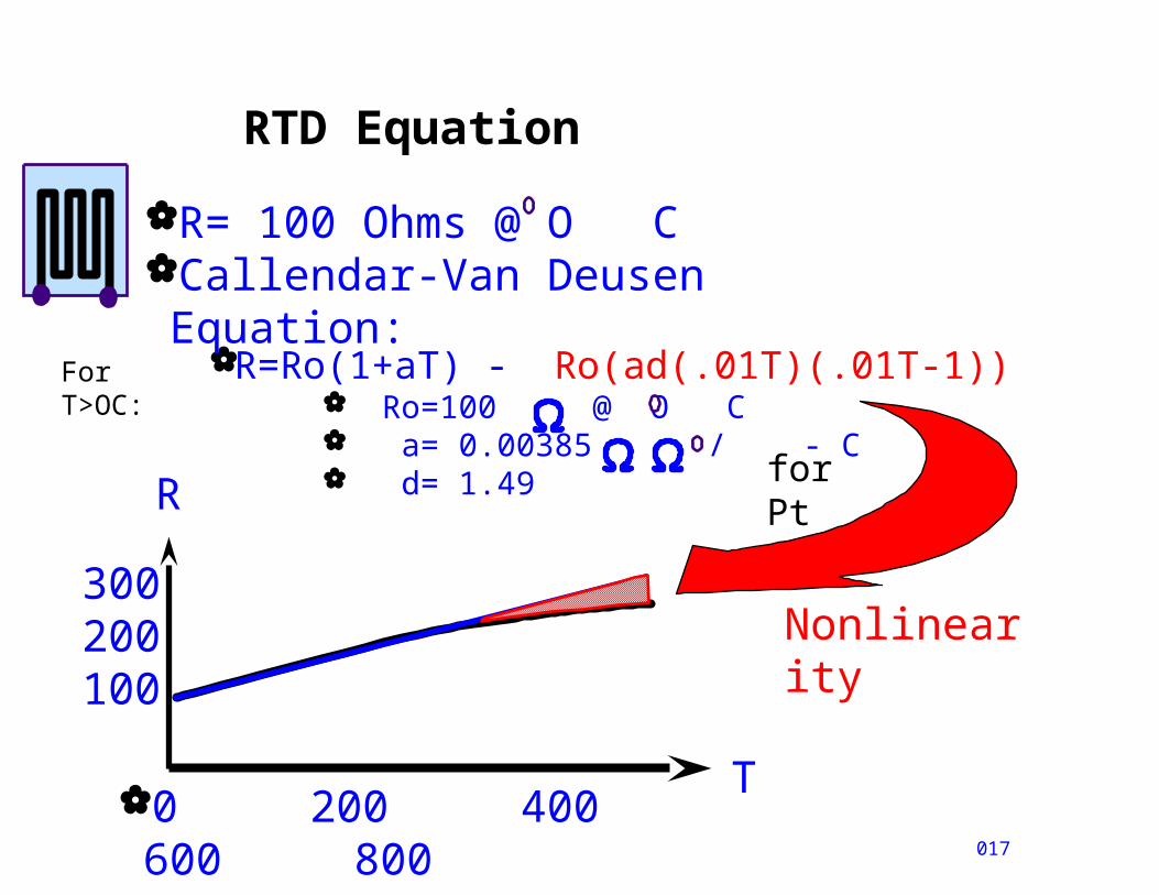
RTD Equation
R=Ro(1+aT) - Ro(ad(.01T)(.01T-1)) Ro=100 @ O C a= 0.00385 / - C d= 1.49
017
R= 100 Ohms @ O CCallendar-Van Deusen Equation:
0 200 400 600 800
R
T
300200100
Nonlinearity
For T>OC:
for Pt

Measuring an RTD: 2-wire method
018
R= Iref*(Rx + 2* Rlead) Error= 2 /.385= more than 5 degrees C for 1
ohm Rlead!Self-heating:
For 0.5 V signal, I= 5mA; P=.5*.005=2.5 mwatts
@ 1 mW/deg C, Error = 2.5 deg C!Moral: Minimize Iref; Use 4-wire method
If you must use 2-wire, NULL out the lead resistance
100
Rlead
V-
+I ref= 5 mA
Pt
Rx
Rlead
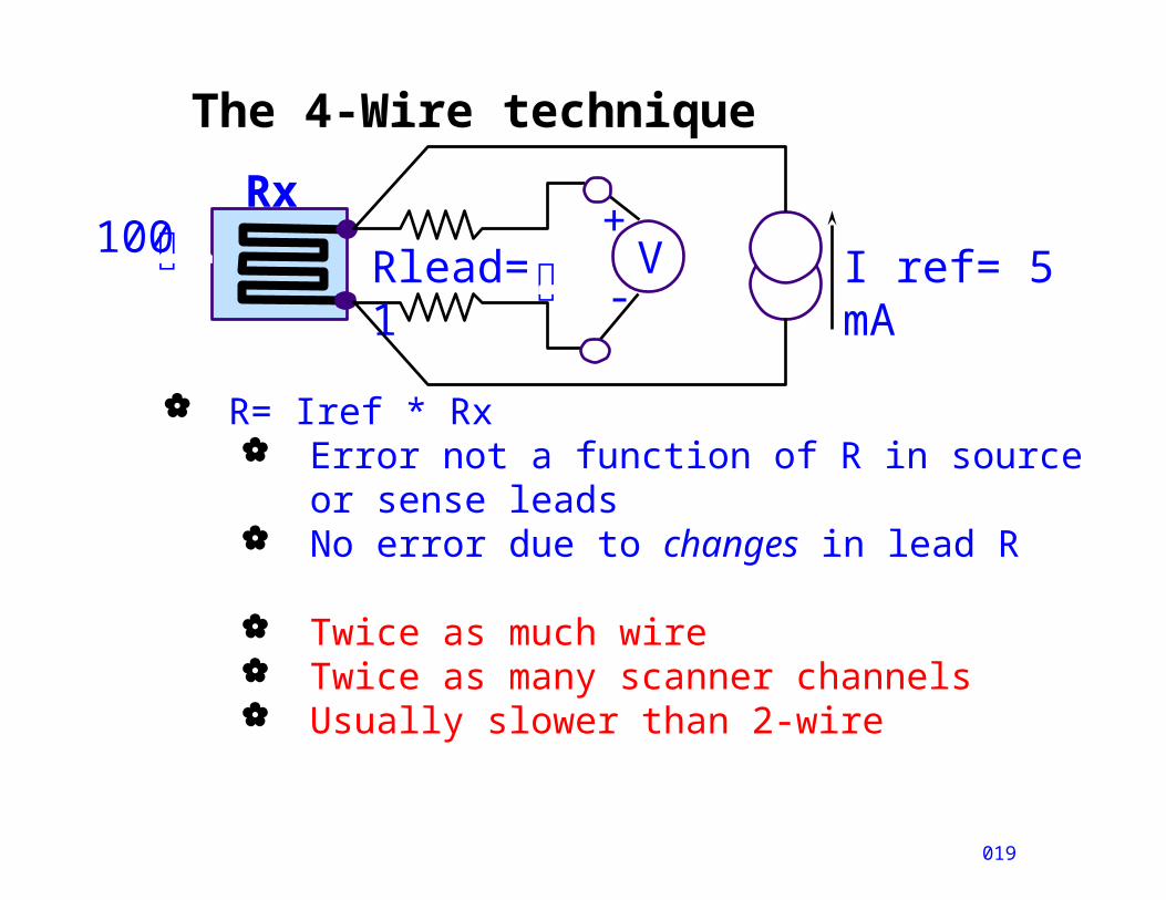
The 4-Wire technique
019
R= Iref * Rx Error not a function of R in source or sense
leads No error due to changes in lead R
Twice as much wire Twice as many scanner channels Usually slower than 2-wire
100 Rlead=
1V
-
+I ref= 5 mA
Rx
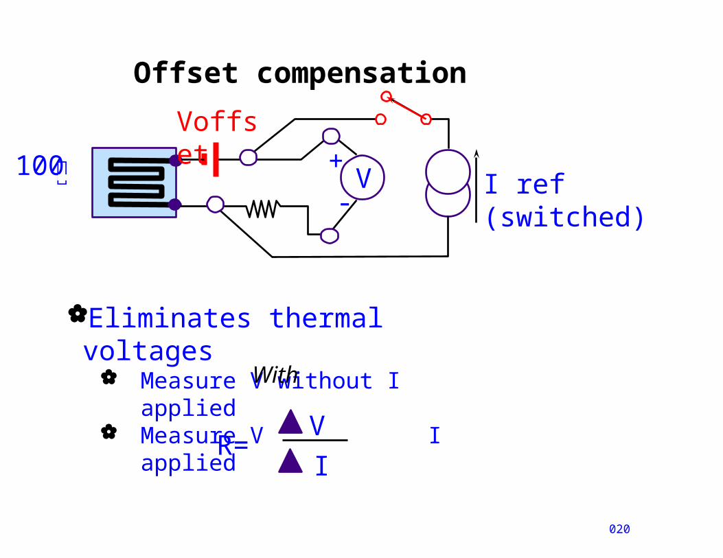
Offset compensation
020
Eliminates thermal voltages
Measure V without I applied Measure V I applied
R=
V
I
With
100
V-
+I ref (switched)
Voffset
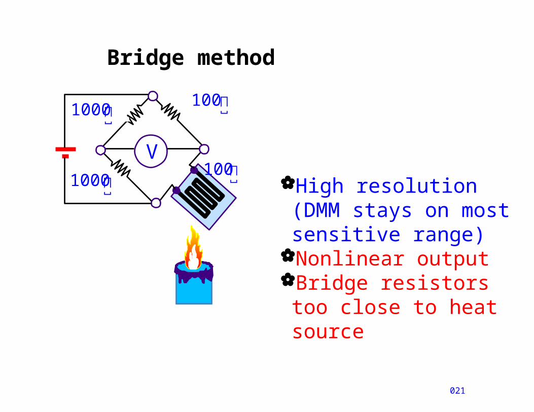
Bridge method
021
V
High resolution (DMM stays on most sensitive range)
Nonlinear outputBridge resistors too close to heat source
100
1001000
1000
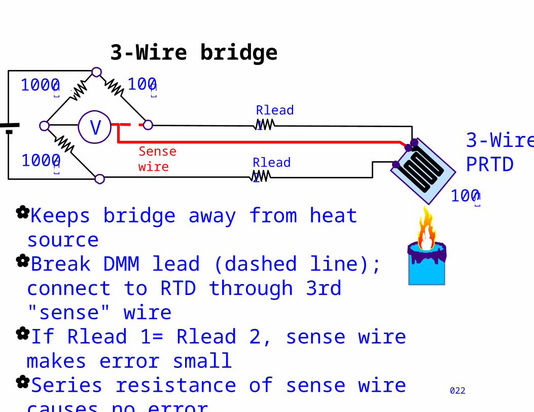
3-Wire bridge
022
V
1000
100
100
1000
Keeps bridge away from heat sourceBreak DMM lead (dashed line); connect to RTD through 3rd "sense" wire
If Rlead 1= Rlead 2, sense wire makes error small
Series resistance of sense wire causes no error
Rlead 1
Rlead 2
Sense wire
3-Wire PRTD
Agenda
A5
Background, historyMechanical sensorsElectrical sensors
Optical Pyrometer
RTD Thermistor,
IC Thermocouple
Summary & Examples
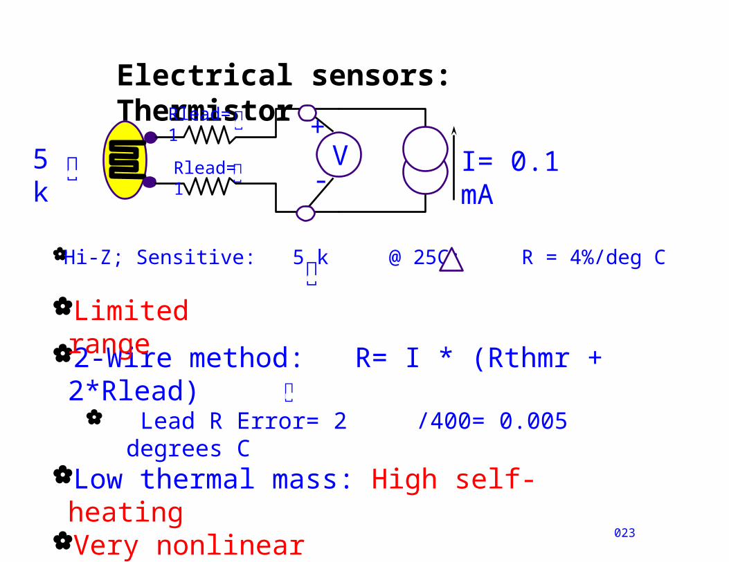
Electrical sensors: Thermistor
Hi-Z; Sensitive: 5 k @ 25C; R = 4%/deg C
023
5k
V-
+I= 0.1 mA
2-Wire method: R= I * (Rthmr + 2*Rlead)
Lead R Error= 2 /400= 0.005 degrees CLow thermal mass: High self-heatingVery nonlinear
Rlead=1
Rlead=1
Limited range
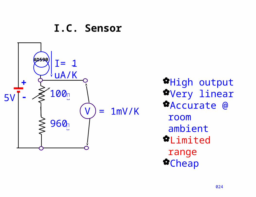
I.C. Sensor
+
-
024
V
I= 1 uA/K
5V 100
960
= 1mV/K
AD590
High outputVery linearAccurate @ room ambient
Limited range
Cheap
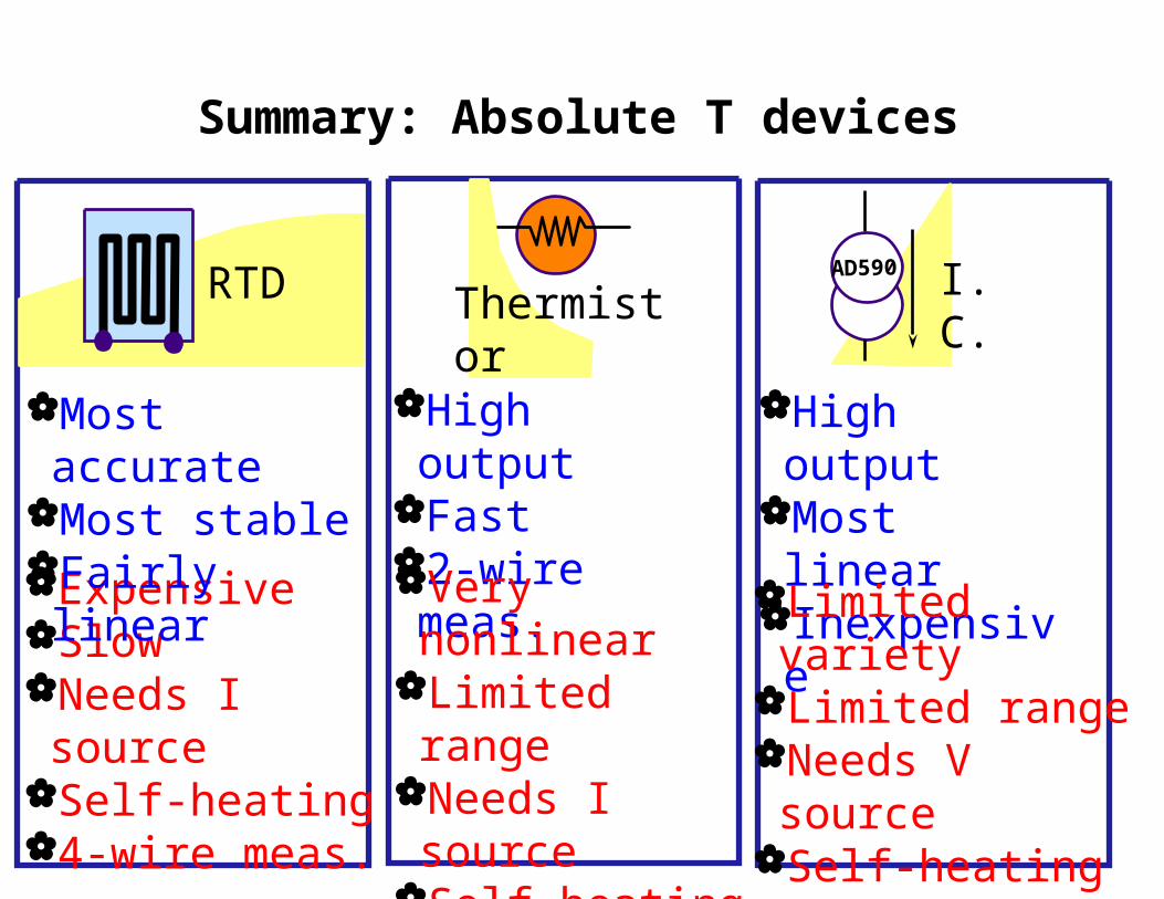
Summary: Absolute T devices
025
ExpensiveSlowNeeds I sourceSelf-heating4-wire meas.
RTD
Most accurate Most stableFairly linear
Thermistor
High outputFast2-wire meas.Very nonlinear
Limited rangeNeeds I sourceSelf-heatingFragile
AD590 I.C.
High outputMost linearInexpensive
Limited varietyLimited rangeNeeds V sourceSelf-heating
Agenda
A6
Background, historyMechanical sensorsElectrical sensors
Optical Pyrometer
RTD Thermistor, IC Thermocoup
leSummary & Examples
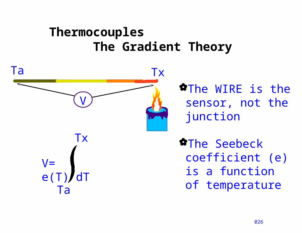
Thermocouples The Gradient Theory
026
TxTa
V
V= e(T) dT
Ta
Tx
The WIRE is the sensor, not the junction
The Seebeck coefficient (e) is a function of temperature

Making a thermocouple
027
Two wires make a thermocouple
Voltage output is nonzero if metals are not the sameV= e
dTTa
Tx
+ e dT
Ta
Tx
A B
Tx
Ta
V
TaA
B
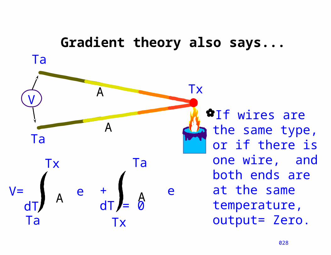
Gradient theory also says...
028
If wires are the same type, or if there is one wire, and both ends are at the same temperature, output= Zero.
V= e dT
Ta
Tx
+ e dT = 0
Ta
Tx
A A
Tx
Ta
V
TaA
A
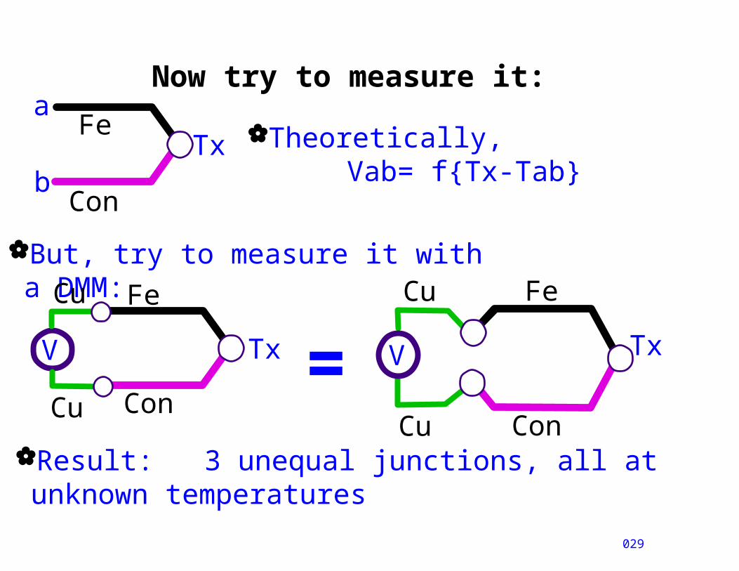
Now try to measure it:
Result: 3 unequal junctions, all at unknown temperatures
029
Theoretically, Vab= f{Tx-Tab}
But, try to measure it with a DMM:
Tx
Con
Fe
V
Cu
Cu=
Con
aTx
Fe
b
Cu Con
Fe
Tx
Cu
V
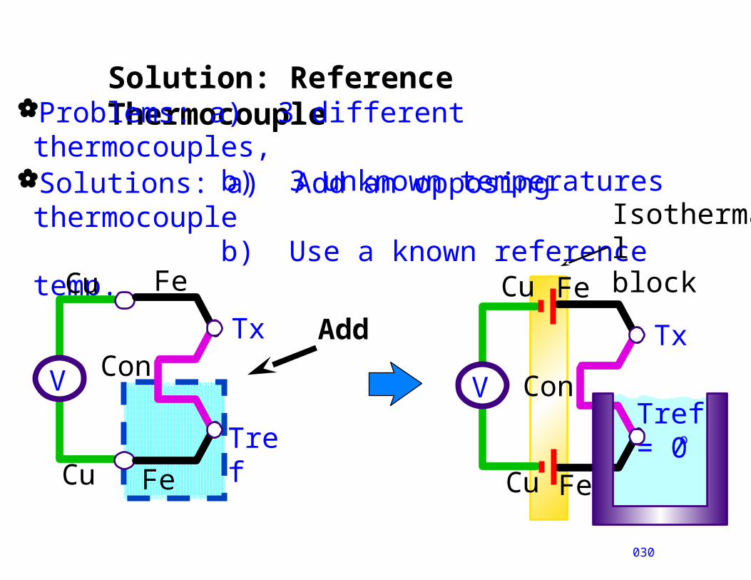
Solution: Reference Thermocouple
030
Problems: a) 3 different thermocouples, b) 3 unknown temperatures
Solutions: a) Add an opposing thermocouple
b) Use a known reference temp. Cu
V
Cu Fe
Tref= 0 C
Con
Fe
Tx
o
Isothermal block
Cu
V
Cu Fe
Tref
Con
Fe
Tx Add
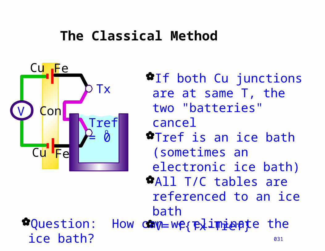
The Classical Method
031
Cu
V
Cu Fe
Tref= 0 C
Con
Fe
Tx
o
If both Cu junctions are at same T, the two "batteries" cancel
Tref is an ice bath (sometimes an electronic ice bath)
All T/C tables are referenced to an ice bath
V= f{Tx-Tref}
Question: How can we eliminate the ice bath?
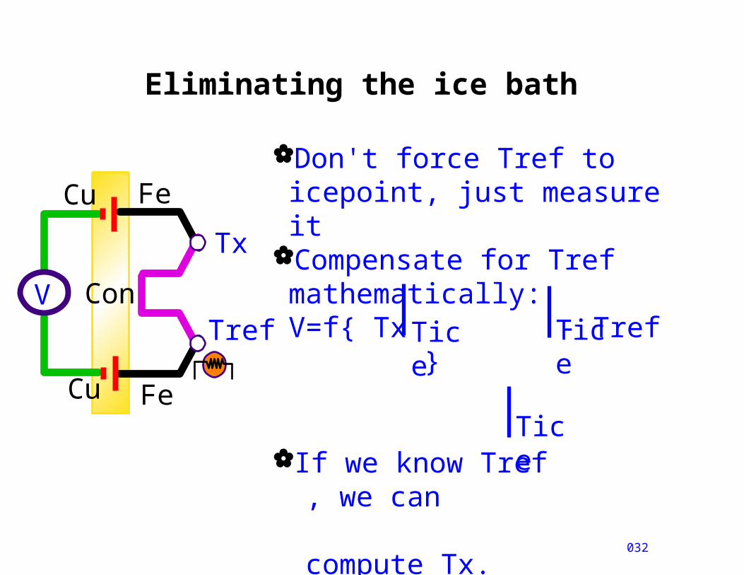
Eliminating the ice bath
032
Tref
Cu
V
Cu Fe
Con
Fe
Tx
Don't force Tref to icepoint, just measure it
Compensate for Tref mathematically:V=f{ Tx - Tref }
If we know Tref , we can
compute Tx.
TiceTice
Tice

Eliminating the second T/C
033
Extend the isothermal block
If isothermal, V1-V2=02
Cu
V
Cu Fe
Con
Fe
Tx
1
Cu
V
Cu
Con
Fe
Tx
2
1
Tref
Tref

The Algorithm for one T/C
Measure Tref: RTD, IC or thermistorTref ==> Vref @ O C for Type J(Fe-C)Know V, Know Vref: Compute VxSolve for using Vx
Tx
034
Cu
V
Cu
Con
Fe
Tx
Tref
0 Tref
VxVref
Tx
ComputeVx=V+Vref
V
o
o
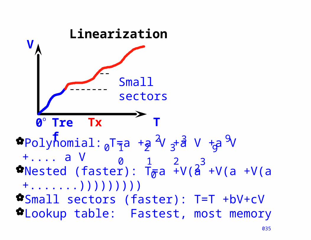
Linearization
035
Polynomial: T=a +a V +a V +a V +.... a VNested (faster): T=a +V(a +V(a +V(a +.......)))))))))
Small sectors (faster): T=T +bV+cV Lookup table: Fastest, most memory
2
1 2 32
0 1 2 33
99
00
0 Tref Txo
V
T
Small sectors

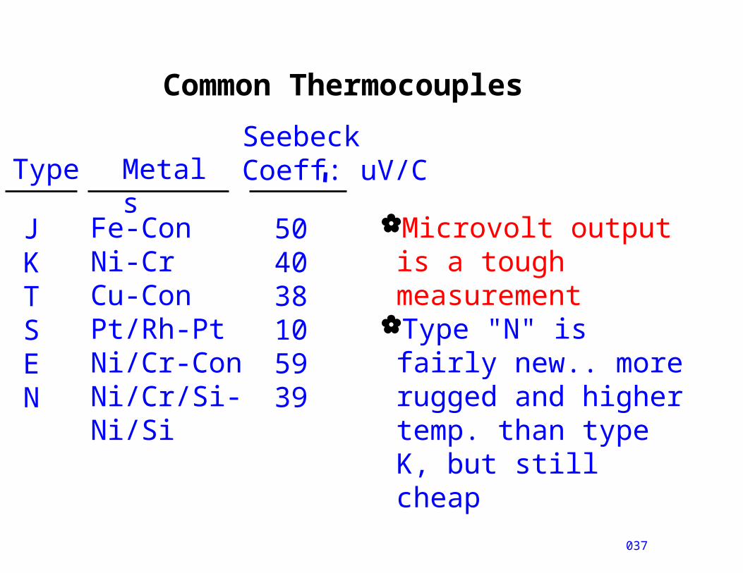
Common Thermocouples
036
0 500 1000 2000
mV
deg C
20
40
60
EE
R
NKJ
E
ST
Platinum T/CsBase Metal T/Cs
All have Seebeck coefficients in MICROvolts/deg.C
Common Thermocouples
037
SeebeckCoeff: uV/CType Metal
sJKTSEN
Fe-ConNi-CrCu-ConPt/Rh-PtNi/Cr-ConNi/Cr/Si-Ni/Si
504038105939
Microvolt output is a tough measurement
Type "N" is fairly new.. more rugged and higher temp. than type K, but still cheap
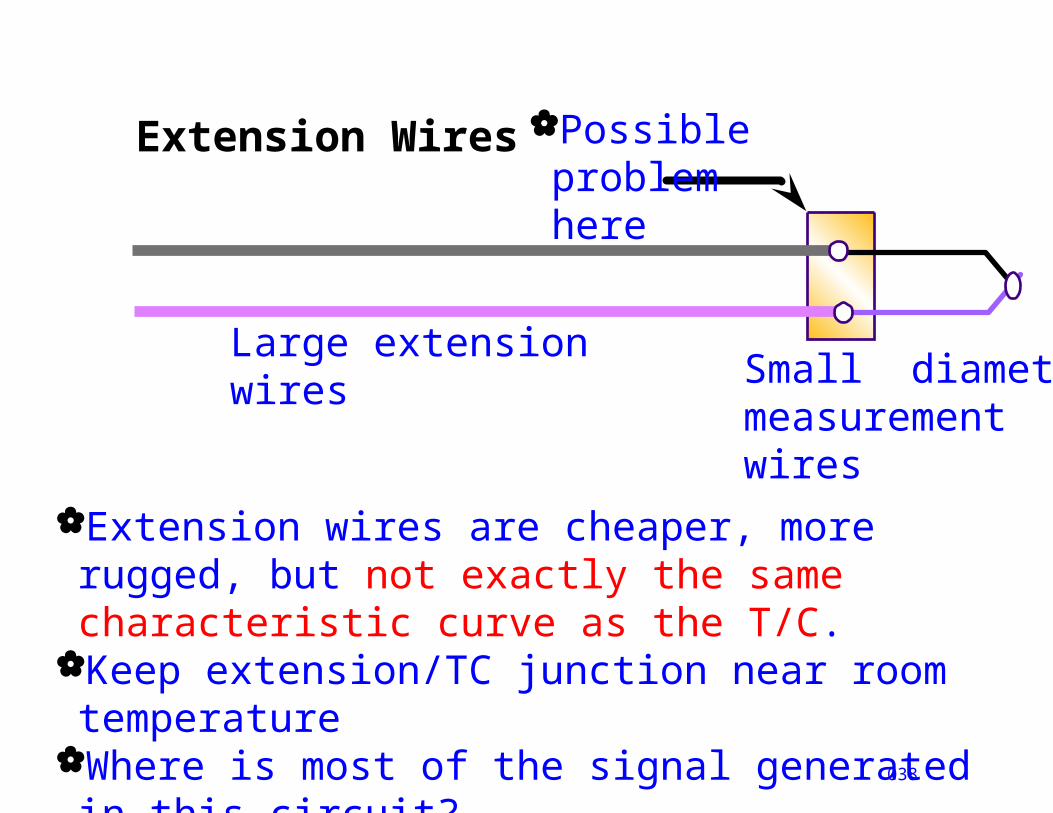
Extension Wires
038
Large extension wires Small diameter
measurementwires
Possible problemhere
Extension wires are cheaper, more rugged, but not exactly the same characteristic curve as the T/C.
Keep extension/TC junction near room temperature
Where is most of the signal generated in this circuit?
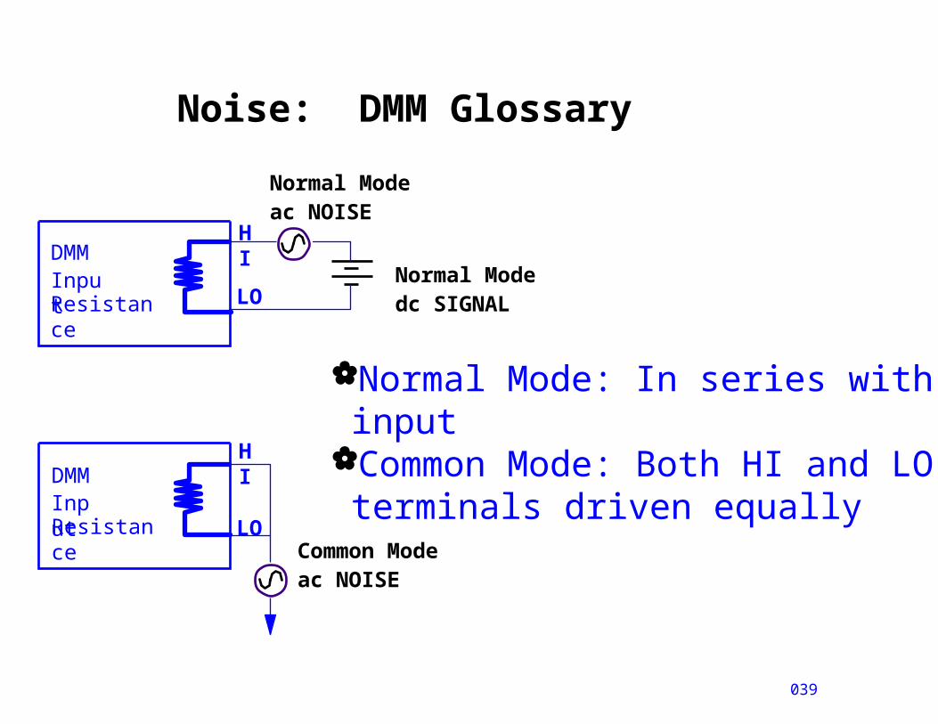
Noise: DMM Glossary
039
DMMInputResistance
Normal Modedc SIGNAL
Normal Modeac NOISE
DMMInputResistance Common Mode
ac NOISE
HI
HI
LO
LO
Normal Mode: In series with input
Common Mode: Both HI and LOterminals driven equally
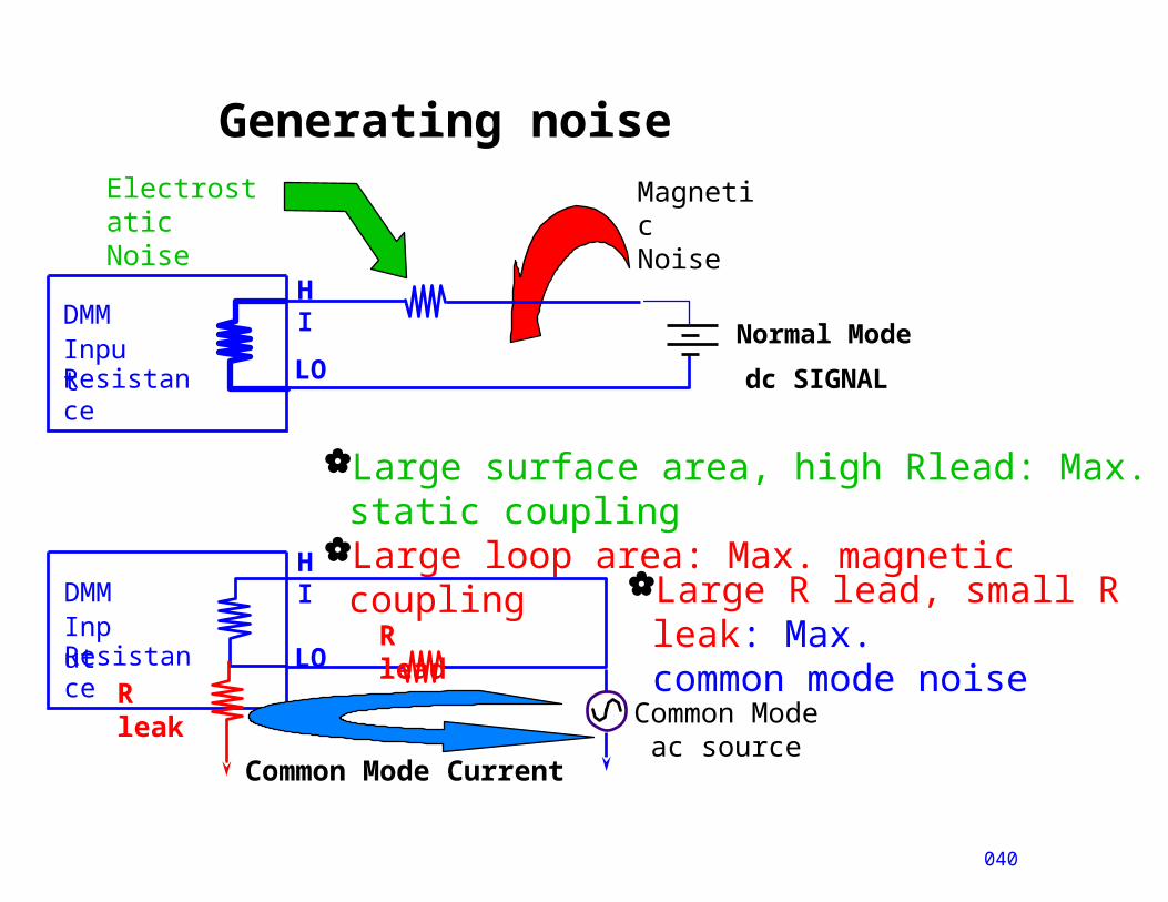
Generating noise
040
Normal Mode
Large surface area, high Rlead: Max. static coupling
Large loop area: Max. magnetic coupling
DMMInputResistance
dc SIGNAL
DMMInputResistance
HI
HI
LO
LO
ElectrostaticNoise
MagneticNoise
Common Mode ac source
R lead
R leak
Common Mode Current
Large R lead, small R leak: Max.common mode noise
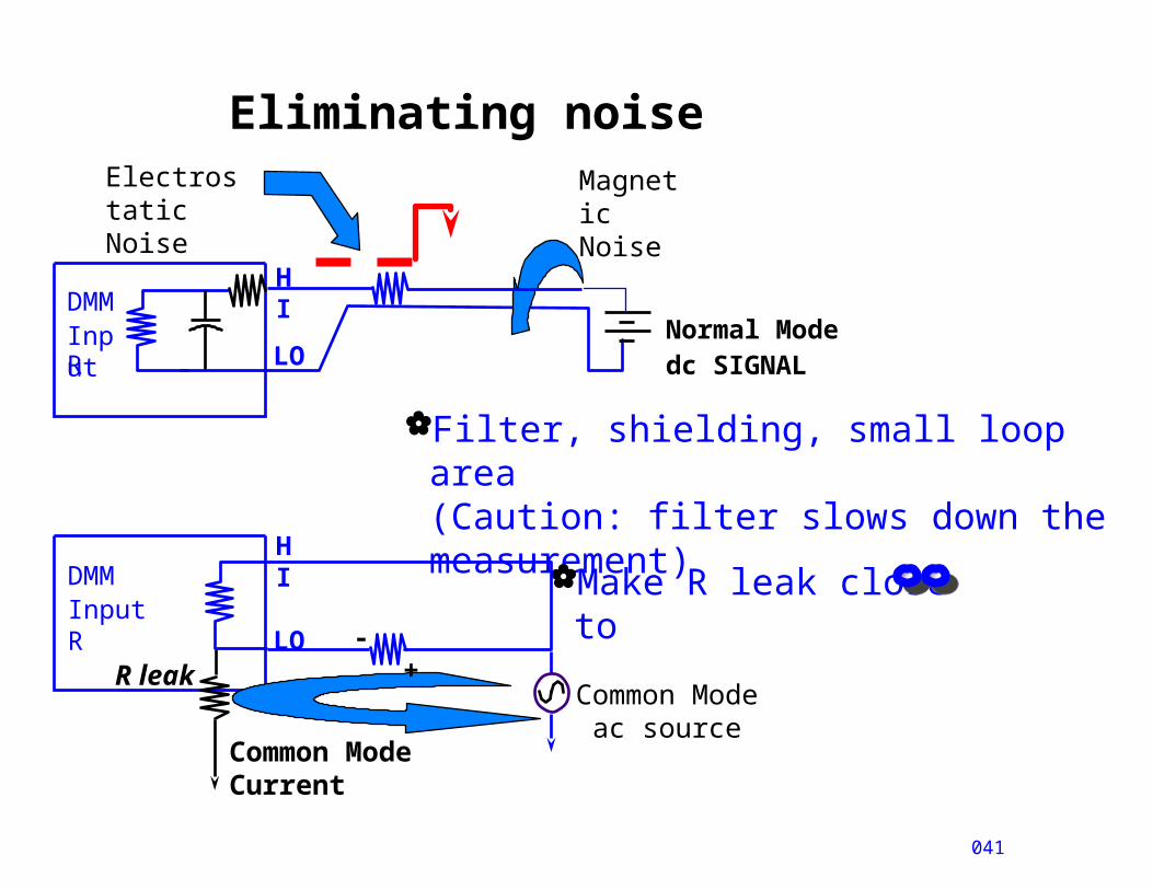
Eliminating noise
041
Normal Modedc SIGNAL
Filter, shielding, small loop area(Caution: filter slows down the measurement)
Make R leak close to
DMMInputR
DMMInput R
HI
HI
LO
LO
ElectrostaticNoise
MagneticNoise
Common Mode ac source
R leak
Common Mode Current
- +
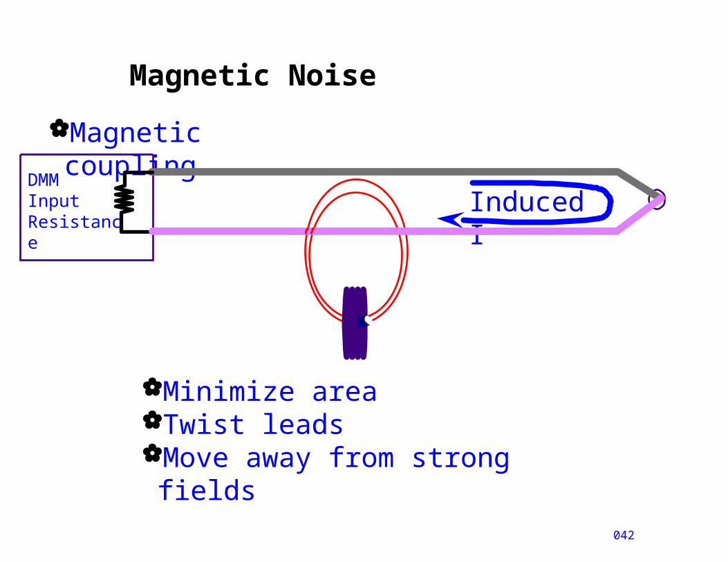
Magnetic Noise
042
Magnetic coupling
DMMInputResistance
Induced I
Minimize areaTwist leadsMove away from strong fields
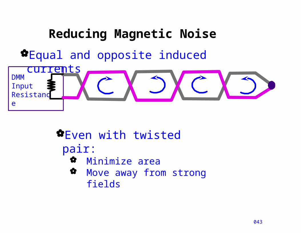
Reducing Magnetic Noise
043
Equal and opposite induced currents
DMMInputResistance
Even with twisted pair: Minimize area Move away from strong
fields
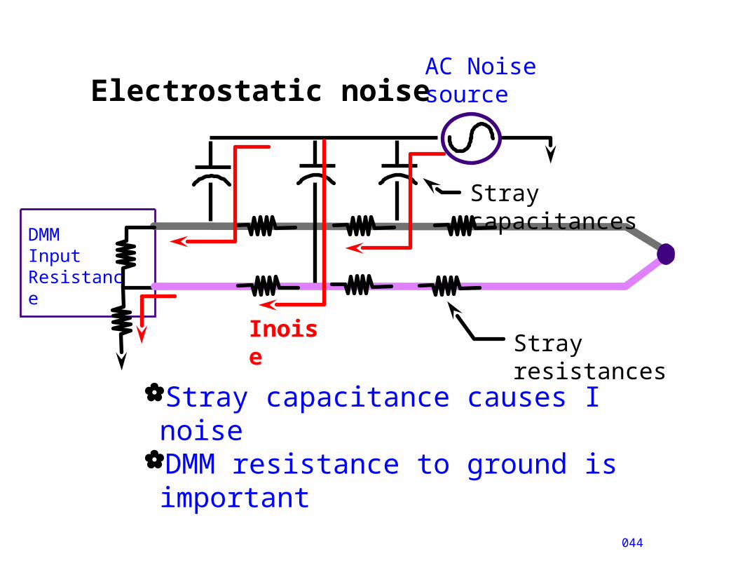
Electrostatic noise
044
DMMInputResistance
Stray capacitance causes I noiseDMM resistance to ground is important
Stray resistances
AC Noisesource
Stray capacitances
Inoise
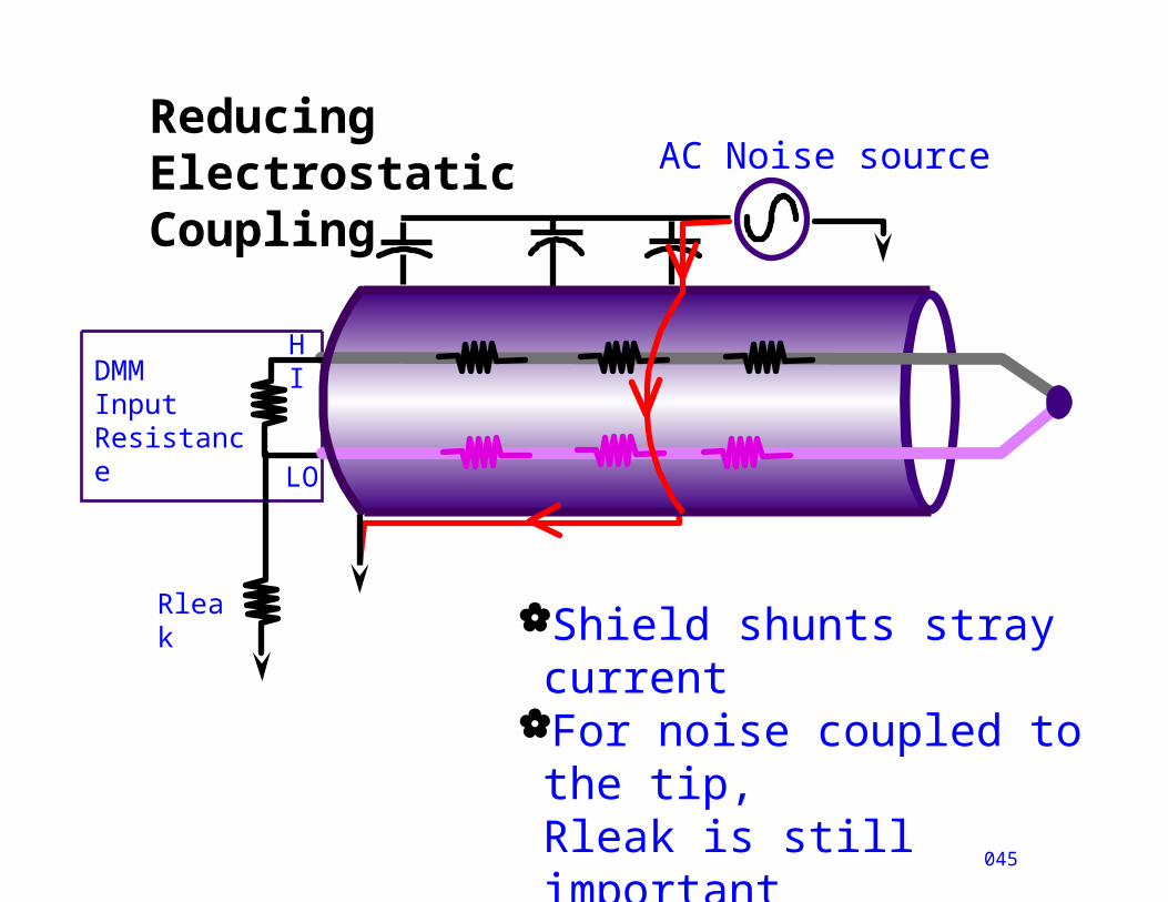
Reducing Electrostatic Coupling
045
DMMInputResistance
Shield shunts stray current
For noise coupled to the tip, Rleak is still important
AC Noise source
HI
LO
Rleak
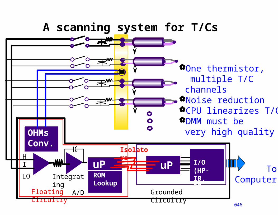
A scanning system for T/Cs
OHMsConv.
046
HI
LO
Floating Circuitry
Grounded Circuitry
Isolators
uP
uP
I/O(HP-IB,RS-232)
ToComputer
ROMLookup
Integrating A/D
One thermistor, multiple T/C channels
Noise reductionCPU linearizes T/CDMM must be
very high quality
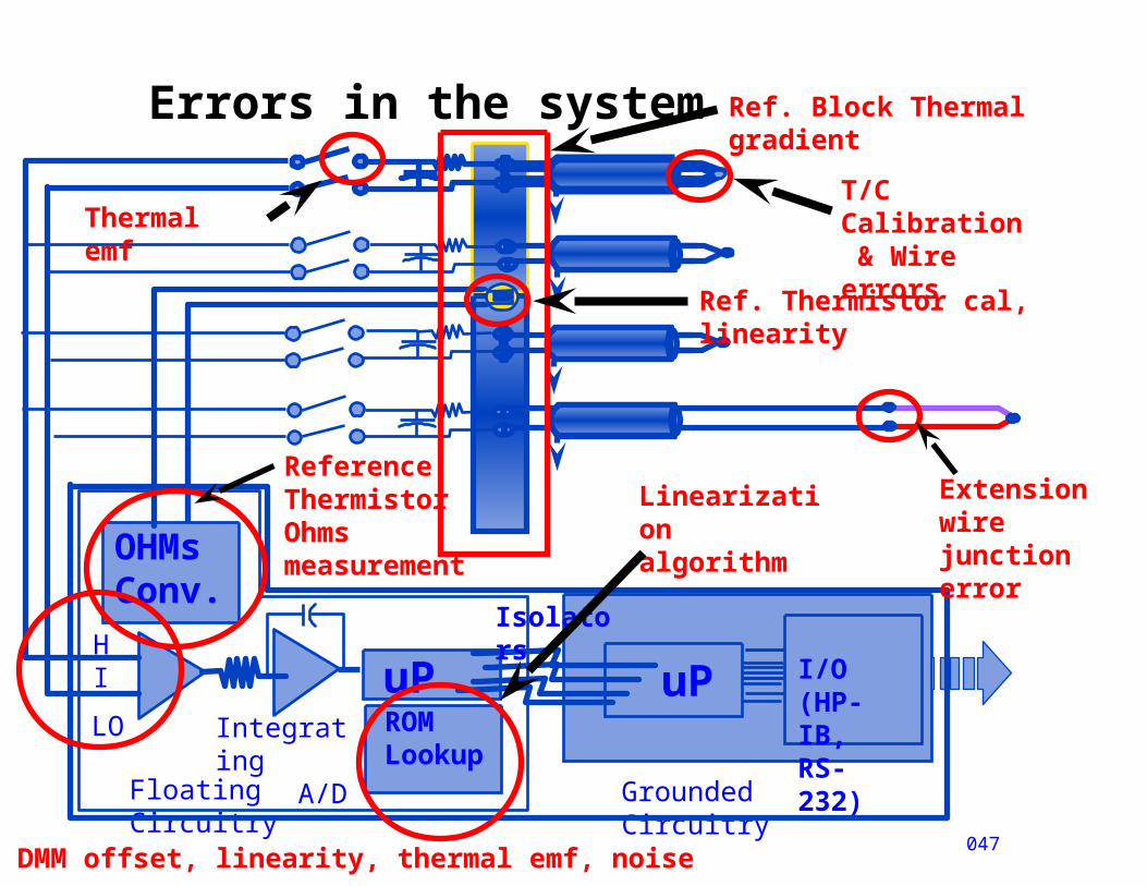
Errors in the system
OHMsConv.
047
HI
LO
Floating Circuitry
Grounded Circuitry
Isolators
uP
uP
I/O(HP-IB,RS-232)ROM
LookupIntegrating A/D
Thermal emf
Linearization algorithm
ReferenceThermistorOhmsmeasurement
Ref. Thermistor cal, linearity
T/C Calibration & Wire errors
Ref. Block Thermal gradient
DMM offset, linearity, thermal emf, noise
Extension wirejunction error

Physical errors
048
Shorts, shunt impedance
Galvanic actionDecalibration
Sensor accuracyThermal contactThermal shunting
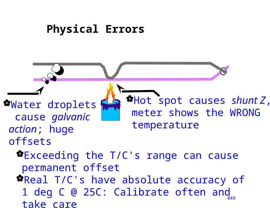
Physical Errors
049
Water droplets cause galvanic action; huge offsets
Hot spot causes shunt Z, meter shows the WRONG temperature
Exceeding the T/C's range can cause permanent offset
Real T/C's have absolute accuracy of 1 deg C @ 25C: Calibrate often and take care
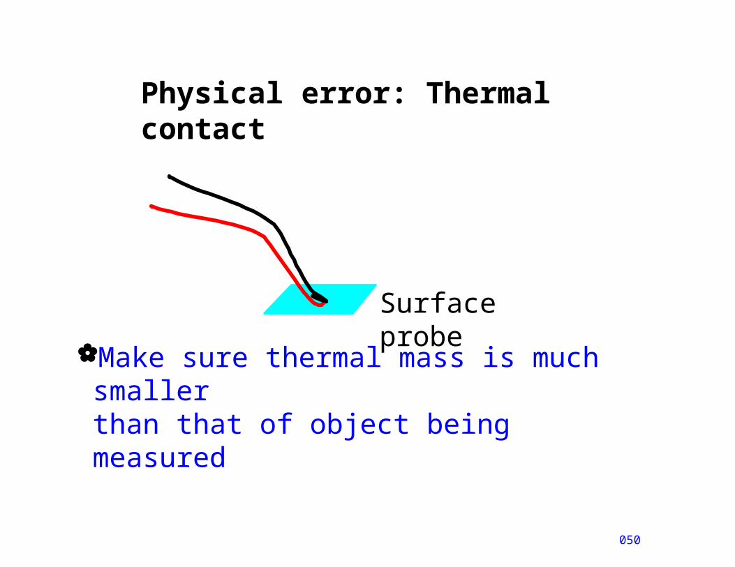
Physical error: Thermal contact
050
Surface probe
Make sure thermal mass is much smallerthan that of object being measured
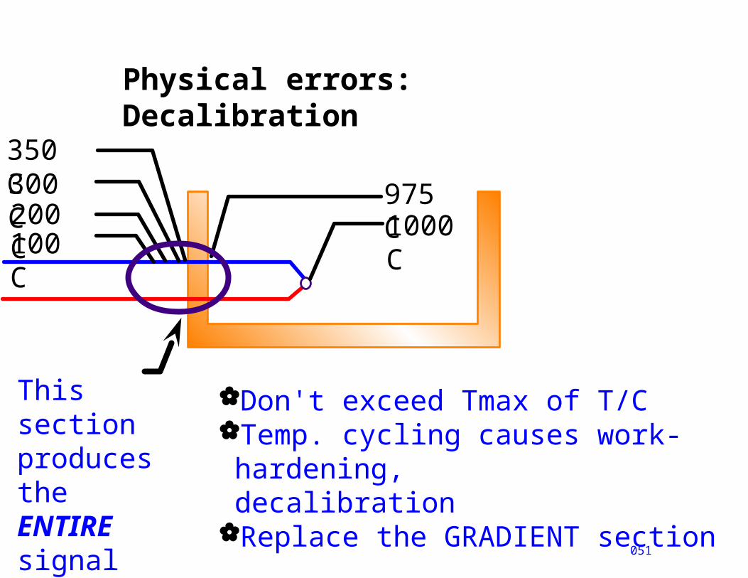
Physical errors: Decalibration
051
1000 C
200 C300 C350 C
975 C
100 C
This section produces theENTIRE signal
Don't exceed Tmax of T/CTemp. cycling causes work-hardening,decalibration
Replace the GRADIENT section
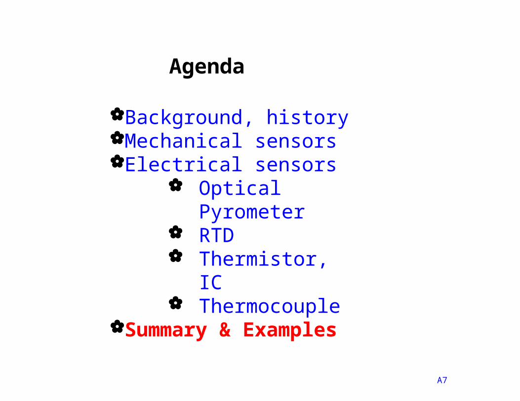
Agenda
A7
Background, historyMechanical sensorsElectrical sensors
Optical Pyrometer
RTD Thermistor, IC Thermocouple
Summary & Examples
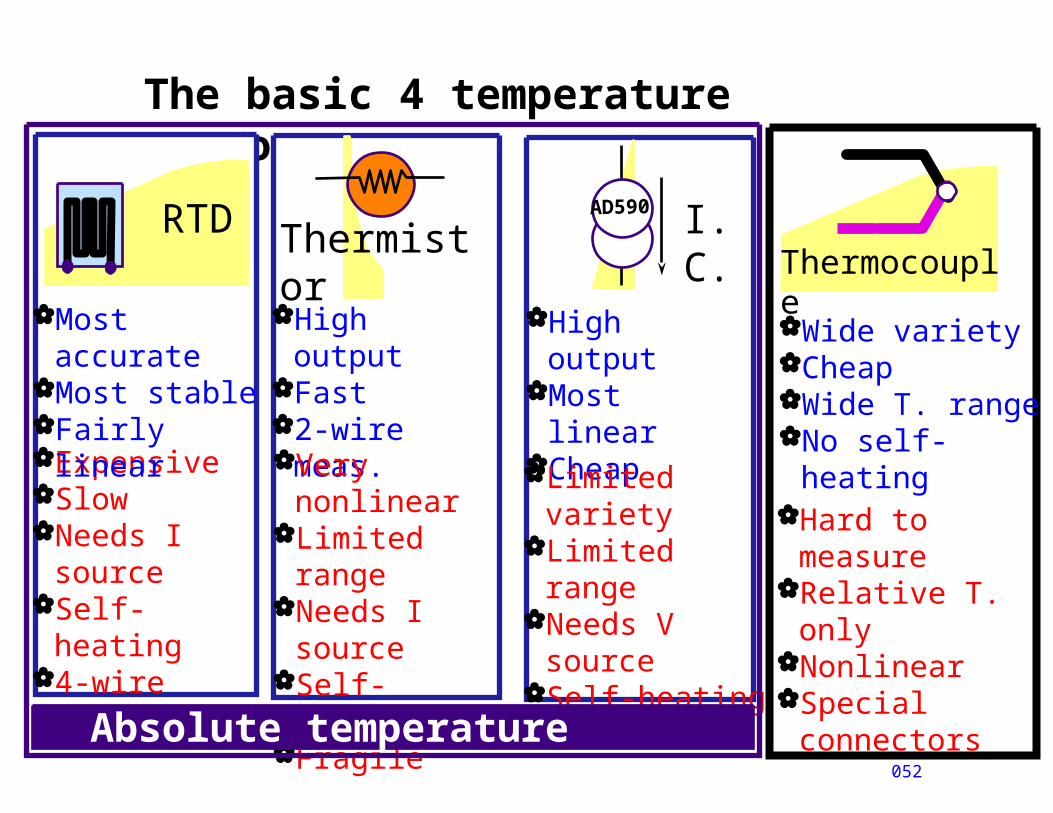
The basic 4 temperature sensors
052
ThermocoupleWide varietyCheapWide T. rangeNo self-heating
Hard to measure
Relative T. only
NonlinearSpecial
connectors
AD590
ExpensiveSlowNeeds I
sourceSelf-heating4-wire meas.
RTD
Most accurate
Most stableFairly linear
ThermistorHigh outputFast2-wire
meas.Very
nonlinearLimited rangeNeeds I
sourceSelf-heatingFragile
I.C.
High output
Most linearCheapLimited
varietyLimited rangeNeeds V
sourceSelf-heating
Absolute temperature sensors
Summary
053
Innovation by itself is not enough...you must develop standards
Temperature is a very difficult, mostly empirical measurement
Careful attention to detail is required
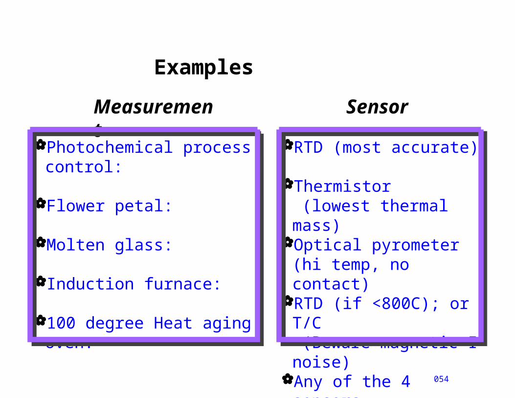
Examples
054
Photochemical process control:
Flower petal:
Molten glass:
Induction furnace:
100 degree Heat aging oven:
Measurement
Sensor
RTD (most accurate)
Thermistor (lowest thermal mass)
Optical pyrometer (hi temp, no contact)
RTD (if <800C); or T/C (Beware magnetic I noise)
Any of the 4 sensors