practical method of conducting the indirect tensile test · tensile test and standard texas highway...
TRANSCRIPT

PRACTICAL METHOD OF CONDUCTING THE INDIRECT TENSILE TEST
by
James N. Anagnos Thomas W. Kennedy
Research Report Number 98-10
Evaluation of Tensile Properties of Subbases for Use in New Rigid Pavement Design
Research Project 3-8-66-98
conducted for
The Texas Highway Department
in cooperation with the LT. S. Department of Transportation
Federal Highway Administration
by the
CENTER FOR HIGHWAY RESEARCH
THE UNIVERSITY OF TEXAS AT AUSTIN
August 1972

The contents of this report reflect the views of the authors, who are responsible for the facts and the accuracy of the data presented herein. The contents do not necessarily reflect the official views or policies of the Federal Highway Administration. This report does not constitute a standard, specification, or regulation.
ii

PREFACE
This is the tenth in a series of reports dealing with the findings of a
research project concerned with the evaluation of the tensile properties of
stabilized subbase materials. The equipment and test procedures involved in
conducting the indirect tensile test are described in detail. In addition a
method of analysis of the test results to determine tensile strength, Poisson's
ratio, modulus of elasticity, and total tensile strain at failure is also
described.
Special appreciation is due to Messrs. James L. Brown, Larry J. Buttler,
and Dr. Robert E. Long of the Texas Highway Department, who provided technical
liaison for the project.
Future reports will be concerned with
(1) tensile properties for use in the design of cement-treated materials,
(2) tensile behavior of stabilized materials under repetitive loads, and
(3) a comprehensive design for stabilized bases.
August 1972
iii
James N. Anagnos
Thomas W. Kennedy

LIST OF REPORTS
Report No. 98-1, "An Indirect Tensile Test for Stabilized Materials," by W. Ronald Hudson and Thomas W. Kennedy, summarizes current knowledge of the indirect tensile test, reports findings of limited evaluation of the test, and describes the equipment and testing techniques developed.
Report No. 98-2, "An Evaluation of Factors Affecting the Tensile Properties of Asphalt-Treated Materials," by William O. Hadley, W. Ronald Hudson, and Thomas W. Kennedy, discusses factors important in determining the tensile strength of asphalt-treated materials and reports findings of an evaluation of eight of these factors.
Report No. 98-3, '~valuation of Factors Affecting the Tensile Properties of Cement-Treated Materials," by Humberto J. Pendola, Thomas W. Kennedy, and W. Ronald Hudson, presents factors important in determining the strength of cement-treated materials and reports findings of an evaluation by indirect tensile test of nine factors thought to affect the tensile properties of cement-treated materials.
Report No. 98-4, '~valuation of Factors Affecting the Tensile Properties of Lime-Treated Materials," by S. Paul Miller, Thomas W. Kennedy, and W. Ronald Hudson, presents factors important in determining the strength of cementtreated materials and reports findings of an evaluation by indirect tensile test of eight factors thought to affect the tensile properties of limetreated materials.
Report No. 98-5, '~valuation and Prediction of the Tensile Properties of LimeTreated Materials," by Walter S. Tulloch, II, W. Ronald Hudson, and Thomas W. Kennedy, presents a detailed investigation by indirect tensile test of five factors thought to affect the tensile properties of lime-treated materials and reports findings of an investigation of the correlation between the indirect tensile test and standard Texas Highway Department tests for lime-treated materials.
Report No. 98-6, 'torrelation of Tensile Properties with Stability and Cohesiorncter Values for i\sphalt-Treated Materials," by William O. Hadley, W. Ronald lludson, and Thomas w. Kennedy, presents a detailed correlation of indirect t('l1s:ile lest parameters, i.e., strength, modulus of elasticity, Poisson's ratio, and failure strain, with stability and cohesiometer values for asphulttreated materials.
Report No. 98-7, '~Method of Estimating Tensile Properties of Materials Tested in Indirect Tension," by William O. Hadley, W. Ronald Hudson, and Thomas W. Kennedy, presents the development of equations for estimating material properties such as modulus of elasticity, Poisson's ratio, and tensile strain based upon the theory of the indirect tensile test and reports verification of the equations for aluminum.
iv

v
Report No. 98-8, "Evaluation and Prediction of Tensile Properties of CementTreated Materials," by James N. Anagnos, Thomas W. Kennedy, and W. Ronald Hudson, investigates, by indirect tensile test, six factors affecting the tensile properties of cement-treated materials, and reports the findings of an investigation of the correlation between indirect tensile strength and standard Texas Highway Department tests for cement-treated materials.
Report No. 98-9, "Evaluation and Prediction of the Tensile Properties of Asphalt-Treated Materials," by William O. Hadley, W. Ronald Hudson, and Thomas W. Kennedy, presents a detailed investigation by indirect tensile test of seven factors thought to affect the tensile properties of asphalt-treated materials and reports findings which indicate the important factors affecting each of the tensile properties and regression equations for estimation of the tensile properties.
Report No. 98-10, "Practical Method of Conducting the Indirect Tensile Test," by James N. Anagnos and Thomas W. Kennedy, describes equipment and test procedures involved in conducting the indirect tensile test along with a method of analyzing the test results.

ABSTRACT
This report describes a practical method of conducting the indirect ten
sile test and a method of analyzing the test results to determine the tensile
properties of all types of stabilized materials except cohesionless materials.
The test methods are reported in two parts. The first describes the rela
tively simple equipment and test procedures required to obtain tensile strength.
The second part describes equipment, test procedures, and a method of analysis
to determine Poisson's ratio, modulus of elasticity, and tensile strains.
KEY WORDS: test equipment, test procedures, method of analysis, tensile
strength, Poisson's ratio, modulus of elasticity, tensile strains.
vi

SUMMARY
The purpose of this report is to describe in detail a practical method
of conducting the indirect tensile test to determine the tensile properties
of stabilized materials. A pair of half-inch-wide curved face loading strips
and loading equipment capable of applying a compressive load at a controlled
deformation rate, preferably 2 inches per minute, must be used to determine
tensile strength. The large motorized gyratory press in use by the Texas
Highway Department can provide this loading rate and can be easily modified
to accept the loading strips. From the dimensions of the test specimen and
failure load, the tensile strength can be calculated.
The determination of Poisson's ratio, modulus of elasticity, and tensile
strains requires the measurement of vertical and horizontal deformations of
the specimen at various applied loads. Simple mathematical equations have
been developed to calculate these tensile properties.
vii

IMPLEMENTATION STATEMENT
The information contained in this report describes the indirect tensile
test, the equipment and procedures required to conduct the test, and the
method of calculating the tensile properties of the material tested. Emphasis
has been placed on utilizing equipment readily available to the district labora
tories of the Texas Highway Department.
The test can be used to evaluate all stabilized materials, and it is
hoped that it can be used to evaluate all pavement materials except cohesion
less materials. Thus, it will be possible to compare the behavioral charac
teristics of these materials on the same basis using the same test. The ten
sile properties obtained from this test are expressed in terms of standard
engineering units, which are more meaningful than empirical numbers and which
can be used in theoretical design procedures requiring the elastic constants
n[ the materials involved. In addition, since the test is very simple to con
duct and uses cylindrical specimens which are easily prepared, it can be used
to control quality of construction materials.
viii

TABLE OF CONTENTS
PREFACE •
LIST OF REPORTS •
ABSTRACT
SUMMARY.
IMPLEMENTATION STATEMENT
INTRODUCTION
INDIRECT TENSILE TEST •
DETERMINATION OF INDIRECT TENSILE STRENGTH
Equipment Test Procedure Calculation of Indirect Tensile Strength •
DETERMINATION OF POISSON'S RATIO, MODULUS OF ELASTICITY, AND TENSILE STRAINS AT FAILURE
Equipment Test Procedure • Calculation of Tensile Properties
REFERENCES
APPENDIX 1. GENERAL - SPECIAL EQUIPMENT REQUIRED TO OBTAIN TENSILE STRENGTH •
I\PPEf'..'l)JX 2. TEXAS HIGHWAY DEPART:tvlENT - SPECIAL EQUIPt-lENT REQUll{ED TO OBTAIN TENS lLE STRENGTH
ix
iii
iv
vi
vii
viii
1
2
5 9 9
11 14 14
21
23
26

APPENDIX 3.
APPENDIX 4.
THE AUTHORS
SPECIAL EQUIPMENT REQUIRED TO DETERMINE POISSON'S RATIO, MODULUS OF ELASTICITY, AND TENSILE STRAINS AT FAILURE HORIZONTAL DEFORNATION DEVICE CALIBRATION •••••••••
. . . . . . . . . . . . . . . . . . . . . . . . . . . . . .
31 41
43
x

INTRODUCTION
A need exists for a simple test method which can be used to evaluate the
tensile properties of all types of pavement materials and to obtain informa
tion which can be used for pavement design. In addition to failing from
cracking of the surface layers, rigid pavements may fail due to loss of sup
port as the result of subbase cracking, and flexible pavements may also fail
due to the formation of tensile cracks in the subbase and base layers with
subsequent propogation of the crack upward through the surface layer.
In recognition of the need for information on the tensile characteristics
of stabilized subbase materials, the Texas Highway Department and the Federal
Highway Administration sponsored Project 3-8-66-98, ''Evaluation of Tensile
Properties of Subbases for Use in Rigid Pavement Design," which was conducted
by the Center for Highway Research at The University of Texas at Austin. As
a part of this project, the various tests which were currently available and
which could be used to obtain information on the tensile characteristics of
highway materials were evaluated (Ref 3). As a result, the indirect tensile
test or splitting tensile test was adopted and further developed to provide a
test method which could be used to obtain estimates of tensile strength,
Poisson's ratio, modulus of elasticity, and tensile strains for all types of
stabilized materials (Ref 1). In addition, it is felt that the test can be
used to evaluate other pavement materials except cohesion1ess materials, such
as sand, gravel, and crushed stone.
The purpose of this report is to provide a detailed description of the
test, test procedures, equipment, and methods of calculating tensile strength,
Poisson's ratio, modulus of elasticity, and tensile strains. The portion of
the report concerned with procedures, equipment, and methods of calculating
the various properties has been divided into two sections, since determination
of tensile strength is relatively simple, requiring only a method of applying
and measuring the total compressive load applied to the specimen, whereas the
determination of Poisson's ratio, modulus of elasticity, and tensile strain is
more difficult, requiring accurate measurements of specimen deformations.
1

INDIRECT TENSILE TEST
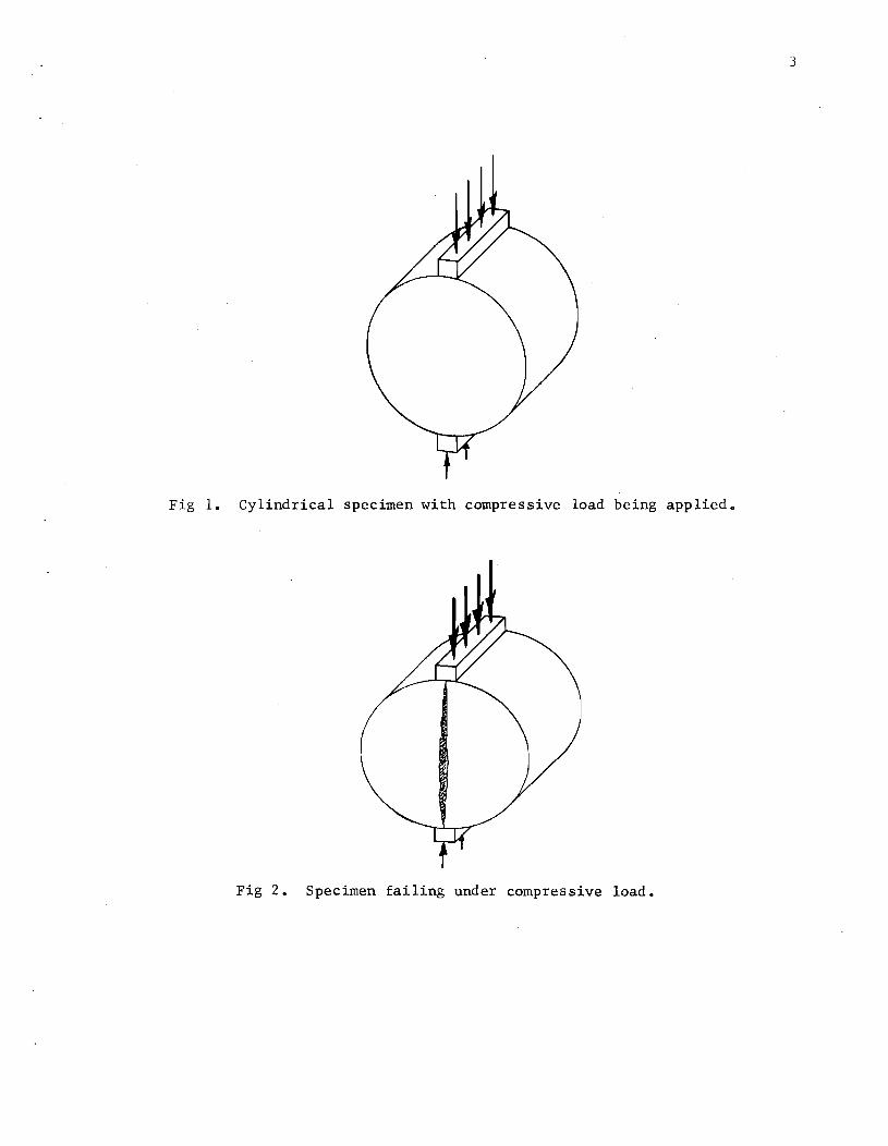
The indirect tensile test involves loading a cylindrical specimen with
compressive loads which act parallel to and along the vertical diametrical
plane, as shown in Fig 1. To distribute the load and maintain a constant
loading area, the compressive load is applied through a ha1f-inch-wide stain
less steel loading strip which is curved at the interface with the specimen
and has a radius equal to that of the specimen.
This loading configuration develops a relatively uniform tensile stress
perpendicular to the direction of the applied load and along the vertical
diametrical plane, which ultimately causes the specimen to fail by splitting
or rupturing along the vertical diameter (Fig 2). The tensile stress in the
center of the specimen can be calculated using the following equation:
where
= 2P (sin 20' _ 2.) ~ah D
(1)
aT = indirect tensile stress;
P = total vertical load applied to specimen, in pounds;
a = width of loading strip, in inches;
h = height of specimen at beginning of test, in inches;
D = diameter of specimen, in inches; and
20' = angle at the origin subtended by the width of loading strip (Fig 3).
When P is maximum, aT equals the indirect tensile strength ST.
2
In addition, based upon developments by Project 3-8-66-98 at the Center
for Highway Research, it is possible to estimate Poisson's ratio, modulus of
elasticity, and total tensile strain at failure. The theoretical relationships
required for calculating these parameters are contained in Center for Highway
]{esearch Report No. 98-9 (Ref 1). These relationships are rather complex and
require integration of various mathematical functions. However, by assuming
a specimen diameter the required integrations can be conducted and the rela
tionships can be simplified. The simplified relationships for calculating
3
Fig 1. Cylindrical specimen with compressive load being applied.
Fig 2. Specimen failing under compressive load.

p:: Applied Load a = Width of Loading Strip h = Height of Specimen R= Radius of Specimen
p
p
Stainless Steel Load ing Strip
2a= Angle at Origin Subtended by Width of Loading Strip
Fig 3. Indirect tensile test.
4

Poisson's ratio, modulus of elasticity, and failure strains for 4-inch and
6-inch diameter specimens with a half-inch-wide curved loading strip are sum
marized in Table 1.
5
It is recommended that the test be conducted at a controlled deformation
rate of 2 inches per minute at 75 0 F utilizing half-inch-wide curved face
loading strips. Other loading rates and testing temperatures can be utilized
for studies of special interest, and in the case of relatively stiff materials
it may be desirable to reduce the loading rate.
The remainder of this report describes the procedures and equipment re
quired to conduct the test and to obtain estimates of tensile strength, Poisson's
ratio, modulus of elasticity, and tensile strains.
DETERMINATION OF INDIRECT TENSILE STRENGTH
EQUIPMENT
The basic testing apparatus includes loading equipment capable of apply
ing compressive loads at a controlled deformation rate, preferably 2 inches
per minute, a means of measuring the applied load, and half-inch-wide curved
face loading strips, which are used to apply and distribute the load uniformly
along the entire length of the specimen.
General Use
Any loading equipment which is capable of applying compressive loads at a
prescribed loading rate and can provide an accurate measure of the maximum
loau can be used, providing that the load capacity of the equipment is suffi
cient to fail the specimen. In addition, since it is necessary to apply the
load to the specimen through steel loading strips which must remain essentially
parallel, it is recommended that a guided loading head with loading strips
attached to the upper and lower parallel platens be used. Such a device, \\7hich
has been used at the Center for Highway Research, can be obtained by modifying
a commercially available die set such as shown in Fig 5. The specifications
and required modifications for this die set and the loading strips are pre
sented in Appendix 1.

6
TABLE 1. EQUATIONS FOR CALCULATION OF TENSILE PROPERTIES
Diameter of Specimen
Tensile Property 4-Inch 6-Inch
Tensile strength ST' psi
0.156 :Fail 0.105 :Fail
Poisson's ratio v 0.0673DR - 0.8954 -0.2494DR - 0.0156
0.04524DR - 0.6804 -0. 16648DR - 0.00694
Modulus of SH ,- """1
h LO.997 6v + 0.2692 J SH I """1
h LO.9990v + 0.2712 J elasticity E, psi
Total tensile strain at fai lure &T
X [0.1185v + 0.038961 TF 0.2494v + 0.0673J [
O.0793V + 0.0263J xTF 0.1665v + 0.0452
DR
S 11
*
total load at failure (maximum load point), in pounds;
height of specimen, in inches;
P or load at first break max
total horizontal deformation at failure (deformation at the maximum load or at first break point), in inches (Fig 4);
deformation ratio (the slope of line of best fit* between
vertical deformation YT and the corresponding horizontal deforma-
tion X'l' up to failure load P ) . Fail '
hori/:onlal t3ngent modulus (the slope of the line of best fit*
octWC'l'll l(lad P and tal a 1 11Orb:on ta 1 deforma tion
to failure load PFai1
).
X T
Cor loads tIp
It is recommended that the line of best fit be determined by the method of least squares.

2000
\First Break Point
(/) 1500 !=fail //\ ..c ______________________ -T.-~---'---o---.. "0
° .3 Q) >
.~ 1000 .... e. E o u "0
Q.)
§: 500 <l
o
Least Squares Line of Best Fit, For Loads up to Pfoil
/ /
/
/ /
/
S =f.Ej H \'l.TI
.001 .002
==, ~I -I °1 a l
:;::;\ °1 §I .21 ~I -I 9, al .~ I 01 II -I ~I F~I
u..1 :>fl
.003
• - Data Points Used to Obtain Least Squares Line of Best Fit
.004 .005
Total Horizontal Deformation t inches
Fig 4. Generalized characterization of load-horizontal deformation data.
7

Fig 5. Al l stee l pr c~s~on ic ~ et with luadlno ·trips and specimen in lace.
Fig 6 . No toriz eel gyl.a t r) pres s •
8

Texas Highway Department Use
Serious consideration should be given to using the motorized gyratory
press (Fig 6) for loading specimens since this press is available in most of
the district laboratories and in the Materials and Test Division of the Texas
Highway Department (Ref .2) and would require only minor modifications (Ap
pendix 2). The press is capable of applying compressive loads up to 25,000
pounds at controlled deformation rates ranging from 0.05 to 10 inches per
minute. If the gyratory press is used, probably the guided loading head 'I,
9
should not be used ; rather a different set of loading strips should be attached
directly to the platens of the gyratory press, as shown in Fig 7. Machine
drawings of the loading strips for use with the gyratory press are shown in
Appendix 2. In addition, a list of equipment needed to perform the test and
a description of the modifications of the press are contained in Appendix 2.
TEST PROCEDURE
(1) Determine the height and diameter of the test specimen.
(2) Carefully center the test specimen on the lower loading strip.
(3) Slowly bring the head down until light contact is made with the test specimen.
(4) Apply the load at a controlled deformation rate of 2 inches per minute and determine the maximum pressure at failure of the specimen.
CALCULATION OF INDIRECT TENSILE STRENGTH
Tensile strength for nominal 4-inch and 6-inch-diameter specimens can be
calculated from the following equations (Table 1):
"
4-inch-specimens
= PFail
0.156 h
Tile guided lOdding head can be used (Fig 7), but space limitations restrict tile specimen size to diameters and lengths of 6 inches or less.

ria 1 . ,.,..,.10001 11'0< ., ,La_ ."" """'.
..
" ... wL'" "_,

where
6-inch-diameter specimens
=
h
PFai1 0.105 h
= indirect tensile strength, in psi;
= total applied vertical load at failure, in pounds; and
= height of specimen, in inches.
DETERMINATION OF POISSON'S RATIO, MODULUS OF ELASTICITY, AND TENSILE STRAIN AT FAILURE
11
In order to estimate the Poisson's ratio, modulus of elasticity, and ten
sile strains, it is necessary to measure the vertical and horizontal deforma
tions of the specimens and to relate these deformations to the applied load.
Thus, deformation measuring equipment as well as continuous load-deformation
recording equipment is required.
EQUIPMENT
Loading equipment capable of applying a compressive load at a controlled
deformation rate, preferably 2 inches per minute, is required as is a guided
loading head with parallel platens such as the previously discussed die
set with attached loading strips. The gyratory press probably should not
be used to apply the load since accurate load-vertical deformations and 10ad
horizontal deformations must be continuously measured and recorded. These
measurements on specimens of stabilized materials have been satisfactorily
obtained at the Center for Highway Research by using a linear variable differ
ential transformer (Schaevitz Engineering Type 1000 DC-LVDT) to measure verti
cal deformation and a specially designed horizontal deflection device (Fig 8)
to measure horizontal deformations. The specifications for this device are
contained in Appendix 3. In addition, a load cell was used to measure the ap
plied load. Figure 9 illustrates this equipment in a testing mode.

12
Fig 8. ~r1zonta l deflection de·ic~ .

"
•

14
Some means of continuously recording the loads and their corresponding
vertical and horizontal deformations must be used since the rate of loading
makes it impossible to manually record the observations. Project personnel
have satisfactorily made such measurements by continuously recording the load
deformation relationships on twox-y plotters (Hewlett Packard Model 700LA).
If the Texas gyratory shear compactor is used, it is recommended that a
pressure transducer be considered as a means of monitoring the load. This
transducer can be inserted into the pressure system; however, the Center for
Highway Research has not investigated this possibility. In addition, for
materials exhibiting very small deformations per unit load it may be necessary
to use equipment capable of measuring and recording deformations more precisely.
TEST PROCEDURE
(1) Determine the height and diameter of the test specimen.
(2) Calibrate horizontal deformation device (Appendix 4).
(3) Center test specimen on loading head.
(4) Bring upper platen of die set into light contact with test specimen. Monitor load on the x-y plotter that is recording load versus vertical deformation.
(5) Place horizontal deformation device on rear platform with arms in light contact with specimen and lock arms into postion.
(6) Load specimen at a deformation rate of 2 inches per minute and record load versus vertical deformation and load versus horizontal deformation.
CALCULATION OF TENSILE PROPERTIES
The various tensile properties can be obtained by uSing the procedure
outlined below and the equations shown in Table 1. The analysis of an example
problem is presented below.
Procedure
(1) From the load deformation curves obtained from the indirect tensile test (Figs 10 and 11) replot the corresponding vertical and horizontal deformations up to the failure load P "I (first break point) (Fig 12). Fa1
(2) Determine the deformation ratio DR , the slope of the line of best fit, between the corresponding vertical and horizontal deformations up to the failure load (Table 2).

..0
...J 500
"C Q)
§: 250 «
o .01 .02 .03 Vertical Deformation, Inches
Fig 10. Load-vertical deformation curve.
..0
...J
750
-0500 o o
...J
-0 Q)
~250 «
o
Least Squares Li ne of Best Fit For Loads Up to Pfail
Ffoll. ____ ~_~
First Break Point
~XTF' Total Horizontal I Deformation at R foil
.002 .004 .006
Horizonta I Deformation, Inches
Fig 11. Load-horizontal deformation curve.

.02
IJ) IV ..c; U C
C 0 -0 E ..... . 01 0 -IV
0
0 u -..... IV >
o
DR=6.49~/'"
/'" ......-:::
~
Least Squares Line
of Best Fit
.001 .002 Horizontal Deformation, Inches
Fig 12. Characterization of relationship between vertical and horizontal deformations.
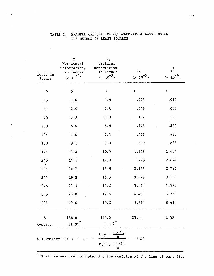
TABLE 2. EXAMPLE CALCUIATION OF DEFORMATION RATIO USING THE METHOD OF LEAST SQUARES
Load, in Pounds
0
25
50
75
100
125
150
175
200
225
250
275
300
325
Average
x, Horizontal
Deformation, in Inches (x 10-4)
0
1.0
2.0
3.3
5.0
7.0
9.1
12.0
14.4
16.7
19.8
22.3
25.0
29.0
166.6
* 11. 90
Y, Vertical
Deformation, in Inches (x 10-3)
0
1.5
2.8
4.0
5.5
7.3
9.0
10.9
12.0
13 .5
15.3
16.2
17~6
19.0
134.6
* 9.614
Ue[ormation Ratio = DR = Lxy _ Lx Ly
n
n
XY X2
(x 10-5) (x 10-6)
0 0
.015 .010
.056 .040
.132 .109
.275 .250
.511 .490
.819 .828
1.308 1.440
1. 728 2.074
2.255 2.789
3.029 3.920
3.613 4.973
4.400 6.250
5.510 8.410
23.65 31.58
6.49
These values used to determine the position of the line of best fit.
17
18
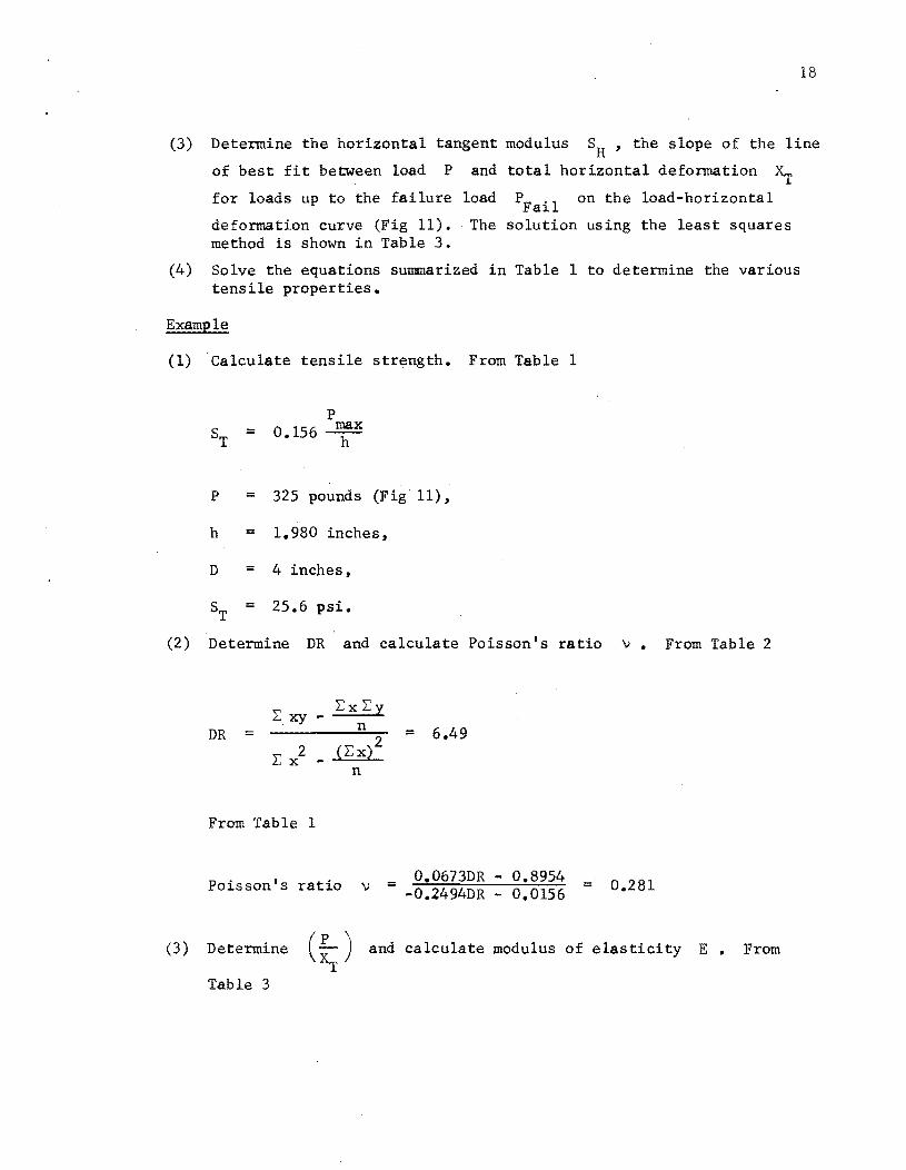
(3) Determine the horizontal tangent modulus SH' the slope of the line
of best fit between load P and total horizontal deformation Xr for loads up to the failure load PFail on the load-horizontal
deformation curve (Fig 11). The solution using the least squares method is shown in Table 3.
(4) Solve the equations summarized in Table 1 to determine the various tensile properties.
Example
(1) Calculate tensile strength. From Table 1
=
P =
h =
D =
=
P 0.156 u:x
325 pounds (Fig 11),
1.980 inches,
4 inches,
25.6 psi.
(2) Determine DR and calculate Poisson's ratio v. From Table 2
L:xy- L:xL:y n DR =
L:} - {L: xi2
n
From Table 1
Poisson's ratio v =
= 6.49
0.0673DR - 0.8954 -0.2494DR - 0.0156 = 0.281
(3) Determine (~ ) and calculate modulus of elasticity E. From T
Table 3

19
TABLE 3. EXAMPLE CALCULATION OF HORIZONTAL TANGENT MODULUS USING THE METHOD OF LEAST SQUARES.
X, Horizontal
Deformation, Y, XY X2 in Inches Load, in (x 10-4 ) Pounds (x 10-2 ) (x 10-6)
0 0 0 0
1.0 25 .250 .010
2.0 50 1.000 .040
3.3 75 2.475 .109
5.0 100 5.000 .250
7.0 125 8.750 .490
9.1 150 13.650 .828
12.0 175 21.000 1.440
14.4 200 28.800 2.074
16.7 225 37.575 2.789
19.8 250 49.500 3.920
22.3 275 61.325 4.973
25.0 300 75.000 6.250
29.0 325 94.250 8.410
L 166.6 2275 398.575 31.583
* Average 11.900 162.5
I. xy - Lx L:y
SH = n = 10.87 x 10⁴ 1b/in 2 0:: x)2
LX - n
"I( These values are used to determine the position of the line of best fit.

Exy _ ExEy n
2 (Ex)2 = 10.87 X 10⁴ 1b/in
Ex - - -n
From Table 1
E = S: [0.9976V + 0.2692J = 4 3.017 X 10 psi
(4) Calculate total tensile strain at failure ~T. From Fig 11
~ = .0029 inches
From Table 1
= rO.1l85v + 0.03896J = €T ~F LO.2494v + 0.0673
20

21
REFERENCES
1. Hadley, William 0., W. Ronald Hudson, and Thomas W. Kennedy, "Evaluation and Prediction of the Tensile Properties of Asphalt-Treated Materials," Research Report 98-9, Center for Highway Research, The University of Texas at Austin, October 1971e
2. Texas Highway Department, Manual of Testing Procedures, Vol I, Materials and Test Division, Test Method Tex-206-F, Revised Edition, 1966.
3. Hudson, W. Ronald and Thomas W. Kennedy, "An Indirect Tensile Test for Stabilized Materials," Research Report 98-1, Center for Highway Research, The University of Texas at Austin, January 1968.

APPENDIX 1
GENERAL - SPECIAL EQUIPMENT REQUIRED TO OBTAIN TENSILE STRENGTH

Die Space Left Front
to to Right, Back
in. in. A B
15% 6
• G t I
F -,
• E i t
I I
I
~- (:) ,-, , , '0' '0 1 I -t- ,
1 I , , " -' , -'
-1 BaR
-~ 1 ..... '------ A a H--~ .. I
Die Set - Top View
~ c
T Die Set - Front View Guide Post
Thickness Guide Post
Die Hldr,
In.
J
10/8
Punch General Le~th Press Shank
Hldr, Dimensions, Diameter, of r-ength
Fit Dimensions,
in. in. Press in. . , In. in. Fit, in. In.
K 0 H I R 0 P C L M E F G
13h 112!4 15%1 6 I~ I~ 13,4 I 10 .002 I~ 1 3
--~
(I) Guide Posts are Hardened, Ground, and Hard Chrome Plated to Listed Diameter within Tolerance of +.0003 in. to - .0000 in.
(2) ThomSon interchangeable Die Set Ball Bushings Number OS - 20
Fig AI. Die set s.pecifications.
Die Set Ball
Bushing (2)
Working Bore
Nom Tal.
I~ ~ 1.2500
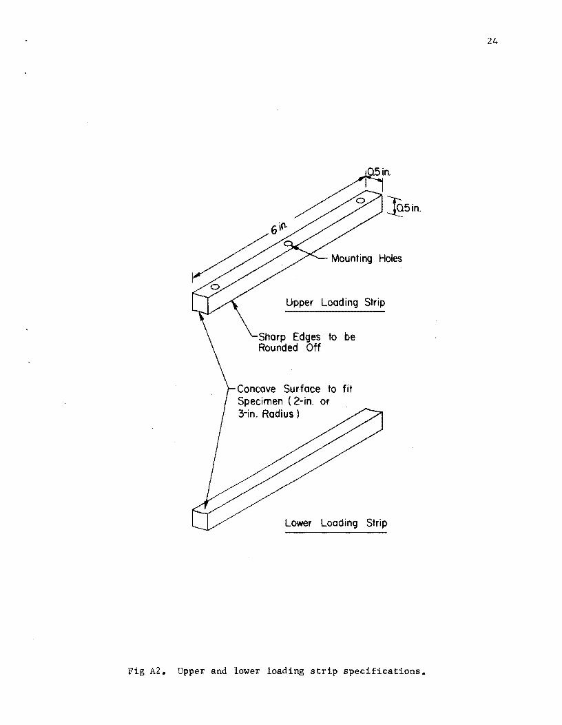
Upper Loading Strip
to be
Concave Surface to fit Specimen (2-in. or 3-in. Radius)
~5in.
Lower Loading Strip
Fig A2. Upper and lower loading strip specifications.
24
APPENDIX 2
TEXAS HIGHWAY DEPARTMENT - SPECIAL EQUIPMENT REQUIRED TO OBTAIN TENSILE STRENGTH

APPENDIX 2. TEXAS HIGHWAY DEPARTMENT - SPECIAL EQUIPMENT REQUIRED TO OBTAIN TENSILE STRENGTH
In order for the Texas Highway Department motorized gyratory press to be
utilized as the loading device, an upper and lower loading plate with the
* correct face curvature must be constructed and attached. The plate specifi-
cations are presented in Fig A3 and the loading strips are shown in Fig A4.
An additional modification of the gyratory press is required in order to
obtain accurate load estimates from the pressure gage. A Whitey Ball Valve
(Cat. No. 4354) and a Nupro Check Valve (Cat. No. B-4CA-3), both with l/4-inch
Swagelok inlet and outlet connections, should be inserted into the hydraulic
pressure line leading to the pressure gages as illustrated in Fig AS. Since
there is a time lag between the actual pressure and the indicated pressure,
this modification holds the actual pressure in the system allowing the pres
sure gage to catch up. In addition this modification eliminates the need of .
using the drag hand which is a definite source of error. ·Nevertheless, the
gage needles should be visually tracked during testing.
Extreme care must be taken in aligning the upper and lower loading plate.
26

Holes Drilled to Fit Bolt Holes on Platen of Gyratory Compactor
27
.~. Note: 0) 'l Both Loading Strips
are 0.5 in. )( 0.5 in. )( 9 in. a are Mounted with 3 Socket
Head Screws. All Screws are Countersunk to Avoid Inter
ference on Back Side of Plate. One Pair of Loading Strips is
Machined to Fit 4-in:-Diameter /, Specimen, Second. Pair to
. ~s . Fit 6-in:- Diameter ~ '" / /-? ~specimen
/ "'-
, /
(;) . i~' / '- It/
Fig A3. Upper and lower loading plate specifications.
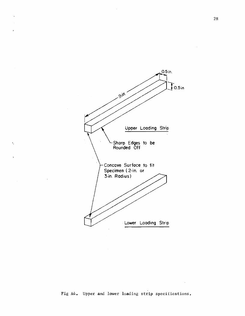
}O.5in
Upper Loading Strip
Sharp Edges to be Rounded Off
Concave Surface to fit Specimen (2-in. or 3~n. Radius)
Lower Loading Strip
Fig A4. Upper and lower loading strip specifications.
28

"
,I.,u. 1IDd1f1""u- of ........ ,. _. oJ"" I. , , " " uto'7 .r ... .

APPENDIX 3
SPECIAL EQUIPMENT REQUIRED TO DETERMINE POISSON'S RATIO, MODULUS OF ELASTICITY,
AND TENSILE STRAIN AT FAILURE

APPENDIX 3. SPECIAL EQUIPMENT REQUIRED TO DETERMINE POISSON'S RATIO, MODULUS OF ELASTICITY, AND TENSILE STRAIN AT FAILURE
The special equipment required to determine the various tensile parameters
is as follows:
(1) a loading device capable of applying compressive loads at a controlled deformation rate of 2 inches per minute;
(2) a guided loading head with parallel platens, such as a commercially available all-steel precision die set (Fig Al);
(3) a pair of curved-face loading strips of the proper size, which are to be attached to the upper and lower platens of the die set (Fig A2);
(4) a rear platform with a polished surface to be attached to the rear of the lower platen of the die set to support the horizontal deflection device (Fig A6);
(5) a horizontal deformation measuring device (Figs A7, AS, A9, Ala, and All) ;
(6) a calibrator for the horizontal deformation device (Fig A12), the dimensions for which are presented in Fig A12;
(7) an LVDT (linear variable differential transformer), such as Schaevitz Engineering Type 1000 DC-LVDT, to measure vertical deformation;
(B) a load cell to measure the applied load;
(9) three DC power supplies, such as Hewlett-Packard Model B01C, to power the load cell, the horizontal deflection device, and the LVDT;
(10) two x-y plotters, such as Hewlett-Packard Model 700LA, to continuously record load and vertical and horizontal deformation;
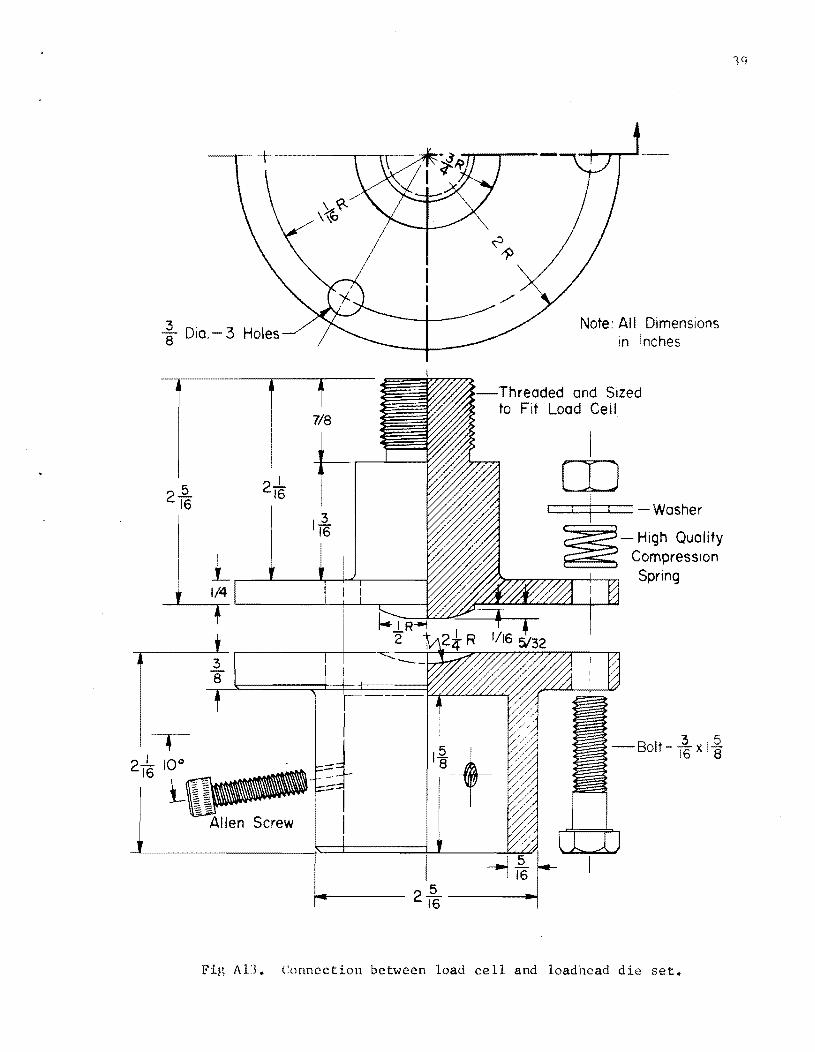
(11) a load cell to die set connector (Fig A13); and
(12) a digital voltmeter with which to set the various voltage requirements.
All of the above equipment except items 1, 6, 9, la, and 12 is shown in
Fig 9, arranged in a testing mode.
31

Polished Surface
Fig A6. Rear platform to support horizontal deformation device.
32
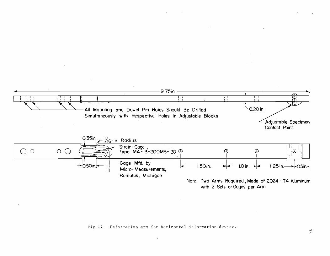
~.~~-------------------------------------------------9.75in.------------------------~--------------------~
I I , , , , , ,
'---"-----"'-------"-- All Mounting and Dowel Pin Holes Should Be Drilled Simultaneously with Respective Holes in Adjustable Blocks
0.20 in.
00 00
Adjustable Specimen Contact Point
0.35in., Yl6-ln Radius .., t r I
( ~ Strain Gage, ~. 1 I I
L ) Type MA -13-200MB-120 (±) (!1 (±) ! :~::';I 'I ~ f L: I I I . ~ I I:
-b50irl.~- G~ge Mfd. by !----1.50in.---...... 14....--1.0 in.--.I"'--1.25in.---+0.5in.~ Mlcro- Measurements, Romulus, Michigan
Note: Two Arms Required, Made of 2024 - T4 Aluminum with 2 Sets of Gages per Arm
Fig A7. Deformation arm for horizontal deformation device. w w

~o.486 l.I In. I
t II t I I It 11 I I I II I
OI25.in.~I: II . ~: :(Q): ::
r-~ II 0 t
~ r-' : :: :: In ,- I , " I I I, ' .-::1,1 11 1111', '-I' I I I '''::-' '_JI II II I :
::.:J ~,
Note: . To Be Mode of Aluminum
-' r=: q.7 in., Drilled and ::: ilTappedto fit '-I' ~ 3116,32 tpi Screw
I 1 1 i 1 IIO.2in. JL.......!...... -=------'---'---:1
1-----1.75in.---
I,'ig i\1:l. Coarse adjustment block for horizontal deformation device.

Locking Lug
Iii ; 1 I
Note:
(I) General Dimensions, Dowel Pin Locations, and Arm Mount Screw Holes on Both Blocks are the Same.
(2) Rack and Pinion Device can be Selected from Availability of Parts and Installed to Bu i Iders Specifications.
(3'> To Be Mode of Aluminum
/' Set Screw to Hold Rack a and Pinion Bushing , ,------------
~10 00 §:_-,.::.1 ___ I: L ________ __ .,
,..::.,
:1:1-:1:1:1 p!i: I ~~!\.~-l.~4.J11I71 --- ... :-:.: ... -...
I ' I I
35
- - - - - - ' .... _,' - - - - - -
(To Accom modate Brass Locking Plate)
,-, -~
,~ ,_,
Fig A9. Fine adjustment block for horizontal deformation device.
,-, -'

\ \ I ,-,
-------- - - --------- ---~Threaded Holes for (\ : u ~oorse Adjustment ~ I
_B~o£k _ L.QC.!<i!l9_ S£r~ _ _ _ _ _ _ _ _ _ -! __
o r- 1
~ I
For Coble Clomp Screw
in. -- .......... ~--~~
1_--1 I-=-'I I-=:-, L=.J I - I
I~ . - . 1-::-. L";:-...I
"- Drill 4 Holes to Accommodate
,- " I \
" -'
Rock
o Set Screws to Lock Gear Rock in Place
r --, ;.....:=-: "---1 ........=-. 1'-::-'
r - -1 l..-:::...-t I I :-=-1 I 1 ,_.:..-1
1 - 1
Low Friction Skid Pads (Teflon, to be Press Fit)
Note: To Be Mode of Aluminum
1.75 in .
1 r-, , • I
r" - ~ 1
• 1
f..4----- 2.0 in.--~
F AIO. Base for horizontal deformation device.

@
~--- 2.25 in.----.-!
I.... .: I ........ _" I I I
I ,..l __ l., r--,
I I I I: I '-Skid Pad
2.0 in.
I 1.0 in.
I
Note: To Be Made of Aluminum
Drill Relief Holes For Main Base Pads
I , r ~ - _1.-, I I
I I I
,.. --, I I ,
3/
~TO fit Socket Head Screw for Bolting to Main Base
Fig All. Base extension for horizontal deformation device.
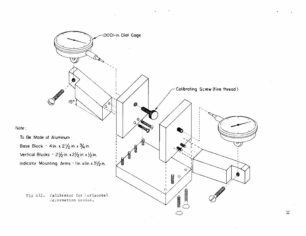
.OOOI-in. Dial Gage
Note:
To Be Made of Aluminum
Base Block 4 in. x 2 Y2 in. x 3,4 in.
Vertical Blocks - 2!h in. x 2 V2 in. x V2 in.
Indicator Mounting Arms - lin. xlin)( 3V2in.
F A12. Calibrator for horizontal deiormation oevice.
... , ........ ,
~ Dia. - 3 Holes
7/8
f-.------'-------5
216 21~ I
I
Note: All Dimensions in Inches
-Threaded and Sized to Fit Load Cell
I CD
i I : I - Washer
- High Quality Compression Spring
Fig AU. Connection between load cell and loadhead die set.

APPENDIX 4
HORIZONTAL DEFORMATION DEVICE CALIBRATION

APPENDIX 4. HORIZONTAL DEFORMATION DEVICE CALIBRATION
Calibrate the horizontal deformation device as follows:
(1) Plug in DC power supply and recording equipment and allow approximately 20 minutes for warmup.
(2) Adjust DC power supply output to approximately 6 volts. A digital voltmeter is preferred for this adjustment.
(3) Place horizontal deformation device in calibrating position (Fig A14). Arm contacts should be centered on actuating screws and dial gage points. Caution should be exercised to assure that the arm contact points are lightly in contact with the actuating screw holder blocks.
(4) Lock arms in the above position.
(5) Connect the device to the power supply and to the recording equipment.
(6) Null the strain gage output and zero the dial gages.
(7) Select the desired MV/inch range on the recorder.
(8) Using one of the arm activating screws of the calibrator, move the arm a given amount. Check for proper movement on the recording equipment. The amount of movement may be changed by altering the applied voltage to the strain gage or by altering the range selection of the recording equipment.
(9) Calibrate the other arm in a like manner.
(10) Continue the process several times to check for repeatability.
41

42
Fig A14. Horizontal deflection dev ice and calibrator.

THE AUTHORS
James N. Anagnos is a Research Engineer Associate with
the Center for Highway Research at The University of Texas at
Austin. He has had experience as a laboratory supervisor
with the Texas Highway Department, as an engineer for nuclear
moisture density equipment with Lane Wells Company of Houston,
and as a plant quality control engineer with the Texas Crushed
Stone Company of Austin. His current research activities involve asphalt, lime,
and cement stabilization; compaction studies; tensile testing of asphaltic con
crete; and load transfer characteristics of drilled shafts and piles.
Thomas W. Kennedy is an Associate Professo'r of Civil
Engineering at The University of Texas at Austin, His exper
ience includes work with the Illinois Division of Highways and
at the University of Illinois and the Center for Highway Re
search at The University of Texas at Austin. He has done ex
tensive research ' in the areas of (1) highway geometries,
(2) concrete durability, (3) tensile strength of stabilized subbase materials,
and (4) time-dependent defamation of concrete "and has contributed numerous
publications in the field of transportation engineering. He is a member of
several professional societies and has participat:ed in coounittee work for the
Highway Research Board and the American Concrete Institute.
43