ppower fence systemsower fencetm systems manual · pdf file · 2016-09-056 where to...
TRANSCRIPT

ManualPower Fence SystemsPower Fence SystemsTM

PUBLISHED BYGallagher Group Limited181 Kahikatea Drive, Private Bag 3026Hamilton, New Zealand
www.gallagherams.comCopyright© Gallagher Group Limited 2008All rights reserved. Patents pending.
Gallagher Power Fence Systems User Manual
3E1164 - Edition 17 - February 2012
DISCLAIMER: Whilst every effort has been made to ensure accuracy, neither Gallagher Group Limtted nor any employee of the company shall be liable on any ground whatsover to any party in respect of decisions or actions they may make as a result of using this information.
In accordance with the Gallagher policy of continuing development, design and specifications are subject to change without notice.
Developed and manufactured by Gallagher Group Limited, and ISO 9001 2000 Certified Supplier.

Table of ContentsIntroduction ......................................................................................................5
1. Reasons for Using Power Fencing .................................................................6
2. How does Power Fencing Work? ..................................................................6
3. Where to Start .............................................................................................73.1 Permanent Power Fence: ......................................................................73.2 Portable Power Fence: .........................................................................8
4. Installing a Permanent Power FenceTM ..........................................................94.1 Planning the fence layout .....................................................................9
4.2 Selecting the correct energizer ...........................................................13
4.3 Installing the Energizer .......................................................................18
4.4 Fence Construction ............................................................................23
5. Installing a Portable Power FenceTM..................................................................35
5.1 Planning the fence layout ...................................................................35
5.2 Selecting the correct Energizer ...........................................................36
5.3 Fence Construction ............................................................................39
6. Fault Finding ............................................................................................. 40
6.1 Fence tools and testers ...................................................................... 40
6.2 Troubleshooting ................................................................................ 40
6.3 Induction .......................................................................................... 40
6.4 Repairs ............................................................................................. 40
7. Stock Control.......................................................................................................42
7.1 Training stock to respect Power FencingTM ..........................................42
7.2 Training dogs to work around Power FencesTM ...................................42
7.3 Feral (wildlife) Fencing ........................................................................42
7.4 Equine Fencing ...................................................................................42
8. Safety Requirements and Regulations..............................................................43
8.1 Warning signs ....................................................................................43
8.2 Radio interference .............................................................................43
8.3 Telephone interference ......................................................................43
9. Glossary...............................................................................................................48
9.1 Electrical Terms ................................................................................. 48
9.2 Power Fencing Terms .........................................................................49

4
Gallagher 3E1164 Power Fence Systems User Manual
INTRODUCTIONThe earlier generations of Gallaghers were farmers. And it was a typical farmer’s approach to solving farm problems that helped us lead the world into the electric fencing age. From the 1930’s we developed, on our own family farm, animal control systems to make farm work easier. Today we are known in over 100 countries.Gallagher Power FenceTM Systems are recognised for decreasing costs and increasing profits for farmers throughout the world. Our economical and practical fencing provides increased efficiency in controlled grazing through subdivision. Increased stocking rates and fodder conservation are the prime contributors to better farm profits and farmers have reaped the benefits of upgrading non electric fences, fencing out wild animals and protecting both stock and pasture.
This manual is designed to help you achieve the best possible results from your Gallagher Power FenceTM System. It will help you design your fence system and give suggestions for the fence materials, hardware, accessories, tools and testers you will need. For maximum power with minimum maintenance it is important to follow the principles of fence construction and energizer earthing closely. If you’re not prepared to do it properly, be prepared to accept less than optimum performance.
Thank you for choosing Gallagher - I’m sure you’ll be satisfied with your decision for years to come.
W.M. Gallagher KNZM, MBE. Hon D
Chairman and Chief ExecutiveGallagher Group Ltd

5
Gallagher 3E1164 Power Fence Systems User Manual Reasons for Using Power Fencing
1. REASONS FOR USING POWER FENCINGAnimal Control
• Keep domestic animals in.
• Keep wild animals and vermin out.
• Separate different groups of animals.
• Allow rationing of crops and pastures.
• Fence off eroding areas, trees, rivers and roads.
The Benefi ts of Power Fencing
• Affordable.
• Easily constructed and maintained.
• Light weight and easily transported.
• Durable because of low physical contact.
• Easily modified.
• Less animal hide and pelt damage.
• Deterrent to trespassers and predators.
Profi tability
• Increase milk and meat production with fresh, short, highly palatable pasture.
• More subdivision ensures animal manure is spread more evenly over the whole grazing area.
2. HOW DOES POWER FENCING WORK?A power fence is a psychological barrier that keeps farm animals in and wild animals and vermin out – even over long distances.
A pulsed electric current is sent along the fence wire, about one pulse per second, from an energizer which is earthed. When the animal touches the fence it completes the circuit between the fence and the ground and receives a short, sharp but safe shock. The shock is sufficiently memorable
that the animal never forgets. If the ground is very dry, the fence may require an earth return wire (see Figure 4.7(b)).
A power fence is a psychological barrier so doesn’t need great physical strength. However, it must be well designed and constructed to absorb some pressure from animals, snow and wind. The energizer must have enough power for the length of fence and for the animals being controlled.
Figure 2.1

6
Gallagher 3E1164 Power Fence Systems User ManualWhere to Start
�
�
�
�
��
�
�
�
3. WHERE TO STARTUnless you want a temporary or removable fence, a permanent power fence will be the best choice. Permanent power fencing is economical and easy to install and operate. Portable power fencing is an effective temporary barrier for short-term animal control and rotational grazing. Here are the basics for permanent and portable fences.
The question we are asked the most is “where do I start?” This manual is the first step to choosing the fence that’s right for your needs and property. The more you know before you start, the easier and more economical your fence installation will be.There are two types of fence, permanent and portable, and three ways to power them: mains, battery and solar/battery.
3.1 Permanent Power Fence:
Here’s what you’ll need:
• Electric fence energizer
• Earth (ground) system
• Leadout cable
The fence itself:
• End strain insulators
• Line post insulators
• Joint clamps
• Cut out switches
• Electrified gates
• Wire tighteners
• Posts
• 2.5mm high tensile galvanised wire
• Staples
• Offset brackets (optional)
Refer to “4. Installing a Permanent Power Fence” for information on how to install a permanent power fence.
Figure 3.1(a) - Permanent Cattle Fence
�
�
�
��
�
�
��
Figure 3.1(b) - Permanent Cattle Fence with Earth Return Wire
A Energizer
B Earth stake
C Strain insulator
D Post insulator
E Wire tightener
F Warning sign
G Green
H Red
I Cut out switch
J Joint clamps
K Strain post
L Line post

7
Gallagher 3E1164 Power Fence Systems User Manual Where to Start
3.2 Portable Power Fence:
Here’s what you’ll need:
• Electric fence energizer
• Battery
• Earth (ground) system
• Reels
• Polytapes, wires or braids
• Portable fencing posts
• Connector leads
• Insul-grips
Refer to “5. Installing a Portable Power Fence” for information on how to install a portable power fence.
�
� � � �
�
�
A Reel
B Polywire/Turbo Wire
C Treadin Post
D Insul-grip
E Pigtail post
F Energizer
G Earth stake
H Red
I Green
Figure 3.2 - Portable Fence
Sheep fence Cattle fence

8
Gallagher 3E1164 Power Fence Systems User ManualInstalling a Permanent Power FenceTM
4. INSTALLING A PERMANENT POWER FENCETM 4.1 Planning the fence layout
Draw a plan of the fence system you would eventually like to have. This will help you identify the length of new electric fence, the length of existing fence to be electrified (using offsets) and the length of leadout from your energizer to the electric fence. On the plan show the power supply, the direction the power flows, gateways and cutout switches and electrification of remote areas. Allow for two or more sections to be electrified by a separate energizer in the future. You might also need a training paddock for livestock. If your electric fence system is several kilometres (miles) from the mains power supply, see “Electrifying Remote Areas” under section 4.4.1 Install the Leadout for more information.
Figure 4.1 shows an ideal layout on a flat rectangular farm. Use the same principle
on all properties whatever the shape or size. It is the number of paddocks that is important not the size. Plan the number of paddocks to allow for controlled grazing, easy conservation of hay/silage and long rotations in times of slow pasture growth.
Make a lane, race or roadway down the centre or side of the area to be subdivided or fenced. This allows stock to be checked and moved easily. If necessary, water pipes can be laid down the lane. Paddocks should be as close to square as possible for even grazing. Long narrow paddocks create footpaths with overgrazing at the front and undergrazing at the back.
Avoid having electric wires running parallel with telephone and power lines (refer to “8. Safety requirements and regulations”).
Figure 4.1 - Ideal fence layout
Cut-out switch
Energizer

9
Gallagher 3E1164 Power Fence Systems User Manual Installing a Permanent Power FenceTM
HANDY HINT
Rough, stony or steep areas:
With power fencing it is easier and less expensive to “zig zag” around rather than go straight over rough, stony or steep areas. These rough areas require more posts and tie-downs, and possibly more maintenance in the future.
If possible level the area first and re-grass the area because animals standing on grass get a greater shock than when standing on bare soil. Re-grassing also prevents erosion and weed growth.
Stock will respect all fences if most of your farm fences are electrified. This means internal subdividing fences can then have fewer wires so you can build more fencing at a lower cost per metre (yard). Power fencing also makes fencing dams, rivers, trees and erosion prone areas easier.
Cut Out Switches (G6076/G6087):
These isolate different sections of the fence when looking for faults. Place them at gateways or junctions where either single or multiple fence lines can be turned off.
If you farm sheep intensively, you may want as many as 100 paddocks. This means the sheep can be moved daily onto a fresh paddock using a three month rotation during slow or zero growth periods. When there are lambs and ewes during spring, two or more flocks can be grazed on a faster rotation.
On dairy farms 30–50 paddocks are usually enough. Cattle are easy to strip graze with only one wire when longer rotations are necessary during slow growth periods.
HANDY HINT
HANDY HINT

10
Gallagher 3E1164 Power Fence Systems User ManualInstalling a Permanent Power FenceTM
Wire and post spacings
The figures are guidelines only for flat country conditions.
symbol indicates a live, pulse-carrying wire
symbol indicates an earth (ground) wire
750mm (30")
All Live
450mm (18")
450mm (18")
450mm (18")
450mm (18")
All Live Earth Return Wire
All Live Earth Return Wire
250mm (10")
700mm (28")
250mm (10")
250mm (10")
700mm (28")
250mm (10")
All Live Earth Return Wire
900mm(36")
1200mm(48")
Post spacing 20 - 30 m (60 - 90 ft)
300mm (12")
300mm (12")
900mm(36") 300mm (12")
300mm (12")
300mm (12")
Post spacing 20 - 30 m (60 - 90 ft)
Dairy Cows / Beef Cattle
Horses
300mm (12")
Post spacing 20 - 25 m (60 - 75 ft)
Post spacing 20 - 25 m (60 - 75 ft)
Dairy Cows / Beef Cattle
Dairy Cows / Beef Cattle
Figure 4.2a

11
Gallagher 3E1164 Power Fence Systems User Manual Installing a Permanent Power FenceTM
Post spacing 15 m (50 ft)
All Live Earth Return Wire
Post spacing 6 m (20 ft)
All Live Earth Return Wire
250mm (10")
150mm (6")
250mm (10")
150mm (6")
150mm (6")
250mm (10")
150mm (6")
250mm (10")
150mm (6")
150mm (6")
All Live Earth Return Wire
250mm (10")
150mm (6")
200mm (8")
150mm (6")
250mm (10")
150mm (6")
200mm (8")
150mm (6")
All Live Earth Return Wire
750mm(30")
950mm(38")
1.5m(59")
Post spacing 15 - 30m (45 - 90 ft)
420mm(16 ½")
125mm (5")
90mm (3 ½")
90mm (3 ½")
115mm (4 ½")
125mm (5")
90mm (3 ½")
90mm (3 ½")
115mm (4 ½")
250mm (10”)
250mm (10”)
250mm (10”)
150mm (6”)150mm (6”)150mm (6”)150mm (6”)150mm (6”)
Pigs (wild)
Sheep / Goats
Rabbits
Deer (for crop protection)
Post spacing 8 - 10 m (25 - 30 ft)
250mm (10”)
250mm (10”)
250mm (10”)
150mm (6”)150mm (6”)150mm (6”)150mm (6”)150mm (6”)
Figure 4.2b

12
Gallagher 3E1164 Power Fence Systems User ManualInstalling a Permanent Power FenceTM
4.2 Selecting the correct energizerThe energizer is the heart of the fencing system so select carefully. Gallagher energizers guarantee a high-energy pulse that will effectively control animals even over long distances. They are identified by their stored energy (measured in joules) e.g. M1200 has approx. 12 stored joules, MBX2500 has approx. 25 stored joules.
When choosing an energizer, compare the stored energy figure. Stored energy is the most accurate measure of an energizer’s capability because it is constant and not affected by external conditions like poor earthing.
Electric fence systems tend to grow, so purchase an energizer that will power the final fencing system. There is a range of Gallagher energizers (also called units, controllers, chargers or fencers) for all situations.
Mains powered energizers are the best choice where you have reliable mains power. Mains/battery powered energizers like Gallagher SmartPower MBX energizers combine the advantages of mains power with a battery backup. They are a practical
choice for providing guaranteed animal control and a must in regions where mains power is unreliable.
Solar powered battery energizers are the logical choice for remote areas where there is no mains power. A solar panel charges a deep cycle battery by converting light directly into electricity. The battery stores this electricity to operate the battery powered energizer. This enables the energizer to operate at night or during periods of low sunlight. The brightness, the amount of light and the size of the solar panel all determine how much electricity is produced.
Note: Solar systems require individual designs for different locations. Contact your Gallagher dealer for advice.
Portable battery powered energizers are generally operated by a 12 volt rechargeable battery or a 9 volt disposable dry cell battery.
The B11 battery powered strip grazer is designed for single reel systems and can be operated by 6 “D” size batteries or a 12 volt rechargeable battery.
Stored energy versus output energy?
Stored energy: Power from either a mains power source or a battery enters the energizer and is stored in capacitors as stored energy. The higher the stored energy figure the more powerful the energizer.
Output energy: A timing circuit in the energizer sends the energy down the fence line approximately once a second through a transformer as output energy. Output energy can vary depending on fence conditions and national standards.
Batteries: Where a rechargeable battery is used to power the energizer, the battery will need to be recharged as necessary depending on the size of the energizer, battery capacity and amount of use. So choose a battery that withstands regular charge and discharge cycles without damage – such as a marine or deep cycle type. We do not recommend using automotive batteries because they are designed to supply very high current for only a short time.
ENERGIZER FACTS

13
Gallagher 3E1164 Power Fence Systems User Manual Installing a Permanent Power FenceTM
For a permanent power fence system choose from a mains powered energizer, a mains/battery powered energizer or a permanent solar powered energizer.Energizer selection is determined either by acreage to be fenced or the length of fence.
Both are estimates because the distance of fence can vary between two farms of the same area because of the number of paddocks, terrain or conditions. For dry country conditions, energizers have proven to work effectively over greater distances.
Energizers that display information should be installed where the information is easy to read.
Battery energizers, including solar, are best placed in the centre of the fence line and protected from animals.
Keep them off the ground to protect the electronic components from insects and moisture.
Figure 4.3* A combination of Energizers may be required.** Gallagher recommends 2.5 mm high tensile galvanised wire.All Gallagher energizers carry a 2 year warranty and have a 30 day trial period.
Energizer Selection Chart - by Farm Size
Size of Property Energizer Type Beef/Dairy/Horses Bulls/Sheep/Goats/Pigs/Deer
0-4ha. (0-10 acres) PowerPlus Mains FenceMasterPowerPlus Solar
M150/M300M100B80
M600
B180
0-10ha. (0-25 acres) SmartPower PowerPlus Mains PowerPlus Solar
MBX1500 M300 B180
MBX1500 M600 B280
0-20ha. (0-50 acres) SmartPower PowerPlus Mains PowerPlus Solar
MBX1500 M600 B280
MBX1500 M1200 B700
0-40ha. (0-100 acres)
SmartPower PowerPlus Mains PowerPlus Solar
MBX1500 M1200 B700
MBX1500 M1800 2 x B700 or 1 x B1600
0-60ha. (0-150 acres)
SmartPower PowerPlus Mains PowerPlus Solar
MBX1500 M1800 2 x B700
MBX2500 MR2500 B1600
0-100ha. (0-250 acres)
SmartPower PowerPlus Mains PowerPlus Solar
MBX2500 MR2500 B1600
2 x MBX2500MR5000 2 x B1600
0-160+ha. (0-400+ acres) *
SmartPower PowerPlus Mains
PowerPlus Solar
MX7500 MR6000MR5000 2 x B1600
MX7500 MR60002 x MR5000 3 x B1600
Number of internal fence wires++ 1 to 3 3 to 5
HANDY HINTHANDY HINT

14
Gallagher 3E1164 Power Fence Systems User ManualInstalling a Permanent Power FenceTM
Energizer Selection Chart - by Fence Distance (km)
Energizer Stored Energy(Joules)
Maximum Distance of Fence - (km)Gallagher Recommendations
(multi-wire fence)
High Vegetation
Average Vegetation
No / Low Vegetation
Ma
ins
SmartPower MX7500 75 24 40 160
SmartPower MBX2500 25 12 20 80
SmartPower MBX1500 15 8 15 60
PowerPlus MR6000 60 21 35 140
PowerPlus MR5000 50 20 30 120
PowerPlus MR2500 25 12 20 80
PowerPlus M1800 18 8 16 65
PowerPlus M1200 12 7 12 48
PowerPlus M600 6 4 9 35
PowerPlus M300 3 1.5 6 25
PowerPlus M150 1.5 • 3 13
FenceMaster 1 • 2 8
HobbyMaster 0.2 • • 2
Ba
tte
ry
PowerPlus B1600 16 8 15 60
PowerPlus B700 7 5 10 40
PowerBox B300 2.6 2 6 30
PowerPlus B280 2.8 2 8 35
PowerBox B200 1.45 1 4 20
PowerBox B180 1.7 1 6 25
PowerBox B100 0.8 0.75 2.5 12
PowerPlus B80 0.8 0.75 4 12
PowerPlus B40 0.38 0.5 1.5 6
PowerPlus B20 0.2 • 1 1.5
PowerPlus B11 0.11 • • 1
So
lar Solar S50 0.5 1.2 2.0 8.0
Solar S20 0.2 • 1.2 3.0
Solar S17 0.15 • 1.0 1.5
• Not recommended. Insufficient power for this application.
All Gallagher energizers carry a 2 year warranty and have a 30 day trial period
Figure 4.4

15
Gallagher 3E1164 Power Fence Systems User Manual Installing a Permanent Power FenceTM
Solar Powered Energizers
Solar panels convert light directly into electricity. The battery stores this electricity and operates the battery powered Energizer. This allows the Energizer to operate at night or during periods of low sunlight.
The brightness, the number of hours of light and the size of the solar panel all determine how much electricity is produced.
Contact your local Gallagher supplier for more information regarding solar options suitable for your area.
Solar Panel
Energizer
Mounting bracket
Figure 4.5 - Solar powered energizers

16
Gallagher 3E1164 Power Fence Systems User ManualInstalling a Permanent Power FenceTM
�� �
�
SmartPowerTM
The SmartPower range introduces new generation technology that makes power fencing much simpler, more efficient and more reliable for you. Gallagher SmartPower is easy to work and live with.
SmartPower MX7500 (G37710) MBX2500 (G302) MBX1500 (G300)
• New generation technology.
• MX7500 75 Joules stored energy.MBX2500 25 Joules stored energy.MBX1500 15 Joules stored energy.
• Mains powered with battery backup or battery only operation (MBX only).
• Four large easy-to-read digital displays show stored energy, output voltage, fence voltage, earth voltage.
• Remote controlled to switch the energizer on/off from anywhere on the fence line.
• Special features - battery backup (excluding MX7500), alarms, lightning protection.
• Auto-dialer compatible (MBX version only) (see Figure 4.6)
• Maximum distance of multi-wire permanent fence (no/low vegetation) MX7500 160km (100 miles), MBX2500 80km (50 miles), MBX1500 60km (40 miles).
SmartPower MBX Alarm Kit (G5695)
• Includes Alarm Controller (G56900), Siren (G56902) and Strobe (G56901).
• Includes security alarm features for monitoring a fence return loop. Alarms sound when the fence return loop is broken or shorted out (see Figure 4.6).
A Energizer
B Alarm Controller
C Siren
D Strobe Lamp
E Earth Stake
F Reference EarthReturn loopAlarmed section
Figure 4.6 - SmartPower alarm kit

17
Gallagher 3E1164 Power Fence Systems User Manual Installing a Permanent Power FenceTM
(reference earth) installed close to the energizer with a separate wire or cable connected back to the energizer earth monitor terminal. This enables the energizer to continuously monitor the performance of the earth system.
Location of the earth system
The most effective place for the earth system is in continuously damp, high mineral soil.
• At least 10m (33ft) from an electrical or telephone earth (the further away the better)
• At least 10m (33ft) from metal pipes carrying domestic or stock water
• At least 20m (66ft) from any dairy shed pipework
• Not connected to, or touching steel or iron clad buildings
• Protected from machinery and stock damage
• Away from fertiliser, animal urine and manure (corrosion)
If the earth system has to be some distance from a high powered energizer the connecting wire must be highly conductive e.g. 250 m (820 ft) away use 1 x aluminium coated wire (G9290), 500 m 1640 ft) away use 2 x G9290 wires in parallel.
4.3 Installing the Energizer4.3.1 Install the earthing (grounding) system
Why does the energizer need an earth system?
The earth is half the circuit of your fencing system. Electrons travel from the energizer, along the fence wires and back through the ground to the energizer to complete the circuit. Like a radio antenna collects sound waves, the earth system collects the electrons. The earth must be as conductive as possible for the fence to give the animal an effective shock. A simple guide is one earth stake for every five joules of stored energy with a minimum of three earth stakes e.g. M1200 (12 joules) - three stakes , MR5000 (50 joules) - ten stakes. In sandy or pumice soils more stakes will be required.
Energizer Size Earth stakes required
Up to 15 J 3 Stakes minimum
Up to 25 J 5 Stakes minimum
Up to 35 J 7 Stakes minimum
Figure 4.7 - Earth stakes requiredIt is important to follow the recommendation above to get the maximum benefit. The number of earth stakes will vary depending on the power of the energizer and the soil type: high powered energizers need more stakes than low powered energizers, dry soils need more stakes than wet soils.
4-3-2-1 Rule for Earth stakes :4 Metres between earth stakes3 Earth stakes minimum required2 Metres min. length of earth stake1 Wire connecting all earth stakes
Note: Some modern energizers with earth monitors, e.g. SmartPower energizers, require a small independent earth stake
WARNING:Use galvanised earth stakes. Rusty or corroded stakes will not work.
Do not allow bare wires to touch an iron clad building - use double insulated cable.
HANDY HINT

18
Gallagher 3E1164 Power Fence Systems User ManualInstalling a Permanent Power FenceTM
a) All live wire system (for areas with good grounding systems)
The animal must touch the wire and the earth to feel a shock
Live
Live
LiveEarth Clamp (G8760)
Earth Stake (G8790)
Red
Green
Figure 4.7(a)
Figure 4.7(b)
Live
Earth
LiveEarth Clamp (G8760)
Earth Stake (G8790)
Red
Green
The animal must touch both a live wire and the earth wire to feel an affective shock
The top and bottom wires are electrified and the middle is the earth wire
b) Earth wire return system (for areas with poor grounding systems)
Earth (ground) wire return system
Dry soils have poor conductivity. For year-round dry, frozen or snow conditions an earth wire return system should be used in conjunction with the earth system.

19
Gallagher 3E1164 Power Fence Systems User Manual Installing a Permanent Power FenceTM
Super Earth Kit
In dry, low mineral soils with poor earthing, eg. sandy, pumice or volcanic ash soils, use the Super Earth Kit (G8800).
Note: In drought conditions it may be necessary to water the earthing system.
4 wire earth return system
�����
Figure 4.8 - 4 wire earth return system
Main causes of a poor earth are:
• Rusty or corroded earth stakes
• Broken earth wire connecting the stakes
• Not enough earth stakes
• Stakes too close together or too short
• Poor connections at the stakes or in the connecting wire
Test the earth (ground) system
This needs to be done once a short section of fence has been built. It should be tested at least once a year or at the height of any dry period to ensure the earthing capacity is sufficient for the joule rating of the energizer.
Short the fence out at least 100m (330ft) away from the earth system by using several steel stakes between the live wires and the ground. Reduce the fence voltage at this point to 2000V (2kV) or less.
Using a Digital Volt Meter (DVM) (G5030 or G5035) measure the voltage between the wire connecting through the earth stakes to the energizer earth terminal and an independent earth stake. This stake should be a galvanised metal rod, minimum 200mm (8”) long, and placed one metre (3ft) away from the earth rods or as far away as your DVM cable will reach (see Figure 4.9).
Note: If you are using a SmartPower energizer the earth monitor/alarm will indicate when the earth system requires attention (see Figure 4.6).
There should be no reading on the DVM, however up to 200V (0.2kV) is acceptable. If the voltage is higher than this, switch off the energizer, drive in more earth stakes at the recommended spacings and connect them to the existing earth system until the voltage is down to the acceptable level.
���������
���������
��
������������
��� ���
Figure 4.9

20
Gallagher 3E1164 Power Fence Systems User ManualInstalling a Permanent Power FenceTM
Testing an earth (ground) return wire
Install a standard length earth stake (2.0m) as close as possible to the end of the fence. Install a 500 ohm load (G50600) between a live wire and the earth wire. Choose the location for the earth stake in a damp area if possible. If you cannot find a damp area, the earth test may be unreliable. Using a DVM measure:
1 The voltage between the live wire and the earth wire, (i.e. across the load just installed).
Figure 4.10(a)2 The voltage between the live wire and the
independent earth stake, leaving the load in place.
Earth Return Wire Performance
If the second voltage reading exceeds the first by more than 1000V (1kV) check the earth return wire for loose connections. Finally connect the independent earth stake to the earth return wire as a permanent connection. Extra earth stakes can be installed at various places around the fencing system and connected to the earth return wire to improve earth performance.
System Performance
If the first voltage reading is less than 3kV, your fence system is at risk of poor animal control. Assuming that your earth wire return checked out satisfactorily, check that the fence live wire has good connections. If connections are good, it is possible that your energizer is too small for your fence system. Assess your total length of fence or farm size against the energizer selection charts (see Figures 4.3, 4.4 and 5.2).
Note: Is your fence system one of the 80% that surveys show do not have an adequate earth system?
G503 or G509 G50600
G503 or G509 G50600
Figure 4.10(b)
21
Gallagher 3E1164 Power Fence Systems User Manual Installing a Permanent Power FenceTM
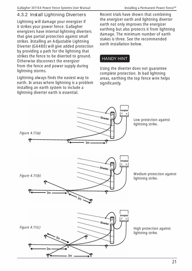
4.3.2 Install Lightning Diverters
Lightning will damage your energizer if it strikes your power fence. Gallagher energizers have internal lightning diverters that give partial protection against small strikes. Installing an Adjustable Lightning Diverter (G6480) will give added protection by providing a path for the lightning that strikes the fence to be diverted to ground. Otherwise disconnect the energizer from the fence and power supply during lightning storms.
Lightning always finds the easiest way to earth. In areas where lightning is a problem installing an earth system to include a lightning diverter earth is essential.
Recent trials have shown that combining the energizer earth and lightning diverter earth not only improves the energizer earthing but also protects it from lightning damage. The minimum number of earth stakes is three. See the recommended earth installation below.
Using the diverter does not guarantee complete protection. In bad lightning areas, earthing the top fence wire helps significantly.
Low protection against lightning strike.
Medium protection against lightning strike.
High protection against lightning strike.
Figure 4.11(a)
Figure 4.11(b)
Figure 4.11(c)
HANDY HINT

22
Gallagher 3E1164 Power Fence Systems User ManualInstalling a Permanent Power FenceTM
Resistance
It is important to understand how the resistance of different leadout wires can affect the performance of your electric fence.Resistance (Ohms) measures a wire’s ability to conduct electricity (current). The lower the Ohms, the more current it will conduct. It has the same effect as the friction of a water pipe has on water flow. Voltage in electricity is like pressure in water. Electric current (amps) is like water volume or flow.
4.4 Fence Construction4.4.1 Install the leadout
The leadout cable is the power link between the Energizer and the fence. The leadout cable can be either run overhead or underground.
Insulated leadout cable should be used to prevent the leadout from shorting out on obstructions or the ground.
������ �
����������
������ ��
���������
�������� ��������� �������������������������������
���� ��
�������������������������������������������������������
�������!����"��#��$� ���
������� �
�����������
����� ��
���������
%��&����� ������������������������������
���� ��
%��&����������������������������������������������������
%��&����!����"����$� ���
%��&���� �
%��&��������
����� ��
��������
%��&����� ��������� ��������������������' ����������������
������ ���
%��&�������������� ��������������������������' ������������������
%��&����!����"����$� ���
Figure 4.12(a)
Figure 4.12(b)
Figure 4.12(c)
23
Gallagher 3E1164 Power Fence Systems User Manual Installing a Permanent Power FenceTM
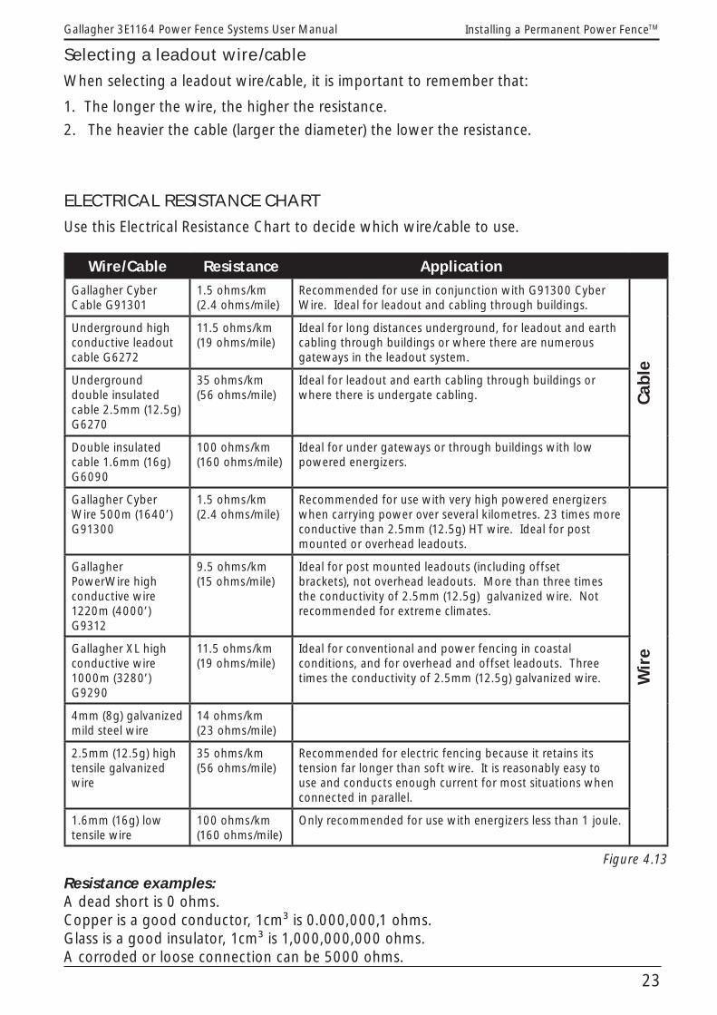
ELECTRICAL RESISTANCE CHART
Use this Electrical Resistance Chart to decide which wire/cable to use.
Wire/Cable Resistance ApplicationGallagher Cyber Cable G91301
1.5 ohms/km (2.4 ohms/mile)
Recommended for use in conjunction with G91300 Cyber Wire. Ideal for leadout and cabling through buildings.
Cabl
e
Underground high conductive leadout cable G6272
11.5 ohms/km (19 ohms/mile)
Ideal for long distances underground, for leadout and earth cabling through buildings or where there are numerous gateways in the leadout system.
Underground double insulated cable 2.5mm (12.5g) G6270
35 ohms/km (56 ohms/mile)
Ideal for leadout and earth cabling through buildings or where there is undergate cabling.
Double insulated cable 1.6mm (16g) G6090
100 ohms/km (160 ohms/mile)
Ideal for under gateways or through buildings with low powered energizers.
Gallagher Cyber Wire 500m (1640’) G91300
1.5 ohms/km (2.4 ohms/mile)
Recommended for use with very high powered energizers when carrying power over several kilometres. 23 times more conductive than 2.5mm (12.5g) HT wire. Ideal for post mounted or overhead leadouts.
Wir
e
Gallagher PowerWire high conductive wire 1220m (4000’) G9312
9.5 ohms/km (15 ohms/mile)
Ideal for post mounted leadouts (including offset brackets), not overhead leadouts. More than three times the conductivity of 2.5mm (12.5g) galvanized wire. Not recommended for extreme climates.
Gallagher XL high conductive wire 1000m (3280’) G9290
11.5 ohms/km (19 ohms/mile)
Ideal for conventional and power fencing in coastal conditions, and for overhead and offset leadouts. Three times the conductivity of 2.5mm (12.5g) galvanized wire.
4mm (8g) galvanized mild steel wire
14 ohms/km (23 ohms/mile)
2.5mm (12.5g) high tensile galvanized wire
35 ohms/km (56 ohms/mile)
Recommended for electric fencing because it retains its tension far longer than soft wire. It is reasonably easy to use and conducts enough current for most situations when connected in parallel.
1.6mm (16g) low tensile wire
100 ohms/km (160 ohms/mile)
Only recommended for use with energizers less than 1 joule.
Figure 4.13
Resistance examples:A dead short is 0 ohms.Copper is a good conductor, 1cm³ is 0.000,000,1 ohms.Glass is a good insulator, 1cm³ is 1,000,000,000 ohms.A corroded or loose connection can be 5000 ohms.
Selecting a leadout wire/cable
When selecting a leadout wire/cable, it is important to remember that:
1. The longer the wire, the higher the resistance.
2. The heavier the cable (larger the diameter) the lower the resistance.

24
Gallagher 3E1164 Power Fence Systems User ManualInstalling a Permanent Power FenceTM
Maintain good conductivity throughout the fencing system by always using the correct wire or cable. High powered energizers require large capacity wire or cable. Small diameter cable will restrict current flow with subsequent voltage loss on the fence.
NEVER use household electrical cable. It is made for low voltage use only.
NEVER use copper wire/cable because electrolysis (electrical corrosion) occurs where it joins galvanised wire.
Electrifying remote areas
Where the electric fence system is several kilometres (miles) from the mains power supply there are several ways to feed the power out to the fence.
A Use a mains powered energizer and transmit the power from the energizer to the fence through leadout wire(s).
B Use a battery powered energizer with solar panel charging - the battery is kept charged by the solar panel installed at the remote location.
C Use a battery powered energizer - recharge the battery as necessary or alternate 2 batteries.
If choosing A, the options in order of priority are:
1 1 x Cyber Wire (G91300) (1.5 ohms/km, 2.4 ohms/mile)
2 A well constructed 4 or 5 wire electric fence with 2.5mm (12.5g) wires connected in parallel at both ends. It can also be used to form a laneway (7 ohms/km, 11 ohms/mile)
3 1 x Aluminium Power Fence wire (G9312) (9.5 ohms/km, 15 ohms/mile)
4 1 x Aluminium coated steel wire (G9290) (11.5 ohms/km, 18 ohms/mile)
5 1 x 4mm (8g) wire (14 ohms/km, 23 ohms/mile)
6 2 x 2.5mm (12.5g) wires (17.5 ohms/km, 28 ohms/mile)
7 1 x 2.5mm (12.5 gauge) wire (35 ohms/km, 56 ohms/mile)
If using a multi-wire fence, divide the resistance value of each wire by the number of wires e.g. for a 4-wire 2.5mm (12.5 gauge) fence: 35/4 = approximately 9 ohms/km.
Multiples of the above wires may be needed depending on the distance from the energizer to the fence and the amount of fence to be powered. The wires can be supported on a non-electric fence using offset brackets or post insulators.
Another option is to insulate and electrify one or more wires in a non-electric fence, providing it/they are not barbed or part of a fence that has any barbed wires.
HANDY HINT

25
Gallagher 3E1164 Power Fence Systems User Manual Installing a Permanent Power FenceTM
4.4.2 Building the fence
Install end strain and corner posts
Plan the fence line. Avoid rough, stony or steep areas if possible. For best electric fence performance use multi-wire (at least 3 wires connected in parallel) fencing.
Next set the end strainer posts in position. A 2.1m (7ft) post, 150mm (6”) in diameter is usually strong enough. (If you are planning to hang a heavy gate from the post, ensure the post is strong enough.)
Use a bedlog, angle stay or H brace stay assembly, whichever suits your ground conditions and fence type.
BedlogA bedlog is best suited for up to 4 wire fences, in firm ground, with low/medium tension fences.
Angle stayUse an angle stay for 5 wire fences, in firm ground, with medium tension fences.If you use an angle stay (See Figure 4.15) make sure it is at least 2.1m (7ft) long. The stay hole in the strainer post should be just less than halfway up the post from ground level. This will give the correct angle to the stay. Dig a suitable stay-block into firm ground, at least 100mm (4”) below the surface. The position of the stay-block should ensure that the stay fits tightly into the hole in the strainer post and is in line with the fence. On the back of the post, attach a foot block to prevent the post rotating up and out of the ground.
())���*��+,
�)����*-+,
.�����*�(+,
(�����*/+,
�)����*-+,
�)����*-+,
CAUTION: Bedlogs should not be used in soft or swampy ground.
1.2m (4ft) stay block or half post
Foot block
Angle stay
G607G603
G605
Figure 4.15
H brace assemblyAn H brace assembly (horizontal stay) (see Figure 4.16) is best suited to soft ground and will also withstand high strains. In addition to the strainer post install an additional post approximately 2m (6ft) away from the strainer post and in line with the fence wires. Notch a horizontal post into the top of each vertical post and hold it in place with a tension wire. Strained using a G643 wire tightner.
Figure 4.16
All Live
.�����*�(+,
()����*��+,
�)����*-+,
(�����*/+,
.�����*�(+,
G627 or G609 in plastic piping
1.2m (4ft) long bedlog or half post
G607G603
G605
Figure 4.14(a)
Earth Wire Return
.�����*�(+,
()����*��+,
�)����*-+,
(�����*/+,
.�����*�(+, 1.2m (4ft) long bedlog or half post
G607 G603
G627 or G609 in plastic piping
Figure 4.14(b)
G627 or G609in plastic piping
300mm (12”)
G603
G673
G643
G605
Tension wire

26
Gallagher 3E1164 Power Fence Systems User ManualInstalling a Permanent Power FenceTM
Install the strain insulators
Mark the wire spacings on the strainer posts. Tie the insulators no more than 100mm (4”) away from the post to prevent animals pushing through the fence between the post and insulators.
A Start with a 900mm (3ft) length of wire.
Figure 4.17(a)B Form a knot as shown and slide it
firmly to the middle of the post.
Figure 4.17(b)C Finish with a tight tie-off. Wrap the
wire 3 times around the strain wire. Cut or break off the remaining wire.
Figure 4.17(c) D Wind the wire once around the
insulator. Bend the wire as shown (see Figure 4.19) so the strain is from the centre of the insulator.
Figure 4.17(d)
E Wrap the wire six times from this bend.
Figure 4.17(e)F Tie off tightly and cut or break off the
remaining tail.
Figure 4.17(f)
Choosing insulators:
We build our insulators from the highest quality raw material to last a lifetime. The porcelain insulators are fire-resistant and ideal for high fire-risk areas. The plastic insulators are made from UV stabilised polymers for sun resistance, toughness and durability. All Gallagher insulators feature long leakage paths and protective shields to achieve optimum performance from today’s high power energizers (except the G6840 and G6830 Nail on insulators).
HANDY HINT
It is important that the pull (or strain) is from the centre of the strain insulator.
Figure 4.18
G677 orG678
INSULATOR FACTS

27
Gallagher 3E1164 Power Fence Systems User Manual Installing a Permanent Power FenceTM
To save time and effort, purchase a Gallagher Termination Kit (G618). This kit includes pre-assembled insulated wire strainers and wire loops for your end posts, eliminating the need for special tools or wire tying.
Install angle posts
If you need to install angle posts a breastblock is usually sufficient support for an angle post. If the angle is not too great use in-line insulators (eg. W insulator G6730) on the outside of the post.
Figure 4.19(a)On sharper corners you may have to fasten the live wire on the inside of the post to stop it touching the post.
Figure 4.19(b)
Position the line posts and wires
Use a wire dispenser to run out the top and bottom wires as guides for positioning line posts and tie-downs. Use 2.5mm (12.5g) high tensile wire for electric fencing because it retains its tension far longer than soft wire. It is reasonably easy to use and conducts enough current for most situations when connected in parallel.
Attach the top and bottom wires to end strain insulators and any angle or corner insulators. Leave the tails long enough so they can be used for electrical connections later.
Use a Permanent Wire Tightener G6430 (with the Wire Tightener Handle (G6440) or Rapid Wire Tightening Tool (G6450) (see Figures 4.22) to tension the wires just enough to provide a guide to the wire height and provide a straight line for positioning the line posts.
Use softwood, steel or Fibreglass posts on rises. Use droppers with tie-downs in hollows. As each post and tie-down is installed, attach the wires to them to help decide the position of the next post in the fence line. On sharp rises, timber and fibreglass posts may need anti-sink blocks or discs to prevent sinking. Fibreglass posts should only be used in straight lines.
Figure 4.18(a)
HANDY HINT
G618

28
Gallagher 3E1164 Power Fence Systems User ManualInstalling a Permanent Power FenceTM
Tie-downs are anchors to hold the wire down in hollows. For timber droppers, use the Screw in Tie Down (G6150) and the Screw in Tie Down Handle (G6151) to hold the dropper down, see Figure 4.20.
Install the remaining line posts where necessary. On flat or level ground use one post up to every 20-30m (100 ft) and three fibreglass droppers in between. On hilly or uneven ground posts and droppers will need to be closer together to maintain the wire height.
Run out the remaining wires, tie them off to the strain insulators and attach them to all the posts and tie-downs.
For untrained sheep, goats and similar animals the bottom wire should be approx. 150mm (6”) above the ground to prevent them getting under the fence.
HANDY HINT
The Fibreglass Quick Clip (G8350) allows free movement of the wire when straining, see Figure 4.21.
Choosing posts and droppers
There are a number of options for posts and droppers: wood posts, fibreglass or steel posts.
Soft wood round, half round or quarter round posts provide the basis for a strong permanent power fence. Gallagher offers a range of insulators for attaching electric fence wires to the posts. Our G673 W claw insulator provides a strong permanent attachment system with large shield and long leakage paths. Alternatively the G687 pin lock insulator and G690 powerlock products enable the wire to be temporarily removed from the fence for rapid change in paddock configuration, drain cleaning, track grading etc. Insulators are also available for specialist equine fencing products including G669 for 40 mm tape and G676 for equifence. Insulators can be attached to the post using staples, screws or flat head nails.
Posts can be installed by digging a hole and then manually backfilling and ramming the post tight, or by ramming the post into the ground using a tractor- or trailer-mounted post ramming machine (preferable). Post spacing depends on number of wires, wire type, and terrain, and can vary between 4 meters (multi-wire undulating ground) and 15 meters (2 high tensile wires across flat ground). Post spacing can be extended if fibreglass or wooden droppers are installed between the posts.
Steel posts provide a simple alternative to soft wood posts. Steel posts have the advantage of being able to be installed using a sledge hammer or manual post driver, reducing the need for expensive post hole borers or tractor mounted rammers. They can also be driven into hard ground more easily, having a thin plan area.
Gallagher manufactures quality double pinlock insulators (G686) for attaching electric wires to steel “Y” posts, as well
Figure 4.20
G6150
HANDY HINT
HANDY HINT

29
Gallagher 3E1164 Power Fence Systems User Manual Installing a Permanent Power FenceTM
as a topper cap (G685) for securing a top mounted tape or wire. A range of quality insulator products are also available for North American “T” posts. Post spacing is the same as for soft wood posts.
Fibreglass posts are quick and easy to use for permanent and portable fences.
Posts are simply driven into the ground using a hammer and Driver Cap (G8470). Attach wires to the posts using Quick Clips, see Figure 4.21, (G8300 for 10mm (3/8”) post, G8350 for 13mm (1/2”) post). The Pressure Plate (G8400) for 10 and 13mm (3/8” and 1/2”) posts can be secured to a tie down or used as anti sink pads.
Approx. fencing requirements per km (5/8 mile):
Flat land: 50 x 13mm (1/2”) posts 150 x 10mm (3/8”) droppers.
Uneven land 70 x 13mm (1/2”) posts210 x 10mm (3/8”) droppers.
These amounts may vary depending on ground contour.
Figure 4.21
Tension the wires
Tension the wires to approx. 90kg (200lb) using Permanent Wire Tighteners (Figure 4.22(a) - G643) and a suitable tensioning
handle (Figure 4.22(c) - G645). If wild animal pressure is likely, increase the tension, especially on the bottom wires. In countries where snow load is a problem or where wild life may come into heavy contact with the fence, install Permanent Tension Springs (G6250) to help prevent the wire overstretching.
Place the Permanent Wire Tighteners (G6430, see Figure 4.22a) in the centre of the fence so the wire pulls in from both ends.
Figure 4.22(a)
Figure 4.22(b)
Figure 4.22(c)
Wire storage and handling
Store coils of wire in a dry area and away from fertilisers, lime, acids and other chemicals. Avoid dropping wire onto stony or abrasive surfaces that can damage the galvanising. Take care not to bend any wires in the coil as this makes it difficult to unwind.
G8100 / G8201
G8300 / G8350
G643
G644
G645
HANDY HINT

30
Gallagher 3E1164 Power Fence Systems User ManualInstalling a Permanent Power FenceTM
Join wire using a figure eight or reef knot. These will give better electrical contact than a double loop join.
Figure 4.23(a)
All other permanent connections should be clamped using Joint Clamps (G603), see Figures 4.23a and 4.23b, to ensure tight wire connections.
Figure 4.23(b)
Figure 4.23(c)
Electrical connections
Connect all live wires in parallel at both ends of the fence. This will ensure maximum conductivity. For a three wire fence, bring the tails, previously left long (refer to section “Position the line posts and wires” under section 4.4.2 Building the fence) from the top and third wires to the second wire and connect firmly with a Joint Clamp (G6030 or G6035), see Figure 4.23. Make sure it’s tight. Wrap the excess wire around this second wire and break it off for a smooth, tidy finish. Bring the tail from the second fence wire to a Gallagher Cut Out Switch (G6076 and G6087), see Figure 4.29 where necessary, otherwise break it off. This wiring configuration minimises the number of joint clamps required and creates a tidy installation.
Figure 4.24
Attaching a Flexible Connector (G6050) to the lower wires means you can easily disconnect them at times when there is high vegetation growth. Make a loop on the tail of each wire, adjacent to the wire above it, and attach the Flexible Connector. Connect it to a powered wire as shown.
Figure 4.25
G6033
G6035
Step 1
Step 2
Figure of eight knot
Reef knot
G607G603
HANDY HINT
HANDY HINT

31
Gallagher 3E1164 Power Fence Systems User Manual Installing a Permanent Power FenceTM
Gates and gateways
Where possible, position gateways on flat, firm areas, away from steep banks (where erosion could occur). Carry the power (and earth return if you have an earth wire return system) across the gateways, preferably underground, using double insulated cable (G6270, G6272). Bury the cable at least 300mm (12”) deep and cover with soil free from stones. Connect the cable ends to the fence using Joint Clamps (G6030 or G6035), see Figure 4.23,or through a Cut Out Switch (G6076 and G6087), see Figure 4.29.
Figure 4.26
For extra protection lay cable in plastic pipe. Lay the pipe with the ends bent down to keep out water (see Figure 4.27).
Figure 4.27
Electrifi ed gates
Choose from high visibility electrified spring gates, tape gates or bungy gates.
Tape gates provide the most visible gate solution. Choose spring or bungy gates where the gate needs to be stretched across a lane to divert animals into the paddock.
WARNING: Do not rely on electric gates to get power across gateways because when the gates are open power is lost to the fence.
Figure 4.28(a) - Spring
Figure 4.28(b) - Tape
Figure 4.28(c) - Bungy
G6401
G6410
G6405
300mm
HANDY HINT

32
Gallagher 3E1164 Power Fence Systems User ManualInstalling a Permanent Power FenceTM
Install cut out switches
Cut out switches, see Figure 4.29, (G6076 and G6087) are handy for isolating different sections of the fence. This is useful when you are looking for faults or carrying out maintenance. Place cut out switches at gateways or junctions where either single or multiple fence lines can be turned off (see Figure 4.1).Connect the undergate cable to one switch terminal and the tail of the second line wire to the other terminal.
Figure 4.29
4.4.3 Fence protection
Old non-electric fences can be made to last for many more years by attaching offset brackets with an electrified wire on one or both sides of the fence.
Attach single offset wires at two thirds the height of the animal to be controlled. If sheep and cattle are in the same area it is better to use two offset wires (one for sheep, one for cows). However a single wire three quarters the height of the sheep will still protect the fence from both animal types.
If the old fence is tangled or has broken wires, it will need to be tidied up. Otherwise you will run the risk of loose wires causing accidental shorting on the offset wire. Remove the worst wires and tighten the others where possible.
On level ground, offset brackets should be spaced approximately 20m (66ft) apart.
Over uneven ground, space the offsets closer to maintain a constant wire height above the ground. Attach them next to posts for extra stability.
Choosing offset brackets
Wire offsets
Made from galvanised high tensile spring wire, these offsets twist onto existing fence wires.
Figure 4.30Wooden post offsets
Made from galvanised high tensile spring wire this offset is stapled to wooden posts.
G6620
Figure 4.31
0-(1�
To energizer
To fence
Cut out switch
HANDY HINT

33
Gallagher 3E1164 Power Fence Systems User Manual Installing a Permanent Power FenceTM
G6601 / G6602
Pigtail offsets
These are driven into softwood posts then stapled in place (for hard timbers pre-drill a pilot hole).
Figure 4.32Fibreglass offsets
These are driven into softwood posts using a Driver cap G8470 on the end to prevent splintering (for hard timbers pre-drill a pilot hole).
Figure 4.33Chain link offsets
Made from galvanised high tensile spring wire, this offset twists onto existing chain link wires.
Figure 4.34
4.4.4 Stock control during power failures
Animals which have grown up with electric fencing avoid the fence but may eventually touch the wires accidentally and know when the power is off. Those with less training or where there is a strong temptation to escape may get through the fence.
A
B
C
DE
F
A Double Insulated CableB Permanent Wire TightenerC 150mm (6”) for sheep / 300mm (12”) for cattleD Maximum high water levelE 3.5mm (9 guage) chainF 150mm (6”) above average water level
G6040
Where long power failures are likely, keep a battery powered energizer as an emergency unit or use a combination battery/mains unit, such as one from the Gallagher SmartPower MBX energizer range.
4.4.5 Electrifi ed fl ood gates
Install an electrified flood gate to prevent animals walking under an electric fence that crosses a water course.
An electric fence that is partly or entirely submerged in water caused by occasional flooding may lose most of its power. To overcome this problem install the Flood Gate Controller (G6040), see Figure 4.35, between the fence and floodgate, via a Cut Out Switch as shown, 150mm (6”) above average water level. This reduces power loss through the flood gate.
Figure 4.35
G6076

34
Gallagher 3E1164 Power Fence Systems User ManualInstalling a Portable Power FenceTM
�
� � � �
�
�
5. INSTALLING A PORTABLE POWER FENCETM Here are the basics for a portable fence:
(A) Reel(B) Polytapes, wire or braids(C) Treadin Post(D) Insul-grips(E) Pigtail Post(F) Energizer(G) Earth Stake(H) Fence Lead(I) Earth Lead
With a portable system you can construct an effective barrier wherever you like for short term stock control. Power it with any of the Gallagher battery powered energizers or connect it to a mains powered electric fence.
Portable fences are suitable for all types and sizes of animals by using one of the many options available.
5.1 Planning the fence layout
Figure 5.1

35
Gallagher 3E1164 Power Fence Systems User Manual Installing a Portable Power FenceTM
5.2 Selecting the correct EnergizerUse the following chart to select the correct energizer for your fence.
Portable Energizer Selection Chart - by Fence Distance (km)
Energizer Stored Energy(Joules)
Maximum Distance of Fence - (km)
Gallagher Recommendations (multi-wire fence)
Animals Controlled
High Vegetation
Average Vegetation
No / Low Vegetation
PowerPlus B1600 16 8 15 60
PowerPlus B700 7 5 10 40
PowerPlus B280 2.8 2 8 35
PowerPlus B180 1.7 1 6 25
PowerPlus B80 0.8 0.75 4 12
PowerPlus B40 0.38 0.5 1.5 6
B11 0.11 • • 1
PowerBox B300 2.6 2 6 30
PowerBox B200 1.45 1 4 20
PowerBox B100 0.8 0.75 2.5 12
PowerPlus Solar S50 0.5 1.2 2.0 8.0
PowerPlus Solar S20 0.2 • 1.2 3.0
Solar S17 0.15 • 1.0 1.5
Figure 5.2

36
Gallagher 3E1164 Power Fence Systems User ManualInstalling a Portable Power FenceTM
Portable energizers are generally operated by either “D” cell batteries, a 9 volt disposable dry cell battery,or a 12 volt rechargeable battery.Strip grazers, like the B11, are designed for single reel systems and can be operated by 6 “D” size batteries or a 12 volt rechargeable battery. The B11 is a cost effective strip grazing product for relatively short lengths of fence (500 m).
Gallagher 9 Volt energizers, such as the B40, have a higher power output and are suitable for significantly longer fence length. The unit can be operated from either 12 V or special purpose Gallagher 9 volt air depolarising batteries. The 9V option provides extremely long life and is an environmentally friendly design, for extra convenience during the break feeding season.
For multiwire sheep fencing, the more powerful B100 - B300 PowerBox range uses deep cycle batteries. Solar charging options are available for this range.
The portable solar S17 energizer, supplied complete with integrated battery and solar panel, provides a maintenance-free solar power operation and is ideal for strip grazing. The larger S50 is able to power significantly greater fence length.
Batteries need to be recharged as necessary depending on the size of the energizer, battery capacity and amount of use.
Choosing tape, wire, braid and rope
Tape is generally used where visibility is important. With our Turbo Plus range we’ve drawn on our knowledge of animal psychology by replicating nature’s warning sign: Stripes. Proven to be more effective in deterring stock. Note: Tape is not recommended in areas exposed to very strong wind.
Polywire/Turbo Wire is preferable where wind or adverse weather conditions would “work” a tape to deterioration and enables maximum length of fence to be carried on a reel.
Braid is a woven product designed not to “tangle” or overstretch. It is not available in all countries.
Portable Fencing Wire Product Performance
There are three criteria for determining performance.
- Conductivity (resistance): how much power the products delivers and how far.
- Durability: how the product stands up to wear and tear under varying environmental conditions.
- Design: how the product performs long term – eg. if a strand is broken, is it powered further along the fence?
Copper wire used in some fence products is highly conductive but it is not as strong as stainless steel and can “fatigue”, deteriorate and break easily. Stainless steel wire is stronger but is less conductive. The best option, Turbo, developed by Gallagher, is mixed metal strands that offer power, performance and durability – the best of both worlds. In the Gallagher range, Turbo products are better for longer term reliability and conductivity. They are less likely to be challenged, damaged or broken by stock.

37
Gallagher 3E1164 Power Fence Systems User Manual Installing a Portable Power FenceTM
Electrical Resistance ChartUse this Electrical Resistance Chart to decide which wire to use.
Product G No. Ohms per km (mile) Suggested Max. single
wire distance
Standard PolyTape 12.5mm (½”)
G6231 G6230
Resistance: 8500 Ohms/km (13600 Ohms/mile)
200m (656 ft)
PolyStandard PolyTape
40mm (1½”)G6240 Resistance: 2400 Ohms/km (3800 Ohms/mile) 350m
(1155 ft)
Standard Polywire G6200 G6201
Resistance: 6000 Ohms/km (10000 Ohms/mile)
200m (656 ft)
Turbo Tape 12.5mm (½”)
G62354 G62356
Resistance: 250 Ohms/km (400 Ohms/mile) - 30 times more conductive than standard PolyTape
3300m (2 miles)
Turb
oTurbo Wire G6205 Resistance: 130 Ohms/km (210 Ohms/mile) - 40 times more conductive than standard Polywire
6400m (4 miles)
Turbo Rope G6225 Resistance: 130 Ohms/km (210 Ohms/mile) - 40 times more conductive than standard Polyrope
6400m (4 miles)
Turbo Plus Tape 12.5mm (½”)
G62364 G62366
Resistance: 150 Ohms/km (240 Ohms/mile) - 60 times more conductive than standard PolyTape
5500m (3.4 miles)
Turb
oPlu
sTurbo Plus Tape 40mm (1½”)
G62483 G62484
Resistance: 140 Ohms/km (225 Ohms/mile) - 20 times more conductive than standard PolyTape
6000m (3.7 miles)
Turbo Plus Braid 12.5mm (½”)
G62184 G62186
Resistance: 96 Ohms/km (155 Ohms/mile) - 60 times more conductive than standard Polybraid
8700m (5.4 miles)
Turbo Plus Super Braid G62164 Resistance: 96 Ohms/km (155 Ohms/mile) - 60 times more conductive than standard Polybraid
8700m (5.4 miles)
Specifications may vary in some countries and are subject to change. Figure 5.3
Tumblewheels
Figure 5.4
Where several blocks are needed in one paddock or if the ground is too hard for Treadins, Tumblewheels (G6380), see FIgure 5.4, are ideal. The Tumblewheels are spaced across the paddock and held upright with the tension of the single line fence passing through their centre. When one or both ends of the fence is moved, the wheels roll along.
A patented switch in the hub ensures all the legs are continuously electrified except for the two on the ground. This prevents animals from moving the fence.
G6380

38
Gallagher 3E1164 Power Fence Systems User ManualInstalling a Portable Power FenceTM
5.3 Fence ConstructionReels holding Polywire/Polytape can be used individually for single line fences or for up to four lines using four reels attached to a reel stand.
1. Single wire: To erect a single line cattle fence, hook the Insul-grip to the anchor point. Carrying the reel and sufficient standards (Treadin (G636) or Pigtail (G642), walk along the proposed line, allowing the reel to unwind.
Place a Treadin standard every 20m (66ft) or closer on uneven ground and locate the Polywire/Polytape in the required Treadin lug. At the end of the fence, hook the reel on to the anchor fence, engage the ratchet and tension the wire. Use a battery powered energizer or connect it to an adjacent mains electric fence wire with a Single Reel Lead Connector (G6340).
When you remove the fence, do the same process in reverse. Do NOT wind the Polywire through the Treadin lugs as this will damage the lug as the wire is abrasive.
2. Multi-wire: To erect a multi-wire sheep or goat fence, attach the required reels to a reel stand. Chain the reel stand to an anchor point. Attach Insul-grips to the ends of the Polywire/Polytape and hook them through the appropriate lugs of one Treadin to prevent them becoming twisted. Make sure the reel ratchets are disengaged. Walk to the other end of the proposed fence line with the Treadin posts pulling out all the wires. Hook the Insul-grips to the anchor
fence. Walk back to the reels placing a Treadin every 10-12m (33-40 ft) or as necessary to maintain wire height over uneven ground and locate the wires in the correct lugs. Tension the wires at the reels and connect the power using a Multi Reel Lead Connector (G63450).
HANDY HINT
Joining Polywire and Polytape
It is important to have good conductivity through the connection when you join Polywire or Polytape. To do this, separate the metal strands by melting a strip of plastic threads with a match or lighter approximately 50mm (2”) from the ends of each length. Pull the end off the plastic being careful not to break the steel wires. Tie both ends of the Polywire/Polytape together and then twist the steel wires together. For joining 40mm (1 ½”) Polytape use a Tape Joiner (G6520). These also give good electrical contact.
Figure 5.5

39
Gallagher 3E1164 Power Fence Systems User Manual Fault Finding
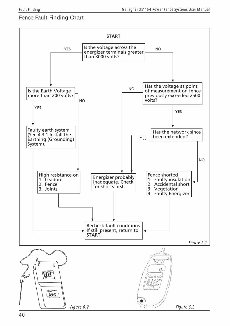
6. FAULT FINDING6.1 Fence tools and testersSmartfix is Gallagher’s voltmeter (see Figure 6.3), current meter and fault finder in one. It saves hours checking fence lines for faults.
Digital Volt Meter DVM3 (see Figure 6.2) – a tool for monitoring fence voltage and helping trace fence line faults.Neon tester – a simple tool for testing whether there is sufficient power on the fence.Livelite – tells you in a flash whether your fence is operating.
6.2 TroubleshootingMonitor the fence voltage using either a Digital Volt Meter (DVM) (G5030) or a Smartfix (G5090) in voltage mode.
If your fence has less than the recommended 3000V (3kV) minimum, check that:
1. The energizer earth is O.K.
2. The energizer is powerful enough.
3. There are no shorts on the fence line.
4. The fence is correctly constructed.
5. Vegetation growth is not causing power loss.
6. The leadout wire is adequate.
To trace a fault using a DVM travel along the fence line and check the voltage about every 100m (330ft). If the short is serious, the voltage will continue to fall until the fault is reached. If the fault is passed the voltage will remain fairly constant. You should then backtrack to find it. At fence junctions isolate different fences with a Cut Out Switch (G6076 and G6087).
To trace a fault using a Smartfix (G5090) place it on the fence with the wire in the measurement slot and making good contact with the contact plate. The
arrow on the LCD display will indicate which direction the current is flowing. The amount of Amps flowing in the wire is indicated by a number on the display screen when the Smartfix is operating in current measurement mode. The higher the number, the bigger the fence fault (short).
Progress as above. If the current reading drops significantly the fault is back towards your previous reading. The process is similar to finding water leaks, where the smartfix is reporting the amount and direction of the flow.
6.3 InductionInduction is the transfer of voltage from a live wire to a neutral wire by electromagnetic rather than direct physical contact.
If you are getting a small shock from “non-live” wires or steel gates, particular in dry weather, this is likely to be caused by induction. Neutral wires (neither live nor earth) can be charged from live wires (usually leadout or offset wires), running parallel. It is not a short and will not reduce fence voltage. To remove the problem, earth / ground out the offending wires by pushing a heavy gauge galvanised wire as far as possible into the ground next to the strain post and staple it across the offending wires. This will not reduce the voltage on the insulated powered wires.
40
Gallagher 3E1164 Power Fence Systems User ManualFault Finding
2� ��3����&��3����*����4#.#��5��������&�!��&����*0� �����,�3����,#
2������&�����# 2� ��3���� ������(# 6�����������&��.# ����������4# 2� ��3�!����"�
Fence Fault Finding Chart
Figure 6.1
Figure 6.2 Figure 6.3

41
Gallagher 3E1164 Power Fence Systems User Manual Stock Control
7.3 Feral (wildlife) FencingElectric fencing is a highly efficient and low cost method of controlling unwanted vermin and wildlife that can result in costly stock deaths or grazing loss. Excellent results can be achieved with either a free-standing fence or one which reinforces existing fences. Most animals will try to go under or through fences. Live earth systems are the preferred design, see Figure 4.7(a).
See your Gallagher dealer for detailed information on feral fencing.
7.4 Equine FencingGallagher understands that unlike many other animals, horses are lively, temperamental and sometimes unpredictable. That’s why we created the Gallagher EquiFence system - a safe, highly visible fence that doesn’t stretch in the wind. Commonly used with steel posts, wooden posts and pigtail offsets on existing fences, Equifence is a versatile, effective solution for permanent horse control.
See your Gallagher dealer for detailed information on the Gallagher EquiFence system.
7. STOCK CONTROL7.1 Training stock to respect Power FencingTM All animals need time and space to discover that electrified fences are “hot”. This education period must be carried out with as little stress as possible.
Choose a small, well fenced holding paddock and put offset wires on the inside of the perimeter fence about two thirds of the height of the animals you are training.
If possible earth the rest of the fence to the energizer earth and electrify the offset wires with the strongest possible pulse for the best results. You may need to disconnect the rest of the farm to achieve this.
Tropical breeds of cattle which sometimes jump fences can be trained not to jump with a high powered shock in a training paddock with an offset wire attached to a high fence.
The minimum time required is 12 hours and most animals will be fully trained and approaching the fences with caution in 48 hours. Persistent jumpers may have to be culled.
7.2 Training dogs to work around Power FencesTM Train a dog to jump over electric fences. Simply use the command “Jump” and “No” if the dog goes to crawl under or jump through. Whenever a dog receives a shock, shout “No” and the same command will be more rapidly obeyed.

42
Gallagher 3E1164 Power Fence Systems User ManualSafety Requirements and Regulations
8.1 Warning signsElectric fences bordering public thoroughfares are required to have a warning sign (G6021) at least every 90m (295ft).
�������� ��������
�������������������������
Figure 8.1Check with your local authority for specifi c regulations.
8.2 Radio interferenceGallagher energizers comply with usual Telecom and International standards and safety regulations. However, problems can arise for a number of reasons and can be difficult to eliminate in areas with poor radio reception.
To avoid radio interference:
• The energizer earth must be highly conductive (refer to “4.3.1 Installing the Earthing (Grounding) System”)
• The energizer must be well away from any mains power supply earth and neither should be connected to water pipes.
• Do not allow an energizer earth wire to touch a building which can act as a broadcast aerial. Use Leadout Cable G627 to insulate the earth wire.
• Earth the offending radio and improve its aerial. Try to keep both as far away from the energizer and fence lines as possible.
• The mains power supply earth must be in good condition.
• The mains power supply plugs and sockets for the energizer and radio must be in good condition with no loose connection.
• Spray grass along fence lines closest to the radio with defoliant spray.
8.3 Telephone interferenceTo avoid telephone interference:
• Do not have electric fence wires running for any distance parallel to telephone wires or power lines. This particularly applies if the electric fence wire is carrying high current, such as a leadout wire to a large fencing system.
• All joins should be “figure eight” or “reef knots” and all other connections should be joint clamped securely so there is no sparking. Re-tighten clamps every summer.
• Ensure cut out switches are in good condition with no loose connections.
• Maintain your insulators in good condition. Poor quality insulators can cause problems that are difficult to trace. Sparking inside these also causes radio interference.
• Under gateways, use Leadout Cable (G6270 or G6272) threaded through plastic piping for physical protection, avoiding sharp objects. It must be flexible to allow for strainer post movement.
• To find leaks, shorts, faulty joins, broken wires, and faulty insulators, walk the fence lines with a transistor radio tuned off the station and on high volume. It will click when a fault is close.
• If there is still a problem:Operate the energizer without the earth or fence connected. If the interference stops then the fault is in the fence line or earth. If it is still there then the fault is in the energizer or in the mains (110V/230V) power supply connections.
8. SAFETY REQUIREMENTS AND REGULATIONS
43
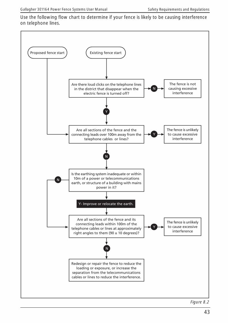
Gallagher 3E1164 Power Fence Systems User Manual Safety Requirements and Regulations
Use the following flow chart to determine if your fence is likely to be causing interference on telephone lines.
!7����������������������������������
6���&����� �������������&�������&�������������&�����������&�������������&����&�
������������������ �������8
6�������������������&�������������&������������������������������3������&�
�����&������'������������8
5���&�����&�����3����������9 ���������&�������������������������� ������������&������ �� �������' ����������&������
����������8
6�������������������&�����������������������������������&������������&�
�����&������'�������������������7������3��&�������������&���*1��:����������,8
;����������������&������������� ����&������������7��� ��������������&�
���������������&���������� �����������'����������������� ����&������������#
<=�5�����������������&�����&#
>&���������������� ������7�����������������
>&����������� ������3����� ����7�����������������
>&����������� ������3����� ����7�����������������
�
<
�
<
�
<
�
Figure 8.2

44
Gallagher 3E1164 Power Fence Systems User ManualSafety Requirements and Regulations
1. Draw a plan of the farm approximately to scale showing all electrified wires. Include the connecting leads from the energizer to the fence and earth electrode, and wires crossing gateways and roads even if they are underground.
2. Find out the location of communication cables and lines on or near the electric fence and draw them on the plan.
3. Draw on the plan a shaded stripe 200m wide centred on each of the
communication cables or lines as shown in Figure 8.3. Electric fence wires within the shaded area are the most likely to cause interference due to their close proximity to the communication cables or lines.
4. Highlight on the plan those fence wires that run parallel to communication cables or lines, and are within 100m of them as shown in Figure 8.3. Those at right angles to cables or lines will not normally cause significant interference and may be ignored.
����
�����������
����������
�������� ���������
����
Figure 8.3

45
Gallagher 3E1164 Power Fence Systems User Manual Safety Requirements and Regulations
An example of a bad electric fence configuration from an interference perspective is presented in Figure 8.4.
This example shows common design mistakes of running feeders adjacent to communication cables or lines, (e.g. down the driveway and both sides of the road), and an earth electrode connecting the lead parallel to communication cables or lines.
Where a feeder is required to cross a communication cable or line, (e.g. to feed paddocks across the road), the crossing should be at right angles to the communication cable or line for 100m on either side of the communication cable or line.
������������������������������������������������������������������������������������������������������������������������������������������������ ��
���
����
����
�������
����������
�!��
���� ���������
Figure 8.4
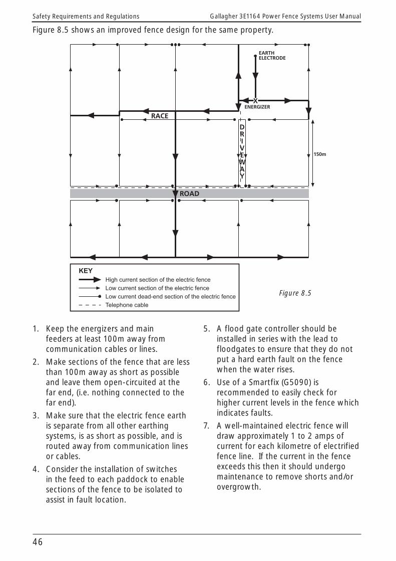
46
Gallagher 3E1164 Power Fence Systems User ManualSafety Requirements and Regulations
Figure 8.5 shows an improved fence design for the same property.
1. Keep the energizers and main feeders at least 100m away from communication cables or lines.
2. Make sections of the fence that are less than 100m away as short as possible and leave them open-circuited at the far end, (i.e. nothing connected to the far end).
3. Make sure that the electric fence earth is separate from all other earthing systems, is as short as possible, and is routed away from communication lines or cables.
4. Consider the installation of switches in the feed to each paddock to enable sections of the fence to be isolated to assist in fault location.
5. A flood gate controller should be installed in series with the lead to floodgates to ensure that they do not put a hard earth fault on the fence when the water rises.
6. Use of a Smartfix (G5090) is recommended to easily check for higher current levels in the fence which indicates faults.
7. A well-maintained electric fence will draw approximately 1 to 2 amps of current for each kilometre of electrified fence line. If the current in the fence exceeds this then it should undergo maintenance to remove shorts and/or overgrowth.
�������
����
����
����������
�!��
���� ���������
������������������������������������������������������������������������������������������������������������������������������������������������ ��
���
Figure 8.5

47
Gallagher 3E1164 Power Fence Systems User Manual Glossary
9. Glossary9.1 Electrical Terms
Electrical Terms
Symbol Definition
a.c. Alternating current as from mains.
Ampere A Value of current flow (amps). The equivalent in water flow is litre/hr.
Circuit A conducting path around which electrons (current) flow.
Current I Flow of electrons, measured in amperes. It is the duration and rate of flow of the current which causes a shock. Increasing the voltage increases the current. Increasing Resistance decreases Current.
d.c. Direct current as from batteries.
Electrolysis Corrosion between different metals in a wet environment such as between copper and galvanised wires on a fence line. Avoid this by only using galvanised wire.
Induction Power transfer without contact. For example, the charging of dead or neutral fence wires which run parallel to live ones. The closer the live and neutral wires and the further they travel together, the greater the amount of inductance.
Joule J Unit of energy. One joule is one watt for one second. It is the measure of “kick” of a pulse. Joules are the most important measure of the power of an energizer.
Leakage Energy caused by poor insulation, shorts and/or vegetation on the wires resulting in a drop in voltage.
Ohm Unit of resistance = volts/amps. The resistance to earth scale is a reverse one, in that a lower value indicates increased shorts to ground. Zero Ohms is a direct short to ground, while very large reistance to ground indicates that the fence is well insulated. 500 Ohms is also the usual energizer test load.
Pulse A brief electrical current or shock emitted by an energizer. Each pulse is on for about 0.0003 of a second. Pulses are spaced about one second apart.
Resistance R Measured in ohms. It is the equivalent of friction in water.
Volt V Unit of electrical pressure which causes current to flow.1000 V equals 1kV Voltage = current x resistance.
Watt W Unit of power, both electrical and mechanical.Volts x Amps = Watts746 Watts = 1 h.p.

48
Gallagher 3E1164 Power Fence Systems User ManualGlossary
9.2 Power Fencing Terms
Power Fencing Jargon
Synonym Definition
All-live electric fencing
All hot An electric fence configuration where all wires are electrified.
Digital Volt Meter DVM, fence voltmeter, tester
A meter for measuring the voltage on an electric fence.
Earthing, earth system
Grounding, ground system An electrical connection to earth/ground, system usually via metal stakes driven into the ground.
Ground rod(s) Ground stake/bar/pegEarth stake/rod/bar/peg
Metal stake driven into the ground. Several stakes connected together form an earth system.
Earth return system Hot/ground return, earth wire fence
An electric fence configuration where both live and earth wires are used, generally in dry conditions. Animals make contact between the live and earth wires.
Earth wire Ground wire A fence wire connected to an earth stake.
Energizer Fencer, charger, controller, power unit, shocker
An electronic “ticking box” for electrifying fences.
Energizer (battery powered)
Battery box An energizer powered from a battery.
Energizer (mains powered)
110V or 230V, Plug-in, hydro
An energizer powered from a mains supply.
Live wire Hot wire, electric wire A fence wire which has been electrified.
Output energy The energy discharged into the fence.
Shorts, shorting Leaks, leakage The energy loss through an undesired path from the live wires to the ground wires.
Stored energy The energy (measured in joules) held within the energizer and discharged with each pulse.