power system module psm installation and operating guide€¦ · installation and operation of the...
TRANSCRIPT

Power System Module PSM DK 7856.019 PSM Measurement Module
Installation and Operating Guide FRIEDHELM L O H GROUP
R i t t a l GmbH & Co. KG Auf dem Stuetzelberg
3 5 7 4 5 H e r b o r n Germany
Email: [email protected] http://www.rittal.de Service Tel. : (+49) - (0)2772 / 505 - 0 Service Fax : (+49) - (0)2772 / 505 - 2319
A39310 00 IT74_eng

PSM Measurement Modul 2
EN We reserve all rights for this technical documentation. Without our previous consent it must neither be reproduced nor made available for third parties. Nor must the receiver or third parties put it to any other misuse. Any violation of the above obliges the violating party to pay compensation and may lead to penal action. Microsoft Windows is a registered trademark of Microsoft Corporation. Acrobat Reader is a registered trademark of Adobe Systems Incorporated.
PSM Measurement module 3
EN Table of Contents
1. Documentation notes ...............................4 1.1. RETENTION OF THE DOCUMENTS................. 4 1.2. USED SYMBOLS.......................................... 4
2. Safety notes .............................................4
3. Introduction ..............................................5
4. Service and service address ....................5
5. PSM Measurement Module ......................6 5.1. SCOPE OF SUPPLY ..................................... 6 5.2. FEATURES ................................................. 6 5.3. OPTIONAL ACCESSORIES ............................ 6 5.4. DESCRIPTION............................................. 7 5.5. CONFIGURATION OF THE METERED PSM .... 8 5.6. CONNECTION TO THE CMC-TC .................. 9
5.6.1. Associated documents..................... 9 5.6.2. Commissioning ................................ 9
6. Maintenance ..........................................10
7. Cleaning.................................................10
8. Disposal .................................................10
9. Accessories for PSM system..................10
10. Technical Specifications.........................11
11. Assembly instructions.............................12 11.1. MOUNTING THE MEASUREMENT MODULE ... 13
11.1.1. Mounting on the PSM bus bar ....... 13 11.1.2. Mounting on a mounting plate ....... 14 11.1.3. Mounting in the enclosure ............. 15
11.2. INFEED STRAIN RELIEF (SUGGESTION) ....... 15 11.3. ALTERNATIVE POSSIBILITIES FOR MOUNTING OF THE CABLE CLAMP BRACKET............................. 16
12. Electrical connection of the bus bar........17 12.1. TECHNICAL DATA OF THE INFEEDS............. 17 12.2. EARTHING ............................................... 18 12.3. INFEED CONNECTION PLUG, DATA AND ASSIGNMENT........................................................ 19 12.4. TERMINAL ASSIGNMENT............................ 19

Documentation notes
PSM Measurement Modul 4
EN
1. Documentation notes The audience for this guide is the technical specialists familiar with the assembly, installation and operation of the Rittal PSM.
• You should read this operating guide prior
to commissioning and store the guide so it is readily accessible for subsequent use.
Rittal cannot accept any liability for damage and operational malfunctions that result from the non-observance of this guide.
1.1. Retention of the documents
This guide and all associated documents are part of the product. They must be given to the operator of the unit and must be stored so they are available when needed.
1.2. Used symbols
The following safety and other notes are used in this guide: Symbol for a handling instruction:
• This bullet point indicates that you should perform an action.
Safety and other notes:
Danger!
Immediate danger to life and limb!
Warning!
Possible danger for the product and the environment!
Note!
Useful information and special features.
2. Safety notes Observe the subsequent general safety notes for the installation and commissioning of the unit:
- Only a trained electrician, in particular for wiring the enclosures with mains power, may perform assembly and installation of the Rittal PSM. Other tasks associated with the Rittal PSM, such as the assembly and installation of system components with tested standard connectors, and only instructed personnel may perform the operation and configuration of the Rittal PSM.
- Observe the valid regulations for the electrical installation for the country in which the unit is installed and operated, and the national regulations for accident prevention. Also observe any company-internal regulations (work, operating and safety regulations).
- Prior to working at the Rittal PSM system, it must be disconnected from the power supply and protected against being switched on again.
- An electrical test must be performed after the completion of the assembly, installation and maintenance work! All protective conductor terminals and the voltages at all connection plugs, and at each individual module slot must be checked.
- Use only genuine or recommended parts and accessories. The use of other parts can void the liability for any resulting consequences.
- Do not make any changes to the Rittal PSM that are not described in this guide or in the associated guides.
- The operational safety of the unit is guaranteed only for its approved use. The limit values stated in the technical specifications may not be exceeded under any circumstances. In particular, this applies to the permitted ambient temperature range and to the permitted IP protection category. When used with a higher required IP protection category, the Rittal PSM must be installed in a housing or
Introduction
PSM Measurement module 5
EN enclosure with a higher IP protection category.
- Operation of the Rittal PSM system in direct contact with water, aggressive media, or inflammable gases and fumes is prohibited.
- In addition to these general safety notes, also observe any special safety notes listed for the specific tasks in the individual sections.
- The strain relief for the connection cable must be made in the immediate vicinity of the connection plug of the PSM bus bar. If the strain relief bracket cannot be attached to the base frame, a suitable punched section must be installed for the mounting of the strain relief bracket.
3. Introduction The stable flow of information and production is the 'lifeline' of an enterprise. Loss of data, failure of function and production causes extensive and in many cases life-threatening damage. Therefore, it is the declared company objective to ensure a maximum of safety and reliability. Rittal offers support to achieve this: By means of universal competence in effective prevention, comprehensive safety, and centralised organisation, i.e. teamwork for IT safety and reliability! This result is an optimum combination of power management and administration, enclosure monitoring, server administration and climate control components.
The solution for the power management is the Rittal PSM – Power System Module. This concept includes complete power distribution of the enclosure, i.e. power supply, distribution and protection.
The PSM offers a revolutionary energy management for IT racks. The modular power supply system permits the power supply using a vertical bus bar on which the power system modules are simply clipped.
The system is made complete by its sophisticated modular structure. A basic installation can be implemented in next to no
time. When demands then grow over time, the original system can simply be expanded with further plug-in modules, also available in various country-specific versions. Rittal does not accept any warranty for any other uses of PSM buses.
4. Service and service address If you have any questions concerning technical or other issues related to our product range, Rittal will be pleased to provide any required support.
You may contact us at the address indicated below. RITTAL GmbH & Co. KG Auf dem Stuetzelberg D-35745 Herborn Germany Email: [email protected]
Note!
Please indicate always the item number in the reference line.
Support Tel.: +49 (0) 2772/505-9052 Complaints: +49 (0) 2772/505-1855 Fax +49 (0) 2772/505-2319 Further information concerning the Rittal PSM can be downloaded from the RimatriX5 homepage www.rimatrix5.com
PSM Measurement Module
PSM Measurement Modul 6
EN
5. PSM Measurement Module Model No.: DK 7856.019
Tested and certified in accordance with DIN EN 60950-1 (VDE 0805):2003-03
Danger!
An electrical test must be performed after the completion of the assembly, installation and maintenance work! All protective conductor terminals and the voltages at all connection plugs, and at each individual module slot must be checked.
Warning!
To prevent damage to the Rittal Metered PSM, ensure that "N" and "L" for the infeed are not interchanged.
Note!
A power pack is required if the Metered PSM is not connected to the CMC-TC Processing Unit. Model number for the required power pack: DK7201.210, a connection cable is also required.
5.1. Scope of supply
1 x PSM Measurement Module 1 x Operating instructions 1 x Cable bracket, incl. assembly parts
5.2. Features
The Rittal PSM Measurement Module offers the option of retrofitting existing PSM bus bars with a measurement function.
It can be used with the following PSM bus bars:
DK 7856.010, DK 7856.020, DK 7856.050, DK 7856.060
After the installation of the measurement module, the bus bar has the same features, as the metered PSM bus bar, DK 7856.016.
The principal features of the Rittal PSM Measurement Module are:
- Compatibility to all Rittal Enclosures and most PSM bus bars.
- Connection to the CMC-TC
- Measurement and display on the current, voltage, power, work (energy), frequency display
- Alarm messages if adjustable thresholds are crossed
- Remote management of the PSM measurement module
Warning!
The strain relief for the connection cable must be made in the immediate vicinity of the connection plug of the PSM bus bar. If the strain relief bracket cannot be attached to the base frame, a suitable punched section must be installed for the mounting of the strain relief bracket.
All parameter of the measurement module, like operating temperature, humidity, power input, back-up fuse, etc. are described in Chapter 10.
5.3. Optional accessories
- 3~ over voltage protection (DK 7856.170)
- Various plug-in modules
- Connection to the CMC-TC
Note!
Article numbers, see Chapter 9
PSM Measurement Module
PSM Measurement module 7
EN
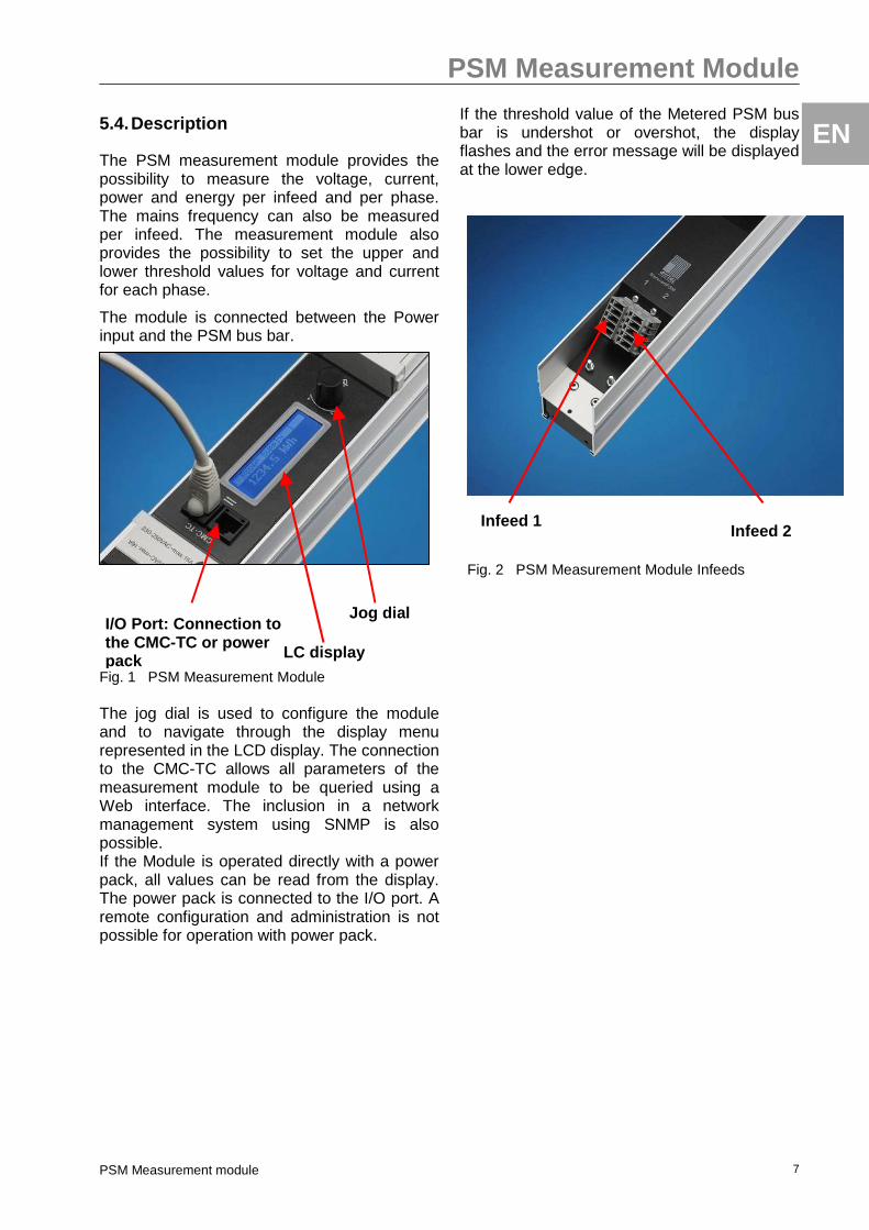
5.4. Description
The PSM measurement module provides the possibility to measure the voltage, current, power and energy per infeed and per phase. The mains frequency can also be measured per infeed. The measurement module also provides the possibility to set the upper and lower threshold values for voltage and current for each phase.
The module is connected between the Power input and the PSM bus bar.
Fig. 1 PSM Measurement Module The jog dial is used to configure the module and to navigate through the display menu represented in the LCD display. The connection to the CMC-TC allows all parameters of the measurement module to be queried using a Web interface. The inclusion in a network management system using SNMP is also possible. If the Module is operated directly with a power pack, all values can be read from the display. The power pack is connected to the I/O port. A remote configuration and administration is not possible for operation with power pack.
If the threshold value of the Metered PSM bus bar is undershot or overshot, the display flashes and the error message will be displayed at the lower edge.
Fig. 2 PSM Measurement Module Infeeds
Infeed 1 Infeed 2
Jog dial I/O Port: Connection to the CMC-TC or power pack LC display
PSM Measurement Module
PSM Measurement Modul 8
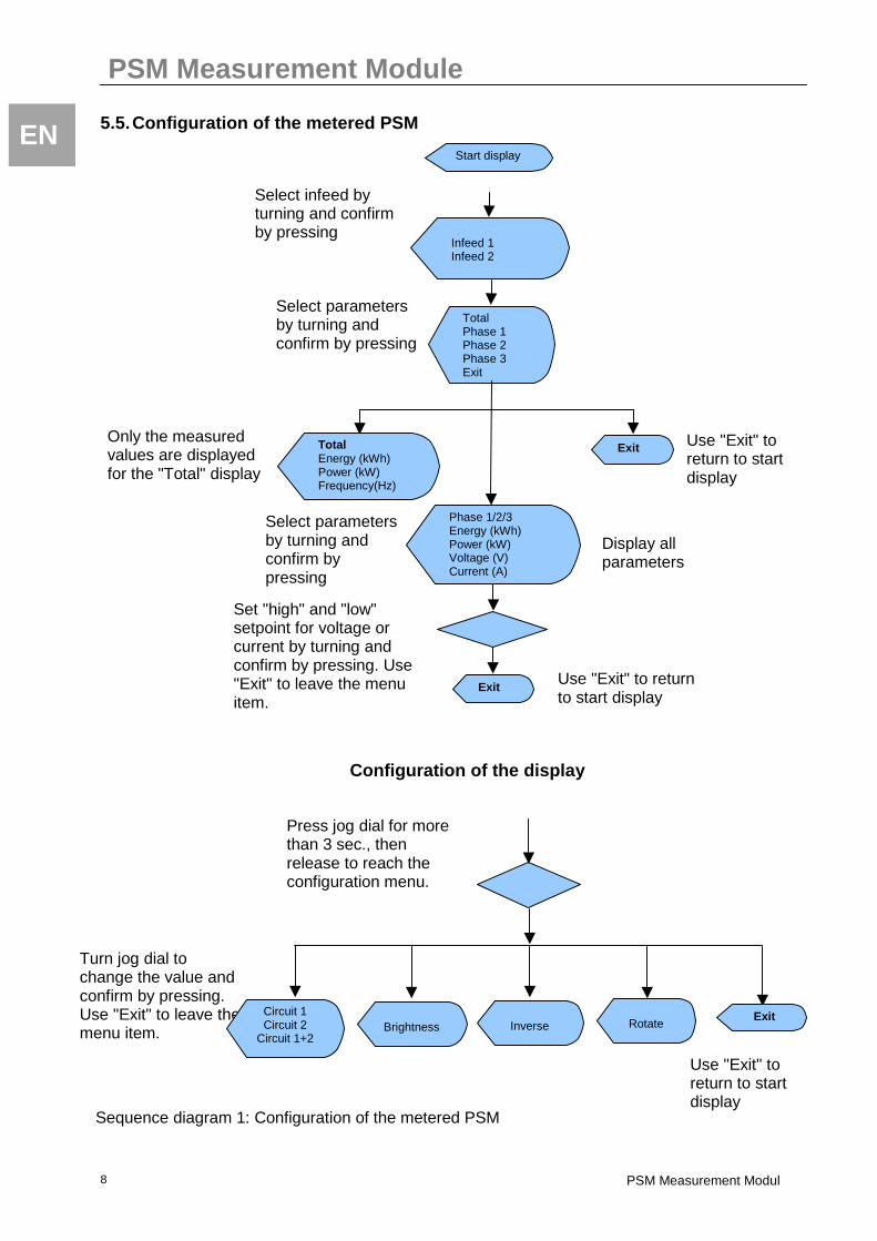
EN 5.5. Configuration of the metered PSM
Start display
Phase 1/2/3 Energy (kWh) Power (kW) Voltage (V) Current (A)
Set "high" and "low" setpoint for voltage or current by turning and confirm by pressing. Use "Exit" to leave the menu item.
Select infeed by turning and confirm by pressing
Press jog dial for more than 3 sec., then release to reach the configuration menu.
Turn jog dial to change the value and confirm by pressing. Use "Exit" to leave the menu item.
Configuration of the display
Total Phase 1 Phase 2 Phase 3 Exit
Select parameters by turning and confirm by pressing
Select parameters by turning and confirm by pressing
Infeed 1 Infeed 2
Total Energy (kWh) Power (kW) Frequency(Hz)
Exit Only the measured values are displayed for the "Total" display
Use "Exit" to return to start display
Exit Use "Exit" to return to start display
Use "Exit" to return to start display
Display all parameters
Rotate
Exit Brightness
Inverse
Circuit 1 Circuit 2
Circuit 1+2
Sequence diagram 1: Configuration of the metered PSM
PSM Measurement module 9
EN 5.6. Connection to the CMC-TC
5.6.1. Associated documents
The guide for the CMC-TC Processing Unit II (DK 7320.100) and its safety notes also apply together with this guide.
You can download the German version of the guide from: http://www.rittal.de/services_support/downloads/software.asp and the English version from: http://www.rittal.com/services_support/downloads/software.asp "IT Solutions" must be specified as product group.
To view the guide you require the Acrobat Reader program; Acrobat Reader can be downloaded from www.adobe.com
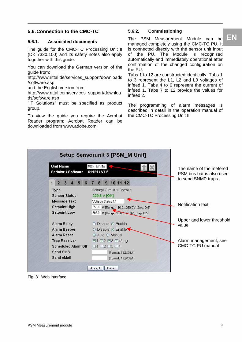
Fig. 3 Web interface
5.6.2. Commissioning
The PSM Measurement Module can be managed completely using the CMC-TC PU. It is connected directly with the sensor unit input of the PU. The Module is recognised automatically and immediately operational after confirmation of the changed configuration on the PU. Tabs 1 to 12 are constructed identically. Tabs 1 to 3 represent the L1, L2 and L3 voltages of infeed 1. Tabs 4 to 6 represent the current of infeed 1. Tabs 7 to 12 provide the values for infeed 2. The programming of alarm messages is described in detail in the operation manual of the CMC-TC Processing Unit II
The name of the metered PSM bus bar is also used to send SNMP traps. Notification text Upper and lower threshold value Alarm management, see CMC-TC PU manual
Maintenance
PSM Measurement Modul 10
EN 6. Maintenance The Rittal PSM is a maintenance-free system that does not need to be opened for the purposes of installation or operation. Opening the housing or any accessory components will void any warranty and liability claims.
7. Cleaning The Rittal PSM system can be cleaned using a dry cloth. The use of aggressive substances like cleanser's solvent, acids, etc. will destroy the system.
8. Disposal Because the Rittal PSM comprises predominantly of aluminium and plastic materials, it should be sent for proper disposal and recycling when it is no longer needed. The infeed cables should be removed before disposal.
9. Accessories for PSM system Model No.: Designation
DK 7000.684 PSM adaptor for TE rack
DK 7856.011 TS mounting kit for fixed installation
DK 7856.012 TS mounting kit for flexible installation
DK 7856.170 Over voltage protection
DK 7856.025 Connection cable, 3-phase CEKON 5-pole / 16 A
DK 7856.026 Connection cable, 1-phase CEKON 3-pole / 16 A
DK 7856.027 Connection cable, UPS, 1-phase C14/X-Com
Note!
More Rittal products for power distribution are shown on our homepage: www.rimatrix5.de
Technical Specifications
PSM Measurement module 11
EN
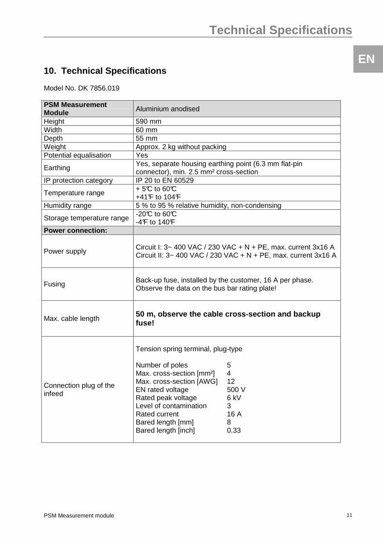
10. Technical Specifications Model No. DK 7856.019 PSM Measurement Module Aluminium anodised
Height 590 mm Width 60 mm Depth 55 mm Weight Approx. 2 kg without packing Potential equalisation Yes
Earthing Yes, separate housing earthing point (6.3 mm flat-pin connector), min. 2.5 mm² cross-section
IP protection category IP 20 to EN 60529
Temperature range + 5°C to 60°C +41°F to 104°F
Humidity range 5 % to 95 % relative humidity, non-condensing
Storage temperature range -20°C to 60°C -4°F to 140°F
Power connection:
Power supply
Circuit I: 3~ 400 VAC / 230 VAC + N + PE, max. current 3x16 A Circuit II: 3~ 400 VAC / 230 VAC + N + PE, max. current 3x16 A
Fusing
Back-up fuse, installed by the customer, 16 A per phase. Observe the data on the bus bar rating plate!
Max. cable length
50 m, observe the cable cross-section and backup fuse!
Connection plug of the infeed
Tension spring terminal, plug-type Number of poles 5 Max. cross-section [mm²] 4 Max. cross-section [AWG] 12 EN rated voltage 500 V Rated peak voltage 6 kV Level of contamination 3 Rated current 16 A Bared length [mm] 8 Bared length [inch] 0.33
Assembly instructions
PSM Measurement Modul 12
EN 11. Assembly instructions The Rittal PSM system must be installed in an enclosure or case system, which also provides protection against external influences. The length of lines should not exceed the lengths specified in the technical data for preventing losses caused by unnecessary line lengths.
In addition, the allowed ambient temperature and humidity ranges must be complied with, just as the IP protection category as required for the specific application. Compliance with a higher required IP protection category can be achieved by installation into an enclosure having the required protection category.
General notes to be observed when installing the PSM:
Warning!
When using accessories in connection with the Rittal PSM, the installation and operating instructions for the accessories and for the Rittal PSM must be observed.
Note!
During installation the existing national and regional regulations of the country, in which the Rittal PSM is to be installed and operated, must be observed.
Electrical shock danger! No objects must be inserted into the socket receptacles of the plug-in modules, nor into the connectors on the bus bar, as high electrical voltages may be present and may even result in the death of the persons involved.
Electrical shock danger!
Existing safety devices must not be made ineffective.
Electrical shock danger!
The Rittal PSM may only be operated with a PE connection. The PE connection is made at the terminal strip. The prerequisite here
is that the connecting cable is connected with a PE terminal on the mains side.
Electrical shock danger!
Before commencing any work on the Rittal PSM, it must always be disconnected from the power supply and secured to prevent inadvertent reconnection.
Warning!
The Rittal PSM must not be modified in any way. The internal wiring and connections made by the manufacturer must not be altered!
Warning!
The strain relief for the connection cable must be made in the immediate vicinity of the connection plug of the PSM bus bar. If the strain relief bracket cannot be attached to the base frame, a suitable punched section must be installed for the mounting of the strain relief bracket.
Warning!
The voltage of the electrical connection must correspond to the nominal values specified on the rating plate.
Note!
In the case of enclosures with a swing frame, mounting is only possible on the side of the enclosure where the swing frame hinges are fitted. Otherwise, the swing radius of the swing frame will be impaired.
Note!
In 600 mm wide enclosures, the rear 482.6 mm (19”) level may be

Assembly instructions
PSM Measurement module 13
EN slightly obstructed by the PSM bus bar. This must be taken into account when assembling the enclosure.
Note!
The DK 7856.011/012 mounting kit is required to assemble the TS enclosure. The two mounting brackets are screwed to the end covers of the PSM. The two fastening holes in the brackets permit mounting at various depths. It must be ensured, however, that the PSM remains readily accessible for installed punched section.
11.1. Mounting the measurement module
The Rittal PSM measurement module can be mounted in several different ways. A mounting kit with 2 brackets for mounting on an existing PSM bus bar is included in the scope of supply as standard. In addition, it is possible to mount the module directly in the enclosure using the standard PSM mounting kits for TS or TE enclosures.
Note!
The mounting kit DK 7856.011/012 (for TS) or DK 7000.684 (for TE) is not included in the scope of supply.
11.1.1. Mounting on the PSM bus bar The enclosed mounting brackets are suitable for two different mounting variants. Variant A: The mounting brackets are screwed to the measurement module with the enclosed screws, as shown in Fig. 4. Subsequently, the two U-profiles are slipped onto the PSM bus bar.
Fig. 4 Fitting and mounting the bracket Once the measurement module is positioned as required on the PSM bus bar, the two U-profiles are each clamped tight with the four enclosed screws, as shown in Fig. 5.
Fig. 5 Clamping to the PSM bus bar This mounting variant allows the module to be mounted at any chosen height on the bus bar. Variant B: The mounting brackets are screwed to the measurement module as shown in Fig. 6, and subsequently slipped onto the PSM bus bar.

Assembly instructions
PSM Measurement Modul 14
EN Note!
Due to the difficult access, it is necessary to insert the screws for clamping to the PSM bus bar into their corresponding holes before screwing the bracket to the measurement module.
Fig. 6 Fitting the bracket
Note!
The same brackets are used for Variants A and B; the upper and lower brackets are merely swapped.
The two U-profiles are finally each clamped tight at the corresponding points using the four enclosed screws.
Fig. 7 Clamping to the PSM bus bar The advantage of Variant B compared to Variant A is the positioning of the module on the PSM bus bar. Variant B permits a parallel arrangement at the top or bottom of the bus bar (see Fig. 7), which simplifies the electrical connection.
11.1.2. Mounting on a mounting plate The enclosed mounting brackets also permit mounting on mounting plates. The existing holes can simply be used to screw the measurement module to the mounting plate, as shown in Fig. 8. Fig. 8 Mounting on a mounting plate
Assembly instructions
PSM Measurement module 15
EN
E
AB
CD
F
G
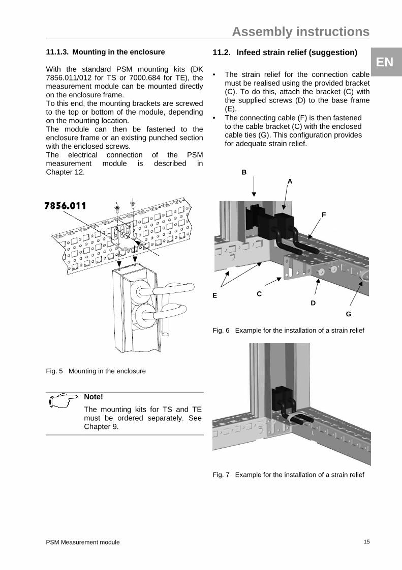
11.1.3. Mounting in the enclosure With the standard PSM mounting kits (DK 7856.011/012 for TS or 7000.684 for TE), the measurement module can be mounted directly on the enclosure frame. To this end, the mounting brackets are screwed to the top or bottom of the module, depending on the mounting location. The module can then be fastened to the enclosure frame or an existing punched section with the enclosed screws. The electrical connection of the PSM measurement module is described in Chapter 12.
Fig. 5 Mounting in the enclosure
Note!
The mounting kits for TS and TE must be ordered separately. See Chapter 9.
11.2. Infeed strain relief (suggestion)
• The strain relief for the connection cable
must be realised using the provided bracket (C). To do this, attach the bracket (C) with the supplied screws (D) to the base frame (E).
• The connecting cable (F) is then fastened to the cable bracket (C) with the enclosed cable ties (G). This configuration provides for adequate strain relief.
Fig. 6 Example for the installation of a strain relief
Fig. 7 Example for the installation of a strain relief
Assembly instructions
PSM Measurement Modul 16
EN Note!
The mounting of the strain relief may vary according to the specific installation situation in the enclosure.
Warning! The strain relief for the connection cable must be made in the immediate vicinity of the connection plug of the PSM bus bar. If the strain relief bracket cannot be attached to the base frame, a suitable punched section must be installed for the mounting of the strain relief bracket.
Note!
Where gland plates are fitted, the cable can also be tied directly to the base frame.
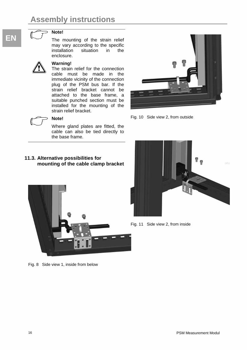
11.3. Alternative possibilities for mounting of the cable clamp bracket
Fig. 8 Side view 1, inside from below
Fig. 10 Side view 2, from outside
Fig. 11 Side view 2, from inside
Electrical connection of the bus bar
PSM Measurement module 17
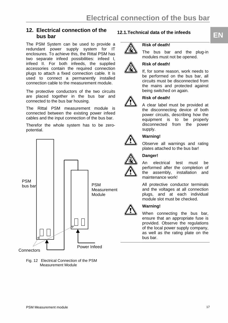
EN 12. Electrical connection of the
bus bar The PSM System can be used to provide a redundant power supply system for IT enclosures. To achieve this, the Rittal PSM has two separate infeed possibilities: infeed I, infeed II. For both infeeds, the supplied accessories contain the required connection plugs to attach a fixed connection cable. It is used to connect a permanently installed connection cable to the measurement module.
The protective conductors of the two circuits are placed together in the bus bar and connected to the bus bar housing.
The Rittal PSM measurement module is connected between the existing power infeed cables and the input connection of the bus bar.
Therefor the whole system has to be zero-potential.
Fig. 12 Electrical Connection of the PSM Measurement Module
12.1. Technical data of the infeeds
Risk of death!
The bus bar and the plug-in modules must not be opened.
Risk of death!
If, for some reason, work needs to be performed on the bus bar, all circuits must be disconnected from the mains and protected against being switched on again.
Risk of death!
A clear label must be provided at the disconnecting device of both power circuits, describing how the equipment is to be properly disconnected from the power supply.
Warning!
Observe all warnings and rating plates attached to the bus bar!
Danger!
An electrical test must be performed after the completion of the assembly, installation and maintenance work!
All protective conductor terminals and the voltages at all connection plugs, and at each individual module slot must be checked.
Warning!
When connecting the bus bar, ensure that an appropriate fuse is provided. Observe the regulations of the local power supply company, as well as the rating plate on the bus bar.
Power Infeed
PSM bus bar Measurem
ent Module
Connectors
PSM Measurement Module
Electrical connection of the bus bar
PSM Measurement Modul 18
EN
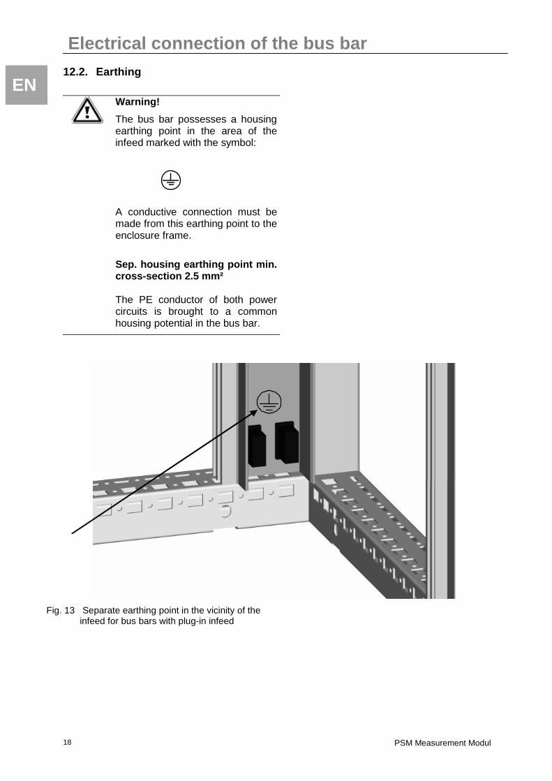
12.2. Earthing
Warning!
The bus bar possesses a housing earthing point in the area of the infeed marked with the symbol:
A conductive connection must be made from this earthing point to the enclosure frame.
Sep. housing earthing point min. cross-section 2.5 mm² The PE conductor of both power circuits is brought to a common housing potential in the bus bar.
Fig. 13 Separate earthing point in the vicinity of the infeed for bus bars with plug-in infeed
Electrical connection of the bus bar
PSM Measurement module 19
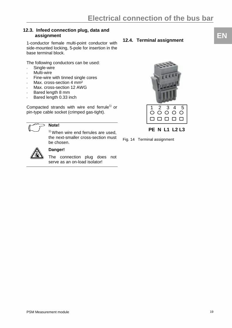
EN 12.3. Infeed connection plug, data and
assignment
1-conductor female multi-point conductor with side-mounted locking, 5-pole for insertion in the base terminal block. The following conductors can be used: - Single-wire - Multi-wire - Fine-wire with tinned single cores - Max. cross-section 4 mm² - Max. cross-section 12 AWG - Bared length 8 mm - Bared length 0.33 inch Compacted strands with wire end ferrule1) or pin-type cable socket (crimped gas-tight).
Note! 1) When wire end ferrules are used, the next-smaller cross-section must be chosen.
Danger!
The connection plug does not serve as an on-load isolator!
12.4. Terminal assignment
1 2 3 4 5
PE N L1 L2 L3
Fig. 14 Terminal assignment