power lab: a tool to learn electrical machines and power electronics
TRANSCRIPT

Power Lab: A Tool to LearnElectrical Machines andPower ElectronicsO. MONTERO-HERNANDEZ, A. RUGERIO DE LA ROSA, DAVID BAEZ-LOPEZ, R. ALEJOS,E. ENRIQUEZ
Department of Electronic Engineering, Universidad de las Americas-Puebla, A.P. 100 CP 72820 Cholula, Puebla, Mexico
Received 24 April 1996; accepted 2 April 1999
ABSTRACT: We describe a tool used in the teaching of power electronics that allowsusers to see how DC motors and AC/DC converters work without complicated circuits orarrangements. It also provides a user-friendly interface owing to its development under theWindows environment. The tool described is called Power Lab. The goal of the tool is tointroduce students to the DC motor control area, showing some functions for the motor suchas full voltage starting, reduced starting voltage, stopping, reverse rotation, and speedregulation in a closed loop. Through the achievement of the motor’s function, students canalso observe the performance of an AC/DC power converter with phase-angle control andon/off control. Power Lab has the capability to work either as a stand-alone tool orconnected to a power stage. Several examples describe the applications of Power Lab.© 2000 John Wiley & Sons, Inc. Comput Appl Eng Educ 7: 213–220, 1999
Keywords: electrical engineering education; industrial control; automatic control
INTRODUCTION
Computer-based education and training (CBET) is aninteresting option in engineering education which hashad rapid growth in the past several years [1,2]. Oneimportant difference between television education andCBET lies in the fact that CBET has the capability ofbeing more flexible and interactive in most cases.With these advantages, CBET is an attractive optionin some courses, such as in electrical machines andpower electronics, in which there exist the risks ofshort circuits, damage to devices and equipment, and,most important, injury to users. The tool presented
here, Power Lab, is intended to be the first approachfor students in DC motors and AC/DC power con-verters [3–5]. Power Lab is software developed underthe Windows environment in Microsoft Visual Basicwhich can operate in any of three modes: as a stand-alone tool, in visualization mode, or connected to aDC motor through an external power stage. A motorcan be controlled using either a phase-angle control,or on/off control, or an integral control [6,7]. Severalexamples are shown to illustrate some features ofPower Lab.
PACKAGE DESCRIPTION
Power Lab was designed under the Windows envi-ronment; therefore, its usage is Windows oriented.
Correspondence to D. Ba´ez-Lopez ([email protected]).© 2000 John Wiley & Sons, Inc.
213

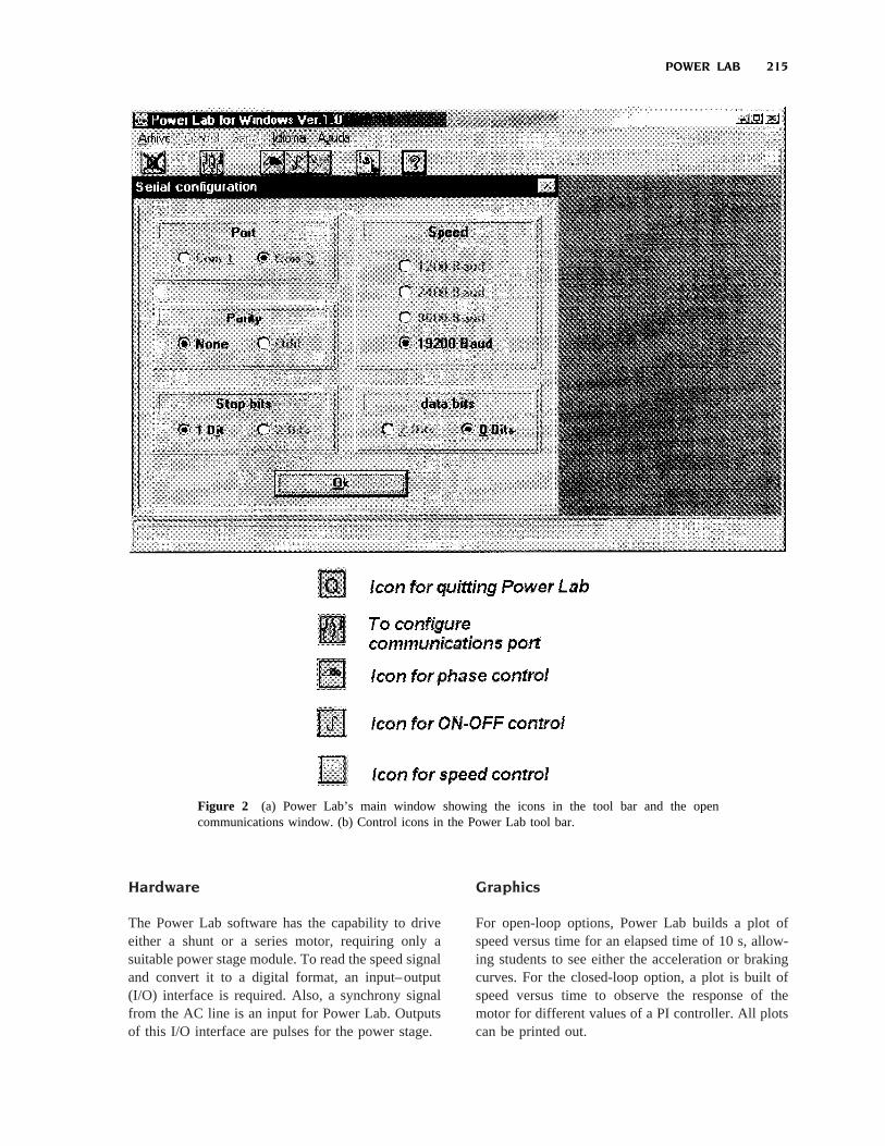
The first window, shown in Figure 1, is the titlewindow for Power Lab, which allows students tochoose the English or Spanish language. The secondwindow, which is the main window for Power Lab,has icons for Power Lab applications. This main win-dow is shown in Figure 2(a). Each icon is explained inFigure 2(b). The applications for Power Lab are foropen- or closed-loop applications. The open-loop ap-plications are for phase-angle control and on/off con-trol [6]. The closed-loop application is for speed reg-ulation. Both types of applications are used to drive anAC/DC converter. With a minimum of changes, thisconverter can also be used as an AC/AC controller. Inaddition, there are icons to change between the En-glish or Spanish language, an icon for a Help menu,and an icon to quit from the Power Lab software.
OPEN-LOOP CHARACTERISTICS
Phase-Angle Control
When a student selects the phase-angle control option,the window shown in Figure 3 is displayed. Thiswindow has five main sections: bar menu, animationwindow, speed window, functions window, and scrollbar. These sections are described below.
Bar Menu. There are four options in the bar menu:(1) quit from phase-angle control and return to themain Power Lab window, (2) print current window,(3) see the starting acceleration ramp, and (4) see thebraking curve. The last two options are not enabled inthe visualization mode.
Animation Window. This part of the window workslike a virtual oscilloscope which shows ideal wave-
forms of rectified AC, pulses generated and sent to thepower stage, and the output voltage. Students canmodify the base time to change the number of wave-form cycles displayed.
Speed Window.This window shows the actual motorspeed; it will display zeros when students are workingin the visualization mode.
Function Buttons. With these buttons, students canchoose among the following options for the motor: afull starting voltage, a reduced starting voltage, stop-ping, and reversal of motor rotation.
Scroll Bar. This bar is used to adjust the value of thefiring angle. The firing angle value can be modifiedeither with the scroll bar or by entering an angle valuewith the keyboard.
On/Off Control
The window for this operation mode is shown inFigure 4. In this case, students can modify the powersupplied to the motor by adjusting the on/off ratiowith the ON Cycles and OFF Cycles scroll bars.
This mode allows only for full voltage starting,stopping, and reversal of motor rotation. In addition,in the animation window, students can modify thenumber of waveforms to be displayed.
CLOSED-LOOP CHARACTERISTICS
Speed regulation for the motor is achieved using aspeed feedback signal and a PI controller. Figure 5shows the window where students may modify thespeed Setpoint or the values of the PI controller byusing the scroll bars. In addition, an icon is availableto reverse the rotation direction of the motor. Thisoption cannot work in the visualization mode becausea speed feedback signal is needed to close the loop.
ADDITIONAL FEATURES
Help Option
Power Lab includes a Help option that can be veryuseful for students who require an explanation ofPower Lab and all the stages involved. Some topics inthe Help option are Power stage, DC motors, PIcontrollers, etc. The help option icon can be used atany time and from any window.
Figure 1 Power Lab’s first window, showing the blockdiagram of the system. Users can choose the language here.
214 MONTERO-HERNANDEZ ET AL.
Hardware
The Power Lab software has the capability to driveeither a shunt or a series motor, requiring only asuitable power stage module. To read the speed signaland convert it to a digital format, an input–output(I/O) interface is required. Also, a synchrony signalfrom the AC line is an input for Power Lab. Outputsof this I/O interface are pulses for the power stage.
Graphics
For open-loop options, Power Lab builds a plot ofspeed versus time for an elapsed time of 10 s, allow-ing students to see either the acceleration or brakingcurves. For the closed-loop option, a plot is built ofspeed versus time to observe the response of themotor for different values of a PI controller. All plotscan be printed out.
Figure 2 (a) Power Lab’s main window showing the icons in the tool bar and the opencommunications window. (b) Control icons in the Power Lab tool bar.
POWER LAB 215

ADVANTAGES OF POWER LAB
Some advantages of Power Lab are
1. Reduction of costs in components and devicesdamaged by inexperienced users
2. Easy understanding of phenomena in powerstage AC/DC converters
3. No need for a dedicated pulse generator foreach technique to be learned
4. Superior flexibility of software pulse genera-tors over hardware pulse generators
5. No high-voltage risk exposure to students6. Achievement of motor’s functions by pressing
keys instead of changing terminals
7. Use of either shunt motor or series motors8. Help option, which allows students to learn
control concepts and Power Lab usage on-line9. Validations to avoid electrical problems with
novice students10. Ease of use; may be used in either visualiza-
tion or experimental mode11. Ability to allow changes on-line, such as
changing the speed of a motor, reverse rota-tion, and adjusting values of a PI controller inclosed-loop applications
12. Also on-line, language changes posible be-tween either English and Spanish
13. Ability to print current window
Figure 3 Window for phase-angle control.
Figure 4 Window for on/off control.
216 MONTERO-HERNANDEZ ET AL.

Figure 6 (a) Waveform for phase-angle control. (b) Parameters for phase-angle control.
Figure 5 Window for speed regulation.
POWER LAB 217

EXAMPLES
Example 1: Phase-Angle Control
As our first example, Figure 6(a) shows through PowerLab how the trigger control signal actually looks. Theupper plot shows the rectified voltage; the second plotanimates virtually the moment in which the pulses areapplied to the thyristors; and finally, the bottom plot
represents the final voltage that is fed to the motor shield.In this case, the pulses are applied at 90°, the speed is2046 rpm, the rotation direction is clockwise, and thecorrection factor is null, as shown in Figure 6(b).
Example 2: On/Off Control
Our second example is of an on/off control. Figure7(a) shows the window provided by Power Lab. In
Figure 7 (a) AC-rectified input for on/off control. (b) Waveforms applied for on/off control. (c)Parameters for on/off control.
218 MONTERO-HERNANDEZ ET AL.

this case, several half-rectified cycles are enabled (on)and several are disabled (off) to modify the DC av-erage resulting voltage. The on/off control also hasthree plots, shown in Figure 7(a). For this example, inFigure 7(b) eight half-rectified cycles are shown: threeon cycles and two off cycles in the second plot, andthe final voltage in the third plot. The speed is 1492rpm and the direction of the motor rotation is clock-wise, as can be seen in the control panel in Figure7(c).
Example 3: Adjustable Speed Control
In this example, Figure 8(a) shows the control panel ofthe adjustable speed control which provides and keeps a
constant speed in the motor, with or without a load. Inthis case, the set point has been set to 1100. The pro-portional constant gives a gain to the control action. Theintegral constant ensures zero steady-state error. Thespeed panel shows the actual speed of the motor in realtime. The display shows the time when the motor speedis 1125 rpm. In addition, Power Lab plots the speedresponse in the first 30 s of its operation. For thisexample, this plot is shown in Figure 8(b).
CONCLUSIONS
We describe a software tool that offers students aquick and easy introduction to simulation and lab
Figure 8 (a) Parameters for speed regulation control. (b) Speed response in the first 30 s ofoperation.
POWER LAB 219
experiments related to electrical machines and powerelectronics, using a tool named Power Lab. This toolwas designed for the Windows environment; thus, it iseasy to use. Its main advantages are a reduction incost that may result from damage to equipment andparts in a real experiment, avoidance of injuries tonovice users owing to exposure to high voltage, andrapid understanding of the topics developed andtaught in the classroom.
REFERENCES
[1] T. C. Huang. M. A El-sharkawi, and M. Chen, Labo-ratory setup for instruction and research in electric
drives control, IEEE Trans Power Systems (1) 5(1990), 331–337.
[2] D. Baez-Lopez and O. Montero-Herna´ndez, An in-terdisciplinary curriculum in electronics and com-puter engineering, IEEE Trans Educ (1) 36 (1993),184 –186.
[3] B. J. Chalmers, Electric motor handbook, Butter-worths, London, 1988.
[4] R. J. Lawrie, Electric motor manual, McGraw-HillNew York, 1987.
[5] M.G. Say and E. Openshaw Taylor, Direct currentmachines, 2nd ed., Wiley, New York, 1980.
[6] R. Isermann, Digital control systems, Springer-Verlag,Berlin, 1991.
[7] C. H. Houpis and G. B. Lamont, Digital control sys-tems, McGraw-Hill, New York, 1985.
BIOGRAPHIES
Oscar Montero-Hernandez received theBS degree in electrical engineering from In-stituto Tecnolo´gico de Veracruz, Veracruz,Mexico, in 1987 and the MS degree from theInstituto Tecnolo´gico de la Laguna, Torreo´n,Mexico, in 1989. From 1989 to 1990, he waswith Centro Nacional de Investigacio´n y De-sarrollo Tecnolo´gico y Desarrollo Tecno-logico in Cuernavaca, Mexico, as an assis-
tant professor in the graduate program in electrical engineering.From 1990 to 1996, he was with the Departamento de Ingenierı´aElectronica of the Universidad de las Ame´ricas, Puebla, Mexico, asan associate professor. Currently, he is pursuing a doctoral degreeat Texas A&M University, College Station, Texas. His areas ofinterest are power electronics, electric drives, and education.
David Baez-Lopez received the BS degreein physics with honors from the AutonomousUniversity of Puebla, Mexico, in 1973, andthe MS and PhD degrees in electrical engi-neering from the University of Arizona, Tuc-son, in 1976 and 1979, respectively. From1979 to 1984, he was a researcher with theInstituto Nacional de Astrofı´sica Optica yElectronica, Tonantzintla, Mexico, and be-
came head of the Department of Electronics in 1983. In 1985, hejoined the Department of Electrical Engineering of the Universidadde las Ame´ricas-Puebla, Mexico, where he is currently a professorand was department chairman from 1988 to 1996. He spent asabbatical leave at the Instituto Nacional de Astrofı´sica Optica yElectronica, Tonantzintla, Mexico, during the 1997–1998 academicyear. His interests are in the areas of education on circuits andsystems, active filters, and digital image processing. He was thegeneral chairman of the IEEE MEXICON’94 conference and isfounder of the International Conference on Electronic Engineering,held in Puebla, Mexico, every other year. He has published over 80papers in journals and conference proceedings and is author of thebook Circuit Analysis Using SPICE, published in 1995 in Mexicoby Ediciones Alfaomega (in Spanish)
A. Rugerio de la Rosa(Biographical sketch and photograph notavailable.)
Ruben Alejos-Palomares received the BSdegree in electrical engineering from Mina-titlan Technological Institute, at Minatitla´n,Veracruz, Mexico, in 1987, and the MS andPhD degrees from the National Institute ofAstrophysics, Optics, and Electronics at To-nantzintla, Puebla, Mexico, in 1990 and1999, respectively. Since 1988 he has beenwith the Department of Electrical Engineer-
ing at the Universidad de las Ame´ricas–Puebla as an associateprofessor. His areas of interest are instrumentation, measurement,and control.
Ernesto Enriquez was born in Puebla onJuly 1, 1975. He was an exchange student inIronton High School (Ironton, Ohio) from1990 to 1991. He worked in VolkswagenA.G. in Kassel, Germany, during his 1-yearexchange program at the Uinversita¨t Gesa-mthochshule Kassel. He has been a studentmember of the IEEE since 1994. In June1996, he participated in the first contest of
Web pages in Mexico organized by Internet World Mexico 96, andin November 1996 he gave a conference on “How to Make a WEBPage and Best Sites on the Web,” at the first International Sympo-sium on Information Technology at Tuxtla Gutierrez, Chiapas. Hewas a member of the Electrical and Electronics Engineering Stu-dents Society in 1996–1997. He worked with the consultant com-pany Grupo Orion to review network equipment at the VolkswagenPlant in Mexico to approve Y2K standards in October 1998. Cur-rently, he is finishing his BS thesis, “Simulation of the ATMnetwork of the Universidad de las Ame´ricas–Puebla using SPEC-TRUM (Network Monitor) and COMNET III (Network Simula-tor).” At the same time, he is working at Procter & Gamble,Apizaco, Tlaxcala Plant, on work-integrated systems.
220 MONTERO-HERNANDEZ ET AL.