portland cement manufacturing industry neshap …...portland cement manufacturing industry neshap...
TRANSCRIPT

Portland Cement Manufacturing Industry NESHAP Summary of Requirements1
Requirements for Kiln at Major Source of HAP
Constructed on or before May 6, 2009
Applicability/Affected Sources: 63.1340(b)(1)
§63.1340 What parts of my plant does this subpart cover?
(b) The affected sources subject to this subpart are:
(1) Each kiln including alkali bypasses and inline coal mills, except for kilns that burn hazardous
waste and are subject to and regulated under subpart EEE of this part;
Emission and Work Practice Standards – General: 63.1343(a)
§63.1343 What standards apply to my kilns, clinker coolers, raw material dryers, and open clinker
storage piles?
(a) General. The provisions in this section apply to each kiln and any alkali bypass associated with
that kiln, clinker cooler, raw material dryer, and open clinker storage pile. All D/F, HCl, and total
hydrocarbon (THC) emissions limit are on a dry basis. The D/F, HCl, and THC limits for kilns are
corrected to 7 percent oxygen. All THC emissions limits are measured as propane. Standards for mercury
and THC are based on a rolling 30-day average. If using a CEMS to determine compliance with the HCl
standard, this standard is based on a rolling 30-day average. You must ensure appropriate corrections for
moisture are made when measuring flow rates used to calculate mercury emissions. The 30-day period
means all operating hours within 30 consecutive kiln operating days excluding periods of startup and
shutdown. All emissions limits for kilns, clinker coolers, and raw material dryers currently in effect that
are superseded by the limits below continue to apply until the compliance date of the limits below, or
until the source certifies compliance with the limits below, whichever is earlier.
Emission and Work Practice Standards – Emission Limits for PM, D/F, Mercury, THC:
63.1343(b)(1), Table 1 #1
§63.1343 What standards apply to my kilns, clinker coolers, raw material dryers, and open clinker
storage piles?
(b) Kilns, clinker coolers, raw material dryers, raw mills, and finish mills. (1) The emissions limits for
these sources are shown in Table 1.
1 Disclaimer: The content provided in this software tool is intended solely as an aid in assessing requirements for
compliance under the National Emissions Standards for Hazardous Air Pollutants from the Portland Cement
Manufacturing Industry, 40 CFR part 63 subpart LLL. Any variation between the rule and the information provided
in this tool is unintentional, and, in the case of such variations, the requirements of the rule govern. Use of this tool
does not constitute an assessment by the EPA of the applicability of the rule to any particular facility. In any
particular case, the EPA will make its assessment by applying the law and regulations to the specific facts of the
case.

Table 1—Emissions Limits for Kilns, Clinker Coolers, Raw Material Dryers, Raw and Finish Mills
If your
source is a
(an):
And the
operating
mode is:
And if is
located at
a:
Your
emissions
limits are:
And the units of
the emissions limit
are:
The oxygen
correction factor
is:
1. Existing
kiln
Normal
operation
Major or
area source
PM1 0.07 lb/ton clinker NA.
D/F2 0.2 ng/dscm (TEQ) 7 percent.
Mercury 55 lb/MM tons clinker NA.
THC34 24 ppmvd 7 percent.
1The initial and subsequent PM performance tests are performed using Method 5 or 5I and consist of
three test runs.
2If the average temperature at the inlet to the first PM control device (fabric filter or electrostatic
precipitator) during the D/F performance test is 400 °F or less, this limit is changed to 0.40 ng/dscm
(TEQ).
3Measured as propane.
4Any source subject to the 24 ppmvd THC limit may elect to meet an alternative limit of 12 ppmvd
for total organic HAP.
Emission and Work Practice Standards – Emission Limits for HCl: 63.1343(b)(1), Table 1 #2
§63.1343 What standards apply to my kilns, clinker coolers, raw material dryers, and open clinker
storage piles?
(b) Kilns, clinker coolers, raw material dryers, raw mills, and finish mills. (1) The emissions limits for
these sources are shown in Table 1.
Table 1—Emissions Limits for Kilns, Clinker Coolers, Raw Material Dryers, Raw and Finish Mills
If your
source is a
(an):
And the
operating
mode is:
And if is
located at
a:
Your
emissions
limits are:
And the units of
the emissions limit
are:
The oxygen
correction factor
is:
2. Existing
kiln
Normal
operation
Major
source
HCl 3 ppmvd 7 percent.
Emission and Work Practice Standards - PM Emission Limit When There is an Alkali Bypass and/or an Inline Coal Mill with a Separate Stack Associated with a Kiln: 63.1343(b)(2)
§63.1343 What standards apply to my kilns, clinker coolers, raw material dryers, and open clinker
storage piles?
(b) Kilns, clinker coolers, raw material dryers, raw mills, and finish mills.
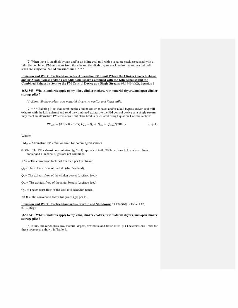
(2) When there is an alkali bypass and/or an inline coal mill with a separate stack associated with a
kiln, the combined PM emissions from the kiln and the alkali bypass stack and/or the inline coal mill
stack are subject to the PM emissions limit. * * *
Emission and Work Practice Standards - Alternative PM Limit Where the Clinker Cooler Exhaust
and/or Alkali Bypass and/or Coal Mill Exhaust are Combined with the Kiln Exhaust and the Combined Exhaust is Sent to the PM Control Device as a Single Stream: 63.1343(b)(2), Equation 1
§63.1343 What standards apply to my kilns, clinker coolers, raw material dryers, and open clinker
storage piles?
(b) Kilns, clinker coolers, raw material dryers, raw mills, and finish mills.
(2) * * * Existing kilns that combine the clinker cooler exhaust and/or alkali bypass and/or coal mill
exhaust with the kiln exhaust and send the combined exhaust to the PM control device as a single stream
may meet an alternative PM emissions limit. This limit is calculated using Equation 1 of this section:
����� = �0.0060�1.65���� + �� + ��� + ����/�7000� (Eq. 1)
Where:
PMalt = Alternative PM emission limit for commingled sources.
0.006 = The PM exhaust concentration (gr/dscf) equivalent to 0.070 lb per ton clinker where clinker
cooler and kiln exhaust gas are not combined.
1.65 = The conversion factor of ton feed per ton clinker.
Qk = The exhaust flow of the kiln (dscf/ton feed).
Qc = The exhaust flow of the clinker cooler (dscf/ton feed).
Qab = The exhaust flow of the alkali bypass (dscf/ton feed).
Qcm = The exhaust flow of the coal mill (dscf/ton feed).
7000 = The conversion factor for grains (gr) per lb.
Emission and Work Practice Standards – Startup and Shutdown: 63.1343(b)(1) Table 1 #3,
63.1346(g)
§63.1343 What standards apply to my kilns, clinker coolers, raw material dryers, and open clinker
storage piles?
(b) Kilns, clinker coolers, raw material dryers, raw mills, and finish mills. (1) The emissions limits for
these sources are shown in Table 1.

Table 1—Emissions Limits for Kilns, Clinker Coolers, Raw Material Dryers, Raw and Finish Mills
If your
source is a
(an):
And the
operating
mode is:
And if is
located at
a:
Your emissions
limits are:
And the units of
the emissions limit
are:
The oxygen
correction factor
is:
3. Existing
kiln
Startup and
shutdown
Major or
area source
Work practices
(63.1346(g))
NA NA.
§63.1346 Operating limits for kilns.
(g) During periods of startup and shutdown you must meet the requirements listed in (g)(1) through
(4) of this section.
(1) During startup you must use any one or combination of the following clean fuels: natural gas,
synthetic natural gas, propane, distillate oil, synthesis gas (syngas), and ultra-low sulfur diesel (ULSD)
until the kiln reaches a temperature of 1200 degrees Fahrenheit.
(2) Combustion of the primary kiln fuel may commence once the kiln temperature reaches 1200
degrees Fahrenheit.
(3) All dry sorbent and activated carbon systems that control hazardous air pollutants must be turned
on and operating at the time the gas stream at the inlet to the baghouse or ESP reaches 300 degrees
Fahrenheit (five minute average) during startup. Temperature of the gas stream is to be measured at the
inlet of the baghouse or ESP every minute. Such injection systems can be turned off during shutdown.
Particulate control and all remaining devices that control hazardous air pollutants should be operational
during startup and shutdown.
(4) You must keep records as specified in §63.1355 during periods of startup and shutdown.
Operating Limits – Kiln Subject to D/F Emissions Limit Under 63.1343: 63.1346(a)-(e)
§63.1346 Operating limits for kilns.
(a) The owner or operator of a kiln subject to a D/F emissions limitation under §63.1343 must operate
the kiln such that the temperature of the gas at the inlet to the kiln PM control device (PMCD) and alkali
bypass PMCD, if applicable, does not exceed the applicable temperature limit specified in paragraph (b)
of this section. The owner or operator of an in-line kiln/raw mill subject to a D/F emissions limitation
under §63.1343 must operate the in-line kiln/raw mill, such that:
(1) When the raw mill of the in-line kiln/raw mill is operating, the applicable temperature limit for the
main in-line kiln/raw mill exhaust, specified in paragraph (b) of this section and established during the
performance test when the raw mill was operating, is not exceeded, except during periods of startup and
shutdown when the temperature limit may be exceeded by no more than 10 percent.
(2) When the raw mill of the in-line kiln/raw mill is not operating, the applicable temperature limit for
the main in-line kiln/raw mill exhaust, specified in paragraph (b) of this section and established during the
performance test when the raw mill was not operating, is not exceeded, except during periods of
startup/shutdown when the temperature limit may be exceeded by no more than 10 percent.

(3) If the in-line kiln/raw mill is equipped with an alkali bypass, the applicable temperature limit for
the alkali bypass specified in paragraph (b) of this section and established during the performance test,
with or without the raw mill operating, is not exceeded, except during periods of startup/shutdown when
the temperature limit may be exceeded by no more than 10 percent.
(b) The temperature limit for affected sources meeting the limits of paragraph (a) of this section or
paragraphs (a)(1) through (a)(3) of this section is determined in accordance with §63.1349(b)(3)(iv).
(c) For an affected source subject to a D/F emissions limitation under §63.1343 that employs sorbent
injection as an emission control technique for D/F control, you must operate the sorbent injection system
in accordance with paragraphs (c)(1) and (2) of this section.
(1) The rolling three-hour average activated sorbent injection rate must be equal to or greater than the
sorbent injection rate determined in accordance with §63.1349(b)(3)(vi).
(2) You must either:
(i) Maintain the minimum activated carbon injection carrier gas flow rate, as a rolling three-hour
average, based on the manufacturer's specifications. These specifications must be documented in the test
plan developed in accordance with §63.7(c), or
(ii) Maintain the minimum activated carbon injection carrier gas pressure drop, as a rolling three-hour
average, based on the manufacturer's specifications. These specifications must be documented in the test
plan developed in accordance with §63.7(c).
(d) Except as provided in paragraph (e) of this section, for an affected source subject to a D/F
emissions limitation under §63.1343 that employs carbon injection as an emission control technique you
must specify and use the brand and type of sorbent used during the performance test until a subsequent
performance test is conducted, unless the site-specific performance test plan contains documentation of
key parameters that affect adsorption and the owner or operator establishes limits based on those
parameters, and the limits on these parameters are maintained.
(e) For an affected source subject to a D/F emissions limitation under §63.1343 that employs carbon
injection as an emission control technique you may substitute, at any time, a different brand or type of
sorbent provided that the replacement has equivalent or improved properties compared to the sorbent
specified in the site-specific performance test plan and used in the performance test. The owner or
operator must maintain documentation that the substitute sorbent will provide the same or better level of
control as the original sorbent.
Operating Limits – Conditions on Use of Fly Ash: 63.1346(f)
§63.1346 Operating limits for kilns.
(f) No kiln may use as a raw material or fuel any fly ash where the mercury content of the fly ash has
been increased through the use of activated carbon, or any other sorbent, unless the facility can
demonstrate that the use of that fly ash will not result in an increase in mercury emissions over baseline
emissions (i.e., emissions not using the fly ash). The facility has the burden of proving there has been no
emissions increase over baseline. Once the kiln is in compliance with a mercury emissions limit specified
in §63.1343, this paragraph no longer applies.

Operating Limits – Startup and Shutdown: 63.1346(g)
§63.1346 Operating limits for kilns.
(g) During periods of startup and shutdown you must meet the requirements listed in (g)(1) through
(4) of this section.
(1) During startup you must use any one or combination of the following clean fuels: natural gas,
synthetic natural gas, propane, distillate oil, synthesis gas (syngas), and ultra-low sulfur diesel (ULSD)
until the kiln reaches a temperature of 1200 degrees Fahrenheit.
(2) Combustion of the primary kiln fuel may commence once the kiln temperature reaches 1200
degrees Fahrenheit.
(3) All dry sorbent and activated carbon systems that control hazardous air pollutants must be turned
on and operating at the time the gas stream at the inlet to the baghouse or ESP reaches 300 degrees
Fahrenheit (five minute average) during startup. Temperature of the gas stream is to be measured at the
inlet of the baghouse or ESP every minute. Such injection systems can be turned off during shutdown.
Particulate control and all remaining devices that control hazardous air pollutants should be operational
during startup and shutdown.
(4) You must keep records as specified in §63.1355 during periods of startup and shutdown.
Operation and Maintenance Plan: 63.1347
§63.1347 Operation and maintenance plan requirements.
(a) You must prepare, for each affected source subject to the provisions of this subpart, a written
operations and maintenance plan. The plan must be submitted to the Administrator for review and
approval as part of the application for a part 70 permit and must include the following information:
(1) Procedures for proper operation and maintenance of the affected source and air pollution control
devices in order to meet the emissions limits and operating limits, including fugitive dust control
measures for open clinker piles of §§63.1343, 63.1345, and 63.1346. Your operations and maintenance
plan must address periods of startup and shutdown.
(2) Corrective actions to be taken when required by paragraph §63.1350(f)(3);
(3) Procedures to be used during an inspection of the components of the combustion system of each
kiln and each in-line kiln raw mill located at the facility at least once per year.
(b) Failure to comply with any provision of the operations and maintenance plan developed in
accordance with this section is a violation of the standard.
Compliance Requirements – Initial Performance Test Requirements: 63.1348(a), (a)(1), (3) - (7)
§63.1348 Compliance requirements.
(a) Initial Performance Test Requirements. For an affected source subject to this subpart, you must
demonstrate compliance with the emissions standards and operating limits by using the test methods and
procedures in §§63.1349 and 63.7. Any cement kiln that has been subject to the requirements of subpart
CCCC or subpart DDDD of 40 CFR Part 60, and is now electing to cease burning nonhazardous solid

waste and become subject to this subpart, must meet all the initial compliance testing requirements each
time it becomes subject to this subpart, even if it was previously subject to this subpart.
NOTE TO PARAGRAPH (a): The first day of the 30 operating day performance test is the first day after
the compliance date following completion of the field testing and data collection that demonstrates that
the CPMS or CEMS has satisfied the relevant CPMS performance evaluation or CEMS performance
specification (e.g., PS 2, 12A, or 12B) acceptance criteria. The performance test period is complete at the
end of the 30th consecutive operating day. See §63.1341 for definition of operating day and
§63.1348(b)(1) for the CEMS operating requirements. The source has the option of performing the
compliance test earlier then the compliance date if desired.
(1) PM Compliance. If you are subject to limitations on PM emissions under §63.1343(b), you must
demonstrate compliance with the PM emissions standards by using the test methods and procedures in
§63.1349(b)(1).
(3) D/F compliance. (i) If you are subject to limitations on D/F emissions under §63.1343(b), you
must demonstrate initial compliance with the D/F emissions standards by using the performance test
methods and procedures in §63.1349(b)(3). The owner or operator of a kiln with an in-line raw mill must
demonstrate initial compliance by conducting separate performance tests while the raw mill is operating
and the raw mill is not operating. The D/F concentration must be determined for each run and the
arithmetic average of the concentrations measured for the three runs must be calculated to determine
compliance. The owner or operator of a kiln with an in-line raw mill must demonstrate compliance by
conducting separate performance tests while the raw mill is operating and while the raw mill is not
operating. Determine the D/F TEQ concentration for each run and calculate the arithmetic average of the
TEQ concentrations measured for the three runs to determine continuous compliance.
(ii) If you are subject to a D/F emissions limitation under §63.1343(b), you must demonstrate
compliance with the temperature operating limits specified in §63.1346 by using the performance test
methods and procedures in §63.1349(b)(3)(ii) through (b)(3)(iv). Use the arithmetic average of the
temperatures measured during the three runs to determine the applicable temperature limit.
(iii) If activated carbon injection is used and you are subject to a D/F emissions limitation under
§63.1343(b), you must demonstrate compliance with the activated carbon injection rate operating limits
specified in §63.1346 by using the performance test methods and procedures in §63.1349(b)(3)(v).
(iv) If activated carbon injection is used, you must also develop a carrier gas parameter (either the
carrier gas flow rate or the carrier gas pressure drop) during the initial performance test and updated
during any subsequent performance test conducted under §63.1349(b)(3) that meets the requirements of
§63.1349(b)(3)(vi). Compliance is demonstrated if the system is maintained within ±5 percent accuracy
during the performance test determined in accordance with the procedures and criteria submitted for
review in your monitoring plan required in section 63.1350(p).
(4)(i) THC Compliance. If you are subject to limitations on THC emissions under §63.1343(b), you
must demonstrate compliance with the THC emissions standards by using the performance test methods
and procedures in §63.1349(b)(4)(i). You must use the average THC concentration obtained during the
first 30 kiln operating days after the compliance date of this rule to determine initial compliance.
(ii) Total Organic HAP Emissions Tests. If you elect to demonstrate compliance with the total organic
HAP emissions limit under §63.1343(b) in lieu of the THC emissions limit, you must demonstrate
compliance with the total organic HAP emissions standards by using the performance test methods and
procedures in §63.1349(b)(7).

(iii) If you are demonstrating initial compliance, you must conduct the separate performance tests as
specified in §63.1349(b)(7) while the raw mill of the inline kiln/raw mill is operating and while the raw
mill of the inline kiln/raw mill is not operating.
(iv) The time weighted average total organic HAP concentration measured during the separate initial
performance test specified by §63.1349(b)(7) must be used to determine initial compliance.
(v) The time weighted average THC concentration measured during the initial performance test
specified by §63.1349(b)(4) must be used to determine the site-specific THC limit. Using the fraction of
time the inline kiln/raw mill is on and the fraction of time that the inline kiln/raw mill is off, calculate this
limit as a time weighted average of the THC levels measured during raw mill on and raw mill off testing
using one of the two approaches in §63.1349(b)(7)(vii) or (viii) depending on the level of organic HAP
measured during the compliance test.
(5) Mercury Compliance. If you are subject to limitations on mercury emissions in §63.1343(b), you
must demonstrate compliance with the mercury standards by using the performance test methods and
procedures in §63.1349(b)(5). You must demonstrate compliance by operating a mercury CEMS or a
sorbent trap based CEMS. Compliance with the mercury emissions standard must be determined based on
the first 30 operating days you operate a mercury CEMS or sorbent trap monitoring system after the
compliance date of this rule.
(i) In calculating a 30 operating day emissions value using an integrating sorbent trap CEMS, assign
the average Hg emissions concentration determined for an integrating period (e.g., 7 day sorbent trap
monitoring system sample) to each relevant hour of the kiln operating days spanned by each integrated
sample. Calculate the 30 kiln operating day emissions rate value using the assigned hourly Hg emissions
concentrations and the respective flow and production rate values collected during the 30 kiln operating
day performance test period. Depending on the duration of each integrated sampling period, you may not
be able to calculate the 30 kiln operating day emissions value until several days after the end of the 30
kiln operating day performance test period.
(ii) For example, a sorbent trap monitoring system producing an integrated 7-day sample will provide
Hg concentration data for each hour of the first 28 kiln operating days (i.e., four values spanning 7 days
each) of a 30 operating day period. The Hg concentration values for the hours of the last 2 days of the 30
operating day period will not be available for calculating the emissions for the performance test period
until at least five days after the end of the subject period.
(6) HCl Compliance. If you are subject to limitations on HCl emissions under §63.1343(b), you must
demonstrate initial compliance with the HCl standards by using the performance test methods and
procedures in §63.1349(b)(6).
(i) For an affected source that is equipped with a wet scrubber, tray tower or dry scrubber, you may
demonstrate initial compliance by conducting a performance test as specified in §63.1349(b)(6)(i). You
must determine the HCl concentration for each run and calculate the arithmetic average of the
concentrations measured for the three runs to determine compliance. You must also establish appropriate
site-specific operational parameter limits.
(ii) For an affected source that is not equipped with a wet scrubber, tray tower or dry scrubber, you
must demonstrate initial compliance by operating a CEMS as specified in §63.1349(b)(6)(ii). You must
use the average of the hourly HCl values obtained during the first 30 kiln operating days that occur after
the compliance date of this rule to determine initial compliance.
(7) Commingled Exhaust Requirements. If the coal mill exhaust is commingled with kiln exhaust in a
single stack, you may demonstrate compliance with the kiln emission limits by either:
(i) Performing required emissions monitoring and testing on the commingled coal mill and kiln
exhaust, or
(ii) Perform required emission monitoring and testing of the kiln exhaust prior to the reintroduction of
the coal mill exhaust, and also testing the kiln exhaust diverted to the coal mill. All emissions must be
added together for all emission points, and must not exceed the limit per each pollutant as listed in
§63.1343(b).
Compliance Requirements – Continuous Monitoring Requirements: 63.1348(b), (b)(1), (2), (4)-(8)
§63.1348 Compliance requirements.
(b) Continuous Monitoring Requirements. You must demonstrate compliance with the emissions
standards and operating limits by using the performance test methods and procedures in §§63.1350 and
63.8 for each affected source.
(1) General Requirements. (i) You must monitor and collect data according to §63.1350 and the site-
specific monitoring plan required by §63.1350(p).
(ii) Except for periods of startup and shutdown, monitoring system malfunctions, repairs associated
with monitoring system malfunctions, and required monitoring system quality assurance or quality
control activities (including, as applicable, calibration checks and required zero and span adjustments),
you must operate the monitoring system and collect data at all required intervals at all times the affected
source is operating.
(iii) You may not use data recorded during monitoring system startup, shutdown or malfunctions or
repairs associated with monitoring system malfunctions in calculations used to report emissions or
operating levels. A monitoring system malfunction is any sudden, infrequent, not reasonably preventable
failure of the monitoring system to provide valid data. Monitoring system failures that are caused in part
by poor maintenance or careless operation are not malfunctions. You must use all the data collected
during all other periods in assessing the operation of the control device and associated control system.
(iv) Clinker Production. If you are subject to limitations on mercury emissions (lb/MM tons of
clinker) under §63.1343(b), you must determine the hourly production rate of clinker according to the
requirements of §63.1350(d).
(2) PM Compliance. If you are subject to limitations on PM emissions under §63.1343(b), you must
use the monitoring methods and procedures in §63.1350(b) and (d).
(4) D/F Compliance. If you are subject to a D/F emissions limitation under §63.1343(b), you must
demonstrate compliance using a CMS that is installed, operated and maintained to record the temperature
of specified gas streams in accordance with the requirements of §63.1350(g).
(5)(i) Activated Carbon Injection Compliance. If you use activated carbon injection to comply with
the D/F emissions limitation under §63.1343(b), you must demonstrate compliance using a CMS that is
installed, operated, and maintained to record the rate of activated carbon injection in accordance with the
requirements §63.1350(h)(1).

(ii) If you use activated carbon injection to comply with the D/F emissions limitation under
§63.1343(b), you must demonstrate compliance using a CMS that is installed, operated and maintained to
record the activated carbon injection system gas parameter in accordance with the requirements of
§63.1350(h)(2).
(6) THC Compliance. (i) If you are subject to limitations on THC emissions under §63.1343(b), you
must demonstrate compliance using the monitoring methods and procedures in §63.1350(i) and (j).
(ii) THC must be measured either upstream of the coal mill or in the coal mill stack.
(7) Mercury Compliance. (i) If you are subject to limitations on mercury emissions in §63.1343(b),
you must demonstrate compliance using the monitoring methods and procedures in §63.1350(k). If you
use an integrated sorbent trap monitoring system to determine ongoing compliance, use the procedures
described in §63.1348(a)(5) to assign hourly mercury concentration values and to calculate rolling 30
operating day emissions rates. Since you assign the mercury concentration measured with the sorbent trap
to each relevant hour respectively for each operating day of the integrated period, you may schedule the
sorbent trap change periods to any time of the day (i.e., the sorbent trap replacement need not be
scheduled at 12:00 midnight nor must the sorbent trap replacements occur only at integral 24-hour
intervals).
(ii) Mercury must be measured either upstream of the coal mill or in the coal mill stack.
(8) HCl Compliance. If you are subject to limitations on HCl emissions under §63.1343(b), you must
demonstrate compliance using the performance test methods and procedures in §63.1349(b)(6).
(i) For an affected source that is not equipped with a wet scrubber, tray tower or a dry sorbent
injection system, you must demonstrate compliance using the monitoring methods and procedures in
§63.1350(l)(1).
(ii) For an affected source that is equipped with a wet scrubber, tray tower or a dry sorbent injection
system, you may demonstrate compliance using the monitoring methods and procedures in
§63.1350(l)(2).
(iii) HCl may be measured either upstream of the coal mill or in the coal mill stack.
(iv) As an alternative to paragraph (b)(8)(ii) of this section, you may use an SO2 CEMS to establish
an SO2 operating level during your initial and repeat HCl performance tests and monitor the SO2 level
using the procedures in §63.1350(l)(3).
Compliance Requirements – Continuous Monitoring Requirements for Startup and Shutdown: 63.1348(b)(9)
§63.1348 Compliance requirements.
(9) Startup and Shutdown Compliance. All dry sorbent and activated carbon systems that control
hazardous air pollutants must be turned on and operating at the time the gas stream at the inlet to the
baghouse or ESP reaches 300 degrees Fahrenheit (five minute average) during startup. Temperature of the
gas stream is to be measured at the inlet of the baghouse or ESP every minute. Such injection systems can
be turned off during shutdown. Particulate control and all remaining devices that control hazardous air
pollutants should be operational during startup and shutdown.

Compliance Requirements – Changes in Operation: 63.1348(c)
§63.1348 Compliance requirements.
(c) Changes in operations. (1) If you plan to undertake a change in operations that may adversely
affect compliance with an applicable standard, operating limit, or parametric monitoring value under this
subpart, the source must conduct a performance test as specified in §63.1349(b).
(2) In preparation for and while conducting a performance test required in §63.1349(b), you may
operate under the planned operational change conditions for a period not to exceed 360 hours, provided
that the conditions in (c)(2)(i) through (c)(2)(iv) of this section are met. You must submit temperature and
other monitoring data that are recorded during the pretest operations.
(i) You must provide the Administrator written notice at least 60 days prior to undertaking an
operational change that may adversely affect compliance with an applicable standard under this subpart
for any source, or as soon as practicable where 60 days advance notice is not feasible. Notice provided
under this paragraph must include a description of the planned change, the emissions standards that may
be affected by the change, and a schedule for completion of the performance test required under
paragraph (c)(1) of this section, including when the planned operational change period would begin.
(ii) The performance test results must be documented in a test report according to §63.1349(a).
(iii) A test plan must be made available to the Administrator prior to performance testing, if
requested.
(iv) The performance test must be completed within 360 hours after the planned operational change
period begins.
Compliance Requirements – General Duty to Minimize Emissions: 63.1348(d)
§63.1348 Compliance requirements.
(d) General duty to minimize emissions. At all times you must operate and maintain any affected
source, including associated air pollution control equipment and monitoring equipment, in a manner
consistent with safety and good air pollution control practices for minimizing emissions. Determination of
whether such operation and maintenance procedures are being used will be based on information
available to the Administrator which may include, but is not limited to, monitoring results, review of
operation and maintenance procedures, review of operation and maintenance records, and inspection of
the source.
Performance Testing Requirements – General Requirements: 63.1349(a)
§63.1349 Performance testing requirements.
(a) You must document performance test results in complete test reports that contain the information
required by paragraphs (a)(1) through (10) of this section, as well as all other relevant information. As
described in §63.7(c)(2)(i), you must make available to the Administrator prior to testing, if requested, the
site-specific test plan to be followed during performance testing. For purposes of determining exhaust gas
flow rate to the atmosphere from an alkali bypass stack or a coal mill stack, you must either install,
operate, calibrate and maintain an instrument for continuously measuring and recording the exhaust gas
flow rate according to the requirements in paragraphs §63.1350(n)(1) through (10) of this subpart or use

the maximum design exhaust gas flow rate. For purposes of determining the combined emissions from
kilns equipped with an alkali bypass or that exhaust kiln gases to a coal mill that exhausts through a
separate stack, instead of installing a CEMS on the alkali bypass stack or coal mill stack, you may use the
results of the initial and subsequent performance test to demonstrate compliance with the relevant
emissions limit.
(1) A brief description of the process and the air pollution control system;
(2) Sampling location description(s);
(3) A description of sampling and analytical procedures and any modifications to standard
procedures;
(4) Test results;
(5) Quality assurance procedures and results;
(6) Records of operating conditions during the performance test, preparation of standards, and
calibration procedures;
(7) Raw data sheets for field sampling and field and laboratory analyses;
(8) Documentation of calculations;
(9) All data recorded and used to establish parameters for monitoring; and
(10) Any other information required by the performance test method
Performance Testing Requirements – Pollutant Specific Requirements for PM, D/F, Mercury, and Total Organic HAP: 63.1349(b)(1), (3) – (5), (7)
§63.1349 Performance testing requirements.
(b)(1) PM emissions tests. The owner or operator of a kiln and clinker cooler subject to limitations on
PM emissions shall demonstrate initial compliance by conducting a performance test using Method 5 or
Method 5I at appendix A-3 to part 60 of this chapter. You must also monitor continuous performance
through use of a PM continuous parametric monitoring system (PM CPMS).
(i) For your PM CPMS, you will establish a site-specific operating limit. If your PM performance test
demonstrates your PM emission levels to be below 75 percent of your emission limit you will use the
average PM CPMS value recorded during the PM compliance test, the milliamp or digital equivalent of
zero output from your PM CPMS, and the average PM result of your compliance test to establish your
operating limit. If your PM compliance test demonstrates your PM emission levels to be at or above 75
percent of your emission limit you will use the average PM CPMS value recorded during the PM
compliance test to establish your operating limit. You will use the PM CPMS to demonstrate continuous
compliance with your operating limit. You must repeat the performance test annually and reassess and
adjust the site-specific operating limit in accordance with the results of the performance test.
(A) Your PM CPMS must provide a 4-20 milliamp or digital signal output and the establishment of
its relationship to manual reference method measurements must be determined in units of milliamps or
the monitors digital equivalent.

(B) Your PM CPMS operating range must be capable of reading PM concentrations from zero to a
level equivalent to three times your allowable emission limit. If your PM CPMS is an auto-ranging
instrument capable of multiple scales, the primary range of the instrument must be capable of reading PM
concentration from zero to a level equivalent to three times your allowable emission limit.
(C) During the initial performance test or any such subsequent performance test that demonstrates
compliance with the PM limit, record and average all milliamp or digital output values from the PM
CPMS for the periods corresponding to the compliance test runs (e.g., average all your PM CPMS output
values for three corresponding Method 5I test runs).
(ii) Determine your operating limit as specified in paragraphs (b)(1)(iii) through (iv) of this section. If
your PM performance test demonstrates your PM emission levels to be below 75 percent of your emission
limit you will use the average PM CPMS value recorded during the PM compliance test, the milliamp or
digital equivalent of zero output from your PM CPMS, and the average PM result of your compliance test
to establish your operating limit. If your PM compliance test demonstrates your PM emission levels to be
at or above 75 percent of your emission limit you will use the average PM CPMS value recorded during
the PM compliance test to establish your operating limit. You must verify an existing or establish a new
operating limit after each repeated performance test. You must repeat the performance test at least
annually and reassess and adjust the site-specific operating limit in accordance with the results of the
performance test.
(iii) If the average of your three Method 5 or 5I compliance test runs is below 75 percent of your PM
emission limit, you must calculate an operating limit by establishing a relationship of PM CPMS signal to
PM concentration using the PM CPMS instrument zero, the average PM CPMS values corresponding to
the three compliance test runs, and the average PM concentration from the Method 5 or 5I compliance test
with the procedures in (b)(1)(iii)(A) through (D) of this section.
(A) Determine your PM CPMS instrument zero output with one of the following procedures:
(1) Zero point data for in-situ instruments should be obtained by removing the instrument from the
stack and monitoring ambient air on a test bench.
(2) Zero point data for extractive instruments should be obtained by removing the extractive probe
from the stack and drawing in clean ambient air.
(3) The zero point may also be established by performing manual reference method measurements
when the flue gas is free of PM emissions or contains very low PM concentrations (e.g., when your
process is not operating, but the fans are operating or your source is combusting only natural gas) and
plotting these with the compliance data to find the zero intercept.
(4) If none of the steps in paragraphs (b)(1)(iii)(A)(1) through (3) of this section are possible, you
must use a zero output value provided by the manufacturer.
(B) Determine your PM CPMS instrument average in milliamps or digital equivalent, and the average
of your corresponding three PM compliance test runs, using equation 3.
�̅ = 1� � ��
�
���, !" = 1
� � #��
��� (Eq. 3)

Where:
X1 = The PM CPMS data points for the three runs constituting the performance test.
Y1 = The PM concentration value for the three runs constituting the performance test.
n = The number of data points.
(C) With your instrument zero expressed in milliamps or a digital value, your three run average PM
CPMS milliamp or digital signal value, and your three run PM compliance test average, determine a
relationship of lb/ton-clinker per milliamp or digital signal value with Equation 4.
$ = #���� − &� (Eq. 4)
Where:
R = The relative lb/ton-clinker per milliamp or digital equivalent for your PM CPMS.
Y1 = The three run average lb/ton-clinker PM concentration.
X1 = The three run average milliamp or digital equivalent output from your PM CPMS.
z = The milliamp or digital equivalent of your instrument zero determined from (b)(1)(iii)(A).
(D) Determine your source specific 30-day rolling average operating limit using the lb/ton-clinker per
milliamp or digital signal value from Equation 4 in Equation 5, below. This sets your operating limit at
the PM CPMS output value corresponding to 75 percent of your emission limit.
'( = & + 0.75�)�$ (Eq. 5)
Where:
Ol = The operating limit for your PM CPMS on a 30-day rolling average, in milliamps or the digital
equivalent.
L = Your source emission limit expressed in lb/ton clinker.
z = Your instrument zero in milliamps, or digital equivalent, determined from (b)(1)(iii)(A).
R = The relative lb/ton-clinker per milliamp, or digital equivalent, for your PM CPMS, from Equation 4.
(iv) If the average of your three PM compliance test runs is at or above 75 percent of your PM
emission limit you must determine your operating limit by averaging the PM CPMS milliamp or digital
equivalent output corresponding to your three PM performance test runs that demonstrate compliance
with the emission limit using Equation 6.
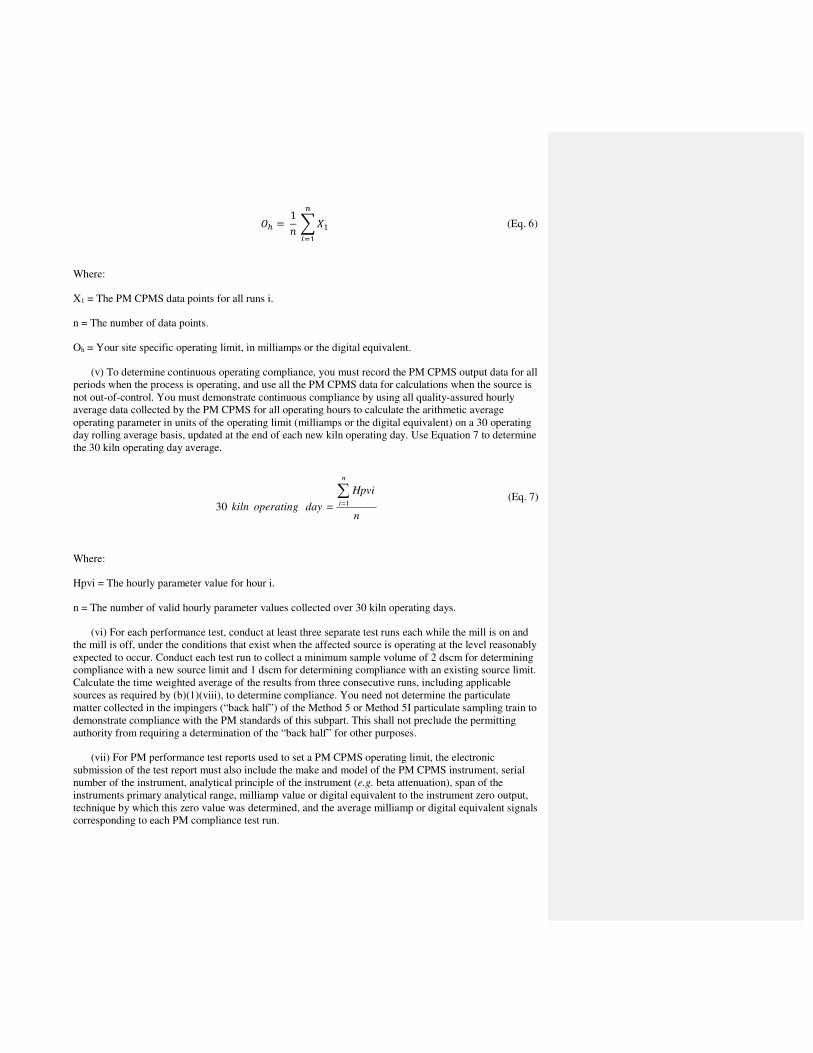
'* = 1�� ��
�
��� (Eq. 6)
Where:
X1 = The PM CPMS data points for all runs i.
n = The number of data points.
Oh = Your site specific operating limit, in milliamps or the digital equivalent.
(v) To determine continuous operating compliance, you must record the PM CPMS output data for all
periods when the process is operating, and use all the PM CPMS data for calculations when the source is
not out-of-control. You must demonstrate continuous compliance by using all quality-assured hourly
average data collected by the PM CPMS for all operating hours to calculate the arithmetic average
operating parameter in units of the operating limit (milliamps or the digital equivalent) on a 30 operating
day rolling average basis, updated at the end of each new kiln operating day. Use Equation 7 to determine
the 30 kiln operating day average.
n
Hpvi
dayoperatingkiln
n
i
∑=
=130
(Eq. 7)
Where:
Hpvi = The hourly parameter value for hour i.
n = The number of valid hourly parameter values collected over 30 kiln operating days.
(vi) For each performance test, conduct at least three separate test runs each while the mill is on and
the mill is off, under the conditions that exist when the affected source is operating at the level reasonably
expected to occur. Conduct each test run to collect a minimum sample volume of 2 dscm for determining
compliance with a new source limit and 1 dscm for determining compliance with an existing source limit.
Calculate the time weighted average of the results from three consecutive runs, including applicable
sources as required by (b)(1)(viii), to determine compliance. You need not determine the particulate
matter collected in the impingers (“back half”) of the Method 5 or Method 5I particulate sampling train to
demonstrate compliance with the PM standards of this subpart. This shall not preclude the permitting
authority from requiring a determination of the “back half” for other purposes.
(vii) For PM performance test reports used to set a PM CPMS operating limit, the electronic
submission of the test report must also include the make and model of the PM CPMS instrument, serial
number of the instrument, analytical principle of the instrument (e.g. beta attenuation), span of the
instruments primary analytical range, milliamp value or digital equivalent to the instrument zero output,
technique by which this zero value was determined, and the average milliamp or digital equivalent signals
corresponding to each PM compliance test run.

(viii) When there is an alkali bypass and/or an inline coal mill with a separate stack associated with a
kiln, the main exhaust and alkali bypass and/or inline coal mill must be tested simultaneously and the
combined emission rate of PM from the kiln and alkali bypass and/or inline coal mill must be computed
for each run using Equation 8 of this section.
+,� = +- + +. + +,� (Eq. 8)
Where:
ECm = Combined hourly emission rate of PM from the kiln and bypass stack and/or inline coal mill, lb/ton
of kiln clinker production.
EK = Hourly emissions of PM emissions from the kiln, lb.
EB = Hourly PM emissions from the alkali bypass stack, lb.
EC = Hourly PM emissions from the inline coal mill stack, lb.
P = Hourly clinker production, tons.
(ix) The owner or operator of a kiln with an in-line raw mill and subject to limitations on PM
emissions shall demonstrate initial compliance by conducting separate performance tests while the raw
mill is under normal operating conditions and while the raw mill is not operating, and calculate the time
weighted average emissions. The operating limit will then be determined using 63.1349(b)(1)(i) of this
section.
(3) D/F Emissions Tests. If you are subject to limitations on D/F emissions under this subpart, you
must conduct a performance test using Method 23 of appendix A-7 to part 60 of this chapter. If your kiln
or in-line kiln/raw mill is equipped with an alkali bypass, you must conduct simultaneous performance
tests of the kiln or in-line kiln/raw mill exhaust and the alkali bypass. You may conduct a performance
test of the alkali bypass exhaust when the raw mill of the in-line kiln/raw mill is operating or not
operating.
(i) Each performance test must consist of three separate runs conducted under representative
conditions. The duration of each run must be at least 3 hours, and the sample volume for each run must be
at least 2.5 dscm (90 dscf).
(ii) The temperature at the inlet to the kiln or in-line kiln/raw mill PMCD, and, where applicable, the
temperature at the inlet to the alkali bypass PMCD must be continuously recorded during the period of the
Method 23 test, and the continuous temperature record(s) must be included in the performance test report.
(iii) Average temperatures must be calculated for each run of the performance test.
(iv) The run average temperature must be calculated for each run, and the average of the run average
temperatures must be determined and included in the performance test report and will determine the
applicable temperature limit in accordance with §63.1346(b), footnote 2.
(v)(A) If sorbent injection is used for D/F control, you must record the rate of sorbent injection to the
kiln exhaust, and where applicable, the rate of sorbent injection to the alkali bypass exhaust, continuously

during the period of the Method 23 test in accordance with the conditions in §63.1350(m)(9), and include
the continuous injection rate record(s) in the performance test report. Determine the sorbent injection rate
parameters in accordance with paragraph (b)(3)(vi) of this section.
(B) Include the brand and type of sorbent used during the performance test in the performance test
report.
(C) Maintain a continuous record of either the carrier gas flow rate or the carrier gas pressure drop for
the duration of the performance test. If the carrier gas flow rate is used, determine, record, and maintain a
record of the accuracy of the carrier gas flow rate monitoring system according to the procedures in
appendix A to part 75 of this chapter. If the carrier gas pressure drop is used, determine, record, and
maintain a record of the accuracy of the carrier gas pressure drop monitoring system according to the
procedures in §63.1350(m)(6).
(vi) Calculate the run average sorbent injection rate for each run and determine and include the
average of the run average injection rates in the performance test report and determine the applicable
injection rate limit in accordance with §63.1346(c)(1).
(4) THC emissions test. (i) If you are subject to limitations on THC emissions, you must operate a
CEMS in accordance with the requirements in §63.1350(i). For the purposes of conducting the accuracy
and quality assurance evaluations for CEMS, the THC span value (as propane) is 50 ppmvw and the
reference method (RM) is Method 25A of appendix A to part 60 of this chapter.
(ii) Use the THC CEMS to conduct the initial compliance test for the first 30 kiln operating days of
kiln operation after the compliance date of the rule. See §63.1348(a).
(iii) If kiln gases are diverted through an alkali bypass or to a coal mill and exhausted through a
separate stack, you must calculate a kiln-specific THC limit using Equation 9:
/01 = 2�3/456768���9: + �;7 + �01�< − ��9:�/9:� − ��;7�/;7��01 (Eq. 9)
Where:
Cks = Kiln stack concentration (ppmvd).
Qab = Alkali bypass flow rate (volume/hr).
Cab = Alkali bypass concentration (ppmvd).
Qcm = Coal mill flow rate (volume/hr).
Ccm = Coal mill concentration (ppmvd).
Qks = Kiln stack flow rate (volume/hr).
(iv) THC must be measured either upstream of the coal mill or the coal mill stack.

(v) Instead of conducting the performance test specified in paragraph (b)(4)of this section, you may
conduct a performance test to determine emissions of total organic HAP by following the procedures in
paragraph (b)(7) of this section.
(5) Mercury Emissions Tests. If you are subject to limitations on mercury emissions, you must
operate a mercury CEMS or a sorbent trap monitoring system in accordance with the requirements of
§63.1350(k). The initial compliance test must be based on the first 30 kiln operating days in which the
affected source operates using a mercury CEMS or a sorbent trap monitoring system after the compliance
date of the rule. See §63.1348(a).
(i) If you are using a mercury CEMS or a sorbent trap monitoring system, you must install, operate,
calibrate, and maintain an instrument for continuously measuring and recording the exhaust gas flow rate
to the atmosphere according to the requirements in §63.1350(k)(5).
(ii) Calculate the emission rate using Equation 10 of this section:
P
CiQi
kE
n
iD
∑=
=1
30 (Eq. 10)
Where:
E30D = 30-day rolling emission rate of mercury, lb/MM tons clinker.
Ci = Concentration of mercury for operating hour i, µg/scm.
Qi = Volumetric flow rate of effluent gas for operating hour i, where Ci and Qi are on the same basis
(either wet or dry), scm/hr.
k = Conversion factor, 1 lb/454,000,000 µg.
n = Number of kiln operating hours in the previous 30 kiln operating day period where both C and Qi
qualified data are available.
P = Total runs from the previous 30 days of clinker production during the same time period as the
mercury emissions measured, million tons.
(7) Total Organic HAP Emissions Tests. Instead of conducting the performance test specified in
paragraph (b)(4) of this section, you may conduct a performance test to determine emissions of total
organic HAP by following the procedures in paragraphs (b)(7)(i) through (v) of this section.
(i) Use Method 320 of appendix A to this part, Method 18 of Appendix A of part 60, ASTM D6348-
03 or a combination to determine emissions of total organic HAP. Each performance test must consist of
three separate runs under the conditions that exist when the affected source is operating at the
representative performance conditions in accordance with §63.7(e). Each run must be conducted for at
least 1 hour.
(ii) At the same time that you are conducting the performance test for total organic HAP, you must
also determine a site-specific THC emissions limit by operating a THC CEMS in accordance with the

requirements of §63.1350(j). The duration of the performance test must be at least 3 hours and the
average THC concentration (as calculated from the recorded output) during the 3-hour test must be
calculated. You must establish your THC operating limit and determine compliance with it according to
paragraphs (b)(7)(vii) and (viii) of this section. It is permissible to extend the testing time of the organic
HAP performance test if you believe extended testing is required to adequately capture organic HAP
and/or THC variability over time.
(iii) If your source has an in-line kiln/raw mill you must use the fraction of time the raw mill is on and
the fraction of time that the raw mill is off and calculate this limit as a weighted average of the THC
levels measured during three raw mill on and three raw mill off tests.
(iv) If your organic HAP emissions are below 75 percent of the organic HAP standard and you
determine your operating limit with paragraph (b)(7)(vii) of this section your THC CEMS must be
calibrated and operated on a measurement scale no greater than 180 ppmvw, as carbon, or 60 ppmvw as
propane.
(v) If your kiln has an inline coal mill and/or an alkali bypass with separate stacks, you are required to
measure and account for oHAP emissions from their separate stacks. You are required to measure oHAP
at the coal mill inlet or outlet and you must also measure oHAP at the alkali bypass outlet. You must then
calculate a flow weighted average oHAP concentration for all emission sources including the inline coal
mill and the alkali bypass.
(vi) Your THC CEMS measurement scale must be capable of reading THC concentrations from zero
to a level equivalent to two times your highest THC emissions average determined during your
performance test, including mill on or mill off operation. Note: This may require the use of a dual range
instrument to meet this requirement and paragraph (b)(7)(iv) of this section.
(vii) Determine your operating limit as specified in paragraphs (b)(7)(viii) and (ix) of this section. If
your organic HAP performance test demonstrates your average organic HAP emission levels are below 75
percent of your emission limit (9 ppmv) you will use the average THC value recorded during the organic
HAP performance test, and the average total organic HAP result of your performance test to establish
your operating limit. If your organic HAP compliance test results demonstrate that your average organic
HAP emission levels are at or above 75 percent of your emission limit, your operating limit is established
as the average THC value recorded during the organic HAP performance test. You must establish a new
operating limit after each performance test. You must repeat the performance test no later than 30 months
following your last performance test and reassess and adjust the site-specific operating limit in accordance
with the results of the performance test.
(viii) If the average organic HAP results for your three Method 18 and/or Method 320 performance
test runs are below 75 percent of your organic HAP emission limit, you must calculate an operating limit
by establishing a relationship of THC CEMS signal to the organic HAP concentration using the average
THC CEMS value corresponding to the three organic HAP compliance test runs and the average organic
HAP total concentration from the Method 18 and/or Method 320 performance test runs with the
procedures in (b)(7)(viii)(A) and (B) of this section.
(A) Determine the THC CEMS average values in ppmvw, and the average of your corresponding
three total organic HAP compliance test runs, using Equation 12.
�̅ = 1� � ��
�
���, !" = 1
� � #��
��� (Eq. 12)

Where:
x̅ = The THC CEMS average values in ppmvw.
Xi = The THC CEMS data points for all three runs i.
Yi = The sum of organic HAP concentrations for test runs i. and
n = The number of data points.
(B) You must use your three run average THC CEMS value and your three run average organic HAP
concentration from your three Method 18 and/or Method 320 compliance tests to determine the operating
limit. Use equation 13 to determine your operating limit in units of ppmvw THC, as propane.
4= = > 9#�
@ ∗ �� (Eq. 13)
Where:
Tl = The 30-day operating limit for your THC CEMS, ppmvw.
Y1 = The average organic HAP concentration from Eq. 12, ppmvd.
X1 = The average THC CEMS concentration from Eq. 12, ppmvw.
(ix) If the average of your three organic HAP performance test runs is at or above 75 percent of your
organic HAP emission limit, you must determine your operating limit using Equation 14 by averaging the
THC CEMS output values corresponding to your three organic HAP performance test runs that
demonstrate compliance with the emission limit. If your new THC CEMS value is below your current
operating limit, you may opt to retain your current operating limit, but you must still submit all
performance test and THC CEMS data according to the reporting requirements in paragraph (d)(1) of this
section.
4* = 1�� ��
�
��� (Eq. 14)
Where:
X1 = The THC CEMS data points for all runs i.
n = The number of data points.
Th = Your site specific operating limit, in ppmvw THC.
(x) If your kiln has an inline kiln/raw mill, you must conduct separate performance tests while the raw
mill is operating (“mill on”) and while the raw mill is not operating (“mill off”). Using the fraction of

time the raw mill is on and the fraction of time that the raw mill is off, calculate this limit as a weighted
average of the THC levels measured during raw mill on and raw mill off compliance testing with
Equation 15.
$ = �! ∗ 8� + �� ∗ �1 − 8�� (Eq. 15)
Where:
R = Operating limit as THC, ppmvw.
y = Average THC CEMS value during mill on operations, ppmvw.
t = Percentage of operating time with mill on.
x = Average THC CEMS value during mill off operations, ppmvw.
(1-t) = Percentage of operating time with mill off.
(xi) To determine continuous compliance with the THC operating limit, you must record the THC
CEMS output data for all periods when the process is operating and the THC CEMS is not out-of-control.
You must demonstrate continuous compliance by using all quality-assured hourly average data collected
by the THC CEMS for all operating hours to calculate the arithmetic average operating parameter in units
of the operating limit (ppmvw) on a 30 operating day rolling average basis, updated at the end of each
new kiln operating day. Use Equation 16 to determine the 30 kiln operating day average.
n
Hpvi
dayoperatingkiln
n
i
∑=
=130
(Eq. 16)
Where:
Hpvi = The hourly parameter value for hour i, ppmvw.
n = The number of valid hourly parameter values collected over 30 kiln operating days.
(xii) Use EPA Method 18 or Method 320 of appendix A to part 60 of this chapter to determine
organic HAP emissions. For each performance test, conduct at least three separate runs under the
conditions that exist when the affected source is operating at the level reasonably expected to occur. If
your source has an in-line kiln/raw mill you must conduct three separate test runs with the raw mill on,
and three separate runs under the conditions that exist when the affected source is operating at the level
reasonably expected to occur with the mill off. Conduct each Method 18 test run to collect a minimum
target sample equivalent to three times the method detection limit. Calculate the average of the results
from three runs to determine compliance.
(xiii) If the THC level exceeds by 10 percent or more your site-specific THC emissions limit, you
must

(A) As soon as possible but no later than 30 days after the exceedance, conduct an inspection and take
corrective action to return the THC CEMS measurements to within the established value; and
(B) Within 90 days of the exceedance or at the time of the 30 month compliance test, whichever
comes first, conduct another performance test to determine compliance with the organic HAP limit and to
verify or re-establish your site-specific THC emissions limit.
Performance Testing Requirements – Pollutant Specific Requirements for HCl: 63.1349(b)(6), (8)
§63.1349 Performance testing requirements.
(6) HCl emissions tests. For a source subject to limitations on HCl emissions you must conduct
performance testing by one of the following methods:
(i)(A) If the source is equipped with a wet scrubber, tray tower or dry scrubber, you must conduct
performance testing using Method 321 of appendix A to this part unless you have installed a CEMS that
meets the requirements §63.1350(l)(1). For kilns with inline raw mills, testing should be conducted for
the raw mill on and raw mill off conditions.
(B) You must establish site specific parameter limits by using the CPMS required in §63.1350(l)(1).
For a wet scrubber or tray tower, measure and record the pressure drop across the scrubber and/or liquid
flow rate and pH in intervals of no more than 15 minutes during the HCl test. Compute and record the 24-
hour average pressure drop, pH, and average scrubber water flow rate for each sampling run in which the
applicable emissions limit is met. For a dry scrubber, measure and record the sorbent injection rate in
intervals of no more than 15 minutes during the HCl test. Compute and record the 24-hour average
sorbent injection rate and average sorbent injection rate for each sampling run in which the applicable
emissions limit is met.
(ii)(A) If the source is not controlled by a wet scrubber, tray tower or dry sorbent injection system,
you must operate a CEMS in accordance with the requirements of §63.1350(l)(1). See §63.1348(a).
(B) The initial compliance test must be based on the 30 kiln operating days that occur after the
compliance date of this rule in which the affected source operates using an HCl CEMS. Hourly HCl
concentration data must be obtained according to §63.1350(l).
(iii) As an alternative to paragraph (b)(6)(i)(B) of this section, you may choose to monitor SO2
emissions using a CEMS in accordance with the requirements of §63.1350(l)(3). You must establish an
SO2 operating limit equal to the average recorded during the HCl stack test where the HCl stack test run
result demonstrates compliance with the emission limit. This operating limit will apply only for
demonstrating HCl compliance.
(iv) If kiln gases are diverted through an alkali bypass or to a coal mill and exhausted through a
separate stack, you must calculate a kiln-specific HCl limit using Equation 11:
/01 = 2�3/4)6768���9: + �;7 + �01�< − ��9:�/9:� − ��;7�/;7��01 (Eq. 11)
Where:

Cks = Kiln stack concentration (ppmvd).
Qab = Alkali bypass flow rate (volume/hr).
Cab = Alkali bypass concentration (ppmvd).
Qcm = Coal mill flow rate (volume/hr).
Ccm = Coal mill concentration (ppmvd).
Qks = Kiln stack flow rate (volume/hr).
(8) HCl Emissions Tests with SO2 Monitoring. If you choose to monitor SO2 emissions using a CEMS
to demonstrate HCl compliance, follow the procedures in (b)(8)(i) through (ix) of this section and in
accordance with the requirements of §63.1350(l)(3). You must establish an SO2 operating limit equal to
the average recorded during the HCl stack test. This operating limit will apply only for demonstrating
HCl compliance.
(i) Use Method 321 of appendix A to this part to determine emissions of HCl. Each performance test
must consist of three separate runs under the conditions that exist when the affected source is operating at
the representative performance conditions in accordance with §63.7(e). Each run must be conducted for at
least one hour.
(ii) At the same time that you are conducting the performance test for HCl, you must also determine a
site-specific SO2 emissions limit by operating an SO2 CEMS in accordance with the requirements of
§63.1350(l). The duration of the performance test must be three hours and the average SO2 concentration
(as calculated from the average output) during the 3-hour test must be calculated. You must establish your
SO2 operating limit and determine compliance with it according to paragraphs (b)(8)(vii) and (viii) of this
section.
(iii) If your source has an in-line kiln/raw mill you must use the fraction of time the raw mill is on and
the fraction of time that the raw mill is off and calculate this limit as a weighted average of the SO2 levels
measured during raw mill on and raw mill off testing.
(iv) Your SO2 CEMS must be calibrated and operated according to the requirements of §60.63(f).
(v) Your SO2 CEMS measurement scale must be capable of reading SO2 concentrations consistent
with the requirements of §60.63(f), including mill on or mill off operation.
(vi) If your kiln has an inline kiln/raw mill, you must conduct separate performance tests while the
raw mill is operating (“mill on”) and while the raw mill is not operating (“mill off”). Using the fraction of
time the raw mill is on and the fraction of time that the raw mill is off, calculate this limit as a weighted
average of the HCl levels measured during raw mill on and raw mill off compliance testing with Equation
17.
$ = �! ∗ 8� + � ∗ �8 − 1� (Eq. 17)
Where:
R = Operating limit as SO2, ppmvw.
Commented [LMN1]: In the rule, the equation contains (t-
1), but I think it should be (1-t).
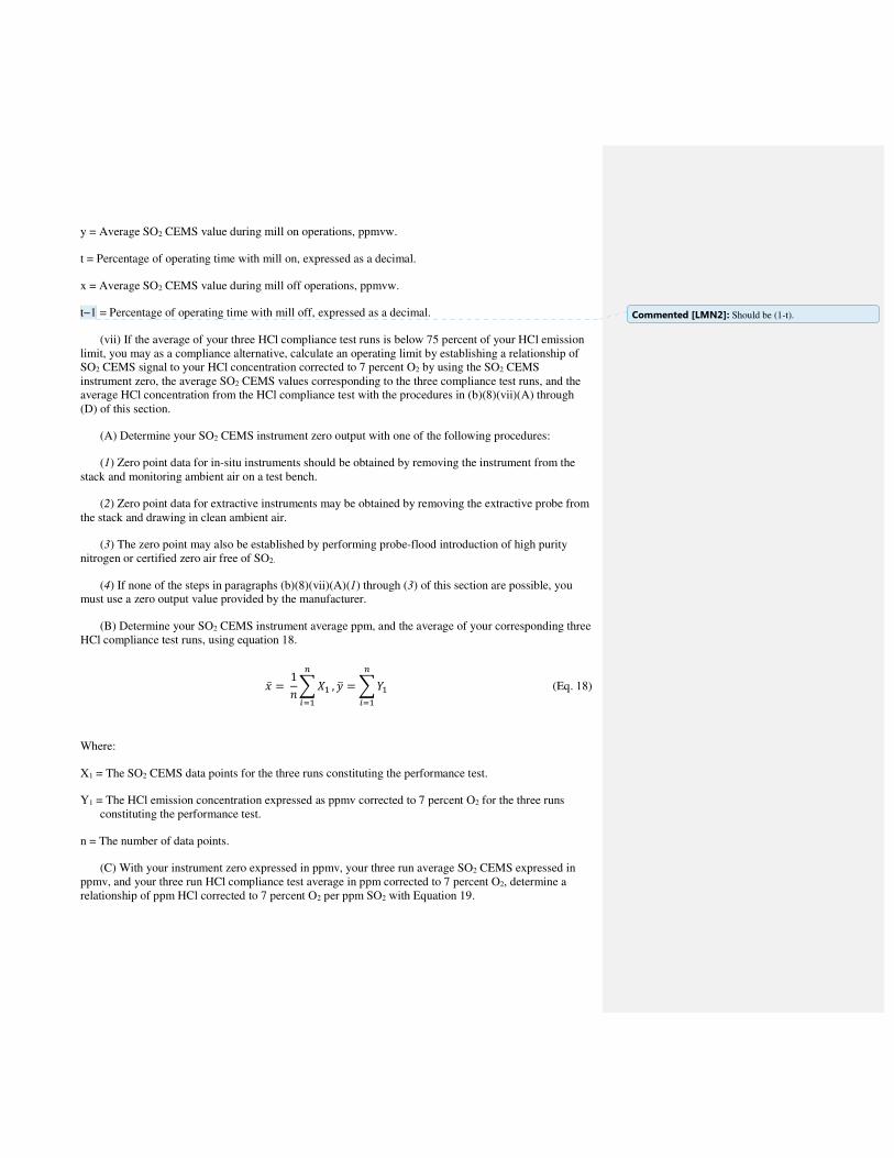
y = Average SO2 CEMS value during mill on operations, ppmvw.
t = Percentage of operating time with mill on, expressed as a decimal.
x = Average SO2 CEMS value during mill off operations, ppmvw.
t−1 = Percentage of operating time with mill off, expressed as a decimal.
(vii) If the average of your three HCl compliance test runs is below 75 percent of your HCl emission
limit, you may as a compliance alternative, calculate an operating limit by establishing a relationship of
SO2 CEMS signal to your HCl concentration corrected to 7 percent O2 by using the SO2 CEMS
instrument zero, the average SO2 CEMS values corresponding to the three compliance test runs, and the
average HCl concentration from the HCl compliance test with the procedures in (b)(8)(vii)(A) through
(D) of this section.
(A) Determine your SO2 CEMS instrument zero output with one of the following procedures:
(1) Zero point data for in-situ instruments should be obtained by removing the instrument from the
stack and monitoring ambient air on a test bench.
(2) Zero point data for extractive instruments may be obtained by removing the extractive probe from
the stack and drawing in clean ambient air.
(3) The zero point may also be established by performing probe-flood introduction of high purity
nitrogen or certified zero air free of SO2.
(4) If none of the steps in paragraphs (b)(8)(vii)(A)(1) through (3) of this section are possible, you
must use a zero output value provided by the manufacturer.
(B) Determine your SO2 CEMS instrument average ppm, and the average of your corresponding three
HCl compliance test runs, using equation 18.
�̅ = 1� � ��
�
���, !" = � #�
�
��� (Eq. 18)
Where:
X1 = The SO2 CEMS data points for the three runs constituting the performance test.
Y1 = The HCl emission concentration expressed as ppmv corrected to 7 percent O2 for the three runs
constituting the performance test.
n = The number of data points.
(C) With your instrument zero expressed in ppmv, your three run average SO2 CEMS expressed in
ppmv, and your three run HCl compliance test average in ppm corrected to 7 percent O2, determine a
relationship of ppm HCl corrected to 7 percent O2 per ppm SO2 with Equation 19.
Commented [LMN2]: Should be (1-t).

$ = #���� − &� (Eq. 19)
Where:
R = The relative HCl ppmv corrected to 7 percent O2 per ppm SO2 for your SO2 CEMS.
Y1 = The three run average HCl concentration corrected to 7 percent O2.
X1 = The three run average ppm recorded by your SO2 CEMS.
z = The instrument zero output ppm value.
(D) Determine your source specific 30-day rolling average operating limit using ppm HCl corrected
to 7 percent O2 per ppm SO2 value from Equation 19 in Equation 20, below. This sets your operating limit
at the SO2 CEMS ppm value corresponding to 75 percent of your emission limit.
'� = & + 0.75�)�$ (Eq. 20)
Where:
Ol = The operating limit for your SO2 CEMS on a 30-day rolling average, in ppmv.
L = Your source HCl emission limit expressed in ppmv corrected to 7 percent O2.
z = Your instrument zero in ppmv, determined from (1)(i).
R = The relative oxygen corrected ppmv HCl per ppmv SO2, for your SO2 CEMS, from Equation 19.
(viii) To determine continuous compliance with the SO2 operating limit, you must record the SO2
CEMS output data for all periods when the process is operating and the SO2 CEMS is not out-of-control.
You must demonstrate continuous compliance by using all quality-assured hourly average data collected
by the SO2 CEMS for all operating hours to calculate the arithmetic average operating parameter in units
of the operating limit (ppmvw) on a 30 operating day rolling average basis, updated at the end of each
new kiln operating day. Use Equation 21 to determine the 30 kiln operating day average.
n
Hpvi
dayoperatingkiln
n
i
∑=
=130
(Eq. 21)
Where:
Hpvi = The hourly parameter value for hour i, ppmvw.

n = The number of valid hourly parameter values collected over 30 kiln operating days.
(ix) Use EPA Method 321 of appendix A to part 60 of this chapter to determine HCl emissions. For
each performance test, conduct at least three separate runs under the conditions that exist when the
affected source is operating at the level reasonably expected to occur. If your source has an in-line
kiln/raw mill you must conduct three separate test runs with the raw mill on, and three separate runs under
the conditions that exist when the affected source is operating at the level reasonably expected to occur
with the mill off.
(x) If the SO2 level exceeds by 10 percent or more your site-specific SO2 emissions limit, you must:
(A) As soon as possible but no later than 30 days after the exceedance, conduct an inspection and take
corrective action to return the SO2 CEMS measurements to within the established value;
(B) Within 90 days of the exceedance or at the time of the periodic compliance test, whichever comes
first, conduct another performance test to determine compliance with the HCl limit and to verify or re-
establish your site-specific SO2 emissions limit.
Performance Testing Requirements – Frequency: 63.1349(c)
§63.1349 Performance testing requirements.
(c) Performance test frequency. Except as provided in §63.1348(b), performance tests are required at
regular intervals for affected sources that are subject to a dioxin, organic HAP or HCl emissions limit.
Performance tests required every 30 months must be completed no more than 31 calendar months after
the previous performance test except where that specific pollutant is monitored using CEMS;
performance tests required every 12 months must be completed no more than 13 calendar months after the
previous performance test.
Monitoring – PM: 63.1350(b)
§63.1350 Monitoring requirements.
(b) PM monitoring requirements. (1)(i) PM CPMS. You will use a PM CPMS to establish a site-
specific operating limit corresponding to the results of the performance test demonstrating compliance
with the PM limit. You will conduct your performance test using Method 5 or Method 5I at appendix A-3
to part 60 of this chapter. You will use the PM CPMS to demonstrate continuous compliance with this
operating limit. You must repeat the performance test annually and reassess and adjust the site-specific
operating limit in accordance with the results of the performance test using the procedures in
§63.1349(b)(1) (i) through (vi) of this subpart. You must also repeat the test if you change the analytical
range of the instrument, or if you replace the instrument itself or any principle analytical component of
the instrument that would alter the relationship of output signal to in-stack PM concentration.
(ii) To determine continuous compliance, you must use the PM CPMS output data for all periods
when the process is operating and the PM CPMS is not out-of-control. You must demonstrate continuous
compliance by using all quality-assured hourly average data collected by the PM CPMS for all operating
hours to calculate the arithmetic average operating parameter in units of the operating limit (milliamps)
on a 30 operating day rolling average basis, updated at the end of each new kiln operating day.
(iii) For any exceedance of the 30 process operating day PM CPMS average value from the
established operating parameter limit, you must:

(A) Within 48 hours of the exceedance, visually inspect the APCD;
(B) If inspection of the APCD identifies the cause of the exceedance, take corrective action as soon as
possible and return the PM CPMS measurement to within the established value; and
(C) Within 30 days of the exceedance or at the time of the annual compliance test, whichever comes
first, conduct a PM emissions compliance test to determine compliance with the PM emissions limit and
to verify or re-establish the PM CPMS operating limit within 45 days. You are not required to conduct
additional testing for any exceedances that occur between the time of the original exceedance and the PM
emissions compliance test required under this paragraph.
(iv) PM CPMS exceedances leading to more than four required performance tests in a 12-month
process operating period (rolling monthly) constitute a presumptive violation of this subpart.
(2) [Reserved]
Monitoring – D/F: 63.1350(g)
§63.1350 Monitoring requirements.
(g) D/F monitoring requirements. If you are subject to an emissions limitation on D/F emissions, you
must comply with the monitoring requirements of paragraphs (g)(1) through (g)(6) and paragraphs (m)(1)
through (m)(4) of this section to demonstrate continuous compliance with the D/F emissions standard.
You must also develop an emissions monitoring plan in accordance with paragraphs (p)(1) through (p)(4)
of this section.
(1) You must install, calibrate, maintain, and continuously operate a CMS to record the temperature
of the exhaust gases from the kiln and alkali bypass, if applicable, at the inlet to, or upstream of, the kiln
and/or alkali bypass PMCDs.
(i) The temperature recorder response range must include zero and 1.5 times the average temperature
established according to the requirements in §63.1349(b)(3)(iv).
(ii) The calibration reference for the temperature measurement must be a National Institute of
Standards and Technology calibrated reference thermocouple-potentiometer system or alternate reference,
subject to approval by the Administrator.
(iii) The calibration of all thermocouples and other temperature sensors must be verified at least once
every three months.
(2) You must monitor and continuously record the temperature of the exhaust gases from the kiln and
alkali bypass, if applicable, at the inlet to the kiln and/or alkali bypass PMCD.
(3) The required minimum data collection frequency must be one minute.
(4) Calculate the rolling three-hour average temperature using the average of 180 successive one-
minute average temperatures. See §63.1349(b)(3).
(5) When the operating status of the raw mill of the in-line kiln/raw mill is changed from off to on or
from on to off, the calculation of the three-hour rolling average temperature must begin anew, without
considering previous recordings.

Monitoring – Sorbent Injection: 63.1350(h)
§63.1350 Monitoring requirements.
(h) Monitoring requirements for sources using sorbent injection. If you are subject to an operating
limit on D/F emissions that employs carbon injection as an emission control technique, you must comply
with the additional monitoring requirements of paragraphs (h)(1) and (h)(2) and paragraphs (m)(1)
through (m)(4) and (m)(9) of this section. You must also develop an emissions monitoring plan in
accordance with paragraphs (p)(1) through (p)(4) of this section.
(1) Install, operate, calibrate, and maintain a continuous monitor to record the rate of activated carbon
injection. The accuracy of the rate measurement device must be ±1 percent of the rate being measured.
(i) Verify the calibration of the device at least once every three months.
(ii) Each hour, calculate the three-hour rolling average activated carbon injection rate for the previous
three hours of process operation. See §63.1349(b)(3).
(iii) When the operating status of the raw mill of the in-line kiln/raw mill is changed from off to on or
from on to off, the calculation of the three-hour rolling average activated carbon injection rate must begin
anew, without considering previous recordings.
(2)(i) Install, operate, calibrate, and maintain a continuous monitor to record the activated carbon
injection system carrier gas parameter (either the carrier gas flow rate or the carrier gas pressure drop)
established during the D/F performance test in accordance with §63.1349(b)(3).
(ii) Each hour, calculate the three-hour rolling average of the selected parameter value for the
previous 3 hours of process operation using all of the one-minute data available (i.e., the CMS is not out-
of-control.)
Monitoring – THC: 63.1350(i)
§63.1350 Monitoring requirements.
(i) THC Monitoring Requirements. If you are subject to an emissions limitation on THC emissions,
you must comply with the monitoring requirements of paragraphs (i)(1) and (i)(2) and (m)(1) through
(m)(4) of this section. You must also develop an emissions monitoring plan in accordance with
paragraphs (p)(1) through (p)(4) of this section.
(1) You must install, operate, and maintain a THC continuous emission monitoring system in
accordance with Performance Specification 8 or Performance Specification 8A of appendix B to part 60
of this chapter and comply with all of the requirements for continuous monitoring systems found in the
general provisions, subpart A of this part. The owner or operator must operate and maintain each CEMS
according to the quality assurance requirements in Procedure 1 of appendix F in part 60 of this chapter.
For THC continuous emission monitoring systems certified under Performance Specification 8A, conduct
the relative accuracy test audits required under Procedure 1 in accordance with Performance Specification
8, Sections 8 and 11 using Method 25A in appendix A to 40 CFR part 60 as the reference method; the
relative accuracy must meet the criteria of Performance Specification 8, Section 13.2.
(2) Performance tests on alkali bypass and coal mill stacks must be conducted using Method 25A in
appendix A to 40 CFR part 60 and repeated every 30 months.

Monitoring – Total Organic HAP: 63.1350(j)
§63.1350 Monitoring requirements.
(j) Total organic HAP monitoring requirements. If you are complying with the total organic HAP
emissions limits, you must continuously monitor THC according to paragraph (i)(1) and (2) of this
section or in accordance with Performance Specification 8 or Performance Specification 8A of appendix
B to part 60 of this chapter and comply with all of the requirements for continuous monitoring systems
found in the general provisions, subpart A of this part. You must operate and maintain each CEMS
according to the quality assurance requirements in Procedure 1 of appendix F in part 60 of this chapter. In
addition, your must follow the monitoring requirements in paragraphs (m)(1) through (4) of this section.
You must also develop an emissions monitoring plan in accordance with paragraphs (p)(1) through (4) of
this section.
Monitoring – Mercury: 63.1350(k)
§63.1350 Monitoring requirements.
(k) Mercury monitoring requirements. If you have a kiln subject to an emissions limitation on
mercury emissions, you must install and operate a mercury continuous emissions monitoring system (Hg
CEMS) in accordance with Performance Specification 12A (PS 12A) of appendix B to part 60 of this
chapter or an integrated sorbent trap monitoring system in accordance with Performance Specification
12B (PS 12B) of appendix B to part 60 of this chapter. You must monitor mercury continuously
according to paragraphs (k)(1) through (5) of this section. You must also develop an emissions
monitoring plan in accordance with paragraphs (p)(1) through (4) of this section.
(1) You must use a span value for any Hg CEMS that represents the mercury concentration
corresponding to approximately two times the emissions standard and may be rounded up to the nearest
multiple of 5 µg/m3 of total mercury or higher level if necessary to include Hg concentrations which may
occur (excluding concentrations during in-line raw “mill off” operation). As specified in PS 12A, Section
6.1.1, the data recorder output range must include the full range of expected Hg concentration values
which would include those expected during “mill off” conditions. Engineering judgments made and
calculations used to determine the corresponding span concentration from the emission standard shall be
documented in the site-specific monitoring plan and associated records.
(2) In order to quality assure data measured above the span value, you must use one of the three
options in paragraphs (k)(2)(i) through (iii) of this section. Where the options in paragraphs (k)(2)(i)
through (iii) are employed while the kiln is operating in a mill-off mode, the “above span” described in
paragraph (k)(2)(iii) may substitute for the daily upscale calibration provided the data normalization
process in paragraph (k)(2)(iii) are not required. If data normalization is required, the normal daily
upscale calibration check must be performed to quality assure the operation of the CEMS for that day. In
this particular case, adjustments to CEMS normally required by Procedure 5 when a daily upscale does
not meet the 5 percent criterion are not required, unless paragraph (k)(2)(iii) of this section data
normalization is necessary and a subsequent normal daily calibration check demonstrates the need for
such adjustment.
(i) Include a second span that encompasses the Hg emission concentrations expected to be
encountered during “mill off” conditions. This second span may be rounded to a multiple of 5 µg/m3 of
total mercury. The requirements of PS 12A, shall be followed for this second span with the exception that
a RATA with the mill off is not required.

(ii) Quality assure any data above the span value by proving instrument linearity beyond the span
value established in paragraph (k)(1) of this section using the following procedure. Conduct a weekly
“above span linearity” calibration challenge of the monitoring system using a reference gas with a
certified value greater than your highest expected hourly concentration or greater than 75 percent of the
highest measured hourly concentration. The “above span” reference gas must meet the requirements of PS
12A, Section 7.1 and must be introduced to the measurement system at the probe. Record and report the
results of this procedure as you would for a daily calibration. The “above span linearity” challenge is
successful if the value measured by the Hg CEMS falls within 10 percent of the certified value of the
reference gas. If the value measured by the Hg CEMS during the above span linearity challenge exceeds
±10 percent of the certified value of the reference gas, the monitoring system must be evaluated and
repaired and a new “above span linearity” challenge met before returning the Hg CEMS to service, or
data above span from the Hg CEMS must be subject to the quality assurance procedures established in
paragraph (k)(2)(iii) of this section. In this manner all hourly average values exceeding the span value
measured by the Hg CEMS during the week following the above span linearity challenge when the
CEMS response exceeds ±20 percent of the certified value of the reference gas must be normalized using
Equation 22.
/BC86D6BECBDBCB�;BF91G95HB�B91HCBEG95HBIDCBDBCB�;BF91 ��B91HCBE189;0F91CB1H58
= JIC7956&BE189;0F91CB1H58 (Eq. 22)
(iii) Quality assure any data above the span value established in paragraph (k)(1) of this section using
the following procedure. Any time two consecutive one-hour average measured concentrations of Hg
exceeds the span value you must, within 24 hours before or after, introduce a higher, “above span” Hg
reference gas standard to the Hg CEMS. The “above span” reference gas must meet the requirements of
PS 12A, Section 7.1, must target a concentration level between 50 and 150 percent of the highest
expected hourly concentration measured during the period of measurements above span, and must be
introduced at the probe. While this target represents a desired concentration range that is not always
achievable in practice, it is expected that the intent to meet this range is demonstrated by the value of the
reference gas. Expected values may include “above span” calibrations done before or after the above span
measurement period. Record and report the results of this procedure as you would for a daily calibration.
The “above span” calibration is successful if the value measured by the Hg CEMS is within 20 percent of
the certified value of the reference gas. If the value measured by the Hg CEMS exceeds 20 percent of the
certified value of the reference gas, then you must normalize the one-hour average stack gas values
measured above the span during the 24-hour period preceding or following the “above span” calibration
for reporting based on the Hg CEMS response to the reference gas as shown in equation 22 below. Only
one “above span” calibration is needed per 24 hour period.
(3) You must operate and maintain each Hg CEMS or an integrated sorbent trap monitoring system
according to the quality assurance requirements in Procedure 5 of appendix F to part 60 of this chapter.
During the RATA of integrated sorbent trap monitoring systems required under Procedure 5, you may
apply the appropriate exception for sorbent trap section 2 breakthrough in (k)(3)(i) through (iv) of this
section:
(i) For stack Hg concentrations >1 µg/dscm, ≤10% of section 1 mass;
(ii) For stack Hg concentrations ≤1 µg/dscm and >0.5 µg/dscm, ≤20% of section 1 mass;

(iii) For stack Hg concentrations ≤0.5 µg/dscm and >0.1 µg/dscm, ≤50% of section 1 mass; and
(iv) For stack Hg concentrations ≤0.1 µg/dscm, no breakthrough criterion assuming all other QA/QC
specifications are met.
(4) Relative accuracy testing of mercury monitoring systems under PS 12A, PS 12B, or Procedure 5
must be conducted at normal operating conditions. If a facility has an inline raw mill, the testing must
occur with the raw mill on.
(5) If you use a Hg CEMS or an integrated sorbent trap monitoring system, you must install, operate,
calibrate, and maintain an instrument for continuously measuring and recording the exhaust gas flow rate
to the atmosphere according to the requirements in paragraphs (n)(1) through (10) of this section. If kiln
gases are diverted through an alkali bypass or to a coal mill and exhausted through separate stacks, you
must account for the mercury emitted from those stacks by following the procedures in (k)(5)(i) through
(iv) of this section:
(i) Develop a mercury hourly mass emissions rate by conducting performance tests annually, within
11 to 13 calendar months after the previous performance test, using Method 29, or Method 30B, to
measure the concentration of mercury in the gases exhausted from the alkali bypass and coal mill.
(ii) On a continuous basis, determine the mass emissions of mercury in lb/hr from the alkali bypass
and coal mill exhausts by using the mercury hourly emissions rate, the exhaust gas flow rate and hourly
mercury emission rate to calculate hourly mercury emissions in lb/hr.
(iii) Sum the hourly mercury emissions from the kiln, alkali bypass and coal mill to determine total
mercury emissions. Using hourly clinker production, calculate the hourly emissions rate in pounds per ton
of clinker to determine your 30 day rolling average.
(iv) If mercury emissions from the coal mill and alkali bypass are below the method detection limit
for two consecutive annual performance tests, you may reduce the frequency of the performance tests of
coal mills and alkali bypasses to once every 30 months. If the measured mercury concentration exceeds
the method detection limit, you must revert to testing annually until two consecutive annual tests are
below the method detection limit.
(6) If you operate an integrated sorbent trap monitoring system conforming to PS 12B, you may use a
monitoring period at least 24 hours but no longer than 168 hours in length. You should use a monitoring
period that is a multiple of 24 hours (except during relative accuracy testing as allowed in PS 12B).
Monitoring – HCl: 63.1350(l)
§63.1350 Monitoring requirements.
(l) HCl Monitoring Requirements. If you are subject to an emissions limitation on HCl emissions in
§63.1343, you must monitor HCl emissions continuously according to paragraph (l)(1) or (2) and
paragraphs (m)(1) through (4) of this section or, if your kiln is controlled using a wet or dry scrubber or
tray tower, you alternatively may parametrically monitor SO2 emissions continuously according to
paragraph (l)(3) of this section. You must also develop an emissions monitoring plan in accordance with
paragraphs (p)(1) through (4) of this section.
(1) If you monitor compliance with the HCl emissions limit by operating an HCl CEMS, you must do
so in accordance with Performance Specification 15 (PS 15) of appendix B to part 60 of this chapter, or,

upon promulgation, in accordance with any other performance specification for HCl CEMS in appendix B
to part 60 of this chapter. You must operate, maintain, and quality assure a HCl CEMS installed and
certified under PS 15 according to the quality assurance requirements in Procedure 1 of appendix F to part
60 of this chapter except that the Relative Accuracy Test Audit requirements of Procedure 1 must be
replaced with the validation requirements and criteria of sections 11.1.1 and 12.0 of PS 15. When
promulgated, if you choose to install and operate an HCl CEMS in accordance with PS 18 of appendix B
to part 60 of this chapter, you must operate, maintain and quality assure the HCl CEMS using the
associated Procedure 6 of appendix F to part 60 of this chapter. For any performance specification that
you use, you must use Method 321 of appendix A to part 63 of this chapter as the reference test method
for conducting relative accuracy testing. The span value and calibration requirements in paragraphs
(l)(1)(i) and (ii) of this section apply to HCl CEMS other than those installed and certified under PS 15.
(i) You must use a measurement span value for any HCl CEMS of 0-10 ppmvw unless the monitor is
installed on a kiln without an inline raw mill. Kilns without an inline raw mill may use a higher span
value sufficient to quantify all expected emissions concentrations. The HCl CEMS data recorder output
range must include the full range of expected HCl concentration values which would include those
expected during “mill off” conditions. The corresponding data recorder range shall be documented in the
site-specific monitoring plan and associated records.
(ii) In order to quality assure data measured above the span value, you must use one of the three
options in paragraphs (l)(1)(ii)(A) through (C) of this section.
(A) Include a second span that encompasses the HCl emission concentrations expected to be
encountered during “mill off” conditions. This second span may be rounded to a multiple of 5 ppm of
total HCl. The requirements of the appropriate HCl monitor performance specification shall be followed
for this second span with the exception that a RATA with the mill off is not required.
(B) Quality assure any data above the span value by proving instrument linearity beyond the span
value established in paragraph (l)(1)(i) of this section using the following procedure. Conduct a weekly
“above span linearity” calibration challenge of the monitoring system using a reference gas with a
certified value greater than your highest expected hourly concentration or greater than 75 percent of the
highest measured hourly concentration. The “above span” reference gas must meet the requirements of
the applicable performance specification and must be introduced to the measurement system at the probe.
Record and report the results of this procedure as you would for a daily calibration. The “above span
linearity” challenge is successful if the value measured by the HCl CEMS falls within 10 percent of the
certified value of the reference gas. If the value measured by the HCl CEMS during the above span
linearity challenge exceeds 10 percent of the certified value of the reference gas, the monitoring system
must be evaluated and repaired and a new “above span linearity” challenge met before returning the HCl
CEMS to service, or data above span from the HCl CEMS must be subject to the quality assurance
procedures established in paragraph (l)(1)(ii)(D) of this section. Any HCl CEMS above span linearity
challenge response exceeding ±20 percent of the certified value of the reference gas requires that all
above span hourly averages during the week following the above span linearity challenge must be
normalized using Equation 23.
(C) Quality assure any data above the span value established in paragraph (l)(1)(i) of this section
using the following procedure. Any time two consecutive one-hour average measured concentration of
HCl exceeds the span value you must, within 24 hours before or after, introduce a higher, “above span”
HCl reference gas standard to the HCl CEMS. The “above span” reference gas must meet the
requirements of the applicable performance specification and target a concentration level between 50 and
150 percent of the highest expected hourly concentration measured during the period of measurements
above span, and must be introduced at the probe. While this target represents a desired concentration

range that is not always achievable in practice, it is expected that the intent to meet this range is
demonstrated by the value of the reference gas. Expected values may include above span calibrations
done before or after the above-span measurement period. Record and report the results of this procedure
as you would for a daily calibration. The “above span” calibration is successful if the value measured by
the HCl CEMS is within 20 percent of the certified value of the reference gas. If the value measured by
the HCl CEMS is not within 20 percent of the certified value of the reference gas, then you must
normalize the stack gas values measured above span as described in paragraph (l)(1)(ii)(D) of this section.
(D) In the event that the “above span” calibration is not successful (i.e., the HCl CEMS measured
value is not within 20 percent of the certified value of the reference gas), then you must normalize the
one-hour average stack gas values measured above the span during the 24-hour period preceding or
following the `above span' calibration for reporting based on the HCl CEMS response to the reference gas
as shown in Equation 23:
/BC86D6BECBDBCB�;BF91G95HB�B91HCBEG95HBIDCBDBCB�;BF91 ��B91HCBE189;0F91CB1H58
= JIC7956&BE189;0F91CB1H58 (Eq. 23)
Only one “above span” calibration is needed per 24-hour period.
(2) Install, operate, and maintain a CMS to monitor wet scrubber or tray tower parameters, as
specified in paragraphs (m)(5) and (7) of this section, and dry scrubber, as specified in paragraph (m)(9)
of this section.
(3) If the source is equipped with a wet or dry scrubber or tray tower, and you choose to monitor SO2
emissions, monitor SO2 emissions continuously according to the requirements of §60.63(e) and (f) of part
60 subpart F of this chapter. If SO2 levels increase above the 30-day rolling average SO2 operating limit
established during your performance test, you must:
(i) As soon as possible but no later than 48 hours after you exceed the established SO2 value conduct
an inspection and take corrective action to return the SO2 emissions to within the operating limit; and
(ii) Within 60 days of the exceedance or at the time of the next compliance test, whichever comes
first, conduct an HCl emissions compliance test to determine compliance with the HCl emissions limit
and to verify or re-establish the SO2 CEMS operating limit.
Monitoring – Parameter Monitoring: 63.1350(m), (m)(1) - (9)
§63.1350 Monitoring requirements.
(m) Parameter monitoring requirements. If you have an operating limit that requires the use of a
CMS, you must install, operate, and maintain each continuous parameter monitoring system (CPMS)
according to the procedures in paragraphs (m)(1) through (4) of this section by the compliance date
specified in §63.1351. You must also meet the applicable specific parameter monitoring requirements in
paragraphs (m)(5) through (11) that are applicable to you.
(1) The CMS must complete a minimum of one cycle of operation for each successive 15-minute
period. You must have a minimum of four successive cycles of operation to have a valid hour of data.

(2) You must conduct all monitoring in continuous operation at all times that the unit is operating.
(3) Determine the 1-hour block average of all recorded readings.
(4) Record the results of each inspection, calibration, and validation check.
(5) Liquid flow rate monitoring requirements. If you have an operating limit that requires the use of a
flow measurement device, you must meet the requirements in paragraphs (m)(5)(i) through (iv) of this
section.
(i) Locate the flow sensor and other necessary equipment in a position that provides a representative
flow.
(ii) Use a flow sensor with a measurement sensitivity of 2 percent of the flow rate.
(iii) Reduce swirling flow or abnormal velocity distributions due to upstream and downstream
disturbances.
(iv) Conduct a flow sensor calibration check at least semiannually.
(6) Specific pressure monitoring requirements. If you have an operating limit that requires the use of
a pressure measurement device, you must meet the requirements in paragraphs (m)(6)(i) through (vi) of
this section.
(i) Locate the pressure sensor(s) in a position that provides a representative measurement of the
pressure.
(ii) Minimize or eliminate pulsating pressure, vibration, and internal and external corrosion.
(iii) Use a gauge with a minimum tolerance of 1.27 centimeters of water or a transducer with a
minimum tolerance of 1 percent of the pressure range.
(iv) Check pressure tap pluggage daily.
(v) Using a manometer, check gauge calibration quarterly and transducer calibration monthly.
(vi) Conduct calibration checks any time the sensor exceeds the manufacturer's specified maximum
operating pressure range or install a new pressure sensor.
(7) Specific pH monitoring requirements. If you have an operating limit that requires the use of a pH
measurement device, you must meet the requirements in paragraphs (m)(7)(i) through (iii) of this section.
(i) Locate the pH sensor in a position that provides a representative measurement of wet scrubber or
tray tower effluent pH.
(ii) Ensure the sample is properly mixed and representative of the fluid to be measured.
(iii) Check the pH meter's calibration on at least two points every 8 hours of process operation.
(8) [Reserved]
(9) Mass flow rate (for sorbent injection) monitoring requirements. If you have an operating limit that
requires the use of equipment to monitor sorbent injection rate (e.g., weigh belt, weigh hopper, or hopper
flow measurement device), you must meet the requirements in paragraphs (m)(9)(i) through (iii) of this
section. These requirements also apply to the sorbent injection equipment of a dry scrubber.
(i) Locate the device in a position(s) that provides a representative measurement of the total sorbent
injection rate.
(ii) Install and calibrate the device in accordance with manufacturer's procedures and specifications.
(iii) At least annually, calibrate the device in accordance with the manufacturer's procedures and
specifications.
Monitoring – Continuous Flow Rate: 63.1350(n)
§63.1350 Monitoring requirements.
(n) Continuous Flow Rate Monitoring System. You must install, operate, calibrate, and maintain
instruments, according to the requirements in paragraphs (n)(1) through (10) of this section, for
continuously measuring and recording the stack gas flow rate to allow determination of the pollutant mass
emissions rate to the atmosphere from sources subject to an emissions limitation that has a pounds per ton
of clinker unit and that is required to be monitored by a CEMS.
(1) You must install each sensor of the flow rate monitoring system in a location that provides
representative measurement of the exhaust gas flow rate at the sampling location of the mercury CEMS,
taking into account the manufacturer's recommendations. The flow rate sensor is that portion of the
system that senses the volumetric flow rate and generates an output proportional to that flow rate.
(2) The flow rate monitoring system must be designed to measure the exhaust flow rate over a range
that extends from a value of at least 20 percent less than the lowest expected exhaust flow rate to a value
of at least 20 percent greater than the highest expected exhaust flow rate.
(3) [Reserved]
(4) The flow rate monitoring system must be equipped with a data acquisition and recording system
that is capable of recording values over the entire range specified in paragraph (n)(2) of this section.
(5) The signal conditioner, wiring, power supply, and data acquisition and recording system for the
flow rate monitoring system must be compatible with the output signal of the flow rate sensors used in the
monitoring system.
(6) The flow rate monitoring system must be designed to complete a minimum of one cycle of
operation for each successive 15-minute period.
(7) The flow rate sensor must have provisions to determine the daily zero and upscale calibration drift
(CD) (see sections 3.1 and 8.3 of Performance Specification 2 in appendix B to Part 60 of this chapter for
a discussion of CD).
(i) Conduct the CD tests at two reference signal levels, zero (e.g., 0 to 20 percent of span) and upscale
(e.g., 50 to 70 percent of span).

(ii) The absolute value of the difference between the flow monitor response and the reference signal
must be equal to or less than 3 percent of the flow monitor span.
(8) You must perform an initial relative accuracy test of the flow rate monitoring system according to
Section 8.2 of Performance Specification 6 of appendix B to part 60 of the chapter with the exceptions in
paragraphs (n)(8)(i) and (n)(8)(ii) of this section.
(i) The relative accuracy test is to evaluate the flow rate monitoring system alone rather than a
continuous emission rate monitoring system.
(ii) The relative accuracy of the flow rate monitoring system shall be no greater than 10 percent of the
mean value of the reference method data.
(9) You must verify the accuracy of the flow rate monitoring system at least once per year by
repeating the relative accuracy test specified in paragraph (n)(8).
(10) You must operate the flow rate monitoring system and record data during all periods of operation
of the affected facility including periods of startup, shutdown, and malfunction, except for periods of
monitoring system malfunctions, repairs associated with monitoring system malfunctions, and required
monitoring system quality assurance or quality control activities (including, as applicable, calibration
checks and required zero and span adjustments).
Additional Test Methods for HCl as Part of Applicability Determination: 63.1352(a)
§63.1352 Additional test methods.
(a) If you are conducting tests to determine the rates of emission of HCl from kilns and associated
bypass stacks at portland cement manufacturing facilities, for use in applicability determinations under
§63.1340, you may use Method 320 or Method 321 of appendix A of this part.
Additional Test Methods for Organic HAP as Part of Applicability Determination: 63.1352(b)
§63.1352 Additional test methods.
(b) Owners or operators conducting tests to determine the rates of emission of specific organic HAP
from raw material dryers, and kilns at Portland cement manufacturing facilities, solely for use in
applicability determinations under §63.1340 of this subpart are permitted to use Method 320 of appendix
A to this part, or Method 18 of appendix A to part 60 of this chapter.