porosity size
TRANSCRIPT
Available online at www.sciencedirect.com
www.elsevier.com/locate/actamat
Acta Materialia 59 (2011) 2575–2588
Mechanisms of void formation during tensile testing ina commercial, dual-phase steel
J. Kadkhodapour a, A. Butz b,⇑, S. Ziaei Rad a
a Mechanical Engineering Department, Isfahan University of Technology, Isfahan, Iranb Fraunhofer-Institute for Mechanics of Materials IWM, 79108 Freiburg, Germany
Received 24 August 2010; received in revised form 17 December 2010; accepted 19 December 2010
Abstract
A detailed analysis of the microstructure and failure mechanism of a dual-phase steel material as a function of strain was conducted.Accordingly, three tensile tests were performed and interrupted at different strain levels in order to investigate void nucleation, voidgrowth and void coalescence. Scanning electron microscopy analysis revealed that void nucleation occurs by ferrite grain-boundary dec-ohesion in the neighborhood of martensite grains. Further, void initiation could be observed between closely situated martensite grains.Martensite morphology and distribution has a significant impact on the accumulation of damage. The mechanism of failure was found tobe influenced by deformation localization due to microstructural inhomogeneity. Based on the experimental observations and simulationresults, a model describing the failure mechanism is proposed for dual-phase steel material.� 2010 Acta Materialia Inc. Published by Elsevier Ltd. All rights reserved.
Keywords: Dual-phase (DP) steel; Failure mechanism; Tensile test; Void initiation; Martensite shape effect
1. Introduction
1.1. Motivation for using dual-phase steel
In modern transportation engineering, the applicationof lightweight components is a central challenge. For eco-nomic and ecological reasons, as well as improving productproperties, a reduction in mass is desired. This involvesinput from different engineering disciplines. Thus, light-weight construction can be considered as an integrativetechnique using all available means from the fields ofdesign, materials science and manufacturing so as to reducethe mass of a whole structure and its individual elementswhile at the same time enhancing its functional quality [1].
Enhancing the strength of a material without decreasingthe fracture strain is a design goal in modifying the micro-structure of material. In terms of steel materials, the classof dual-phase steels is very interesting for lightweight
1359-6454/$36.00 � 2010 Acta Materialia Inc. Published by Elsevier Ltd. All
doi:10.1016/j.actamat.2010.12.039
⇑ Corresponding author. Tel.: +49 761 5142 369; fax: +49 761 5142 110.E-mail address: [email protected] (A. Butz).
constructions because it combines a high ultimate strengthwith a high fracture strain. DP800 steels with an ultimatestrength of 800 MPa and a nominal fracture strain ofapproximately 20% are currently available. Other advanta-ges of this material are its low yield strength, high harden-ing ratio and the absence of discontinuous yielding.Therefore, dual-phase steel sheets are well suited for form-ing and deep-drawing processes.
The above-mentioned useful material properties of dual-phase steels are derived from their microstructure, whichconsists of a ferritic matrix with a second phase of martens-ite arranged in between the ferrite grains. A small amountof bainite and retained austenite may also exist in themicrostructure [2]. Depending on the production process,the volume fraction, size and shape of the martensite phasecan vary, but the basic principle that a hard and more brit-tle martensite phase is arranged within a soft and moreductile ferrite phase is typical for dual-phase steels.
In the literature two main approaches can be identifiedto account for the damage behavior of dual-phase steels.The first one [3–8] considers the classical ductile damage
rights reserved.
2576 J. Kadkhodapour et al. / Acta Materialia 59 (2011) 2575–2588
mechanism of failure (void initiation, void growth and voidcoalescence), while the second one discusses local shearbanding and localization on the microscale as the domi-nant failure mechanism [9–17].
1.2. Void nucleation due to ductile damage
In many studies the ductile failure model is used toexplain the experimentally observed damage behavior ofdual-phase steels. The void initiation mechanism is amatter of particular interest in this model. Dependingon the particular dual-phase steel material being ana-lyzed, different mechanisms for void initiation have beenobserved.
Some researchers consider the martensite grains to bethe site of the void initiation. The brittleness of the mar-tensite phase in the microstructure of dual-phase steels islikely to promote damage. Many investigators [18–26]have observed that void formation arises from both mar-tensite particle fracture and interface decohesion. Kangand Kwon [27] studied the fracture behavior of intercriti-cally treated structures in medium-carbon steels andobserved that the ferrite–martensite interface decohesionwas the predominant mode of void nucleation and growth,where martensite structure was the lath type. Others [28–32] have reported that void formation occurs only due tomartensite–ferrite interface decohesion. Szewczyk andGurland [31] did not observe any particle cracking forVm in the range 15–20%.
Ahmed et al. [33] reported three modes of void nucle-ation, namely martensite cracking, ferrite–martensite inter-face decohesion, and decohesion at the ferrite–ferriteinterfaces with minimum plastic deformation, which hasbeen uniquely identified by them. They reported that atlow to intermediate Vm, void formation was due to fer-rite–martensite interface decohesion, while the other twomechanisms also occurred at high Vm (above 32%).
1.3. Void formation due to localized deformation
The local deformation field and its effect on the failurepattern has also been studied by various researchers [9–17,34,35]. Even though dual-phase steels exhibit a macro-scopic, uniform and homogeneous deformation mode,from a micromechanical perspective, their plastic deforma-tion is inherently inhomogeneous due to the nature of itsgrain level inhomogeneity. Shen et al. [17] used a scanningelectron microscope (SEM) equipped with a tensilestraining stage to illustrate the inhomogeneous strain dis-tributions between the ferrite and martensite grains indual-phase steels. They observed that, in general, the ferritephase was deformed immediately and at a much higher ratethan the delayed deformation of the martensite phase. Fordual-phase steels with low martensite volume fraction, onlythe ferrite deforms and no measurable strain occurs in themartensite particles. For dual-phase steels with high mar-tensite volume fraction, shearing of the ferrite–martensite
interface occurs, extending the deformation into the mar-tensite islands. In situ SEM testing was also carried outrecently to observe the deformation field in dual-phasesteels and the same result was obtained [15,16].
Tomota and Tamura [36] provide pictures of deforma-tion fields in different dual-phase steels. They report thatthe degree of plastic deformation inhomogeneity is highlyinfluenced by three factors: the volume fraction of the mar-tensite phase, the yield stress ratio of the ferrite–martensitephases and the shape of the martensite phase.
1.4. Present work
The present work aims to look closely at the process offailure in this specific dual-phase steel and to observe theprocess of failure in different loading stages consideringin particular the mechanisms for void nucleation, voidgrowth and void coalescence. Therefore tensile testing ofspecimens was interrupted at specific strains: (i) when dif-fuse necking happens; (ii) after diffuse necking and beforefailure in a region which is predicted to be localized neck-ing; and (iii) after failure. The main area of focus is thenecking region: the process of void nucleation and growthaway from this region does not provide precise informationabout the failure mechanism. This part of the specimen wasobserved by SEM and light microscopy and the results arereported. It is emphasized that for materials as complex asdual-phase steels the interpretation of observations anddiscussion about the underlying mechanisms may sufferfrom a lack of information about the local properties whichmay vary with production process and/or chemical compo-sition. Given these limitations, this work attempts toobserve the failure behavior in the currently availablecommercial DP800 steel. It is noteworthy that most previ-ous observations have been carried out on laboratory-produced dual-phase steels, and the present work is novelin terms of its use of a commercial material. Our discus-sions are based on the present observations but might beapplicable to interpretation of failure mechanisms for alarger range of multiphase materials.
The issue of statistical representativity was considered inmore detail in this study. Most studies on microstructuralbehavior suffer from a lack of good statistical representa-tion. This is due to the fact that they usually extract theirresults from a small aggregate, e.g. in situ SEM test, andthen extend their findings to the whole structure [15,16].
In this research, in situ SEM testing was not carried outbecause the area of observation would be very small andthus could not be considered as the representative of thewhole aggregate.
Statistical representativity at the microstructural levelwas considered in the following way. The specimens weretested and then investigated thoroughly in different loca-tions after each interruption. Around 80 SEM pictureswere taken from different locations, and the reportedresults can thus be expected to reveal the general mannerof the whole microstructure.
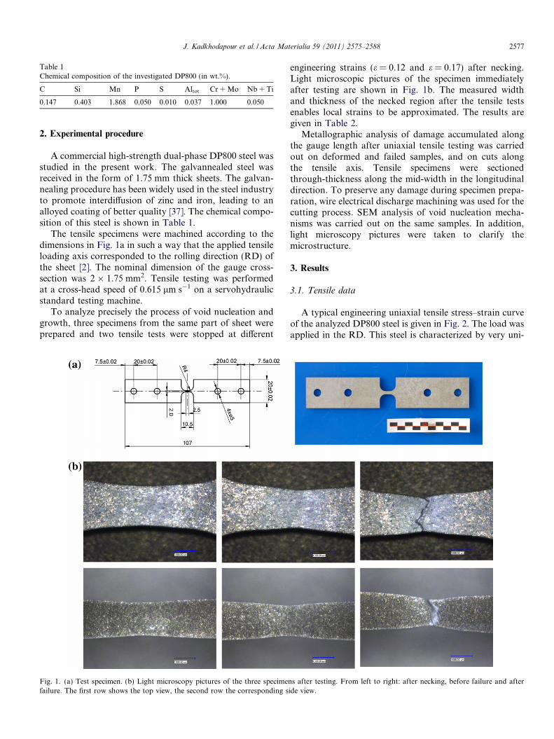
Table 1Chemical composition of the investigated DP800 (in wt.%).
C Si Mn P S Altot Cr + Mo Nb + Ti
0.147 0.403 1.868 0.050 0.010 0.037 1.000 0.050
J. Kadkhodapour et al. / Acta Materialia 59 (2011) 2575–2588 2577
2. Experimental procedure
A commercial high-strength dual-phase DP800 steel wasstudied in the present work. The galvannealed steel wasreceived in the form of 1.75 mm thick sheets. The galvan-nealing procedure has been widely used in the steel industryto promote interdiffusion of zinc and iron, leading to analloyed coating of better quality [37]. The chemical compo-sition of this steel is shown in Table 1.
The tensile specimens were machined according to thedimensions in Fig. 1a in such a way that the applied tensileloading axis corresponded to the rolling direction (RD) ofthe sheet [2]. The nominal dimension of the gauge cross-section was 2 � 1.75 mm2. Tensile testing was performedat a cross-head speed of 0.615 lm s�1 on a servohydraulicstandard testing machine.
To analyze precisely the process of void nucleation andgrowth, three specimens from the same part of sheet wereprepared and two tensile tests were stopped at different
Fig. 1. (a) Test specimen. (b) Light microscopy pictures of the three specimefailure. The first row shows the top view, the second row the corresponding s
engineering strains (e = 0.12 and e = 0.17) after necking.Light microscopic pictures of the specimen immediatelyafter testing are shown in Fig. 1b. The measured widthand thickness of the necked region after the tensile testsenables local strains to be approximated. The results aregiven in Table 2.
Metallographic analysis of damage accumulated alongthe gauge length after uniaxial tensile testing was carriedout on deformed and failed samples, and on cuts alongthe tensile axis. Tensile specimens were sectionedthrough-thickness along the mid-width in the longitudinaldirection. To preserve any damage during specimen prepa-ration, wire electrical discharge machining was used for thecutting process. SEM analysis of void nucleation mecha-nisms was carried out on the same samples. In addition,light microscopy pictures were taken to clarify themicrostructure.
3. Results
3.1. Tensile data
A typical engineering uniaxial tensile stress–strain curveof the analyzed DP800 steel is given in Fig. 2. The load wasapplied in the RD. This steel is characterized by very uni-
ns after testing. From left to right: after necking, before failure and afteride view.
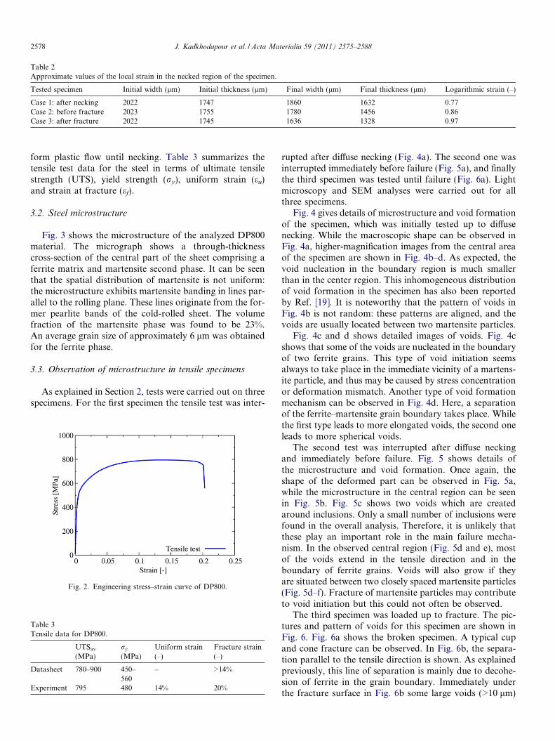
Table 2Approximate values of the local strain in the necked region of the specimen.
Tested specimen Initial width (lm) Initial thickness (lm) Final width (lm) Final thickness (lm) Logarithmic strain (–)
Case 1: after necking 2022 1747 1860 1632 0.77Case 2: before fracture 2023 1755 1780 1456 0.86Case 3: after fracture 2022 1745 1636 1328 0.97
2578 J. Kadkhodapour et al. / Acta Materialia 59 (2011) 2575–2588
form plastic flow until necking. Table 3 summarizes thetensile test data for the steel in terms of ultimate tensilestrength (UTS), yield strength (ry), uniform strain (eu)and strain at fracture (ef).
3.2. Steel microstructure
Fig. 3 shows the microstructure of the analyzed DP800material. The micrograph shows a through-thicknesscross-section of the central part of the sheet comprising aferrite matrix and martensite second phase. It can be seenthat the spatial distribution of martensite is not uniform:the microstructure exhibits martensite banding in lines par-allel to the rolling plane. These lines originate from the for-mer pearlite bands of the cold-rolled sheet. The volumefraction of the martensite phase was found to be 23%.An average grain size of approximately 6 lm was obtainedfor the ferrite phase.
3.3. Observation of microstructure in tensile specimens
As explained in Section 2, tests were carried out on threespecimens. For the first specimen the tensile test was inter-
Fig. 2. Engineering stress–strain curve of DP800.
Table 3Tensile data for DP800.
UTSav
(MPa)ry
(MPa)Uniform strain(–)
Fracture strain(–)
Datasheet 780–900 450–560
– >14%
Experiment 795 480 14% 20%
rupted after diffuse necking (Fig. 4a). The second one wasinterrupted immediately before failure (Fig. 5a), and finallythe third specimen was tested until failure (Fig. 6a). Lightmicroscopy and SEM analyses were carried out for allthree specimens.
Fig. 4 gives details of microstructure and void formationof the specimen, which was initially tested up to diffusenecking. While the macroscopic shape can be observed inFig. 4a, higher-magnification images from the central areaof the specimen are shown in Fig. 4b–d. As expected, thevoid nucleation in the boundary region is much smallerthan in the center region. This inhomogeneous distributionof void formation in the specimen has also been reportedby Ref. [19]. It is noteworthy that the pattern of voids inFig. 4b is not random: these patterns are aligned, and thevoids are usually located between two martensite particles.
Fig. 4c and d shows detailed images of voids. Fig. 4cshows that some of the voids are nucleated in the boundaryof two ferrite grains. This type of void initiation seemsalways to take place in the immediate vicinity of a martens-ite particle, and thus may be caused by stress concentrationor deformation mismatch. Another type of void formationmechanism can be observed in Fig. 4d. Here, a separationof the ferrite–martensite grain boundary takes place. Whilethe first type leads to more elongated voids, the second oneleads to more spherical voids.
The second test was interrupted after diffuse neckingand immediately before failure. Fig. 5 shows details ofthe microstructure and void formation. Once again, theshape of the deformed part can be observed in Fig. 5a,while the microstructure in the central region can be seenin Fig. 5b. Fig. 5c shows two voids which are createdaround inclusions. Only a small number of inclusions werefound in the overall analysis. Therefore, it is unlikely thatthese play an important role in the main failure mecha-nism. In the observed central region (Fig. 5d and e), mostof the voids extend in the tensile direction and in theboundary of ferrite grains. Voids will also grow if theyare situated between two closely spaced martensite particles(Fig. 5d–f). Fracture of martensite particles may contributeto void initiation but this could not often be observed.
The third specimen was loaded up to fracture. The pic-tures and pattern of voids for this specimen are shown inFig. 6. Fig. 6a shows the broken specimen. A typical cupand cone fracture can be observed. In Fig. 6b, the separa-tion parallel to the tensile direction is shown. As explainedpreviously, this line of separation is mainly due to decohe-sion of ferrite in the grain boundary. Immediately underthe fracture surface in Fig. 6b some large voids (>10 lm)
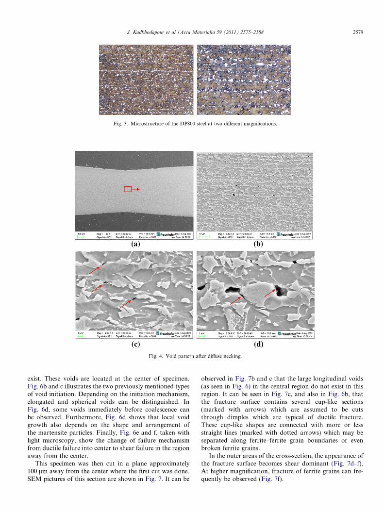
Fig. 3. Microstructure of the DP800 steel at two different magnifications.
Fig. 4. Void pattern after diffuse necking.
J. Kadkhodapour et al. / Acta Materialia 59 (2011) 2575–2588 2579
exist. These voids are located at the center of specimen.Fig. 6b and c illustrates the two previously mentioned typesof void initiation. Depending on the initiation mechanism,elongated and spherical voids can be distinguished. InFig. 6d, some voids immediately before coalescence canbe observed. Furthermore, Fig. 6d shows that local voidgrowth also depends on the shape and arrangement ofthe martensite particles. Finally, Fig. 6e and f, taken withlight microscopy, show the change of failure mechanismfrom ductile failure into center to shear failure in the regionaway from the center.
This specimen was then cut in a plane approximately100 lm away from the center where the first cut was done.SEM pictures of this section are shown in Fig. 7. It can be
observed in Fig. 7b and c that the large longitudinal voids(as seen in Fig. 6) in the central region do not exist in thisregion. It can be seen in Fig. 7c, and also in Fig. 6b, thatthe fracture surface contains several cup-like sections(marked with arrows) which are assumed to be cutsthrough dimples which are typical of ductile fracture.These cup-like shapes are connected with more or lessstraight lines (marked with dotted arrows) which may beseparated along ferrite–ferrite grain boundaries or evenbroken ferrite grains.
In the outer areas of the cross-section, the appearance ofthe fracture surface becomes shear dominant (Fig. 7d–f).At higher magnification, fracture of ferrite grains can fre-quently be observed (Fig. 7f).
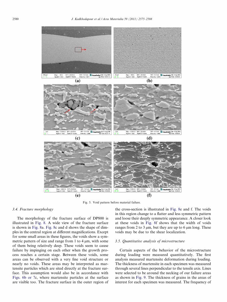
Fig. 5. Void pattern before material failure.
2580 J. Kadkhodapour et al. / Acta Materialia 59 (2011) 2575–2588
3.4. Fracture morphology
The morphology of the fracture surface of DP800 isillustrated in Fig. 8. A wide view of the fracture surfaceis shown in Fig. 8a. Fig. 8c and d shows the shape of dim-ples in the central region at different magnifications. Exceptfor some small areas in these figures, the voids show a sym-metric pattern of size and range from 1 to 4 lm, with someof them being relatively deep. These voids seem to causefailure by impinging on each other when the growth pro-cess reaches a certain stage. Between these voids, someareas can be observed with a very fine void structure ornearly no voids. These areas may be interpreted as mar-tensite particles which are sited directly at the fracture sur-face. This assumption would also be in accordance withFigs. 6b or 7c, where martensite particles at the surfaceare visible too. The fracture surface in the outer region of
the cross-section is illustrated in Fig. 8e and f. The voidsin this region change to a flatter and less symmetric patternand loose their deeply symmetric appearance. A closer lookat these voids in Fig. 8f shows that the width of voidsranges from 2 to 3 lm, but they are up to 6 lm long. Thesevoids may be due to the shear localization.
3.5. Quantitative analysis of microstructure
Certain aspects of the behavior of the microstructureduring loading were measured quantitatively. The firstanalysis measured martensite deformation during loading.The thickness of martensite in each specimen was measuredthrough several lines perpendicular to the tensile axis. Lineswere selected to be around the necking of our failure areasas shown in Fig. 9. The thickness of grains in the areas ofinterest for each specimen was measured. The frequency of
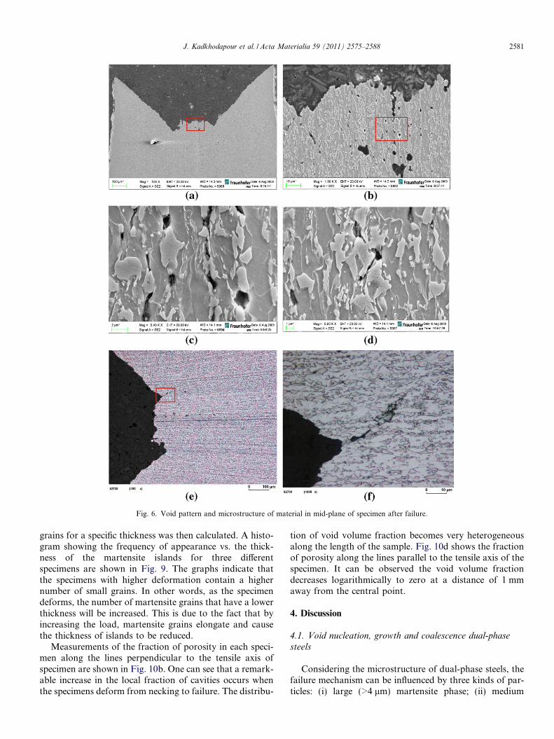
Fig. 6. Void pattern and microstructure of material in mid-plane of specimen after failure.
J. Kadkhodapour et al. / Acta Materialia 59 (2011) 2575–2588 2581
grains for a specific thickness was then calculated. A histo-gram showing the frequency of appearance vs. the thick-ness of the martensite islands for three differentspecimens are shown in Fig. 9. The graphs indicate thatthe specimens with higher deformation contain a highernumber of small grains. In other words, as the specimendeforms, the number of martensite grains that have a lowerthickness will be increased. This is due to the fact that byincreasing the load, martensite grains elongate and causethe thickness of islands to be reduced.
Measurements of the fraction of porosity in each speci-men along the lines perpendicular to the tensile axis ofspecimen are shown in Fig. 10b. One can see that a remark-able increase in the local fraction of cavities occurs whenthe specimens deform from necking to failure. The distribu-
tion of void volume fraction becomes very heterogeneousalong the length of the sample. Fig. 10d shows the fractionof porosity along the lines parallel to the tensile axis of thespecimen. It can be observed the void volume fractiondecreases logarithmically to zero at a distance of 1 mmaway from the central point.
4. Discussion
4.1. Void nucleation, growth and coalescence dual-phase
steels
Considering the microstructure of dual-phase steels, thefailure mechanism can be influenced by three kinds of par-ticles: (i) large (>4 lm) martensite phase; (ii) medium
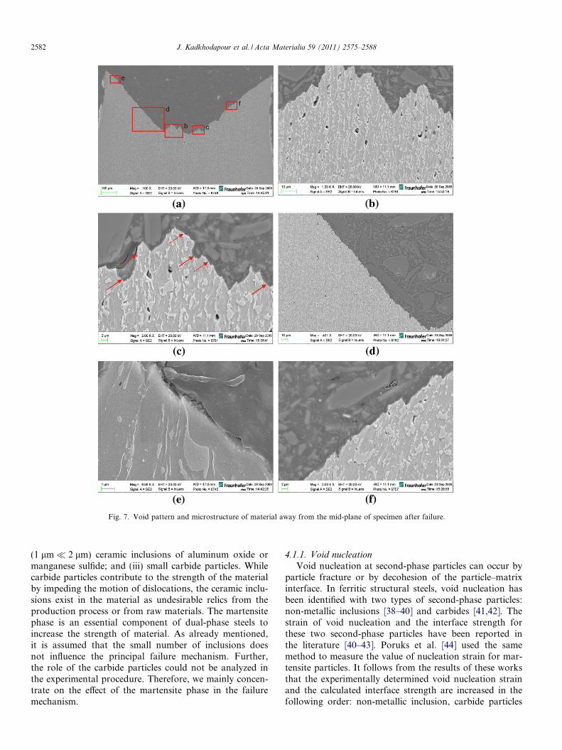
Fig. 7. Void pattern and microstructure of material away from the mid-plane of specimen after failure.
2582 J. Kadkhodapour et al. / Acta Materialia 59 (2011) 2575–2588
(1 lm� 2 lm) ceramic inclusions of aluminum oxide ormanganese sulfide; and (iii) small carbide particles. Whilecarbide particles contribute to the strength of the materialby impeding the motion of dislocations, the ceramic inclu-sions exist in the material as undesirable relics from theproduction process or from raw materials. The martensitephase is an essential component of dual-phase steels toincrease the strength of material. As already mentioned,it is assumed that the small number of inclusions doesnot influence the principal failure mechanism. Further,the role of the carbide particles could not be analyzed inthe experimental procedure. Therefore, we mainly concen-trate on the effect of the martensite phase in the failuremechanism.
4.1.1. Void nucleation
Void nucleation at second-phase particles can occur byparticle fracture or by decohesion of the particle–matrixinterface. In ferritic structural steels, void nucleation hasbeen identified with two types of second-phase particles:non-metallic inclusions [38–40] and carbides [41,42]. Thestrain of void nucleation and the interface strength forthese two second-phase particles have been reported inthe literature [40–43]. Poruks et al. [44] used the samemethod to measure the value of nucleation strain for mar-tensite particles. It follows from the results of these worksthat the experimentally determined void nucleation strainand the calculated interface strength are increased in thefollowing order: non-metallic inclusion, carbide particles
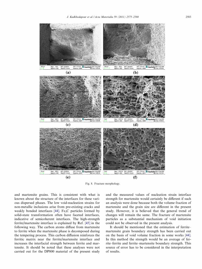
Fig. 8. Fracture morphology.
J. Kadkhodapour et al. / Acta Materialia 59 (2011) 2575–2588 2583
and martensite grains. This is consistent with what isknown about the structure of the interfaces for these vari-ous dispersed phases. The low void-nucleation strains fornon-metallic inclusions arise from pre-existing cracks andweakly bonded interfaces [44]. Fe3C particles formed bysolid-state transformation often have faceted interfaces,indicative of semicoherent interfaces. The high-strengthferrite/martensite interface is explained by Ref. [45] in thefollowing way. The carbon atoms diffuse from martensiteto ferrite when the martensite phase is decomposed duringthe tempering process. This carbon diffusion reinforces theferritic matrix near the ferrite/martensite interface andincreases the interfacial strength between ferrite and mar-tensite. It should be noted that these analyses were notcarried out for the DP800 material of the present study
and the measured values of nucleation strain interfacestrength for martensite would certainly be different if suchan analysis were done because both the volume fraction ofmartensite and the grain size are different in the presentstudy. However, it is believed that the general trend ofchanges will remain the same. The fracture of martensiteparticles as a substantial mechanism of void initiationcould not be observed in the present analysis.
It should be mentioned that the estimation of ferrite–martensite grain boundary strength has been carried outon the basis of void volume fraction in some works [44].In this method the strength would be an average of fer-rite–ferrite and ferrite–martensite boundary strength. Thissource of error has to be considered in the interpretationof results.
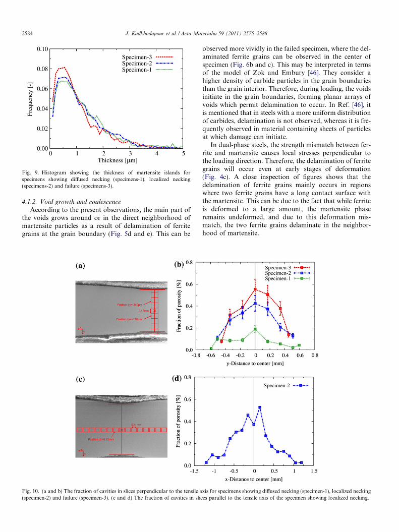
Fig. 9. Histogram showing the thickness of martensite islands forspecimens showing diffused necking (specimens-1), localized necking(specimens-2) and failure (specimens-3).
2584 J. Kadkhodapour et al. / Acta Materialia 59 (2011) 2575–2588
4.1.2. Void growth and coalescence
According to the present observations, the main part ofthe voids grows around or in the direct neighborhood ofmartensite particles as a result of delamination of ferritegrains at the grain boundary (Fig. 5d and e). This can be
Fig. 10. (a and b) The fraction of cavities in slices perpendicular to the tensile a(specimen-2) and failure (specimen-3). (c and d) The fraction of cavities in slic
observed more vividly in the failed specimen, where the del-aminated ferrite grains can be observed in the center ofspecimen (Fig. 6b and c). This may be interpreted in termsof the model of Zok and Embury [46]. They consider ahigher density of carbide particles in the grain boundariesthan the grain interior. Therefore, during loading, the voidsinitiate in the grain boundaries, forming planar arrays ofvoids which permit delamination to occur. In Ref. [46], itis mentioned that in steels with a more uniform distributionof carbides, delamination is not observed, whereas it is fre-quently observed in material containing sheets of particlesat which damage can initiate.
In dual-phase steels, the strength mismatch between fer-rite and martensite causes local stresses perpendicular tothe loading direction. Therefore, the delamination of ferritegrains will occur even at early stages of deformation(Fig. 4c). A close inspection of figures shows that thedelamination of ferrite grains mainly occurs in regionswhere two ferrite grains have a long contact surface withthe martensite. This can be due to the fact that while ferriteis deformed to a large amount, the martensite phaseremains undeformed, and due to this deformation mis-match, the two ferrite grains delaminate in the neighbor-hood of martensite.
xis for specimens showing diffused necking (specimen-1), localized neckinges parallel to the tensile axis of the specimen showing localized necking.
J. Kadkhodapour et al. / Acta Materialia 59 (2011) 2575–2588 2585
Considering the model of Zok and Embury [46], delam-ination of ferrite–martensite interfaces might be conceiv-able. However, from previous considerations it should benoted that the ferrite–martensite grain boundary isassumed to be stronger than the ferrite–ferrite grain bound-ary. In this model, the high density of carbide particles isthe cause of separation or delamination in the grain bound-ary. The carbide particles travel from the ferrite grains tothe grain boundary, and it is well known that martensiteis free of carbide particles. It can thus be concluded thatthe density of carbide particles in the ferrite–ferrite grainboundary is approximately twice the density in theferrite–martensite grain boundary. As a result, the ferrite–martensite grain boundary is stronger than the ferrite–ferrite grain boundary. Direct observation of the carbideparticles in the specimen would have required transmissionelectron microscopy testing, which was not carried out inthis study.
Considering the dual-phase steel microstructure, theinfluence of the martensite phase on the void growth andvoid coalescence mechanism has to be clarified. Especiallyimportant for understanding of the failure mechanism ishow the voids are linked to each other and what the dom-inant kind of fracture mechanism is. These questions willbe addressed to some extent in the next section.
4.2. Proposed explanation of the failure mechanism in dual-
phase steel through simulation and experimental analysis
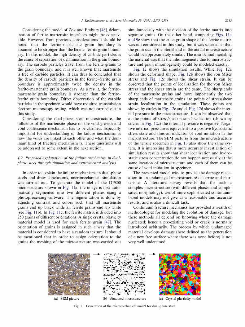
In order to explain the failure mechanisms in dual-phasesteels and draw conclusions, micromechanical simulationwas carried out. To generate the model of the DP800microstructure shown in Fig. 11a, the image is first auto-matically segmented into two different phases using aphotoprocessing software. The segmentation is done byadjusting contrast and colors such that all martensitegrains end up black while all ferrite grains end up white(see Fig. 11b). In Fig. 11c, the ferrite matrix is divided into250 grains of different orientations. A single crystal plasticitymaterial model is used for each ferrite grain [47]. Theorientation of grains is assigned in such a way that thematerial is considered to have a random texture. It shouldbe mentioned that in order to assign orientation to thegrains the meshing of the microstructure was carried out
Fig. 11. Generation of the micromech
simultaneously with the division of the ferrite matrix intoseparate grains. On the other hand, comparing Figs. 11aand 9c show that the exact grain shape of the ferrite matrixwas not considered in this study, but it was selected so thatthe grain size in the model and in the actual microstructurewould be approximately similar. The idea behind modelingthe material was that the inhomogeneity due to microstruc-ture and grain inhomogeneity could be modeled exactly.
Fig. 12 shows the simulation results. While Fig. 12ashows the deformed shape, Fig. 12b shows the von Misesstress and Fig. 12c shows the shear strain. It can beobserved that the points of localization for the von Misesstress and the shear strain are the same. The sharp endsof the martensite grains and more importantly the twosharp ends of martensite grains are points of stress/shearstrain localization in the simulation. These points areshown by circles in Fig. 12c and d. Fig. 12d shows the inter-nal pressure in the microstructure. It can be observed thatat the points of stress/shear strain localization (shown bycircles in Fig. 12c) the internal pressure is negative. Nega-tive internal pressure is equivalent to a positive hydrostaticstress state and thus an indicator of void initiation in themicrostructure. The SEM pictures from the microstructureof the tensile specimen in Fig. 13 also show the same sys-tem. It is interesting that a more accurate investigation ofsimulation results show that shear localization and hydro-static stress concentration do not happen necessarily at thesame location of microstructure and each of them can because of void initiation in specimen.
The presented model tries to predict the damage nucle-ation in an undamaged microstructure of ferrite and mar-tensite. A literature survey reveals that for such acomplex microstructure (with different phases and compli-cated morphology), use of more sophisticated continuum-based models may not give us a reasonable and accurateresults, and is also a difficult task.
Continuum fracture mechanics has provided a wealth ofmethodologies for modeling the evolution of damage, butthese methods all depend on knowing where the damagenucleated; hence a pre-existing void or crack is normallyintroduced arbitrarily. The process by which undamagedmaterial develops damage (here defined as the generationof a new free surface where there was none before) is notvery well understood.
anical model for dual-phase steel.
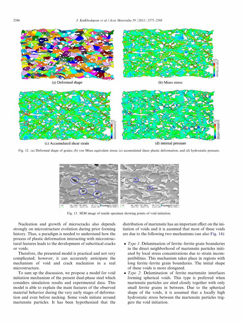
Fig. 12. (a) Deformed shape of grains; (b) von Mises equivalent stress; (c) accumulated shear plastic deformation; and (d) hydrostatic pressure.
Fig. 13. SEM image of tensile specimen showing points of void initiation.
2586 J. Kadkhodapour et al. / Acta Materialia 59 (2011) 2575–2588
Nucleation and growth of microcracks also dependsstrongly on microstructure evolution during prior forminghistory. Thus, a paradigm is needed to understand how theprocess of plastic deformation interacting with microstruc-tural features leads to the development of subcritical cracksor voids.
Therefore, the presented model is practical and not verycomplicated; however, it can accurately anticipate themechanism of void and crack nucleation in a realmicrostructure.
To sum up the discussion, we propose a model for voidinitiation mechanism of the present dual-phase steel whichconsiders simulation results and experimental data. Thismodel is able to explain the main features of the observedmaterial behavior during the very early stages of deforma-tion and even before necking. Some voids initiate aroundmartensite particles. It has been hypothesized that the
distribution of martensite has an important effect on the ini-tiation of voids and it is assumed that most of these voidsare due to the following two mechanisms (see also Fig. 14):
� Type 1: Delamination of ferrite–ferrite grain boundariesin the direct neighborhood of martensite particles initi-ated by local stress concentrations due to strain incom-patibilities. This mechanism takes place in regions withlong ferrite–ferrite grain boundaries. The initial shapeof these voids is more elongated.� Type 2: Delamination of ferrite–martensite interfaces
forming spherical voids. This type is preferred whenmartensite particles are sited closely together with onlysmall ferrite grains in between. Due to the sphericalshape of the voids, it is assumed that a locally highhydrostatic stress between the martensite particles trig-gers the void initiation.
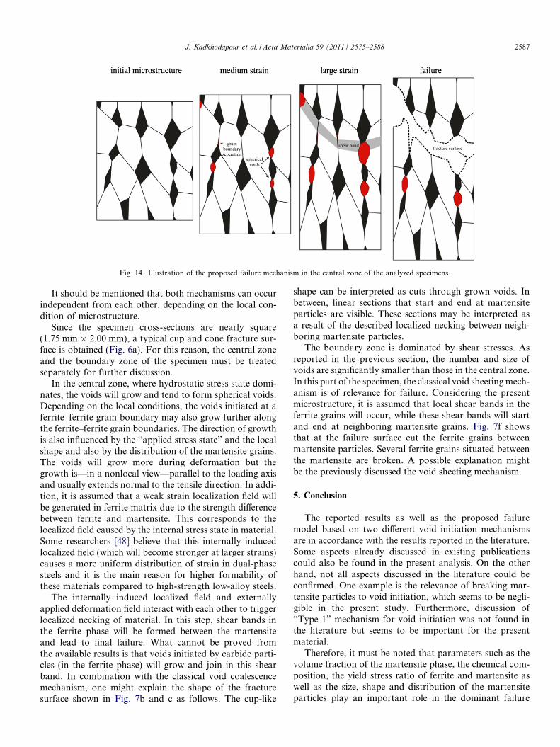
Fig. 14. Illustration of the proposed failure mechanism in the central zone of the analyzed specimens.
J. Kadkhodapour et al. / Acta Materialia 59 (2011) 2575–2588 2587
It should be mentioned that both mechanisms can occurindependent from each other, depending on the local con-dition of microstructure.
Since the specimen cross-sections are nearly square(1.75 mm � 2.00 mm), a typical cup and cone fracture sur-face is obtained (Fig. 6a). For this reason, the central zoneand the boundary zone of the specimen must be treatedseparately for further discussion.
In the central zone, where hydrostatic stress state domi-nates, the voids will grow and tend to form spherical voids.Depending on the local conditions, the voids initiated at aferrite–ferrite grain boundary may also grow further alongthe ferrite–ferrite grain boundaries. The direction of growthis also influenced by the “applied stress state” and the localshape and also by the distribution of the martensite grains.The voids will grow more during deformation but thegrowth is—in a nonlocal view—parallel to the loading axisand usually extends normal to the tensile direction. In addi-tion, it is assumed that a weak strain localization field willbe generated in ferrite matrix due to the strength differencebetween ferrite and martensite. This corresponds to thelocalized field caused by the internal stress state in material.Some researchers [48] believe that this internally inducedlocalized field (which will become stronger at larger strains)causes a more uniform distribution of strain in dual-phasesteels and it is the main reason for higher formability ofthese materials compared to high-strength low-alloy steels.
The internally induced localized field and externallyapplied deformation field interact with each other to triggerlocalized necking of material. In this step, shear bands inthe ferrite phase will be formed between the martensiteand lead to final failure. What cannot be proved fromthe available results is that voids initiated by carbide parti-cles (in the ferrite phase) will grow and join in this shearband. In combination with the classical void coalescencemechanism, one might explain the shape of the fracturesurface shown in Fig. 7b and c as follows. The cup-like
shape can be interpreted as cuts through grown voids. Inbetween, linear sections that start and end at martensiteparticles are visible. These sections may be interpreted asa result of the described localized necking between neigh-boring martensite particles.
The boundary zone is dominated by shear stresses. Asreported in the previous section, the number and size ofvoids are significantly smaller than those in the central zone.In this part of the specimen, the classical void sheeting mech-anism is of relevance for failure. Considering the presentmicrostructure, it is assumed that local shear bands in theferrite grains will occur, while these shear bands will startand end at neighboring martensite grains. Fig. 7f showsthat at the failure surface cut the ferrite grains betweenmartensite particles. Several ferrite grains situated betweenthe martensite are broken. A possible explanation mightbe the previously discussed the void sheeting mechanism.
5. Conclusion
The reported results as well as the proposed failuremodel based on two different void initiation mechanismsare in accordance with the results reported in the literature.Some aspects already discussed in existing publicationscould also be found in the present analysis. On the otherhand, not all aspects discussed in the literature could beconfirmed. One example is the relevance of breaking mar-tensite particles to void initiation, which seems to be negli-gible in the present study. Furthermore, discussion of“Type 1” mechanism for void initiation was not found inthe literature but seems to be important for the presentmaterial.
Therefore, it must be noted that parameters such as thevolume fraction of the martensite phase, the chemical com-position, the yield stress ratio of ferrite and martensite aswell as the size, shape and distribution of the martensiteparticles play an important role in the dominant failure
2588 J. Kadkhodapour et al. / Acta Materialia 59 (2011) 2575–2588
mechanism. Further, the specimen shape, which influencesthe stress state in the gauge, should also be considered inthe discussions.
To conclude, a formulation of a general failure mecha-nism for dual-phase steels seems not to be applicable. Itis suggested that future work should concentrate ondescribing the principal failure mechanism based on the rel-evant parameter of the dual-phase steel material.
Acknowledgements
The authors are grateful for the financial support of theGerman Federal Ministry of Education and Research,which funded this study under Grant 03X0501E. They alsoacknowledge detailed discussions with Mr. Martin Moserand Dr. Herman Riedel from the Fraunhofer Institutefor Mechanics of Material IWM, Germany. The effort ofDr. Johannes Preußner on the pore volume measurementsis also appreciated.
References
[1] Kleiner M, Geiger M, Klaus A. Annals of the CIRP “ManufacturingTechnology”, 53rd general assembly of CIRP, Montreal, Canada, vol.52/2; 2003. p. 521–42.
[2] Cribb WR, Rigsbee JM. In: Kot RA, Morris JW, editors. Structureand properties of dual-phase steels. New York: AIME; 1979. p. 91–117.
[3] Mazinani M, Poole WJ. Metall Trans 2007;38A:328–39.[4] Bouaziz O, Embury JD. Mater Sci Forum 2007;539:42–50.[5] Avramovic-Cingara G, Ososkov Y, Jain MK, Wilkinson DS. Mater
Sci Eng 2009;516A:7–16.[6] Avramovic-Cingara G, Saleh ChAR, Jain MK, Wilkinson DS. Metall
Mater Trans 2009;40A:3117–27.[7] Prahl U, Papaefthymiou S, Uthaisangsuk V, Bleck W, Sietsma J, Van
der Zwaag S. Comput Mater Sci 2007;39:17–22.[8] Uthaisangsuk V, Prahl U, Munstermann S, Bleck W. Comput Mater
Sci 2008;43:43–50.[9] Calcagnotto M, Ponge D, Adachi Y, Raabe D. In: Proc 2nd
international symposium on steel science (ISSS 2009). Kyoto; 2009.[10] Calcagnotto M, Ponge D, Raabe D. Mater Sci Eng
2010;527A:7832–40.[11] Calcagnotto M, Adachi Y, Ponge D, Raabe D. Acta Mater
2011;59:658–70.[12] Sun X, Choi KS, Liu WN, Khaleel MA. Int J Plasticity
2009;25:1888–909.[13] Sun X, Choi KS, Soulami A, Liu WN, Khaleel MA. Mater Sci Eng
2009;526A:140–9.[14] Choi KS, Liu WN, Sun X, Khaleel MA. Metall Mater Trans
2009;40A:796–809.
[15] Ghadbeigi H, Pinna C, Celotto S, Yates JR. Mater Sci Eng2010;527A:5026–32.
[16] Tasan CC, Hoefnagels JPM, Geers MGD. Scripta Mater2010;62:835–8.
[17] Shen HP, Lei TC, Liu JZ. Mater Sci Technol 1986;2:28–33.[18] Kang J, Ososkov Y, Embury JD, Wilkinson DS. Scripta Mater
2007;56:999–1002.[19] Maire E, Bouaziz O, Michiel MD, Verdu C. Acta Mater
2008;18:4954–64.[20] Rashid MS. GM 980X-A paper 760206, Soc Auto Eng Cong, Detroit;
1977. p. 938–49.[21] Rashid MS, Cprek EB. Formability topics—metallic materials,
ASTM STP 647. Philadelphia, PA: American Society for Testingand Materials; 1978. p. 174–90.
[22] Balliger NK. Book 284. London: The Metals Society; 1982.[23] Gladman T. The physical metallurgy of microalloyed steels. London:
Institute of Materials; 1997.[24] Koo JY, Thomas G. In: Davenport AT, editor. Weight applications.
Formable HSLA and dual phase steels. New York: AIME; 1977. p.40–55.
[25] Sun S, Pugh M. Mater Sci Eng 2002;335:298–308.[26] Steinbrunner DL, Krauss G. Metall Trans 1988;9(A):579–89.[27] Kang S, Kwon H. Metall Trans 1987;18(A):1587–92.[28] Gerbase J, Embury JD, Hobbs RM. In: Kot RA, Morris JW, editors.
Structure and properties of dual-phase steels. New York: TMS-AIME; 1979. p. 118–143.
[29] Speich GR, Miller RL. In: Kot RA, Morris JW, editors. Structureand properties of dual-phase steels. New York: TMS-AIME; 1979. p.145–182.
[30] Korzekwa DA, Lawson RD, Matlock DK, Krauss G. Scripta Metall1980;14:1023–8.
[31] Szewczyk AF, Gurland J. Metall Trans 1982;13(A):1821–6.[32] Nam WJ, Bae CM. J Mater Sci 1999;34:5661–8.[33] Ahmed E, Tanvir M, Kanwar LA, Akhter JI. J Mater Eng Perform
2000;9(3):306–10.[34] Erdogan M. J Mater Sci 2002;37:3623–30.[35] Suh D, Kwon D, Lee S, Kim NJ. Metall Trans 1997;28A:504–9.[36] Tomota Y, Tamura I. Trans Iron Steel Inst Jpn 1982;22:665–77.[37] Almeida E, Morcillo M. Surf Coat Technol 2000;124:180–9.[38] Garrison Jr WM, Moody NR. J Phys Chem Solids 1987;48:1035–74.[39] Spitzig WA, Smelser RE, Richmond O. Acta Metall 1988;36:1201–11.[40] Qiu H, Mori H, Enoki M, Teruo K. ISIJ Int 1999;39:358–64.[41] LeRoy G, Embury JD, Edwards G, Ashby MF. Acta Metall
1981;23:1509–22.[42] Kwon D. Scripta Metall 1988;22:1161–4.[43] Kosco JB, Koss DA. Metall Trans 1993;24A:681–7.[44] Poruks P, Yakubtsov I, Boyd JD. Scripta Mater 2006;54:41–5.[45] Lee HS, Hwang B, Lee S, Lee CG, Kim SJ. Metall Mater Trans
2004;35A:2371–82.[46] Zok F, Embury JD. Metall Trans 1990;21A:2565–75.[47] Kadkhodapour J, Butz A, Ziaei-Rad S, Schmauder S. Int J Plasticity
2010. doi:10.1016/j.ijplas.2010.12.001.[48] Marder AR. Metall Mater Trans 1982;13A:85–92.