pompa a membrana diaphragm pump zip182 pompe a … · 2 pompa a membrana / diaphragm pump / pompe a...
TRANSCRIPT

ISTRUZIONI D' USOINSTRUCTION MANUALMANUEL D'EMPLOIBETRIEBSANLEITUNG
POMPA A MEMBRANADIAPHRAGM PUMPPOMPE A MEMBRANEDOPPELMEMBRANPUMPE
REV. 03/08
coloratecni®
pompe pneumatiche - air powered pumpsWagner Colora s.r.l.(Socio Unico)
Tel. 39/039 625021 r.a. - Telefax 39/039 6851800Via Fermi, 3
20040 BURAGO DI MOLGORA (MI) ITALIA
ZIP182VERSIONE IN METALLOMETALLIC VERSIONVERSION MÉTALLIQUEMETALLAUSFÜHRUNG
ZZ175 - 3832216

2
POMPA A MEMBRANA / DIAPHRAGM PUMP /POMPE A MEMBRANE/DOPPELMEMBRANEPUMPE
INDICE:
1. DATI IDENTIFICATIVI DELLA Pag. 4MACCHINA
1.1 Lettera alla consegna Pag. 41.2 Identificazione Pag. 61.3 Garanzia Pag. 61.4 Centri di assistenza Pag. 8
2. GENERALITA� Pag. 102.1 Osservazioni preliminari Pag. 102.2 Norme generali di sicurezza Pag. 102.3 Prescrizioni di sicurezza Pag. 122.4 Rischi residui Pag. 142.5 Compatibilità chimica dei materiali Pag. 162.6 Arresto emergenza Pag. 182.7 Istruzioni di sicurezza Pag. 22
3. DESCRIZIONE DELLA MACCHINA Pag. 30E DATI TECNICI
3.1 Descrizione del principio di Pag. 30funzionamento della pompa
3.2 Caratteristiche tecniche Pag. 343.3 Schema funzionamento pompa Pag. 353.4 Ricambi Pag. 363.5 Messa fuori servizio Pag. 36
4. INSTALLAZIONE Pag. 384.1 Trasporto e immagazzinamento Pag. 384.2 Installazione Pag. 40
5. PROCEDURE DI IMPIEGO Pag. 465.1 Operazioni preliminari Pag. 465.2 Funzionamento Pag. 50
6. PULIZIA E MANUTENZIONE Pag. 546.1 Manutenzione della macchina Pag. 54
7. RICERCA GUASTI Pag. 62
8. CATALOGO PARTI DI RICAMBIO Pag. 64
INDEX:
1. PUMP IDENTIFICATION DATA Page 41.1 Letter to the customer Page 41.2 Identification Page 61.3 Warranty Page 61.4 Service centres Page 8
2. GENERAL INFORMATION Page 102.1 Preliminary notes Page 102.2 General safety standards Page 102.3 Safety instructions Page 122.4 Remaining risks Page 142.5 Material chemical compatibility Page 162.6 Emergency stop Page 182.7 Safety instructions Page 22
3. MACHINE DESCRIPTION AND Page 30TECHNICAL SPECIFICATIONS
3.1 Pump operating principle Page 303.2 Technical features Page 343.3 Diagram illustrating Page 35
the pump functioning3.4 Spare parts Page 363.5 Dismantling Page 36
4. INSTALLATION Page 384.1 Transport and storage Page 384.2 Installment Page 40
5. OPERATION PROCEDURES Page 465.1 Preliminary operations Page 465.2 Functioning Page 50
6. CLEANING AND MAINTENANCE Page 546.1 Machine maintenance Page 54
7. TROUBLESHOOTING Page 62
8. SPARE PARTS CATALOGUE Page 64

3
POMPA A MEMBRANA / DIAPHRAGM PUMP / POMPE A MEMBRANE/DOPPELMEMBRANEPUMPE
SOMMAIRE:
1. DONNEES D� IDENTIFICATION Page 4DE LA MACHINE
1.1 Lettre a la livraison Page 4
INHALT:
1. KENNDATEN DER MASCHINE Seite 51.1 Begleitbrief Seite 51.2 Identifikation Seite 71.3 Garantie Seite 71.4 Kundendienststellen Seite 9
2. ALLGEMEINES Seite 112.1 Vorläufiges Seite 112.2 Allgemeine Sicherheitsvorschriften Seite 112.3 Sicherheitsvorschriften Seite 132.4 Restrisiken Seite 152.5 Chemische Verträglichkeit Seite 172.6 Notstopp Seite 192.7 Sicherheitsanweisungen Seite 23
3. BESCHREIBUNG DER MASCHINEUND TECHNISCHE DATEN Seite 31
3.1 Beschreibung des Seite 31Funktionsprizips der Pumpe
3.2 Technische Merkmale Seite 343.3 Funktionsweise der Pumpe Seite 353.4 Ersatzteile Seite 373.5 Ausserbetriebnahme Seite 37
4. INSTALLATION Seite 394.1 Transport und Lagerung Seite 394.2 Installation Seite 41
5. BETRIEB Seite 475.1 Vorbereitung Seite 475.2 Betrieb Seite 51
6. REINIGUNG UND WARTUNG Seite 556.1 Wartung der Maschine Seite 55
7. FEHLERSUCHE Seite 63
8. ERSATZTEILE KATALOG Seite 65
1.2 Identification Page 61.3 Garantie Page 61.4 Centres d� assistance Page 8
2. GENERALITIES Page 102.1 Remarques preliminaires Page 102.2 Normes generales de securite Page 102.3 Prescriptions de securite Page 122.4 Risques residuels Page 142.5 Compatibilite chimique Page 16
des materiaux2.6 Arret d� urgence Page 182.7 Instructions de securite Page 22
3. DESCRIPTION DE LA MACHINE Page 30ET DONNEES
3.1 Description du principe Page 30de fonctionnement de la pompe
3.2 Caracteristiques tecniques Page 343.3 Schema de fonctionnement pompe Page 353.4 Pieces de rechange Page 363.5 Mise hors service Page 36
4. INSTALLATION Page 384.1 Transport et entreposage Page 384.2 Installation Page 40
5. PROCÉDURES D� EMPLOI Page 465.1 Operations preliminaires Page 465.2 Fonctionnement Page 50
6. NETTOYAGE ET ENTRETIEN Page 546.1 Entretien de la machine Page 54
7. RECHERCHE PANNES Page 63
8. CATALOGUE PIECES Page 64DE RECHANGE

4
POMPA A MEMBRANA / DIAPHRAGM PUMP /POMPE A MEMBRANE/DOPPELMEMBRANEPUMPE
1. DATI IDENTIFICATIVIDELLA MACCHINA
1.1 LETTERA ALLA CONSEGNA
Egregio Signore
1. MACHINEIDENTIFICATION DATA
1. DONNEESD'IDENTIFICATION DELA MACHINE
1.1 LETTRE A LA LIVRAISON1.1 LETTER TO THE CUSTOMER
- POTENZA- ROBUSTEZZA- AFFIDABILITA'
problems, thus improving its efficiencyand prolonging its lifetime.
you with any question or problem youmay have.
Questo apparecchio è stato fabbricatoutilizzando i materiali migliori e letecniche costruttive più moderne.I particolari a contatto con il prodotto(valvole, membrane, coperchi ecollettori), costruiti con materiali aventicaratteristiche di elevata resistenzachimica e fisica, consentono di trattarei liquidi più disparati garantendo,insieme all� esperienza dei ns.Tecnici,le qualità di questa apparecchiatura:
Le ricordiamo che una buonaconoscenza dell� apparecchiaturaaffina sensibilmente I�uso e che unimpiego corretto consente di evitaremolti problemi, migliora il rendimentoe prolunga la duratadell�apparecchiatura stessa.
Legga quindi attentamente le istruzioniche seguono prima di mettere infunzione I�apparecchiatura.
La mancata osservanza delleindicazioni riportate in questo fascicoloo l�uso improprio dell�apparecchiaturada parte di personale non qualificatoe non autorizzato può provocare deirischi alle persone o all�ambientecausati da fuoriuscita di fluidi inpressione.
II nostro Servizio Tecnico diAssistenza è a Sua completadisposizione per ogni dubbio oproblema ci interpelli, anchetelefonicamente.
WAGNER colora S.r.l
We would like to remind you , that agood knowledge of the equipment willhelp you to operate it and that a correctuse of the appliance will avoid, many
Please read carefully the followinginstructions before operating theequipment.
Failure to observe the instructionsgiven in this booklet as well asmachinery misuse by unqualified orunauthorized personnel may result indangers to people as well as to theenvironment, as a consequence ofpressurized fluid discharge.
Do not hesitate to contact us in writingor calling Technical ServiceDepartment: we will be glad to help
WAGNER colora S.r.l
This equipment has been manufacturedusing the best materials and accordingto the most advanced manufacturingtechniques available today.All components coming into directcontact with the product, such asvalves, diaphragms, covers andmanifolds, have been manufacturedusing materials which are highlyresistant to physical and chemicalwear, thus allowing you to handle themost diverse liquids.These elements, together with theexperience of the technicians whodesigned it, are a guarantee of thisequipment good qualities, i.e.:
Dear Sir,
- POWER- STURDINESS- RELIABILITY
MonsieurCet appareil a été fabriqué en utilisantles meilleurs matériaux et lestechniques de construction les plusmodernes.Les pièces entrant en contact avec leproduit (valves, membranes,couvercles et collecteurs) ont étéconstruites en utilisant des matériauxpossédant des caractéristiques derésistance chimique et physiqueélevée, permettant de traiter lesliquides les plus disparates tout engarantissant, également grâce àl'expérience des Techniciens, lesqualités suivantes de cet appareil:
- PUISSANCE- ROBUSTESSE- FIABILITENous vous rappelons qu'une bonneconnaissance de qu'une utilisationcorrecte vous permettra d'éviter denombreux problèmes, en améliorantle rendement et en prolongeant ladurée de vie dudit appareil.
Par conséquent, lire attentivement lesinstructions qui suivent avant demettre l'appareil en service.
Le non-respect des indicationsillustrées dans ce fascicule ou l'usageincorrect de l'appareil de la part d'unpersonnel non qualifié ou non autorisépeuvent entraîner des risquesd'accident aux personnes ou au milieuà la suite de la fuite de fluides souspression.
WAGNER colora S.r.l
Notre Service Technique d'Assistanceest à votre entière disposition. Quel quesoit le problème, contactez-nous,également par téléphone.

5
POMPA A MEMBRANA / DIAPHRAGM PUMP / POMPE A MEMBRANE/DOPPELMEMBRANEPUMPE
1. KENNDATEN DER MASCHINE
1.1 BEGLEITBRIEF
Sehr geehrter Kunde,Für die Herstellung dieses Geräts wurden diebesten Werkstoffe und die modernstenProduktionstechniken verwendet.Alle mit dem Produkt in Berührungkommenden Komponenten (Ventile,Membranen, Deckel und Verteiler) wurdenaus Materialien mit hoher Beständigkeitgegen chemische und physikalscheBeanspruchung gefertigt, so daßverschiedenartigste Flüssigkeitengehandhabt werden können. Diese Elementezusammen mit der Erfahrung unsererTechniker garantieren die gutenEigenschaften dieses Geräts:
- LEISTUNG- ROBUSTHEIT- ZUVERLÄSSIGKEIT
Wir möchten Sie daran erinnern, daß einegute Kenntnis des Geräts Ihnen dabei hilft,es richtig zu bedienen, und daß die richtigeBedienung viele Probleme verhindert, dieLeistung verbessert und die Lebensdauer derMaschine verlängert.
Bitte lesen Sie vor der Inbetriebnahme desGeräts deshalb aufmerksam dienachfolgenden Anweisungen.
Die Nichtbeachtung der in diesem Heftenthaltenen Angaben oder derunsachgemäße Betrieb des Geräts durchnicht qualifiziertes oder unbefugtes Personalkann eine Gefahr durch das Austreten unterDruck stehender Flüssigkeiten für Personenoder Umwelt darstellen.
Unser Kundendienst, den Sie auchtelefonisch erreichen können, steht Ihnenzur Klärung jedes aufkommenden Zweifelsoder Problems zur Verfügung.
WAGNER colora S.r.l

6
POMPA A MEMBRANA / DIAPHRAGM PUMP /POMPE A MEMBRANE/DOPPELMEMBRANEPUMPE
1.2 IDENTIFICAZIONE
WAGNER colora S.r.l
1.3 GARANTIE
1.2 IDENTIFICATION1.2 MACHINE IDENTIFICATION
Always quote the pump model whencontacting WAGNER colora forinformation.
WAGNER colora S.r.l.
Pour toute communication avec leconstructeur WAGNER colora,n�oubliez pas d�indiquer le modèle dela machine.
Repairs under warranty shall be carriedout exclusively at the WAGNER colorafactory or relative dealers� sites. Thematerial must be delivered carriagepaid and shall be returned carriageforward.
Per qualsiasi comunicazione , con ilcostruttore WAGNER colora, citaresempre il modello della macchina.
1.3 GARANZIA
Tutte le pompe della lineaCOLORATECNI sono costruite con imigliori materiali e vengono collaudatesingolarmente in fabbrica.Ci impegnamo comunque a sostituireI�intera apparecchiatura o i singolicomponenti che dovessero dimostraredifetti entro dodici mesi dallaconsegna.
La GARANZIA decade, di diritto, nelcaso di uso improprio o manomissionedella apparecchiatura, o comunque senon sono state seguite le istruzioni.Dalla garanzia sono escluse le partisoggette a normale usura qualiguarnizioni, membrane, e gliaccessori.
Le riparazioni in garanzia si effettuanoesclusivamente presso la WAGNERcolora o i suoi concessionari.IImateriale deve giungere in porto francoe verrà restituito in porto assegnato.
Nel caso di interventi in loco, il clienteè comunque tenuto al pagamentodelle spese di trasferta in base alletariffe in vigore.
WAGNER colora S.r.l
In the case of services carried out onsite the customer shall pay all relativeexpenses (travel, board and lodging)according to current rates.
En cas d'interventions sur place, leclient doit payer les frais de transfertsur la base des tarifs en vigueur.
Toutes les pompes COLORATECNIsont construites en utilisant lesmeilleurs matériaux et sont testéesune par une en usine.Cependant, nous nous engageons àremplacer tout l'appareil ou lesdifférentes pièces défectueuses dansles douze mois à partir de la date delivraison.
La GARANTIE échoit de droit en casd'usage impropre, d'altération del'appareil ou lorsque les instructionsne sont pas respectées.Les pièces sujettes à usure normalecomme les joints, les membranes etles accessoires ne sont pas couvertespar la garantie.
Les réparations sous garanties'effectuent exclusivement chezWAGNER colora ou sesconcessionnaires. Le matériel doit êtrelivré en port franc et sera restitué enport dû.
The WARRANTY shall be considerednull and void in the event of improperuse, tampering or failure to observethe instructions in the present manual.All parts subject to normal wear, i.e.seals, tubes etc. and accessories areexcluded from the warranty.
1.3 WARRANTY
All COLORTECNI pumps aremanufactured using high qualitymaterials and are tested individuallybefore leaving the factory. Themanufacturer undertakes to replacethe pump or relative parts in the eventof defects arising within twelvemonths of the date of delivery.

7
POMPA A MEMBRANA / DIAPHRAGM PUMP / POMPE A MEMBRANE/DOPPELMEMBRANEPUMPE
1.2 IDENTIFIKATION
Bitte geben Sie bei jeder Rücksprache mitdem Hersteller WAGNER colora stets dasMaschinenmodell an.
1.3 GARANTIE
Alle COLORATECNI-Pumpen werden ausbesten Werkstoffen hergestellt und einzelnim Werk geprüft.Wir verpflichten uns, das gesamte Gerät odereinzelne Komponenten zu ersetzen, fallsdiese innerhalb von zwölf Monaten nachLieferdatum Fehler aufweisen.
Die GARANTIE verfällt bei unsachgemäßemBetrieb oder Eingriff am Gerät oder beiNichtbeachtung der Anweisungen.Die Garantie erstreckt sich nicht über Teilewie Dichtungen, Membranen und Zubehör,die einem normalen Verschleiß ausgesetztsind.
Im Garantiefall werden die Reparaturenausschließlich von WAGNER colora oderdurch unsere Vertretungen vorgenommen.
Das zu reparierende Teil muß portofrei beiuns eintreffen und wird gegen Nachnahmezurückgesendet.
WAGNER colora S.r.l

8
POMPA A MEMBRANA / DIAPHRAGM PUMP /POMPE A MEMBRANE/DOPPELMEMBRANEPUMPE
1.4 CENTRI DI ASSISTENZA
In caso di necessità o problema cherichieda un nostro intervento potetecontattare la nostra sede centrale:
MILANO Sede centraleVia Fermi, 320040 Burago di Molgora (MI) - ItalyTel. (+39) 039/625021Fax (+39) 039/6851800
Oppure potete rivolgervi ad uno deinostri centri di assistenza autorizzati.L�elenco completo ed aggiornato deicentri di assistenza presenti sulterritorio nazionale è consultabile sulsito ufficiale:www.wagnercolora.com allasezione DOVE SIAMO.
1.4 SERVICE CENTRES
In case of problems or difficultiesrequiring our intervention, pleasecontact our head office:
1.4 CENTRES D�ASSISTANCE
En cas de problèmes ou difficultésexigeant notre intervention, nous vousprions de contacter notre siègecentral:

9
POMPA A MEMBRANA / DIAPHRAGM PUMP / POMPE A MEMBRANE/DOPPELMEMBRANEPUMPE
1.4 KUNDENDIENSTSTELLEN
Bitte kontaktieren Sie bei Bedarf oder beiProblemen, die unseren Einsatz erforderlichmachen, unsere Firmenzentrale:
J. Wagner GmbHOtto-Lilienthal-Straße 1888677 Markdorf
Tel. 07544 505-0Fax 07544 505-200
E-Mail: [email protected]: www.wagner-group.com
10
POMPA A MEMBRANA / DIAPHRAGM PUMP /POMPE A MEMBRANE/DOPPELMEMBRANEPUMPE
2.1 OSSERVAZIONI PRELIMINARI
Le illustrazioni e i disegni chemostrano la macchina sono daconsiderarsi solo come riferimentogenerale e non sono necessariamenteprecise in ogni particolare.Le dimensioni e le specifiche dellamacchina, date in questo Manuale,non sono vincolanti e possono esserevariate senza preavviso.I disegni e tutti gli altri documentiforniti come parte di questa macchinasono proprietà della WAGNER coloraS.r.l e non devono essere consegnatia terzi senza autorizzazione scritta daparte della WAGNER colora S.r.lIl manuale include le istruzioni di tuttigli accessori montati sulla macchinabase. L'eventuale documentazionesupplementare, relativa a modellispeciali, è riportata alla fine delpresente manuale.Si prega di riferirsi alle sezioni chemostrano gli accessori acquistati daVoi.La macchina è coperta da garanziacome da contratto d' acquisto.Durante il periodo di garanzia,qualsiasi intervento per riparazione,non autorizzato dalla WAGNER coloraS.r.l farà automaticamente decaderela garanzia.
2.2 NORME GENERALI DISICUREZZA
QUESTE NORME DI SICUREZZASONO STATE COMPILATE NELVOSTRO INTERESSE.Una stretta osservanza delle regoleridurrà i rischi di infortunio sia a voiche agli altri.
!NON tentare di muovere, installareod operare con la macchina senzaaver letto e compreso questoManuale.Se avete dubbi, chiedete al vostrosuperiore.! L�apparecchiatura, di tipoprofessionale, deve essere utilizzatada operatori addestrati ed autorizzati.
2. GENERALITA' 2. GENERAL INFORMATION 2. GENERALITES
2.1 REMARQUES PRELIMINAIRES2.1 PRELIMINARY NOTES
Illustrations and drawings of the pumpare to be considered as a generalreference and may not be accurate inall aspects.Pump dimensions and specificationsin this manual are not binding and maybe modified without notice.The drawings and all otherdocumentation supplied as integralpart of the pump are the sole propertyof WAGNER colora S.r.l and may notbe distributed to third parties withoutprevious written authorisation fromWAGNER colora S.r.lThe manual includes instructions forall accessories mounted on thestandard pump model. The additionalliterature, if any, referred to specialmodels, is at the end of this manual.Please refer to the relevant sectionsfor the pump in your possession.The pump is covered by guarantee asspecified in the contract of sale.During the period of guarantee allmaintenance operations and repairscarried out without the authorisationfrom WAGNER colora S.r.l shallautomatically render the guarantee nulland void.
Les illustrations et les dessins quimontrent la machine sont à considérercomme une simple référence généraleet ne sont pas nécessairement précissous chaque point de vue.Les dimensions et les spécificationsde la machine, présentées dans cemanuel, ne sont pas astreignantes etpeuvent être changées sans préavis.Les dessins et tous les autresdocuments fournis en tant que partiede cette machine sont de propriété dela société WAGNER colora S.r.l et nedoivent pas être remis à des tiers sansautorisation écrite de la part deWAGNER colora S.r.lLe manuel comprend les instructionssur tous les accessoires montés surla machine de base. L�éventuelledocumentation supplémentaire relativeaux modèles spéciaux, se trouve à lafin de ce Manuel. Veuillez vousrapporter aux parties qui montrent lesaccessoires que vous avez achetés.La machine est couverte par unegarantie comme d'après le contratd'achat.Pendant la période de garantie, touteintervention de réparation nonautorisée par WAGNER colora S.r.lfera automatiquement échoir lagarantie.
!NON lasciare mai utensili, partimeccaniche o altro materiale impropriosulla macchina o al suo interno.
2.2 GENERAL SAFETYSTANDARDS
THESE SAFETY STANDARDSHAVE BEEN DRAWN UP IN THEINTEREST OF YOUR PERSONALHEALTH AND SAFETY.Strict observance of theseregulations will reduce the risk ofinjury to yourselves and others.
!NEVER attempt to move, install, oroperate the pump before reading allthe instructions in this manual.If in any doubt refer to the relevanthead of department.
! Only trained and authorisedoperators must use the equipment,which is profession type.
!NEVER leave tools, mechanicalparts or other loose material on orinside the pump.
2.2 NORMES GENERALES DESECURITECES NORMES DE SECURITE ONTETE REDIGEES DANS VOTREINTERET.Un respect scrupuleux des règlesréduira les risques d'accidentpersonnels et pour les autrespersonnes.! NE PAS essayer de déplacer,installer ou opérer avec la machinesans avoir au préalable lu et comprisce manuel.Si vous avez des doutes, demandezdes informations à votre supérieur.!L�équipement, de type professionnel,doit être utilisé par des opérateursautorisés et dûment formés.!NE JAMAIS laisser d'outils, piècesmécaniques ou autre matériel sur lamachine ou à l'intérieur de cettedernière.

11
POMPA A MEMBRANA / DIAPHRAGM PUMP / POMPE A MEMBRANE/DOPPELMEMBRANEPUMPE
2. ALLGEMEINES
2.1 VORLÄUFIGESDie Abbildungen und Zeichnungen derMaschine sind lediglich als allgemeinerBezug zu betrachten. Sie stimmen nichtunbedingt genau mit den Gegebenheiten derMaschine überein.Die in diesem Handbuch enthaltenenAbmessungen und Angaben zur Maschinesind nicht bindend und können ohneVorankündigung geändert werden.Zeichnungen und sonstige Begleitunterlagenzu dieser Maschine sind Eigentum der FirmaWAGNER colora S.r.l und dürfen ohnevorherige schriftliche Genehmigung der FirmaWAGNER colora S.r.l nicht an Dritteweitergegeben werden.Das Handbuch beinhaltet die Anleitungen füralle am Grundgerät angebrachtenZubehörteile. Die eventuell vorhandeneZusatzdokumentation über Spezialmodelleist am Ende der vorliegendenBetriebsanleitung aufgeführt.Bitte lesen Sie die Abschnitte über das vonIhnen erworbene Zubehör.Für das Gerät besteht die im Kaufvertragfestgelegte Garantie.Wird innerhalb des Garantiezeitraums einenicht von der Firma Wagner colora S.r.lgenehmigte Reparatur vorgenommen, verfälltdie Garantie automatisch.
2.2 ALLGEMEINESICHERHEITSVORSCHRIFTEN
DIESE SICHERHEITSVORSCHRIFTENWURDEN ZUR WAHRUNG IHRESEIGENEN INTERESSES VERFASST.Die strikte Beachtung der Vorschriften setztdie Unfallgefahr sowohl für Sie als auch fürDritte herab.
!Versuchen Sie NICHT, das Gerät zutransportieren, zu installieren oder zubedienen, bevor Sie diese Anleitung gelesenund verstanden haben.Im Zweifelsfall wenden Sie sich bitte an IhrenVorgesetzten.
!Das für den professionellen Einsatzbestimmte Gerät ist von geschulten undautorisierten Bedienern zu betreiben.
!KEINESFALLS Werkzeug, mechanischeTeile oder sonstige Gegenstände auf oder inder Maschine liegen lassen.

12
POMPA A MEMBRANA / DIAPHRAGM PUMP /POMPE A MEMBRANE/DOPPELMEMBRANEPUMPE
2.3 PRESCRIZIONI DI SICUREZZA
E� necessario leggere con cura leavvertenze circa i rischi che comportal�uso di una pompa per liquidi.L�operatore deve conoscere ilfunzionamento e deve capire conchiarezza quali sono i pericoliconnessi al pompaggio di liquidi inpressione.Raccomandiamo di rispettare lenorme di seguito riportate per uncorretto utilizzo dell�attrezzatura e deisuoi accessori.
ATTENZIONE
Non superare mai il valoremassimo della pressione difunzionamento consentito dallapompa e dai componenti ad essaconnessi. In caso di dubbio consultare i dati ditarga della macchina. Qualora fossenecessaria la sostituzione deicomponenti con altri assicurarsi chesiano idonei ad operare alla massimapressione di lavoro della pompa.La pressione sviluppata dalla pompaè pari alla pressione dell�aria dialimentazione.
2.3PRESCRIPTIONS DE SECURITEIl est nécessaire de lire avec attentionles avertissements concernant lesrisques que comporte l'utilisationd'une pompe pour liquides.L'opérateur doit connaître lefonctionnement et doit être àconnaissance des dangers liés aupompage de liquides sous pression.Nous rappelons de respecter lesnormes ci-dessous pour uneutilisation correcte de l'équipement etde ses accessoires.
En cas de doute, consulter lesdonnées d'identification de lamachine. S'il est nécessaire deremplacer certaines pièces, s'assurerqu'elles soient appropriées pour opérerà la pression maximum de travail dela pompe.La pression développée par la pompeest égale à la pression de l'aird'alimentation.
!!!!!Escludere l�alimentazione dell�ariaprima di effettuare qualsiasi interventosull�apparecchiatura ed accertare chenessuna parte rimanga in pressione
!!!!! Prima di procedere a qualsiasiintervento verificare che la pompae tutti gli elementi ad essaallacciati non contenganosostanze pericolose od inquinanti;nel caso procedere nel modo e coni mezzi adeguati.
!Essere sempre prudenti, ricordareche la Vostra sicurezza e quella deiVostri collaboratori dipende da Voi.
! Nello spostare o sollevare lamacchina, assicurarsi che venganorispettate tutte le norme relative a talioperazioni.
!Exclure l�alimentation de l�air avantn�importe quelle intervention surl�équipement et vérifier qu�aucunepartie n�est pas en pression.
! Avant d�effectuer n�importequelle intervention, vérifier que lapompe et tous les éléments yconnectés ne contiennent pas desubstances dangereuses oupolluantes; dans ce cas, adopterles mesures adéquates.
!Procéder prudemment et ne pasoublier que votre sécurité et celle devos collaborateurs dépendent de vous.
!Lorsqu'il est nécessaire de déplacerou de soulever la machine, s'assurerque toutes les normes relatives à cesopérations aient été respectées.
WARNING
Do not ever exceed the workingpressure maximum value allowedby the pump and the componentsconnected to it.
If in doubt, refer to the data on thepump plate.When replacing any of thecomponents, make sure the newones can operate at the pumpmaximum working pressure.The pressure developed by the pumpis equal to the input air pressure.
ATTENTION
Ne jamais dépasser la valeurmaximum de la pression defonctionnement permise par lapompe et par les pièces y étantreliées.
It is necessary to read carefully thesafety instructions regarding the risksimplied by the use of a pump forspraying liquids.The user must know how theequipment works and understandclearly the dangers connected topressurized liquids pumping. We recommend you comply with thefollowing regulations,so as to correctlyuse the equipment and itsaccessories.
2.3 SAFETY PRECAUTIONS
!Cut out the feed of the air prior toperforming any interventions on theequipment, and make sure that no parthas remained under pressure.
! Before you move on to anyintervention, check that the pumpand all the components connectedto it do not contain harmful orpolluting substances. If this is thecase, proceed in the proper way andwith the proper means.
!Exercise the utmost caution whenusing the pump to ensure the safetyof yourselves and others.
! Observe all instructions andstandards when handling or lifting thepump.

13
POMPA A MEMBRANA / DIAPHRAGM PUMP / POMPE A MEMBRANE/DOPPELMEMBRANEPUMPE
2.3 SICHERHEITSVORSCHRIFTENEs ist notwendig, daß Sie die Hinweisebezüglich der Gefahren durch dieVerwendung einer Flüssigkeitspumpeaufmerksam lesen. Der Bediener muß dieFunktionsweise kennen und genauverstehen, welche Gefahren beim Pumpenvon unter Druck stehenden Flüssigkeitenbestehen.Es empfiehlt sich, die im folgendenaufgeführten Richtlinien für einensachgemäßen Betrieb des Geräts und seinesZubehörs zu befolgen.
ACHTUNG
Keinesfalls den für die Pumpe und die ansie angeschlossenen Komponentenmaximal zulässigen Betriebsdrucküberschreiten.
Im Zweifelsfall siehe Kenndatenschild derMaschine. Beim Austausch von Komponentenist sicherzustellen, daß die neuen Teile für denmaximalen Betriebsdruck der Pumpe geeignetsind.Der Pumpendruck entspricht dem Druck derzugeführten Luft.
!Vor allen Eingriffen am Gerät die Speisungmit Luft ausschließen und sicherstellen,dass kein Teil unter Druck steht.
!Vor allen Eingriffen prüfen, dass diePumpe und alle mit ihr verbundenElemente keine gefährlichen oderkontaminierenden Substanzen enthalten.Sollte dies der Fall sein, ist durch denEinsatz geeigneter Mittel entsprechend zuverfahren.
!Seien Sie stets vorsichtig, und denken Siedaran, daß Ihre Sicherheit und die IhrerMitarbeiter von Ihnen abhängt.
!Sicherstellen, daß beim Transportieren oderAnheben des Geräts alle entsprechendenVorschriften eingehalten werden.

14
POMPA A MEMBRANA / DIAPHRAGM PUMP /POMPE A MEMBRANE/DOPPELMEMBRANEPUMPE
Contrôler constamment le bon état etle niveau d'usure des tuyaux. Eviterl'écrasement et le pliage des tuyauxflexibles. Serrer avec soin tous lesraccords avant de mettre la pompeen marche.
2.4.3 FLUID OUTPOUR HAZARD
Always check for hose wear or poorcondition. Avoid squashing or bendingthe flexible hoses.Carefully tighten up all hose fittingsbetore starting the pump.
2.4.3 RISCHIO DIFUORIUSCITA DI FLUIDI Assicurarsi costantemente che i tubinon siano usurati o in cattivecondizioni. Evitare lo schiacciamentoed il piegamento dei tubi flessibili.Stringere con cura tutti i raccordi primadi mettere in funzione la pompa.Alcuni liquidi hanno un elevatocoefficiente di espansione; unaumento di temperatura, imprevisto,può provocare un aumento di volumecon conseguente danneggiamento ditubazioni, raccordi, ecc. e fuoruscitadi fluido.Accertare che nel recipiente, dalquale la pompa aspira, possaentrare liberamente l�aria insostituzione del liquido viceversa,per effetto della depressionecausata dall�aspirazione, ilrecipiente potrebbe implodere(schiacciarsi) e rompersi conconseguente dispersione di fluido.
2.4.2 EXPLOSION HAZARDDo not ever use chloride orhalogenated solvents (such astrichlorothane and methylene cloride)with units containing aluminium argalvanized and zinc-plated parts, asthey may react chemically thusproducing an explosion danger.Read the classification and informationleaflet concerning the product andsolvent you are going to use.
2.4.2 RISQUE D'EXPLOSIONNe pas utiliser de solvants chloruréset halogénés (par exemple leTrichloréthane et le Chlorure deMéthylène) avec des appareils quicontiennent de l'aluminium ou avecdes pièces galvanisées pouvant réagirchimiquement en créant un dangerd'explosion.Lire la feuille de classification et lesinformations relatives au produit quel'on désire utiliser.
2.4.2 RISCHIO D�ESPLOSIONENon usare solventi clorurati edalogenati (ad esempio, Tricloretano eCloruro di Metilene) conapparecchiature che contengonoI�alluminio o con parti galvanizzate ezincate possono reagirechimicamente creando un pericolo diesplosione. Leggere il foglio diclassificazione e informazioni relativoal prodotto che si intende utilizzare.
2.4.3 RISQUE DE FUITE DEFLUIDES
2.4.1 BURN HAZARDIf hot fluids are being pumped, themanifolds and the outer covers mayreach temperatures high enough tocause a burn hazard. in case ofcontact with the skin.
2.4.1 RISQUE DE BRÛLURESi l'on pompe des fluides chauds, lescollecteurs et les couvercles extérieurspeuvent atteindre des températurespouvant provoquer de graves dangersde brûlure s'ils entrent en contact avecla peau.
2.4 RISQUES RESIDUELS2.4 REMAINING RISKS
2.4.1 RISCHIO DI USTIONISe vengono pompati fluidi caldi, icollettori ed i coperchi esternipossono raggiungere temperature talida provocare pericoli di ustione sevengono a contatto con I�epidermide.
2.4 RISCHI RESIDUI
ATTENZIONE:
Prima di qualsiasi operazione dimanutenzione o pulizia, chiudereI�alimentazione dell�ariacompressa e scaricare la pressionedalla pompa e dalle tubazioni adessa collegate.
WARNING:
Before you attempt to clean, orservice the equipment, make surethe compressed air input valve isclosed and that no pressure is leftinside the pump and the pipesattached to it.
ATTENTION:
Avant de réaliser toute opérationd'entretien ou de nettoyage, fermerl'alimentation de l'air comprimé etévacuer la pression de la pompe etdes tuyauteries y étant reliées.
Several liquids have a high expansioncoefficient. A sudden increase oftemperature may cause the volumeto rise with consequent damage topipes, fittings, etc. and fluid leakage.Make sure that air replacing theliquid can freely enter the containerthe pump sucks from and viceversa. The container could implode(become crushed) and break withconsequent dispersion of fluidowing to the depression effectcaused by the suction.
Certains liquides ont un coefficientd�expansion élevé; une hausseimprévue de la température peut doncprovoquer une augmentation duvolume, causant du dommage auxtuyauteries, raccords, etc. ainsi quel�écoulement du liquide.Vérifier que dans le récipient danslequel la pompe aspire, l�air peutentrer librement à la place duliquide et vice-versa; par effet dela décompression causée parl�aspiration, le récipient pourraitimploser (s�écraser) et se casser,avec la conséquente dispersiondu fluide.
15
POMPA A MEMBRANA / DIAPHRAGM PUMP / POMPE A MEMBRANE/DOPPELMEMBRANEPUMPE
2.4 RESTRISIKEN
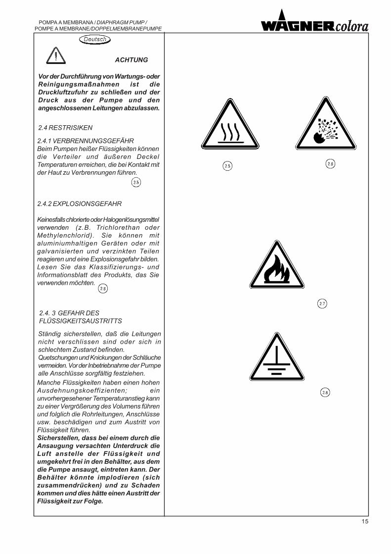
2.4.1 VERBRENNUNGSGEFÄHRBeim Pumpen heißer Flüssigkeiten könnendie Verteiler und äußeren DeckelTemperaturen erreichen, die bei Kontakt mitder Haut zu Verbrennungen führen.
2.4.2 EXPLOSIONSGEFAHR
Keinesfalls chlorierte oder Halogenlösungsmittelverwenden (z.B. Trichlorethan oderMethylenchlorid). Sie können mitaluminiumhaltigen Geräten oder mitgalvanisierten und verzinkten Teilenreagieren und eine Explosionsgefahr bilden.Lesen Sie das Klassifizierungs- undInformationsblatt des Produkts, das Sieverwenden möchten.
2.4. 3 GEFAHR DESFLÜSSIGKEITSAUSTRITTS
Ständig sicherstellen, daß die Leitungennicht verschlissen sind oder sich inschlechtem Zustand befinden.Quetschungen und Knickungen der Schläuchevermeiden. Vor der Inbetriebnahme der Pumpealle Anschlüsse sorgfältig festziehen.
Vor der Durchführung von Wartungs- oderReinigungsmaßnahmen ist dieDruckluftzufuhr zu schließen und derDruck aus der Pumpe und denangeschlossenen Leitungen abzulassen.
ACHTUNG
Manche Flüssigkeiten haben einen hohenAusdehnungskoeffizienten; einunvorhergesehener Temperaturanstieg kannzu einer Vergrößerung des Volumens führenund folglich die Rohrleitungen, Anschlüsseusw. beschädigen und zum Austritt vonFlüssigkeit führen.Sicherstellen, dass bei einem durch dieAnsaugung versachten Unterdruck dieLuft anstelle der Flüssigkeit undumgekehrt frei in den Behälter, aus demdie Pumpe ansaugt, eintreten kann. DerBehälter könnte implodieren (sichzusammendrücken) und zu Schadenkommen und dies hätte einen Austritt derFlüssigkeit zur Folge.
16
POMPA A MEMBRANA / DIAPHRAGM PUMP /POMPE A MEMBRANE/DOPPELMEMBRANEPUMPE
2.5 COMPATIBILITA' CHIMICA DEIMATERIALI
2.5 MATERIAL CHEMICAL COMPATIBILITY
2.5 COMPATIBILITE CHIMIQUE DESMATERIAUX
Vérifier la compatibilité chimique desmatériaux de construction de lapompe avec le fluide que l'on al'intention de pomper. Un choix erronépourrait provoquer, en plus del'endommagement précoce de lapompe et des tuyauteries, desrisques graves pour les personnes(fuite de produits irritants etnéfastespour la santé) et pour lemilieu.En cas de doute, contacter notreService Technique.
Verificare la compatibilità chimica deimateriali, con cui è costruita la pompa,con il fluido che si intende pompare.Una scelta errata potrebbe provocare,oltre al danneggiamento precoce dellapompa e delle tubazioni, gravi rischiper le persone (fuoriuscita di prodottiirritanti e nocivi alla salute) e perI�ambiente.In caso di dubbio interpellare il nostroServizio tecnico.
Make sure the materials employed inmanufacturing the pump arechemically compatible with the fluidyou wish to pump.If you make the wrong choice you riskharming people (as a, result of noxiousand irritant: products outpour) as wellas polluting the environment, besidesprematurely damaging the pump andits hoses.If in doubt, please call our TechnicalService Department.
Un tubo flessibile o un raccordodanneggiati sono PERICOLOSIprovvedere alla loro sostituzione.
2.4.4 RISCHIO RUMOREIn alcune condizioni di funzionamentola rumorosità della pompa potrebbeessere alta; ad esempio con elevatapressione di alimentazione dell�aria diazionamento e bassa o nullapressione del liquido pompato(funzionamento a bocca libera); nelcaso dotare il personale, presente inprossimità della pompa, di opportunidispositivi di protezione individuale,DPI, ed utilizzare valvole e relative sediin materiale plastico se le condizionioperative e la compatibilità, con il fluidopompato, lo consentono.
Non cercare mai di interrompereo deviare eventuali perdite con lemani o altre parti del corpo.
ATTENZIONE
Do not use your hands or otherparts of your body to stop or diverteventual leaks.
Damaged flexible hoses and fittingsare dangerous: replace, themimmediately.
2.4.4 NOISE RISKIn some working conditions, thepump can be particularly noisy: for ex.when the air feeding pressure is highand when there is no pressure or avery low pressure in the pumped liquid(mouth free working); in these cases,all personnel working next to the pumpshall wear adequate individualprotections (DPI) and use valves andseats in plastic material, provided theworking conditions and thecompatibility with the pumped liquidallow it.
WARNING
Ne jamais essayer d'interrompreou de dévier les éventuels fuitesavec les mains ou d'autres partiesdu corps.Un tuyau flexible ou un raccordendommagés sont DANGEREUX.Les remplacer.
2.4.4 RISQUE BRUITDans certains conditions de travail,la pompe pourrait produire un fortbruit; par exemple en cas de hautepression d�alimentation de l�aird�actionnement et pression faible ouabsente du liquide pompé(fonctionnement avec bouche libre) ;dans ces cas, le personnel travaillanten proximité de la pompe doit utiliserdes dispositifs de protectionindividuelle adéquats, DPI, ainsi quede soupapes et des sièges enmatière plastique si les conditions detravail et la comptabilité avec le fluidepompé le permettent.
ATTENTION
Controllare periodicamente il regolarefunzionamento della pompa, ponendoparticolare attenzione alla presenza diaria nel fluido pompato, che può essereprovocata dalla rottura delle membranedella pompa.Evitare di far funzionare la pompa conle membrane danneggiate.
Periodically check that the pump isworking regularly, paying specialattention to presence of air in thepumped fluid, which may be causedby breakage of the pump�smembranes.Avoid operating the pump with itsmembranes damaged.
Contrôler périodiquement lefonctionnement régulier de la pompe,en soignant notamment la présenced�air dans le fluide pompé, qui peutêtre provoquée par la rupture desmembranes de la pompe. Eviter defaire fonctionner la pompe en cas demembranes endommagées.

17
POMPA A MEMBRANA / DIAPHRAGM PUMP / POMPE A MEMBRANE/DOPPELMEMBRANEPUMPE
2.5 CHEMISCHE VERTRÄGLICHKEITDES MATERIALS
Überprüfen Sie die chemische Verträglichkeitdes Materials, aus dem die Pumpe hergestelltwurde, mit der zu pumpenden Flüssigkeit.Eine falsche Kombination könnte über einefrühzeitige Beschädigung der Pumpe undihrer Leitungen hinaus zu schwerenGesundheitsschädigungen (Austrittgesundheitsschädlicher Reizmittel) undGefahren für die Umwelt führen.Im Zweifelsfall wenden Sie sich bitte anunseren Kundendienst.
Niemals versuchen, etwaige Verluste mitden Händen oder anderen Körperteilenaufzuhalten oder umzulenken.
Ein defekter Schlauch oder Anschluß stellteine GEFAHR dar und ist zu ersetzen.
2.4.4 GEFAHREN DUCH HOHESGERÄUSCHNIVEAUUnter manchen Betriebsbedingungen könntedie Pumpe ein hohes Geräuschniveauaufweisen; beispielsweise bei hohem Druckder Betriebsluftspeisung sowie niedrigembzw. nicht vorhandenem Druck dergepumpten Flüssigkeit (Betrieb mit freiemStutzen); in diesem Fall das Personal, dassich in der Nähe der Pumpe aufhält, mitentsprechenden individuellenSchutzvorrichtungen, DPI, ausstatten undVentile sowie entsprechende Gehäuse ausPlastikmaterialien einsetzen, falls dieBetriebsbedingungen und die Kompatibilitätmit der gepumpten Flüssigkeit dieszulassen.
ACHTUNG
Den regulären Betrieb der Pumpe periodischüberprüfen und dabei insbesondere auf dasVorhandensein von Luft in derPumpflüssigkeit achten, die durch eineBeschädigung der Pumpenmembraneeingetreten sein könnte.Die Pumpe nicht mit beschädigtenMembranen betreiben.

18
POMPA A MEMBRANA / DIAPHRAGM PUMP /POMPE A MEMBRANE/DOPPELMEMBRANEPUMPE
E' necessario che il personalefaccia uso dei dispositivi diprotezione, degli indumenti edegli attrezzi, rispondenti allenorme vigenti in relazione alluogo ed all' impiego della pompasia durante il lavoro che nelleoperazioni di manutenzione.
L� apparecchiatura deve essereutilizzata esclusivamente dapersonale opportunamenteformato ed autorizzato.
ATTENZIONE
All personnel must use protections,clothes and tools complying withthe regulations in force, dependingon the working environment andthe use the pump is put to.
WARNING
Only properly trained andauthorised personnel must use theequipment.
Once the pump has been stopped, toprevent harming people and/ordamaging things and the environment,it is best to release the pressure bykeeping the delivery valve open or byresorting to the appropriate exhaustvalve (see "Diagram illustrating thepump functioning").If it is not possible to do so, makesure you adequately report thepresence of pressure inside theequipment.
When using the pump after a longperiod of inactivity, make sure thatall parts subject to pressure hold.
Use only original spare parts.
Il est nécessaire que le personnelutilise des dispositifs de protection,des vêtements et des outilsconformes aux normes en vigueurselon le lieu et l'emploi de lapompe tant pendant le travail quelors des opérations d'entretien.
ATTENTION
Pour éviter les risques de lésion et/ou les dommages aux choses et aumilieu après l'arrêt de la pompe, il estopportun de décharger la pression enmaintenant ouverte l'utilisation ou enagissant sur une soupape dedécharge spécifique.(voir "Schéma de fonctionnementpompe").Si cela n'est pas possible, signalerde façon appropriée la présence depression dans les appareils.
Après de longues périodes d'inactivité,vérifier l'étanchéité de toutes lespièces sujettes à pression.
Utiliser exclusivement des pièces derechange d'origine.
L�équipement ne doit être utiliséque par des opérateurs autoriséset dûment formés.
Per arrestare tempestivamente lapompa chiudere la valvola diintercettazione dell' aria o delregolatore di pressione interrompendocosì l' alimentazione al motore.
Le pompe ad azionamentopneumatico, pur con l' alimentazionedell' aria chiusa, possono mantenerein pressione tutti i componentiallacciati alla mandata.
Per evitare i rischi di lesione e/o dannialle cose ed all'ambiente dopo l'arrestodella pompa è opportuno scaricare lapressione mantenendo aperto l' utilizzoo agendo su un'apposita valvola discarico.(vedi "Schema funzionamentopompa").Se ciò non fosse possibile, segnalarein modo adeguato la presenza dipressione nelle apparecchiature.
Dopo lunghi periodi di inattivitàverificare la tenuta di tutte le partisoggette a pressione.
Usare esclusivamente ricambi originali.
2.6 ARRESTO EMERGENZA
Stop the unit at the right time, closethe air cutoff valve or the pressureregulator; as a consequence of thisthe flow of air feeding the motor willbe interrupted.
Pneumatic pumps can keep allcomponents connected to the deliveryline pressurized, even when the airinput valve is closed.
2.6 EMERGENCY STOP
Les pompes à actionnementpneumatique, même avecl'alimentation de l'air fermée, peuventmaintenir sous pression toutes lespièces reliées au refoulement.
Pour arrêter immédiatement lapompe, fermer la soupape d'arrêt del'air ou du régulateur de pression eninterrompant ainsi l'alimentation aumoteur.
2.6 ARRET D'URGENCE

19
POMPA A MEMBRANA / DIAPHRAGM PUMP / POMPE A MEMBRANE/DOPPELMEMBRANEPUMPE
Zur Vermeidung von Verletzungen und/oderSach- oder Umweltschäden muß nach demStillstand der Pumpe der Druck abgelassenwerden, indem das Druckventil offen zuhalten oder ein spezielles Ablaßventil zubetätigen ist.(siehe Schaubild zur "Funktionsweise derPumpe").Ist dies nicht möglich, muß dasVorhandensein des Drucks in der Anlageangemessen kenntlich gemacht werden.
Nach längeren Phasen des Betriebsstillstandsist die Dichtheit aller Teile, die Druck ausgesetztwerden, zu überprüfen.
Ausschließlich Originalersatzteile verwenden.
Das Gerät darf nur von entsprechendgeschultem und autorisiertem Personalbedient werden.
Das Personal muß sowohl beim Betriebals auch bei Durchführung derWartungsmaßnahmen von denSchutzmitteln, der Kleidung und demWerkzeug Gebrauch machen, die vonden geltenden Vorschriften bezüglich desEinsatzes und des Einsatzortes derPumpe vorgesehen sind.
ACHTUNG
Zum plötzlichen Anhalten der Pumpe ist dasLuftsperrventil des Druckreglers zuschließen, wodurch die Luftversorgung derPumpe unterbrochen wird.
Auch bei geschlossener Luftzufuhr könnenpneumatisch betriebene Pumpen alledruckseitig angeschlossenen Komponentenunter Druck halten.
2.6 NOTSTOPP

20
POMPA A MEMBRANA / DIAPHRAGM PUMP /POMPE A MEMBRANE/DOPPELMEMBRANEPUMPE
Se l� apparecchiatura deve operarecon solventi o prodotti chimici cheproducono emissioni nell� atmosfera,assicurarsi che l� ambiente sia dotatodi adeguati sistemi di aspirazione edabbattimento vapori e/o fumi,rispondenti alle norme vigenti.
Le pompe standard non sono adatteper prodotti alimentari.
L' idoneità all' impiego con prodottialimentari è indicata dalla nota"Pompa adatta per alimenti".
L'utilizzatore deve controllareperiodicamente, in funzione del tipodi utilizzo e delle sostanze impiegate,la presenza di incrostazioni, lapulizia, lo stato di usura deicomponenti ed il correttofunzionamento del gruppo pompa.L'operazione deve essere effettuata infase di manutenzione in accordo daquanto previsto dal manuale.
If the equipment must operate withsolvents or chemical products thatproduce emissions in theatmosphere, make sure that theenvironment is equipped with theappropriate vapour and/or fumesuction and damping systems thatcomply with the regulations in force.
Standard pumps are not suitable tohandle food.
A note saying "Pump suitable for food"indicates that the pump may be usedto handle food.
Depending on the type of use and thesubstances used, the user has toperiodically check for presence ofdeposits as well as its cleanliness, thestate of wear of the components andproper operation of the pumpassembly.The operation has to be carried outduring maintenance in conformity withwhat is written in the manual.
Si l�équipement doit utiliser dessolvants ou des produits chimiquesproduisant des émissions dansl�atmosphère, vérifier que le milieu soitpourvu d�un système adéquatd�aspiration et de neutralisation devapeurs et/ou de fumées,conformément aux normes en vigueur.
Les pompes standard ne sont pasappropriées pour les produitsalimentaires.
L'aptitude à l'emploi avec des produitsalimentaires est indiquée dans laremarque "Pompe appropriée pouraliments".
L�utilisateur doit contrôlerpériodiquement, en fonction du typed�utilisation et des substancesutilisées, la présence d�incrustations,la propreté, l�état d�usure descomposants ainsi que lefonctionnement correct du groupepompe.L�opération doit être effectuée pendantla phase d�entretien, conformémentaux instructions contenues dans lemanuel.

21
POMPA A MEMBRANA / DIAPHRAGM PUMP / POMPE A MEMBRANE/DOPPELMEMBRANEPUMPE
Sollte das Gerät mit Lösungsmitteln oderchemischen Substanzen betrieben werden,durch die Emissionen in die Atmosphäreabgegeben werden, sicherstellen, dass dieUmgebung mit entsprechenden Ansaug-und Abbausystemen von Dämpfen und/oderAbgasen gemäß der geltenden Vorschriftenausgestattet ist.
Standardpumpen sind für Lebensmittelungeeignet.
Eine für den Einsatz mit Lebensmittelngeeignete Pumpe ist durch den Hinweis"Pumpe für Lebensmittel geeignet"gekennzeichnet.
Der Betreiber wird aufgefordert, dasVorhandensein von Verkrustungen, denVerschleißzustand sowie den korrektenBetrieb der Pumpeinheit je nachVerwendungsart und Flüssigkeit periodischzu überprüfen.Dieser Vorgang ist während derWartungsarbeiten in Übereinstimmung mitden Angaben der Betriebsanleitungdurchzuführen.

22
POMPA A MEMBRANA / DIAPHRAGM PUMP /POMPE A MEMBRANE/DOPPELMEMBRANEPUMPE
2.7 ISTRUZIONI DI SICUREZZA
Per l'utilizzo in ambienti con pericolodi esplosione.
PREMESSA
Queste istruzioni di sicurezza siriferiscono all�installazione, uso emanutenzione della pompa per utilizzoin aree con presenza di atmosferepotenzialmente esplosive.La pompa oggetto delle presentiistruzioni e� dotata delle seguentiprotezioni contro il rischio diesplosione:
N.B.Queste istruzioni devono essereosservate in aggiunta alle avvertenzegenerali di sicurezzaprecedentemente riportate.
2.7.1 INSTALLAZIONE
Idoneità della pompa al luogo diinstallazioneNel caso di utilizzo in aree con pericolodi esplosione si deve verificare che lapompa sia idonea alla classificazionedella zona ed alle caratteristiche dellesostanze infiammabili presentisull�impianto.I requisiti essenziali di sicurezzacontro il rischio di esplosione nellearee classificate sono fissati dalledirettive europee 94/9/CE del 23marzo 1994 (per quanto riguarda leapparecchiature) e 1999/92/CE del 16Dicembre 1999 (per quanto riguardagli impianti).I criteri per la classificazione delle areecon rischio di esplosione sono datidalla norma EN 60079-10.I requisiti tecnici degli impianti elettricinelle aree classificate sono dati dallanorma EN 60079-14.
II 2G II B T4+4°C Tamb +40°C
2.7 SAFETY INSTRUCTIONS
For use in environments with dangerof explosion.
INTRODUCTION
These safety instructions refer to theinstallation, use and maintenance ofthe pump for use in areas withpresence of potentially explosiveatmospheres.The pump that these instructions referto is equipped with the followingprotections against the risk ofexplosion:
NOTEThese instructions must be compliedwith in addition to the general safetywarnings previously given.
2.7.1 INSTALLATION
Suitability of the pump for the placeof installationIf it is used in areas with danger ofexplosion, you have to verify that thepump is suitable for the area�sclassification and for thecharacteristics of the flammablesubstances present on the plant.The essential safety requirements toprevent risk of explosion in theclassified areas are set out inEuropean directives 94/9/EC of 23March 1994 (regarding the equipment)and 1999/92/EC of 16 December 1999(regarding the plants).The criteria for classifying the areaswith risk of explosion are given in theEN 60079-10 standard.The technical requisites of the electricinstallations in the classified areas aregiven in the EN 60079-14 standard.
2.7 INSTRUCTIONS DE SECURITE
Pour l�emploi dans des zones à risqued�explosion
PREMISSE
Ces instructions de sécurité se réfèrentà l�installation, l�emploi et l�entretiende la pompe dans des zones enprésence d�une atmosphèrepotentiellement explosive.La pompe qui est l�objet de cesinstructions est pourvue desprotections suivantes contre le risqued�explosion
N.B.Ces instructions doivent êtreobservées en complètement desavertissements généraux de sécuritéprécédemment mentionnés
2.7.1 INSTALLATION
Aptitude de la pompe au lieud�installationEn cas d�utilisation dans des zones àrisque d�explosion, on doit vérifier quela pompe est apte à la classificationde la zone et aux caractéristiques dessubstances inflammables présentesdans l�installation.Les caractéristiques essentielles desécurité contre le risque d�explosiondans les zones classifiées ont étéfixées par les directives européennes94/9/CE du 23 mars 1994 (en matièredes équipements) et 1999/92/CE du16 décembre (en matièresd�installations)Les critères de classification deszones à risque d�explosion sontspécifiés par la norme EN 60079-10.Les caractéristiques techniques desinstallations électriques dans lezzones classifiées sont fixées par lanorme EN 60079-14.
II 2G II B T4+4°C Tamb +40°C
II 2G II B T4+4°C Tamb +40°C
23
POMPA A MEMBRANA / DIAPHRAGM PUMP / POMPE A MEMBRANE/DOPPELMEMBRANEPUMPE
2.7 SICHERHEITSANWEISUNGEN
Zur Verwendung in Umgebungen mitExplosionsgefahr.
VORAUSSETZUNG
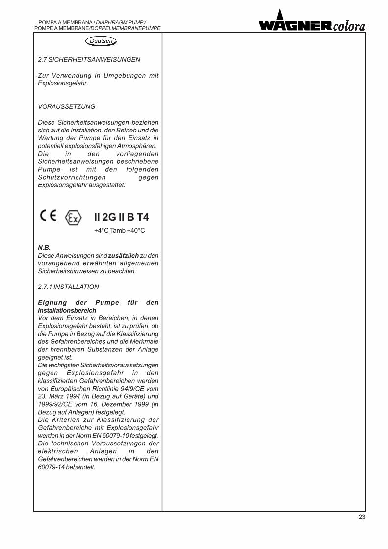
Diese Sicherheitsanweisungen beziehensich auf die Installation, den Betrieb und dieWartung der Pumpe für den Einsatz inpotentiell explosionsfähigen Atmosphären.Die in den vorliegendenSicherheitsanweisungen beschriebenePumpe ist mit den folgendenSchutzvorrichtungen gegenExplosionsgefahr ausgestattet:
N.B.Diese Anweisungen sind zusätzlich zu denvorangehend erwähnten allgemeinenSicherheitshinweisen zu beachten.
2.7.1 INSTALLATION
Eignung der Pumpe für denInstallationsbereichVor dem Einsatz in Bereichen, in denenExplosionsgefahr besteht, ist zu prüfen, obdie Pumpe in Bezug auf die Klassifizierungdes Gefahrenbereiches und die Merkmaleder brennbaren Substanzen der Anlagegeeignet ist.Die wichtigsten Sicherheitsvoraussetzungengegen Explosionsgefahr in denklassifizierten Gefahrenbereichen werdenvon Europäischen Richtlinie 94/9/CE vom23. März 1994 (in Bezug auf Geräte) und1999/92/CE vom 16. Dezember 1999 (inBezug auf Anlagen) festgelegt.Die Kriterien zur Klassifizierung derGefahrenbereiche mit Explosionsgefahrwerden in der Norm EN 60079-10 festgelegt.Die technischen Voraussetzungen derelektrischen Anlagen in denGefahrenbereichen werden in der Norm EN60079-14 behandelt.
II 2G II B T4+4°C Tamb +40°C

24
POMPA A MEMBRANA / DIAPHRAGM PUMP /POMPE A MEMBRANE/DOPPELMEMBRANEPUMPE
In base a queste disposizioni tecnichee legislative la scelta del tipo di pompadeve tenere conto dei seguenti fattori:- tipo di impianto: miniere ( gruppo
I ), impianti di superficie ( gruppoII )
- classificazione della zona: 0, 1, 2(per le quali sono idoneeapparecchiature rispettivamente dicategoria 1, 2, 3)
- caratteristiche delle sostanzeinfiammabili presenti sotto formadi gas, vapori o nebbie:
- classe di temperatura: T1, T2, T3,T4, T5, T6 (definisce latemperatura di accensione deigas)
2.7.2 DATI DI TARGA RIGUARDANTILA SICUREZZA
I dati riportati in targa contengono, oltreai dati funzionali, le informazioninecessarie per la verifica dell�idoneitàdella pompa per una determinata zonaper la sua corretta installazione.
II 2 G
Marcatura di conformità alladirettiva 94/9/CE ed allerelative norme tecniche.
Pompa per impianti disuperficie con presenza digas o vapori, di categoria 2,idoneo per zona 1 e (conridondanza) per zona 2.
Marcatura di conformità alledirettive europee applicabili.
Codice del fascicolo tecnicoredatto e conservato inconformità allaDirettiva 94/9/CE
TF01PM/ATEX
T4 Classe di temperatura - Maxtemperatura superficiale:135°C
Sur la base de ces dispositionstechniques et législatives, le choix dutype de pompe doit tenir compte desfacteurs suivants :- type d�installation: mines (groupe
I), installations de surface (groupeII)
- classification de la zone: 0, 1, 2(pour lesquelles l�on considèreaptes les équipementsrespectivement de catégorie 1, 2,3)
- caractéristiques des substancesinflammables présentes sousforme de gaz, vapeur
- classe de température: T1, T2, T3,T4, T5, T6 (cela définit latempérature d�inflammation desgaz)
2.7.2 DONNEES DE PLAQUE ENMATIERE DE SECURITEEn plus des données fonctionnelles,les données indiquées sur la plaquecontiennent les informationsnécessaires pour vérifier l�aptitude dela pompe dans une zone déterminée,pour une installation correcte.
II 2 G
T4
TF01PM/ATEX
Marquage conformémentà la directive 94/9/CE etaux normes techniques
Pompe pour installation desurface en présence degaz ou vapeur, decatégorie 2, apte pourzone 1 et (avecredondance) pour zone 2
Marquage conformémentaux directives européennesapplicables
Classe de température -Max températuresuperficielle: 135°C
Code du dossier techniquerédigé et conservéconformément à laDirective 94/9/CE
Based on these technical andlegislative provisions, choice of thetype of pump must bear in mind thefollowing factors:- type of plant: mine (group I),
surface plants (group II)- classification of the area: 0, 1, 2
(for which equipment of categories1, 2 and 3, respectively, aresuitable)
- characteristics of the flammablesubstances present in the formof gas, vapours or mists:
- temperature classes: T1, T2, T3,T4, T5, T6 (defines the ignitiontemperature of the gases)
2.7.2 RATING PLATE DATAREGARDING SAFETY
In addition to the functional data, thedata shown on the plate contain theinformation necessary for verifying thepump�s suitability for a given area forits proper installation.
Mark showing compliancewith directive 94/9/EC andthe other relative technicalstandards.
II 2 G Pump for surface plantswith presence of gas orvapours, category 2,suitable for area 1 and (withredundancy) for area 2.
Mark showing compliancewith the applicable Europeandirectives.
T4 Temperature class � Maxsurface temperature: 135°C
TF01PM/ATEXCode of the technical file drawn up andstored in conformity with directive 94/9/EC

25
POMPA A MEMBRANA / DIAPHRAGM PUMP / POMPE A MEMBRANE/DOPPELMEMBRANEPUMPE
Unter Berufung auf diese technischen undgesetzlichen Vorgaben sind bei der Wahldes Pumpentyps folgende Faktoren zuberücksichtigen:- Anlagentyp: Schachtanlage (Gruppe I),
Oberflächenanlagen (Gruppe II)- Klassifizierung der Gefahrenzone: 0, 1,
2 (hierfür sind Geräte mit denentsprechenden Kategorien 1,2, 3geeignet)
- Eigenschaften der brennbaren Stoffe inForm von Gas, Dampf oder Nebel:
- Temperaturklasse: T1, T2, T3, T4, T5,T6 (definiert die Entzündungstemperaturder Gase)
2.7.2 SICHERHEITSDATEN AUF DEMTYPENSCHILDDie auf dem Typenschild genannten Datenumfassen neben den Betriebsdaten alleerforderlichen Informationen, um zuerkennen, ob eine Pumpe für einenbestimmten Bereich geeignet ist und dortinstalliert werden kann.
Konformitätshinweis gemäßRichtlinie 94/9/CE undentsprechende technischeNormen
II 2 G
T4
TF01PM/ATEX
Pumpe für Oberflächenanlagemit Gasen oder Dampf,Kategorie 2, geeignet für Zone1 und (mit Mehrfachausrüstung)Zone 2.
Konformitätshinweis gemäß deranwendbaren europäischenRichtlinien.
Temperaturklasse - MaximaleOberflächentemperatur: 135°C
Code des technischen Berichts,der gemäß Richtlinie 94/9/CEerstellt und aufbewahrt wird.
26
POMPA A MEMBRANA / DIAPHRAGM PUMP /POMPE A MEMBRANE/DOPPELMEMBRANEPUMPE
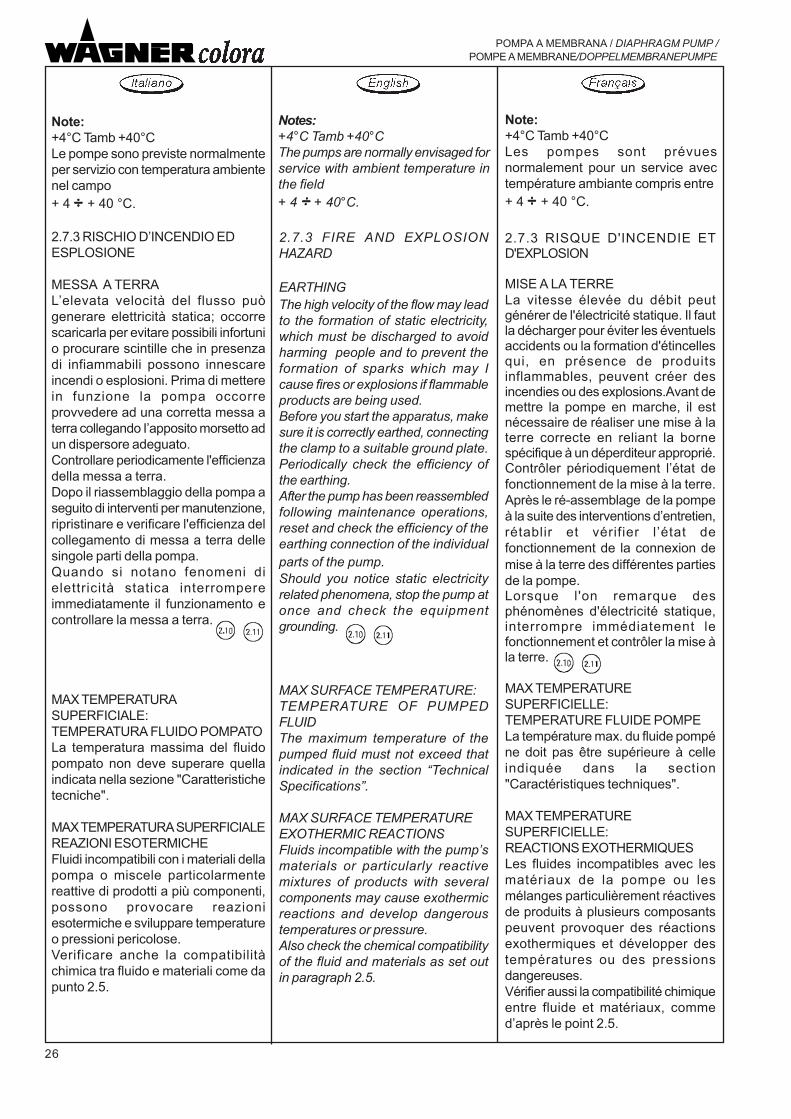
Note:+4°C Tamb +40°CLe pompe sono previste normalmenteper servizio con temperatura ambientenel campo+ 4 ÷÷÷÷÷ + 40 °C.
2.7.3 RISCHIO D�INCENDIO EDESPLOSIONE
MESSA A TERRAL�elevata velocità del flusso puògenerare elettricità statica; occorrescaricarla per evitare possibili infortunio procurare scintille che in presenzadi infiammabili possono innescareincendi o esplosioni. Prima di metterein funzione la pompa occorreprovvedere ad una corretta messa aterra collegando I�apposito morsetto adun dispersore adeguato.Controllare periodicamente l'efficienzadella messa a terra.Dopo il riassemblaggio della pompa aseguito di interventi per manutenzione,ripristinare e verificare l'efficienza delcollegamento di messa a terra dellesingole parti della pompa.Quando si notano fenomeni dielettricità statica interrompereimmediatamente il funzionamento econtrollare la messa a terra.
MAX TEMPERATURASUPERFICIALE:TEMPERATURA FLUIDO POMPATOLa temperatura massima del fluidopompato non deve superare quellaindicata nella sezione "Caratteristichetecniche".
MAX TEMPERATURA SUPERFICIALEREAZIONI ESOTERMICHEFluidi incompatibili con i materiali dellapompa o miscele particolarmentereattive di prodotti a più componenti,possono provocare reazioniesotermiche e sviluppare temperatureo pressioni pericolose.Verificare anche la compatibilitàchimica tra fluido e materiali come dapunto 2.5.
2.7.3 FIRE AND EXPLOSIONHAZARD
EARTHINGThe high velocity of the flow may leadto the formation of static electricity,which must be discharged to avoidharming people and to prevent theformation of sparks which may Icause fires or explosions if flammableproducts are being used.Before you start the apparatus, makesure it is correctly earthed, connectingthe clamp to a suitable ground plate.Periodically check the efficiency ofthe earthing.After the pump has been reassembledfollowing maintenance operations,reset and check the efficiency of theearthing connection of the individualparts of the pump.Should you notice static electricityrelated phenomena, stop the pump atonce and check the equipmentgrounding.
MAX SURFACE TEMPERATURE:TEMPERATURE OF PUMPEDFLUIDThe maximum temperature of thepumped fluid must not exceed thatindicated in the section �TechnicalSpecifications�.
MAX SURFACE TEMPERATUREEXOTHERMIC REACTIONSFluids incompatible with the pump�smaterials or particularly reactivemixtures of products with severalcomponents may cause exothermicreactions and develop dangeroustemperatures or pressure.Also check the chemical compatibilityof the fluid and materials as set outin paragraph 2.5.
2.7.3 RISQUE D'INCENDIE ETD'EXPLOSION
MISE A LA TERRELa vitesse élevée du débit peutgénérer de l'électricité statique. Il fautla décharger pour éviter les éventuelsaccidents ou la formation d'étincellesqui, en présence de produitsinflammables, peuvent créer desincendies ou des explosions.Avant demettre la pompe en marche, il estnécessaire de réaliser une mise à laterre correcte en reliant la bornespécifique à un déperditeur approprié.Contrôler périodiquement l�état defonctionnement de la mise à la terre.Après le ré-assemblage de la pompeà la suite des interventions d�entretien,rétablir et vérifier l�état defonctionnement de la connexion demise à la terre des différentes partiesde la pompe.Lorsque l'on remarque desphénomènes d'électricité statique,interrompre immédiatement lefonctionnement et contrôler la mise àla terre.
MAX TEMPERATURESUPERFICIELLE:TEMPERATURE FLUIDE POMPELa température max. du fluide pompéne doit pas être supérieure à celleindiquée dans la section"Caractéristiques techniques".
MAX TEMPERATURESUPERFICIELLE:REACTIONS EXOTHERMIQUESLes fluides incompatibles avec lesmatériaux de la pompe ou lesmélanges particulièrement réactivesde produits à plusieurs composantspeuvent provoquer des réactionsexothermiques et développer destempératures ou des pressionsdangereuses.Vérifier aussi la compatibilité chimiqueentre fluide et matériaux, commed�après le point 2.5.
Note:+4°C Tamb +40°CLes pompes sont prévuesnormalement pour un service avectempérature ambiante compris entre+ 4 ÷÷÷÷÷ + 40 °C.
Notes:+4°C Tamb +40°CThe pumps are normally envisaged forservice with ambient temperature inthe field+ 4 ÷÷÷÷÷ + 40°C.

27
POMPA A MEMBRANA / DIAPHRAGM PUMP / POMPE A MEMBRANE/DOPPELMEMBRANEPUMPE
2.7.3 BRAND- UNDEXPLOSIONSGEFAHR
ERDUNGDie hohe Fließgeschwindigkeit kann einestatische Aufladung erzeugen. ZurVermeidung von Unfällen oder Funkenflug,der bei Anwesenheit von entflammbarenStoffen Brände oder Explosionen auslösenkann, ist diese Ladung abzubauen. Vor derInbetriebnahme der Pumpe ist für eineordnungsgemäße Erdung zu sorgen.Schließen sie hierzu die spezielle Klemmean einen geeigneten Erdanschluß an.Die Erdung periodisch überprüfen.Nach der Wiedermontage der Pumpe nachWartungsarbeiten, den Erdungsanschlussder einzelnen Pumpenteile wiederherstellenund kontrollieren.Bemerken Sie Anzeichen von statischerAufladung, ist der Betrieb unverzüglich zuunterbrechen und die Erdung zukontrollieren.
MAXIMALEOBERFLÄCHENTEMPERATUR:TEMPERATUR PUMPFLÜSSIGKEITDie maximale Temperatur derPumpflüssigkeit darf nicht über dem imAbschnitt �Technische Eigenschaften�genannten Wert liegen.
MAXIMALEOBERFLÄCHENTEMPERATUR:EXOTHERME REAKTIONENFlüssigkeiten, die mit denPumpenmaterialien nicht kompatibel sindoder besonders reaktive Mischungen ausverschiedenen Komponenten könnenexotherme Reaktionen hervorrufen und hoheTemperaturen oder gefährliche Druckwerteentwickeln.Prüfen Sie auch die chemischeKompatibilität zwischen Flüssigkeit undMaterialien gemäß Punkt 2.5.
Anmerkungen:+4°C Tamb +40°CDie Pumpen sind für den normalen Betriebbei einer Raumtemperatur von + 4 ÷÷÷÷÷ + 40°C vorgesehen.

28
POMPA A MEMBRANA / DIAPHRAGM PUMP /POMPE A MEMBRANE/DOPPELMEMBRANEPUMPE
ATTENZIONE
Per pompe installate in zone conpericolo di esplosione, le tubazionidevono essere in materiale conduttivoe collegate a terra.
Provvedere all'installazione di un filtrosul circuito di aspirazione, al fine dievitare la presenza di corpi solidi didimensioni tali da danneggiare le partiinterne della pompa. Riferirsi alparagrafo "Caratteristiche Tecniche" perle massime dimensioni di solidipompabili.
Mantenere pulite le superfici metalliche.La conduttività elettrica delle superficicostituisce un componente del mododi protezione.Pulire frequentemente l'apparecchiaturaper evitare l'accumulo di residui disostanze isolanti.
Evitare l'impiego di parti arrugginite odi utensili metallici che possonoprovocare scintille di origine meccanicaall'interno della zona con pericolo diesplosione.
Con l'utilizzo di liquidi infiammabili,evitare per quanto possibile di farfunzionare la pompa a vuoto, perlimitare le probabilità di formazione diatmosfera esplosiva all'interno dellapompa.
ATTENTION
En cas de pompes installées dansdes zones à risque d�explosion, lestuyaux doivent être en matérielconductible et connectés à la terre.
Installer un filtre sur le circuitd�aspiration afin d�éviter la présencede corps solides dont les dimensionspourraient endommager les partiesintérieures de la pompe. Faireréférence au paragraphe« Caractéristiques techniques » pourles dimensions max. de solides àpomper.
Les surfaces métalliques doivent êtretoujours propres. La conductivitéélectrique des surfaces représente uncomposant dans le mode deprotection.Nettoyer fréquemment l�équipementpour éviter l�accumulation de résidusde substances isolantes.
Eviter l�utilisation de parties rouilléesou d�outils métalliques pouvantprovoquer d�étincelles d�originemécanique dans la zone à risqued�explosion.
Si l�on utilise des liquidesinflammables, éviter en tant quepossible le fonctionnement à vide dela pompe, pour limiter les probabilitésde formation d�atmosphère explosiveà l�intérieur de la pompe.
CAUTION
For pumps installed in areas with riskof explosion, pipes shall be inconductive material and connected toearth.
Install a filter on the intake circuit inorder to prevent solid bodies of sucha size that would damage the internalparts of the pump from entering.Refer to the paragraph �TechnicalSpecifications� to get the maximumsize of the solids that can bepumped.
Keep the metal surfaces clean.Electric conductivity of the surfacesis one component that contributes toprotection.Frequently clean the equipment so asto prevent residue of insulatingsubstances from accumulating.
Avoid using rusted parts or metaltools that may cause sparks of amechanical origin inside the area withdanger of explosion.
When using flammable liquids, avoididling the pump as much as possibleso as to limit the probability of anexplosive atmosphere from forminginside the pump.

29
POMPA A MEMBRANA / DIAPHRAGM PUMP / POMPE A MEMBRANE/DOPPELMEMBRANEPUMPE
ACHTUNG
Bei Pumpen die in Umgebungen mitExplosionsgefahr installiert sind, müssen dieRohrleitungen aus leitfähigem Materialbestehen und geerdet sein.
Bei der Installation einen Filter auf demAnsaugkreislauf vorsehen, um das Eintretenvon Feststoffen zu vermeiden, die dasPumpeninnere beschädigen könnten.Konsultieren Sie den Abschnitt �TechnischeEigenschaften� zur Ermittlung der maximalenAbmessungen von pumpfähigenFeststoffen.
Die Metalloberflächen sauber halten. Dieelektrische Leitfähigkeit der Oberflächenstellt ein Bestandteil des Schutzes dar.Das Gerät häufig reinigen, um das Anhäufenvon isolierenden Reststoffen zu vermeiden.
Den Einsatz von verrosteten Teilen oderMetallwerkzeugen vermeiden, diemechanisch verursachte Funken innerhalbdes explosionsfähigen Gefahrenbereichesverursachen könnten.
Bei Verwendung von entzündbarerFlüssigkeit möglichst vermeiden, die Pumpeleer zu betrieben, um die Wahrscheinlichkeiteiner explosionsfähigen Atmosphäre in derPumpe zu beschränken.

30
POMPA A MEMBRANA / DIAPHRAGM PUMP /POMPE A MEMBRANE/DOPPELMEMBRANEPUMPE
3. DESCRIZIONE DELLAMACCHINA E DATI TECNICI
3. MACHINE DESCRIPTIONAND TECHNICALSPECIFICATIONS
3. DESCRIPTION DE LAMACHINE ET DONNEESTECHNIQUES
Par rapport aux pompes traditionnellescentrifuges ou volumétriques, la pompepneumatique offre une polyvalenceextrême d'emploi: en effet, une variationdes caractéristiques physiques duliquide (viscosité) ou des exigences deprocédé (variation du débit) peut êtreajustée simplement en réglant lapression de l'air d'alimentation. Dans lespompes pneumatiques, l'absorption depuissance est étroitement liée au débitet à la hauteur d'élévation de la pompe:en réduisant le débit, l'absorptiond'énergie se réduit automatiquement.A débit zéro correspond une absorptionzéro.
La pompa pneumatica ha il notevolevantaggio, rispetto alle tradizionali siacentrifughe che volumetriche,dell�estrema versatilità d�impiego:infatti una variazione dellecaratteristiche fisiche del liquido(viscosità) o delle esigenze diprocesso (variazioni della portata),possono essere superate con lasemplice regolazione della pressionedell�aria di alimentazione. Nellepompe pneumatiche I�assorbimentodi potenza è strettamente correlatoalla portata ed alla prevalenza dellapompa: riducendo la portataautomaticamente si riduceI�assorbimento di energia, a portatazero I�assorbimento è zero.
A pneumatic pump, compared totraditional centrifugal and, positive-displacement pumps, has theadvantage of being extremely versatilein its use. Such a pump allows you todeal with changes concerning theliquid physical characteristics (i.e.: itsviscosity) or the processing needs(i.e.: delivery related changes) bysimply adjusting the input air pressure.In pneumatic pumps the power inputvaries depending on the delivery andthe pump head: if you reduce thedelivery the energy input willautomatically decrease.When there is no, delivery the powerinput is nought.
3.1 DESCRIZIONE DEL PRINCIPIODI FUNZIONAMENTO DELLAPOMPA
II principio di funzionamento dellepompe a membrana azionate ad ariacompressa è tanto semplice quantoefficace: due membrane (A), solidalitra loro per mezzo dell�albero digiunzione (B), separano duecapacità contigue in quattro camere.Le interne assolvono la funzione dicamere motrici (M), le esterne dicamere di pompaggio (P).Un distributore pneumaticoconvoglia I�aria compressaalternativamente nell�una o nell�altracamera motrice provocando lospostamento delle membrane ed ilconseguente svuotamento di unacamera pompante (per riduzione divolume) ed il contemporaneoriempimento dell�altra (per aumentodi volume); una serie di valvole diritegno (C) evita il riflusso del liquido,determinando le fasi di aspirazionee mandata in ciascuna camera dipompaggio.
3.1 PUMP OPERATINGPRINCIPLE
3.1 DESCRIPTION DU PRINCIPEDE FONCTIONNEMENTDE LA POMPE
Le principe de fonctionnement despompes à membrane actionnées à aircomprimé est aussi simplequ'efficace: deux membranes (A),solidaires entre elles au moyen del'arbre de jonction (B), séparent deuxcapacités contiguës en quatrechambres; celles intérieures serventde chambres motrices (M), cellesextérieures de chambres de pompage(P). Un distributeur pneumatiqueconvoie l'air comprimé alternativementvers l'une ou l'autre chambre motriceen provoquant le déplacement desmembranes et le vidage conséquentd'une chambre de pompage (parréduction de volume) et le remplissagesimultané de l'autre (par augmentationde volume). Une série de clapets anti-retour (C) évite le reflux du liquide endéterminant les phases d'aspirationet de refoulement dans chaquechambre de pompage.
The principle lying behind thefunctioning of diaphragm pumpsdriven by compressed air is just assimple as it is effective.Two diaphragms (A), which areconnected to one another by meansof a connecting shaft (B) so as to beintegral, divide two adjacentcapacities into four chambers.The inner ones function as drivingchambers (M) while the outer onesfunction as pumping, chambers (P).A pneumatic distributor alternatelyconveys compressed air into one ofthe driving chambers, thus producingthe diaphragms movement andconsequently causing one of thepumping chambers to empty (as aresult of volume decrease), while atthe same time the other fills up (as aresult of volume increase).A series of check valves (C) preventsthe liquid from flowing back, thusproducing the suction and deliveryphases in each pumping chamber.

31
POMPA A MEMBRANA / DIAPHRAGM PUMP / POMPE A MEMBRANE/DOPPELMEMBRANEPUMPE
3.1 BESCHREIBUNG DESFUNKTIONSPRINZIPS DER PUMPE
Das Funktionsprinzip einer druckluftbetriebenenMembranpumpe ist ebenso einfach wiewirksam: Zwei Membranen (A), die durch eineWelle (B) fest miteinander verbunden sind,trennen zwei benachbarte Räume in vierKammern. Die Inneren fungieren alsAntriebskammern (M) und die Äußeren alsPumpkammern (P). Ein Druckluftverteilerleitet die Druckluft abwechselnd in die eineoder die andere Antriebskammer und bewirktso die Verschiebung der Membranen undfolglich die Entleerung einer Pumpkammer(durch Verringerung des Volumens) und dieFüllung der anderen (durch Vergrößerung desVolumens). Eine Reihe vonRückschlagventilen (C) verhindert denRückfluß der Flüssigkeit und bestimmt denSaug- und Pumptakt in beidenPumpkammern.
Die Druckluftpumpe hat gegenüberden herkömmlichen Kreisel- oderVerdrängerpumpen den großen Vorteil, daßsie besonders vielseitig einsetzbar sind. EineÄnderung der physikalischen Eigenschaftder Flüssigkeit (Viskosität) oder derBetriebsanforderungen (Fördermenge) läßtsich einfach durch die Regulierung desVersorgungsdrucks handhaben. Beipneumatischen Pumpen ist dieLeistungsaufnahme eng an Fördermengeund Förderhöhe der Pumpe gebunden: DurchVerringerung der Fördermenge wirdautomatisch die Leistungsaufnahmeherabgesetzt. Bei Fördermenge gleich Nullbesteht auch keine Leistungsaufnahme.
3. BESCHREIBUNG DERMASCHINE UND TECHNISCHEDATEN
M MB
A A
PP
C
C
C
C

32
POMPA A MEMBRANA / DIAPHRAGM PUMP /POMPE A MEMBRANE/DOPPELMEMBRANEPUMPE
Unlike what happens in models drivenmechanically by an electric orcombustion engine, in a pneumaticpump the diaphragm is not subjectedto considerable stress and is alwaysin a situation of equilibrium sincewhatever force is exherted by thecompressed air on the total surfaceof one of its sides, is balanced by anequal force exherted by the liquid onthe other side.
Contrariamente a quanto avviene nelleversioni azionate meccanicamente damotore elettrico od a combustione,nella pompa pneumatica la membrananon è sottoposta a sforzi rilevanti e sitrova costantemente in condizione disostanziale equilibrio in quanto allaspinta dell�aria compressa agente sututta la superficie di un lato,corrisponde una reazione di pari valoreda parte del liquido sul lato opposto.
A diaphragm pump is self-priming,does not need to have its hoses initiallyfilled up.
Many models can be installed withoutparticular devices in environmentssubject to the risk of explosion aslong as they comply with the specificregulations relating the area at risk.
La pompa a membrana èautoadescante, non richiederiempimento iniziale delle tubazioni.
Molti modelli possono essere installatisenza particolari accorgimenti inambienti soggetti al rischio diesplosione a condizione che venganorispettate le norme specifiche relativealla zona di rischio.
Contrairement à ce qui se passe dansles versions actionnéesmécaniquement par moteur électriqueou à combustion, dans la pompepneumatique la membrane n'est passoumise à des efforts importants etse trouve constamment en conditiond'équilibre substantiel étant donnéqu'à la poussée de l'air compriméagissant sur toute la surface d'un côtécorrespond une réaction de mêmevaleur de la part du liquide sur le côtéopposé.
La pompe à membrane est auto-amorçante et ne nécessite pas leremplissage initial des tuyauteries.
Plusieurs modèles peuvent êtreinstallés sans aucune précautionparticulière dans des milieux sujetsau risque d�explosion, pourvu que lesnormes spécifiques relatives à la zoneà risque soient respectées.

33
POMPA A MEMBRANA / DIAPHRAGM PUMP / POMPE A MEMBRANE/DOPPELMEMBRANEPUMPE
Im Gegensatz zu mechanisch durch E-Motoroder Verbrennungsmotor angetriebenePumpen wird die Membran bei derpneumatischen Version keinen größerenBeanspruchungen ausgesetzt und befindetsich ständig in einem Gleichgewichtszustand,da die Kraft durch die Druckluft, die auf diegesamte Oberfläche der einen Seite wirkt,durch eine entsprechende Reaktion derFlüssigkeit auf der anderen Seite ausgeglichenwird.
Viele Modelle können ohne besondereVorkehrungen in Umgebungen mitExplosionsgefahr installiert werden, wenn dieentsprechenden Vorschriften in Bezug aufdie Gefahrenbereiche beachtet werden.
Eine Membranpumpe ist selbstansaugend underfordert keine anfängliche Leitungsfüllung.

34
POMPA A MEMBRANA / DIAPHRAGM PUMP /POMPE A MEMBRANE/DOPPELMEMBRANEPUMPE
3.2 CARATTERISTICHE TECNICHE 3.2 CARACTERISTIQUES TECNIQUES3.2 TECHNICAL FEATURES 3.2 TECHNISCHE MERKMALE
Caratteris tiche tecniche MODELLO PM / PM MODEL Caractéris tiquesFeatures MODELE PM / PM MODEL Merkmale
Alluminio InoxAluminium ZIP 182 Stainl.steelAluminium Edelstahl
Pressione alimentazione aria 1-8 (15-116) bar (psi) 1-8 (15-116)Air feeding pressurePressione mass ima fluido 8 (116) bar (psi) 8 (116)Fluid max. pressure Maximaler Fluessigk eitsdruckPortata mass ima fluido 182 l/min (Gpm) 182 Débit max. fluide Fluid max. flow rate Massima altezza aspirazione (1) 6,3 m 6,3 Hauteur max. d'aspiration (1)Suction max. height (1) Maximale Ansaughoehe (1)Dimensioni massime corpi solidi 3,5 mm 3,5 Dimensions max. corps solides Solid bodies max. size Maximale FeststoffgroessePressione sonora equivalente a 50 cicli/min alimentaz. aria 5 bar (2) 78 dBA 78 alimentat. 5 bar (2)Sound pressure equivalent to 50 cycles/min Entsprechender Schalldr. bei 50 Zyk len/Min.feeding 5 bar (2) Speisung 5 bar (2)Potenza sonora alla portata maxalimentaz. aria 6 bar (3) 87 dBA 87 alimentat. 6 bar (3)Sound power at max. flow rate feeding 6 bar (3) Speisung 6 bar (3)Temperatura fluido pompato (4) 4-90 (39-176) °C (°F) 4-90 (39-176) Température fluide pompé (4)Pumped fluid temperature (4) Temperatur der gepumpten Flüssigkeit (4)Attacco aria compressa 1/2" BSP 1/2" Prise air compriméCompressed air connection DruckluftanschlussAttacchi fluido 1" BSP 1" Prise fluideFluid connections FluessigkeitsanschluesseMassa a secco 12,5 Kg 19Dry mass Quota A 307 307 CotesDimension B 214 214 Quote
C 375 375D 328,5 mm 328,5E 226 ÷ 246 226 ÷ 246F 152 152G 301 301H 171 171
(1) Pompa asciutta - valvole inox/Dry pump - stainless steel valves /Pompe sèche - soupapes inox/Trockene Pumpe - Ventil Edel.(2) LqA (10s)(3) ISO 3744(4) Max 110°C (198°F) per brevi periodi / for a short time / pendant de brèves périodes / für einen kurzen Zeitraum
Schallleistung bei maximaler Fördermenge
Masse sèche Trockenmasse
Press.sonore équivalente à 50 cycles /min
Puissance sonore au débit max
Pression alimentation airLuftversorgungsdruckPression max. fluide
Maximale Foerdermenge der Fluessigkeit

35
POMPA A MEMBRANA / DIAPHRAGM PUMP / POMPE A MEMBRANE/DOPPELMEMBRANEPUMPE
3.3 SCHEMA FUNZIONAMENTO POMPA 3.3 SCHEMA DE FONCTIONNEMENT POMPE3.3 DIAGRAM ILLUSTRATING THE PUMP FUNCTIONING 3.3 FUNKTIONSWEISE DER PUMPE

36
POMPA A MEMBRANA / DIAPHRAGM PUMP /POMPE A MEMBRANE/DOPPELMEMBRANEPUMPE
3.4 RICAMBI
Per mantenere in efficienza la pompaè consigliabile dotarsi di ricambiconsigliati per un primo intervento:
* serie di guarnizioni
* membrane pompa
* valvola inversione
3.5 MESSA FUORI SERVIZIO
All�atto della demolizione della pompasi consiglia di procedere allosmaltimento differenziato dei materiali.
I materiali utilizzati sono:
* acciaio* alluminio* leghe di rame (ottone)* gomma, materiale plastico
Tutte le sostanze e tutti i prodottidevono essere smaltiti secondo lenorme specifiche e vigenti.
3.4 SPARE PARTS
To make sure that the pump will keepworking efficiently it is best to buy anumber of spare parts for a firstintervention. e.g.:
* gasket kit
* pump diaphragms
* reversing valve
3.5 DISMANTLING
When you have to demolish a pump,it is best to dispose of its various partsseparately.
The following materials have beenemployed in manufacturing the pump:
* steel* aluminium* copper alloys (brass)* rubber, plastic material
All substances and all products mustbe disposed of in compliance with thespecific regulations in force.
3.4 PIECES DE RECHANGE
Pour que la pompe soit efficace, il estconseillé d'utiliser les pièces derechange conseillées pour unepremière intervention:
* série de joints
* membrane pompe.
* valve inversion
3.5 MISE HORS SERVICE
Au moment de la démolition de lapompe, nous conseillons de procéderà l'élimination différenciée desmatériaux.
Les matériaux utilisés sont:
* acier* aluminium* alliages de cuivre (laiton)* caoutchouc, matière plastique
Toutes les substances et tous les produitsdoivent être éliminés conformément auxnormes spécifiques et en vigueur dans lepays.
3.33.33.3

37
POMPA A MEMBRANA / DIAPHRAGM PUMP / POMPE A MEMBRANE/DOPPELMEMBRANEPUMPE
3.4 ERSATZTEILE
Um einen effizienten Betrieb der Pumpe zugewährleisten, sollten Ersatzteile für dieersten Maßnahmen bereitgestellt werden.Empfehlenswert sind:
* Dichtungssatz
* Pumpenmembranen.
* Umkehrventil
3.5 AUSSERBETRIEBNAHME
Beim Abbau der Pumpe sollten dieverschiedenen Materialien separat entsorgtwerden.
Folgende Werkstoffe wurden verwendet:
* Stahl* Aluminium* Kupferlegierungen (Messing)* Gummi, Kunststoff
Alle Substanzen und alle Produkte müssengemäß den spezifischen geltendenVorschriften entsorgt werden.
3.3
3.3

38
POMPA A MEMBRANA / DIAPHRAGM PUMP /POMPE A MEMBRANE/DOPPELMEMBRANEPUMPE
4. INSTALLAZIONE
4.1 TRASPORTO EIMMAGAZZINAMENTO
a ) Trasporto.
La pompa è trasportabile a mano.
4.1 TRANSPORT AND STORAGE
a) Transport.
The pump may be moved manually.
4. INSTALLATION
4.1 TRANSPORT ETENTREPOSAGE
a ) Transport.
La pompe peut être transportéemanuellement.
.
4 . INSTALLATION
b) Immagazzinamento.
In caso di stoccaggio sistemare lapompa in luogo chiuso e non umido.Se si prevede di non utilizzare lapompa per un lungo periodo, altermine dell�uso, procedere ad unaccurato lavaggio.Alla ripresa del lavoro procedere comedescritto nei paragrafi seguenti.
b ) Storage.
When storing a pump, place it in aclosed and dry environment.If, when you finish using the pump, youknow you are not going to need it for along time, wash it thoroughly.When resuming work, proceed asdescribed in the following paragraphs.
b) Entreposage.
En cas de stockage, positionner lapompe en lieu fermé et non humide.Si l'on pense ne pas utiliser la pompependant une longue période, à la finde l'utilisation, procéder à un lavagesoigné.A la reprise du travail, suivre lesindications données dans lesparagraphes suivants.

39
POMPA A MEMBRANA / DIAPHRAGM PUMP / POMPE A MEMBRANE/DOPPELMEMBRANEPUMPE
4. INSTALLATION
4.1 TRANSPORT UND LAGERUNG
a ) Transport.
Die Pumpe kann von Hand transportiertwerden.
b) Lagerung.
Die Pumpe ist an einem geschlossenen,trockenen Ort zu lagern.Soll die Pumpe über einen längeren Zeitraumnicht verwendet werden, ist sie nach demletzten Betrieb gründlich zu waschen.Bei Wiederaufnahme der Arbeit wie in denfolgenden Abschnitten beschriebenvorgehen.

40
POMPA A MEMBRANA / DIAPHRAGM PUMP /POMPE A MEMBRANE/DOPPELMEMBRANEPUMPE
4.2 INSTALLATION
When you receive the pump, makesure that it has not been damagedduring the transport.
4.2 INSTALLATION4.2 INSTALLAZIONE
Al ricevimento della pompa controllareche non sia stata danneggiata duranteil trasporto.La pompa deve essere installata inposizione verticale e fissata con vitisu un basamento interponendoopportuni ammortizzatori.
Provvedere al controllo del serraggiodi tutte le viti di fissaggio (coperchi,collettori, etc...).Il serraggio deve essere ripristinatocon frequenza diversa in funzione dellecondizioni di utilizzo della pompa (vediparagrafo 6). In caso di funzionamentocontinuativo o prolungato èconsigliabile verificare l�assenza diperdite d�aria e/o liquido con frequenzaalmeno settimanale.
Collegare le bocche di aspirazione(bocca inferiore) e mandata (boccasuperiore) alle rispettive tubazioni,mediante due spezzoni di tuboflessibile atti ad assorbire le vibrazionidella pompa, operando in modo che ilpeso delle stesse non gravi sullapompa.
A la réception de la pompe, contrôlerqu'elle n'ait pas été endommagéependant le transport.
La pompe doit être installée enposition verticale et fixée avec desvis sur une base en interposant desamortisseurs opportuns.
Vérifier que toutes les vis de fixation(couvercles, collecteurs etc.) soientbien serrées.Le serrage doit être rétabli avec unefréquence différente en fonction desconditions d�emploi de la pompe (voirle paragraphe 6). En cas defonctionnement continu ou prolongé,on conseille de vérifier l�absence depertes d�air et/ou de liquide au moinsune fois par semaine.
Relier les bouches d'aspiration(bouche inférieure) et de refoulement(bouche supérieure) aux tuyauteriesrespectives au moyen de deuxsegments de tuyau flexibles enmesure d'absorber les vibrations dela pompe, en procédant de façon àce que leur poids ne grève pas sur lapompe.
The pump must be installed andscrewed to a basement while it is in avertical position, once adequatedampers have been placed inbetween.
Make sure all fixing screws (caps,manifold etc.) are correctly tightened.The tightening must be reset with adifferent frequency, depending on thepump�s utilisation conditions (seeparagraph 6). In the case of continu-ous or prolonged operation, it is ad-visable to check that there are no airand/or liquid leaks at least on a weeklybasis.
Connect the suction inlet the one onthe bottom) and the delivery outlet (theone on the top) to their correspondingpipes, using two pieces of flexiblehose, the function of which is toabsorb pump vibrations, making surethey, meaning the suction inlet and thedelivery outlet, do not: weigh down onthe pump.
ATTENZIONE
Per pompe installate in zone conpericolo di esplosione, le tubazionidevono essere in materiale conduttivoe collegate a terra.
Provvedere all'installazione di un filtrosul circuito di aspirazione, al fine dievitare la presenza di corpi solidi didimensioni tali da danneggiare le partiinterne della pompa. Riferirsi alparagrafo "Caratteristiche Tecniche"per le massime dimensioni di solidipompabili.
CAUTION
For pumps installed in areas with riskof explosion, pipes shall be inconductive material and connected toearth.
Install a filter on the intake circuit inorder to prevent solid bodies of sucha size that would damage the internalparts of the pump from entering. Referto the paragraph �TechnicalSpecifications� to get the maximumsize of the solids that can be pumped.
ATTENTION
En cas de pompes installées dansdes zones à risque d�explosion, lestuyaux doivent être en matérielconductible et connectés à la terre.
Installer un filtre sur le circuitd�aspiration afin d�éviter la présencede corps solides dont les dimensionspourraient endommager les partiesintérieures de la pompe. Faireréférence au paragraphe« Caractéristiques techniques » pourles dimensions max. de solides àpomper.

41
POMPA A MEMBRANA / DIAPHRAGM PUMP / POMPE A MEMBRANE/DOPPELMEMBRANEPUMPE
4.2 INSTALLATION
Überprüfen Sie die Pumpe bei Erhalt bitteauf Transportschäden.
Die Pumpe muß in senkrechter Position mitSchrauben auf einem Sockel befestigtwerden. Geeignete Schwingungsdämpfersind vorzusehen.
Festspannung aller Befestigungsschrauben(Deckel, Verteiler, usw.) kontrollieren.Die Häufigkeit der Wiederherstellung derSpannung ist auf die Einsatzbedingungen derPumpe abzustimmen (siehe Abschnitt 6).Bei kontinuierlichem oder längerem Betriebwird empfohlen, mindestens wöchentlich zuprüfen, dass kein Luft- und/oderFlüssigkeitsverlust vorliegt.
Die Ansaugöffnung (unten) und dieDrucköffnung (oben) mit zwei für dieAufnahme der Schwingungen geeignetenSchlauchabschnitten an die entsprechendenLeitungen anschließen. Dabei so vorgehen,daß deren Gewicht nicht auf der Pumpelastet.
ACHTUNG
Bei Pumpen die in Umgebungen mitExplosionsgefahr installiert sind, müssen dieRohrleitungen aus leitfähigem Materialbestehen und geerdet sein.
Bei der Installation einen Filter auf demAnsaugkreislauf vorsehen, um das Eintretenvon Feststoffen zu vermeiden, die dasPumpeninnere beschädigen könnten.Konsultieren Sie den Abschnitt �TechnischeEigenschaften� zur Ermittlung der maximalenAbmessungen von pumpfähigenFeststoffen.
Corretto - Correct - Correct - Richtig
Errato - Wrong - Erroné - Falsch

42
POMPA A MEMBRANA / DIAPHRAGM PUMP /POMPE A MEMBRANE/DOPPELMEMBRANEPUMPE
ATTENZIONE:
La pressione non deve superare ilvalore massimo di targa.
(NB la pompa è dotata di unavalvola di sicurezza, interna, chesi apre al superamento delmassimo valore ammesso per lapressione dell�aria dialimentazione)
II motore pneumatico deve esserealimentato con aria industriale pulita,controllare che sulla linea dell�ariasiano installati efficaci sistemi difiltraggio e separatori di condensa.
.
WARNING:
The pressure must not exceed themaximum value indicated on theplate.
(NOTE: the pump is equipped withan internal safety valve that openswhen the maximum allowed valuefor the delivery air pressure isexceeded)
The pneumatic motor must besupplied with clean industrial air; makesure efficient filtering and condensateseparation systems are installed onthe: air line.
For this purpose, use a pipe with anadequate section that is equipped withan on-off valve and an air treatmentunit (filter/regulator unit).
A ce propos, utiliser un tuyau ayantune section adéquate, pourvue d�unrobinet d�arrêt air et d�un groupe detraitement de l�air (groupe filtre/régulateur).
NOTA: Per la scelta delle tubazioniconsultare i cataloghi specifici.Il condotto dell'aria di azionamentodeve essere correttamentedimensionato.
Collegare il raccordo di alimentazionedell�aria compressa della pompa allarete di distribuzione od al serbatoiodi accumulo.
Allo scopo impiegare una tubazionedi sezione adeguata, dotata di unavalvola di intercettazione e di ungruppo di trattamento dell�aria stessa(gruppo filtro/regolatore).
Le tubazioni ed i componenti allacciatialla linea di mandata devono essereadatti al funzionamento, con pressionepulsante, alla massima pressionegenerata dalla pompa. Viceversa ciòche è allacciato alla linead�aspirazione non deve schiacciarsiper effetto della depressione realizzatadalla pompa.Le tubazioni di aspirazione e mandatadevono avere sezione adeguata allaviscosità del fluido pompato.Evitare, soprattutto in aspirazione,tubazioni lunghe e tortuose.
NOTE: Consult specific catalogueswhen choosing the pipes.
The driving air pipe must be properlydimensioned.
Connect the pump compressed airfittings to the distribution network orto the build-up reservoir.
All pipes and components , connectedto the delivery line must be able tooperate at the pump maximumpressure with the pump working at apulsating pressure.Viceversa, all items connected to thesuction line must not get: crushed asa result of the depression producedby the pump.The suction and delivery pipes musthave a section proportionate to the vis-cosity of the pumped fluid.Avoid long and winding pipes, espe-cially in suction.
ATTENTION:
La pression ne doit pas dépasserla valeur maximum de plaquette.
(NB la pompe est pourvue d�unesoupape de sûreté, intérieure, quis�ouvre lorsque l�on dépasse lavaleur max. admise pour lapression de l�air d�alimentation)
Le moteur pneumatique doit êtrealimenté avec de l'air industrielpropre. Contrôler la présence desystèmes efficaces de filtrage et deséparateurs de condensation sur laligne de l'air.
Relier le raccord d'alimentation de l'aircomprimé de la pompe au réseau dedistribution ou au réservoird'accumulation.
Les tuyauteries et les composantsreliés à la ligne de refoulement doiventêtre appropriés au fonctionnement,avec pression pulsatoire, à lapression maximum générée par lapompe. Vice versa, ceux reliés à laligne d'aspiration ne doivent pass'écraser par effet de la dépressionréalisée par la pompe.Les tuyaux d�aspiration et derefoulement doivent avoir une sectionadéquate à la viscosité du fluidepompé.Eviter les tuyaux longs et tortueux,surtout en aspiration.
REMARQUE: Pour le choix destuyauteries, consulter les cataloguesspécifiques.La conduite de l'air d'alimentation doitavoir des dimensions correctes.

43
POMPA A MEMBRANA / DIAPHRAGM PUMP / POMPE A MEMBRANE/DOPPELMEMBRANEPUMPE
ACHTUNG:
Der Druck darf den auf demKenndatenschild angegebenenMaximalwert nicht übersteigen.
(NB: die Pumpe ist mit einem internenSicherheitsventil ausgestattet, das sichbei Überschreiten des maximalzulässigen Druckwertes derVersorgungsluft öffnet)
Der Druckluftmotor muß mit sauberertechnischer Luft gespeist werden.Sicherstellen, daß in der Luftleitungleistungsfähige Filtersysteme undKondenswasserabscheider angebracht sind.Wird ein Luftfilter auf die Zuleitung montiert,sind Verunreinigungen sowie dasKondenswasser, das sich möglicherweiseangesammelt hat, zu entfernen.
Zu diesem Zwecke eine Rohrleitung mitgeeignetem Querschnitt mit einemAbsperrventil und einerLuftaufbereitungseinheit (Filter/Regler-Einheit) einsetzen.
HINWEIS: Bei der Wahl der Leitungensind die spezifischen Kataloge zu Ratezu ziehen.Auch die Luftzufuhrleitung muß einegeeignete Dimension haben.
Schließen Sie den Druckluftzufuhranschlußder Pumpe an das Versorgungsnetz oderden Sammelbehälter an.
Die Rohre und die an die Druckleitungangeschlossenen Komponenten müssenfür den maximalen Pumpendruck beipulsierendem Druck geeignet sein.Entsprechend dürfen sich auch die an dieSaugleitung angeschlossenen Elementenicht durch den entstehenden Unterdruckquetschen lassen.
Der Querschnitt der Ansaug- undDruckleitungen ist auf die Viskosität dergepumpten Flüssigkeit abzustimmen.Lange und gewundene Rohrleitungen sindinsbesondere bei der Ansaugung zuvermeiden.
Corretto - CorrectCorrect - Richtig
Errato - WrongErroné - Falsch

44
POMPA A MEMBRANA / DIAPHRAGM PUMP /POMPE A MEMBRANE/DOPPELMEMBRANEPUMPE
Qualora la pompa fosse installata alivello superiore al liquido dapompare è opportuno dotare di unavalvola di fondo l'estremità dellatubazione d'aspirazione.
Per evitare il danneggiamento dellapompa, da parte dei corpi solidi, èconsigliabile I�installazione di un filtrosulla tubazione di aspirazione. (Vedischema funzionamento pompa).
Effettuare il collegamento di messaa terra.
La pompa può funzionare con arianon lubrificata. In caso di utilizzo dilubrificatori a nebbia sulla linea dialimentazione, si raccomanda diutilizzare l'apposito prodotto TECNI-LUBE della Wagner Colora. Inalternativa si raccomanda di utilizzareun olio avente le seguenticaratteristiche:
Viscosità 2° ÷ 4° Engler a 50° CPunto d�anilina 98° ÷ 105°Indice di acidità 0,2
NOTA: Il dispositivo diazionamento (valvola diinversione) della pompa è atto alfunzionamento anche in assenzadi lubrificante.
To prevent the pump from beingdamaged by solid bodies, we wouldadvise you to install a filter on thesuction pipe. (See "Diagram illustratingthe pump functioning").
Ground the pump.
The pump can run with non-lubricatedair. When using a fog-lubricator on thefeeding line, it is recommended to usethe specific TECNI-LUBE by WagnerColora. As an alternative, use an oilhaving the following characteristics:
Viscosity 2° ÷ 4° Engler at 50°CAniline point 98° ÷ 105°Acidity index 0,2
NOTE: The pump�s control device(reversing valve) is able to operateeven in the absence of lubricant.
If the pump has been installed on ahigher level compared to that of theliquid to be pumped, it is best tofurnish the suction pipe end with astanding valve.
Pour éviter que des corps solidesn'endommagent la pompe, il estconseillé d'installer un filtre sur latuyauterie d'aspiration. (Voir schémafonctionnement pompe).
Réaliser le branchement de mise à laterre.
Au cas où la pompe serait installée àun niveau supérieur par rapport auliquide à pomper, il est nécessaired'équiper l'extrémité de la tuyauteried'aspiration avec une soupape defond.
La pompe peut fonctionner avec de l�airnon lubrifié. Si l�on utilise desgraisseurs à brouillard sur la ligned�alimentation, on recommanded�utiliser le produit spécifique TECNI-LUBE de Wagner Colora. Enalternative, l�on recommande d�utiliserune huile ayant les caractéristiquessuivantes :
Viscosité 2° ÷ 4°Engler à 50° CPoint d�aniline 98° ÷ 105°Indice d�acidité 0,2
NOTE: le dispositif d�actionnement(soupape d�inversion) de la pompepeut fonctionner même enl�absence de lubrifiant.

45
POMPA A MEMBRANA / DIAPHRAGM PUMP / POMPE A MEMBRANE/DOPPELMEMBRANEPUMPE
Um eine Beschädigung der Pumpe durchFestkörper zu vermeiden empfiehlt es sich,an der Saugleitung einen Filter anzubringen.(Siehe Schaubild zur Funktionsweise derPumpe).
Die Pumpe ist zu erden.
Die Pumpe kann mit ungeschmierter Luftbetrieben werden. BeiNebelschmiervorrichtungen auf derVersorgungsleitung wird die Verwendung desdafür vorgesehenen Produkts TECNI-LUBEvon Wagner Colora empfohlen. Alternativsollte ein Öl mit den folgendenEigenschaften eingesetzt werden:
Viskosität: 2° ÷ 4°Engler bei 50 CAnilinpunkt: 98° ÷ 105°Säurewert: 0,2
ANMERKUNG: die Antriebsvorrichtung(Umsteuerventil) der Pumpe ist auch beifehlendem Schmiermittelfunktionsbereit.
Wird die Pumpe oberhalb der zu pumpendenFlüssigkeit installiert, sollte das Ende derSaugleitung mit einem Bodenventil versehenwerden.

46
POMPA A MEMBRANA / DIAPHRAGM PUMP /POMPE A MEMBRANE/DOPPELMEMBRANEPUMPE
5. OPERATION
5.1 OPERAZIONI PRELIMINARI
A) LAVAGGIO
La pompa è stata collaudata con olioo altro fluido in funzione dellecaratteristiche di compatibilità chimicadei materiali che la compongono.
E� consigliabile prima di metterla infunzione effettuare un lavaggiopompando con un solvente idoneo.
ATTENZIONE:
Non usare solventi che a contattocon i materiali utilizzati per lacostruzione dell�apparecchiaturapossono reagire provocando ilrischio di esplosione o laformazione di gas tossici.
Accertare che la manopola delregolatore sia ruotata completamentein senso antiorario (pressione 0 bar) eche le eventuali valvole diintercettazione prodotto e scaricosiano aperte.
Aprire la valvola di intercettazione ariacompressa e ruotare in senso orariola manopola del regolatore sino adottenere il funzionamento della pompa.
Quindi chiudere l' eventuale valvola discarico.
NOTA: Se la pompa non si avvia,chiudere la valvola diintercettazione dell�aria dialimentazione, scaricare lapressione residua, ruotando insenso antiorario la manopola delrelativo regolatore,successivamente ripristinare lapressione, agendo sempre sulregolatore, e riaprireistantaneamente la valvola diintercettazione dell�aria. Nel casoripetere l�operazione più volte.
Far circolare il solvente nella pompaper 2 ÷ 3 minuti.
5.1 PRELIMINARY OPERATIONS
A) WASHING
The pump was tested with oil oranother fluid, depended on thechemical compatibility characteristicsof the materials composing it.
Before using it, it is best to let it washonce using an adequate solvent.
WARNING:
Do not use solvents that may reactwith the materials employed inmanufacturing the pump,producing an explosion hazard ortoxic gas emissions.
Make sure that the pressure regulatorknob is turned fuily anti-clockwise (0bar pressure), and that the productcutoff valve and the exhaust valve,when installed, are in the openposition.
Open the compressed air cutoff valveand turn the regulator knob clockwiseuntil the pump starts.
Then close the exhaust valve, wheninstalled.
NOTE: If the pump does not start,close the delivery air on-off valve,discharge the residual pressure byturning the knob of the relativeregulator anticlockwise, and thenreset the pressure using theregulator and instantly reopen theair on-off valve. If necessary, repeatthe operation several times.
Let the solvent flow inside the pumpfor 2 or 3 minutes.
5. PROCÉDURESD'EMPLOI
5.1 OPERATIONSPRELIMINAIRES
A) LAVAGE
La pompe a été essayée avec del�huile ou un autre fluide en fonctiondes caractéristiques de compatibilitéchimique des matériaux qui lacomposent.
Avant de la mettre en service, il estconseillé de la laver avec un solvantapproprié.
ATTENTION:
Ne pas utiliser de solvants qui, encontact avec les matériauxutilisés pour la construction del'appareil, puissent réagir enprovoquant un risque d'explosionou la formation de gaz toxiques.
Vérifier que la poignée du régulateursoit complètement tournée dans lesens inverse des aiguilles d'unemontre (pression 0 bar) et que leséventuelles soupapes d'interceptionproduit et décharge soient ouvertes.
Ouvrir la soupape d'arrêt de l'aircomprimé et tourner la poignée durégulateur dans le sens des aiguillesd'une montre jusqu'à l'obtention dufonctionnement de la pompe.
Ensuite fermer l'eventuelle soupapede décharge.
NOTE: Si la pompe ne démarrepas, fermer le robinet d�arrêt del�air d�alimentation, décharger lapression résiduelle en tournant lapoignée du régulateur dans lesens inverse des aiguilles d�unemontre, puis rétablir la pressionau moyen du même régulateur,et rouvrir instantanément lerobinet d�arrêt de l�air. Sinécessaire, répéter l�opérationplusieurs fois.
Faire circuler le solvant dans lapompe pendant 2 ÷ 3 minutes.
5. PROCEDURE DIIMPIEGO

47
POMPA A MEMBRANA / DIAPHRAGM PUMP / POMPE A MEMBRANE/DOPPELMEMBRANEPUMPE
5.BETRIEB
5.1 VORBEREITUNG
A) WASCHEN
Die Pumpe wurde mit Öl oder einer anderenFlüssigkeit in Übereinstimmung mit derchemischen Kompatibilität ihrer Materialienabgenommen.
Vor der Inbetriebnahme sollte sie mit einemgeeigneten Lösungsmittel gewaschenwerden.
ACHTUNG:
Keine Lösungsmittel verwenden, diedurch Reaktion mit den für dieHerstellung der Pumpe verwendetenMaterialien zur Explosion oder Bildungvon Giftgasen führen können.
Sicherstellen, daß der Einstellknopf desDruckreglers bis zum Anschlag gegen denUhrzeigersinn gedreht ist (Druck 0 bar), unddaß das Produktsperr ventill und dasAblaßventill, wenn aufgestellt, geoffnet sind.
Das Druckluftsperrventil öffnen und denEinstellknopf des Druckreglers imUhrzeigersinn drehen, bis die Pumpeanläuft.
Dann schließen sie das Ablaßventil, wennes aufgesteilt ist.
ANMERKUNG: Sollte die Pumpe nichtanfahren, das Absperrventil derVersorgungsluft schließen, denRestdruck ablassen, indem derDrehknopf des entsprechenden Reglersgegen den Uhrzeigersinn gedreht wird,dann den Druck durch Betätigen desReglers erneut herstellen und dasLuftabsperrventil sofort wieder öffnen.Den Vorgang ggf. mehrmalswiederholen.
Das Lösungsmittel ca. 2 bis 3 Minuten langin der Pumpe zirkulieren lassen.

48
POMPA A MEMBRANA / DIAPHRAGM PUMP /POMPE A MEMBRANE/DOPPELMEMBRANEPUMPE
NOTA: Nel caso di pompaggio diliquidi soggetti ad indurimentochimico (ad esempio resinecatalizzate) dopo I�uso ènecessario procedere ad unaccurato lavaggio della pompa edi quanto ad essa connesso, conun solvente adatto al tipo di resinae, successivamente, lasciarlapiena di solvente durante ilperiodo di inattività.
Augmenter progressivement lapression jusqu'à la valeur maximumadmise pour la pompe et les appareilsy étant reliés.
Contrôler l'absence de fuites desraccords.
B) PROVA Dl TENUTA A PRESSIONEDELL �IMPIANTO
Chiudere l'eventuale valvola diintercettazione prodotto (Vedi schemafunzionamento pompa).
Aumentare gradatamente la pressionesino al valore massimo ammesso perla pompa e le apparecchiature ad essaconnesse.
Controllare che non vi siano perdite dairaccordi.
Gradually increase the pressure untilyou reach the maximum value allowedby the pump and the appliancesconnected to it.
Make sure the fittings do not leak.
B) UNIT PRESSURE TIGHTNESSTEST
Close the product cutoff valve (see"Diagram illustrating the pumpfunctioning"), when installed.
REMARQUE: Dans le cas depompage de liquides sujets àdurcissement chimique (parexemple les résines catalysées),après l'emploi il est nécessaire deprocéder à un lavage soigné dela pompe et des tuyauteries y étantreliées avec un solvant appropriéau type de résine et ensuite, lalaisser pleine de solvant pendantla période d'inactivité.
B) ESSAI D'ETANCHEITE SOUSPRESSION DE L'INSTALLATION
Fermer la soupape d'arrêt de produit(Voir schéma fonctionnement pompe).
NOTE: In case you are pumpingliquids, such as catalyzed resins,which are bound to harden up,once: you have finished using thepump you must wash it, as well asanything that may be connected toit, in a thorough way, using asolvent suitable for the type of resinbeing used. You must then leavethe pump full of solvent until it isnext used.

49
POMPA A MEMBRANA / DIAPHRAGM PUMP / POMPE A MEMBRANE/DOPPELMEMBRANEPUMPE
HINWEIS: Werden Flüssigkeiten mitchemischen Härtern gepumpt (z.B.Kunstharzansatz), müssen nach demBetrieb die Pumpe und die an sieangeschlossenen Elemente gründlich miteinem für den jeweiligen Harz geeignetenLösungsmittel gewaschen werden und fürdie Dauer der Nichtnutzung mit diesemLösungsmittel gefüllt bleiben.
B) DRUCKDICHTHEITSVERSUCH AN DERANLAGE
Schließen Sie das Materialabsperrventil(siehe Schaubild zur Funktionsweise derPumpe), wenn es aufgesteilt ist.
Den Druck stufenweise bis auf den fürPumpe und angeschlossene Geräte maximalzulässigen Druck erhöhen.
Sicherstellen, daß die Anschlüsse keineLeckage aufweisen.

50
POMPA A MEMBRANA / DIAPHRAGM PUMP /POMPE A MEMBRANE/DOPPELMEMBRANEPUMPE
5.2 FUNZIONAMENTO
Accertare che la manopola delregolatore di pressione sia ruotatacompletamente in senso antiorario(pressione 0 bar).
Aprire le valvole di intercettazioneprodotto ed aria compressa e ruotarein senso orario la manopola delregolatore sino ad ottenere ilfunzionamento della pompa.
NOTA: Se la pompa non si avviaprocedere come precedentementedescritto.
Durante la fase di adescamento èopportuno non eccedere nella velocitàdi funzionamento della pompa.
NOTA: Al fine di facilitareI�adescamento, nella eventualitàche il liquido da pompare abbiaviscosità elevata o che la pompasia posta a livello notevolmentesuperiore al liquido stesso, aprirel'eventuale valvola di scarico postasulla tubazione di mandata inprossimità della pompa.Successivamente,ad adescamentoultimato, chiudere la valvola discarico, (ved.schemafunzionamento pompa); la pompasi arresterà automaticamente.
ATTENZIONE:
La pompa è in pressione.
Aprire la valvola di intercettazione diprodotto, la pompa ripartiràautomaticamente, e ruotare in sensoorario la manopola del regolatore dipressione dell�aria sino ad ottenere laportata e la prevalenza desiderate.
5.2 FUNCTIONING
Make sure that the pressure regulatorknob is turned fully anticlockwise(0 bar pressure).
Open the compressed air and productcutoff valves and turn the regulatorknob clockwise until the pump starts.
NOTE: If the pump does not start,proceed as previously described.
While the pump is priming, it is bestnot to have it work at an excessivespeed.
NOTE: To facilitate priming, in casethe liquid being pumped isextremely viscous or in case thepump has been placed on a muchhigher level compared to that of theliquid itself, open the eventualexhaust valve situated on thedelivery pipe near the pump.Afterwards, when priming is over,close the exhaust valve (see"Diagram illustrating the pumpfunctioning"); as a result of this thepump will stop automatically.
WARNING:
The pump is still pressurized.
Open the product cutoff valve (thepump will thus automaticaliy startagain) and turn the air pressureregulator knob clockwise until you getthe desired head and delivery.
ATTENTION:
La pompe est sous pression.
Ouvrir la soupape d'arrêt de produit.La pompe repartira automatiquement.Tourner la poignée du régulateur depression de l'air dans le sens desaiguilles d'une montre jusqu'àl'obtention du débit et de la hauteurd'élévation désirés.
5.2 FONCTIONNEMENT
S'assurer que la poignée du régulateurde pression soit complètement tournéedans le sens inverse des aiguilles d'unemontre (pression 0 bar).
Ouvrir les soupapes du produit etd'arrêt de l'air comprimé et tourner lapoignée du régulateur dans le sensdes aiguilles d'une montre jusqu'àl'obtention du fonctionnement de lapompe.
NOTE: Si la pompe ne démarrepas, procéder comme décrit ci-dessus.
Pendant la phase d'amorçage, il estopportun de ne pas forcer la vitessede fonctionnement de la pompe.
REMARQUE: Afin de faciliterl'amorçage, en supposant que leliquide à pomper ait une viscositéélevée ou que la pompe soitplacée à un niveauconsidérablement supérieur parrapport audit liquide, ouvrirl'èventuel soupape d'évacuationplacée sur la tuyauterie derefoulement à proximité de lapompe.Ensuite, à amorçage terminé,fermer la soupape d'évacuation(voir schéma fonctionnementpompe). La pompe s'arrêteraautomatiquement.

51
POMPA A MEMBRANA / DIAPHRAGM PUMP / POMPE A MEMBRANE/DOPPELMEMBRANEPUMPE
5.2 BETRIEB
Sicherstellen, daß der Einstellknopf desDruckreglers bis zum Anschlag gegen denUhrzeigersinn gedreht ist (Druck 0 bar).
Das Druckluftsperrventil und dasProduktsperventil öffnen und denEinstellknopf des Druckreglers imUhrzeigersinn drehen, bis die Pumpeanläuft.
ANMERKUNG: Solle die Pumpe nichtanfahren wie vorangehend beschriebenverfahren.
Beim Anfüllen der Pumpe sollte sie nichtübermäßig schnell betrieben werden.
HINWEIS: Zur Erleichterung desAnfüllens bei Förderflüssigkeiten mithoher Viskosität oder für den Fall, daßdie Pumpe sehr weit oberhalb derFlüssigkeit positioniert ist, öffnen Sie dasAblaßventil nahe der Pumpe amDruckrohr.Nach erfolgtem Anfüllvorgang dasAblaßventil wieder schließen (sieheFunktionsweise der Pumpe). Die Pumpehält automatisch an.
ACHTUNG:
Die Pumpe steht unter Druck.
Das Produktsperrventil öffnen; die Pumpeläuft automatisch wieder an. DenEinstellknopf des Luftdruckreglers imUhrzeigersinn drehen, bis die gewünschteFördermenge und Förderhöhe erreicht ist.

52
POMPA A MEMBRANA / DIAPHRAGM PUMP /POMPE A MEMBRANE/DOPPELMEMBRANEPUMPE
NOTA: Nel caso di afflussoaccidentale di aria all�aspirazionedella pompa è necessario ridurreimmediatamente la pressione dialimentazione dell�aria compressaper evitare che la velocità difunzionamento della pompa siaeccessiva.
Al termine dell�impiego in caso disvuotamento della pompa, dopo I�usocon prodotti che possono essiccareo polimerizzare, è necessarioeffettuare un lavaggio utilizzando unsolvente idoneo.
NOTE: In case air accidentally flowsinto the pump suction inlet, it isnecessary to immediately reducethe compressed air input pressureso as not to have the pump workingat an excessive speed.
If, when you finish using the pump,you are going to empty it after usingproducts which may harden orpolymerize, it is necessary to wash itusing an adequate solvent.
REMARQUE: Dans le cas d'arrivéeaccidentelle d'air à l'aspiration dela pompe, il est nécessaire deréduire immédiatement lapression: d'alimentation de l'aircomprimé pour éviter que lavitesse de fonctionnement de lapompe ne soit excessive.
A la fin du travail, en cas de vidage dela pompe après l'emploi avec desproduits pouvant sécher oupolymériser, il est nécessaire deréaliser un lavage en utilisant unsolvant approprié.

53
POMPA A MEMBRANA / DIAPHRAGM PUMP / POMPE A MEMBRANE/DOPPELMEMBRANEPUMPE
HINWEIS: Sollte beim Ansaugenversehentlich Luft einströmen, istunverzüglich derPreß lu f tve rsorgungsdruckherabzusetzen, um eine unzulässighohe Betriebsgeschwindigkeit derPumpe zu vermeiden.
Soll die Pumpe nach dem Betrieb mitaustrocknenden oderpolymerisierenden Produkten geleertwerden, ist sie mit einem geeignetenLösungsmittel zu waschen.

54
POMPA A MEMBRANA / DIAPHRAGM PUMP /POMPE A MEMBRANE/DOPPELMEMBRANEPUMPE
Les instructions suivantes sontgénériques; pour travailler de façoncorrecte, se référer aux schémasspécifiques de chaque modèle depompe.
ATTENTION:
Avant d�effectuer n�importequelle opération d�entretien ou denettoyage:- se munir des outils nécessaires,- mettre les vêtements et lesprotections spécifiques enfonction de la nature des fluidesavec lesquels on verra en contact,- fermer l�alimentation de l�aircomprimé et décharger lapression de la pompe et destuyaux y connectés,- si nécessaire, et selonl�intervention, déconnecter lestuyaux sur le côté produit et air,enlever la pompe de la base oudu support sur la quelle est-ellefixée et la retourner sur unrécipient adéquat pour recueillirl�éventuel liquide y contenu.
Après le ré-assemblage de lapompe à la suite des interventionsd�entretien, rétablir et vérifierl�état de fonctionnement de laconnexion de mise à la terre desdifférentes parties de la pompe.
1) Remplacement membranes(Maintenance préventive)Pour faciliter le remontage, marquerles parties accouplées avec uncrayon-feutre.
a) Enlever les collecteurs d�aspirationet refoulement.
b) Démonter les écrous de fixage etenlever les couvercles extérieurs.
c) Agir en opposition, avec des clésconvenables, sur les deux écrousd�extrémité des disques extérieurs dela membrane et démonter l�un desdisques.
The following instructions are general.Refer to the specific diagrams of eachpump model to operate correctly.
ATTENTION:
Before you perform anymaintenance or cleaning operation:
- Supply yourself with the properequipment,- Wear the garments and specificprotection devices with regard to thenature of the fluids with which youwill come into contact,- Close the compressed air deliveryand discharge the pressure from thepump and pipes connected to it,- If necessary, depending on theintervention, disconnect the productand air side connection pipes,remove the pump from the base orsupport it is fastened to and turn itover on top of a container suitablefor collecting any liquid it maycontain.
After the pump has beenreassembled followingmaintenance operations, reset andcheck the efficiency of the earthingconnection of the individual partsof the pump.
1) Diaphragm replacement(Preventive maintenance)Mark the coupled parts with a felt-tippin so as to make subsequentreassembly easier.
a) Remove the suction and deliverymanifolds.
b) Disassemble the fastening nuts andremove the external covers.
c) Turn the two end nuts of the externaldiaphragm disks in contraposition withthe appropriate spanners anddisassemble one of them.
6. NETTOYAGE ETENTRETIEN
6.1 ENTRETIEN DE LA MACHINE
6. PULIZIA E MANUTENZIONE6.1 MANUTENZIONE DELLA
MACCHINA
6. CLEANING MAINTENANCE
6.1 MACHINE MAINTENANCELe istruzioni seguenti sono generiche;per operare correttamente fareriferimento agli schemi specifici diciascun modello di pompa.
ATTENZIONE:
Prima di effettuare qualsiasioperazione di manutenzione opulizia:- munirsi delle attrezzatureadeguate,- indossare gli indumenti e leprotezioni specifiche in relazionealla natura dei fluidi dei quali siverrà a contatto,- chiudere l�alimentazionedell�aria compressa e scaricare lapressione dalla pompa e dalletubazioni ad essa collegate,- se necessario, in relazioneall�intervento, scollegare letubazioni di allacciamento latoprodotto ed aria, asportare lapompa dal basamento o dalsupporto su cui è fissata ecapovolgerla sopra ad unrecipiente atto alla raccoltadell�eventuale liquido in essacontenuto.
Dopo il riassemblaggio dellapompa a seguito di interventi permanutenzione, ripristinare everificare l'efficienza delcollegamento di messa a terradelle singole parti della pompa.
1) Sostituzione membrane(Manutenzione preventiva)Al fine di facilitare il successivorimontaggio contrassegnare, con unpennarello, le parti accoppiate.
a) Asportare i collettori di aspirazionee mandata
b) Smontare i dadi di fissaggio edasportare i coperchi esterni
c) Agire in contrapposizione, con leopportune chiavi, sui due dadi diestremità dei dischi esterni membranae procedere allo smontaggio di uno diessi.

55
POMPA A MEMBRANA / DIAPHRAGM PUMP / POMPE A MEMBRANE/DOPPELMEMBRANEPUMPE
6. REINIGUNG UND WARTUNG
6.1 WARTUNG DER MASCHINE
Es folgen allgemeine Anweisungen; um einenkorrekten Betrieb zu gewährleisten, sind diespezifischen Schemen der einzelnenPumpenmodelle zu Rate zu ziehen.
ACHTUNG:
Vor dem Ausführen von Wartungs- oderReinigungsarbeiten:- die entsprechende Ausstattungbereithalten,- die auf den Flüssigkeitstyp, mit dem manin Berührung kommt, abgestimmtespezifische Schutzkleidung undSchutzvorrichtungen tragen,- die Druckluftspeisung schließen und denDruck aus der Pumpe und den mit ihrverbundenen Rohrleitungen ablassen,- falls erforderlich - in Übereinstimmungmit den vorzunehmenden Arbeitsschritten- die Anschlussleitungen der Produkt- undLuftseite abtrennen, die Pumpe von derGrundplatte oder von dem Träger, aufdem sie befestigt ist, abnehmen und übereinem Behälter umkippen, um eventuellvorhandene Flüssigkeit abzulassen.
Nach der Wiedermontage der Pumpenach Wartungsarbeiten, denErdungsanschluss der einzelnenPumpenteile wiederherstellen undkontrollieren.
1) Austausch der Membrane(vorbeugende Wartung)Die miteinander verbundenen Teile mit einemFarbstift kennzeichnen, um die erneuteMontage zu erleichtern.
a) Die Ansaug- und Druckverteiler abnehmen.
b) Die Befestigungsmuttern abschraubenund die externen Deckel abnehmen.
c) Mit den entsprechendenSchraubenschlüsseln in entgegengesetzterRichtung auf die Mutterenden derAußenmembranscheiben einwirken und einevon ihnen demontieren.

56
POMPA A MEMBRANA / DIAPHRAGM PUMP /POMPE A MEMBRANE/DOPPELMEMBRANEPUMPE
d) Asportare la membrana liberata,con il relativo disco interno e disco dirinforzo, sfilare l�albero dal bloccomotore.
e) Bloccare in morsa I�estremitàdell�albero liberata dalla membrane(adottando le opportune precauzioniper evitare il danneggiamento dellostesso) e procedere allo smontaggiodel disco esterno membranadall�estremità opposta, quindiasportare la seconda membrana conil relativo disco interno e disco dirinforzo.
f) Montare la nuova membrana con ilrelativo disco interno e disco di rinforzo,serrarla opportunamente con l�appositodisco esterno.
g) Liberare l�albero dalla morsa,inserirlo nel blocco motore, previalubrificazione con grasso, montare ildisco di rinforzo, il relativo discomembrana interno, la membrana ed ildisco esterno con relativa guarnizione,quindi procedere al corretto serraggiooperando, con due chiavi incontrapposizione, sui dadi dei dischiesterni.
h) Rimontare i coperchi esterni esuccessivamente i collettori, avendocura di verificare il posizionamentodelle valvole di aspirazione e mandata,delle relative guarnizioni di tenuta edil corretto serraggio delle viti.
2) Sostituzione membrane (causarottura)
Nel caso la sostituzione dellemembrane sia conseguente alla lororottura è necessario procedere allapulizia di tutte le parti interne delmotore ed alla verifica dello stato delleguarnizioni di tenuta e della valvolad�inversione che potrebbero risultaredanneggiate dal contatto con il fluidopompato.
a) Procedere secondo la sequenzadescritta al paragrafo 1, punti a), b),c), d), e).
d) Remove the freed diaphragm withits relative internal disk andstrengthening disk, extract the shaftfrom the motor block.
e) Lock the end of the shaft releasedfrom the diaphragm in a vice (adoptingthe proper precautions to avoiddamaging it) and disassemble theexternal diaphragm disk from theopposite end. Now remove the seconddiaphragm with its internal disk andstrengthening disk.
f) Assemble the new diaphragm withits internal disk and strengtheningdisk, opportunely tighten it with therelevant external disk.
g) Remove the shaft from the vice,put it into the motor block afterlubricating with some grease,assemble the strengthening disk, theinside diaphragm disk, the diaphragmand the outside disk with its gasket,then properly tighten it by using twospanners in contraposition on the nutsof the external disks.
h) Reassemble the external coversand then the manifolds while makingsure you check the positioning of thesuction and delivery valves, therelative seals and proper tightening ofthe screws.
2) Diaphragm replacement (due tobreakage)
In the case the diaphragms arereplaced as a consequence ofbreaking, it is necessary to clean allthe internal parts of the motor andcheck the condition of the seals andreversing valve, which may have beendamaged by contact with the pumpedfluid.
a) Follow the sequence describedunder paragraph 1, points a), b), c),d) and e).
d) Enlever la membrane libre, avec sondisque intérieur et disque derenforcement, ôter l�arbre du groupemoteur.
e) Bloquer dans un étau l�extrémitéde l�arbre libre de la membrane (enadoptant les mesures nécessairespour éviter de l�endommager) etdémonter le disque extérieur de lamembrane dès l�extrémité opposée,puis enlever la deuxième membraneavec son disque intérieure et disquede renforcement.
f) Monter la nouvelle membrane avecson disque intérieur et disque derenforcement et la serrer correctementavec le disque extérieur.
g) le tige de l�étau, l�introduire dans lebloc moteur après graissage, monterle disque de renforcement, le disquemembrane intérieur, la membrane etle disque extérieur avec sa garniture,puis serrer correctement en agissantsur les écrous des disques extérieursà l�aide de deux clés en opposition.
h) Remonter les couvercles extérieurset puis les collecteurs, en soignantde vérifier le positionnement dessoupapes d�aspiration et derefoulement et des garnitures deretenue ainsi que le serrage correctdes vis.
2) Remplacement membrane (àcause de rupture)
Si le remplacement des membranesest dû à leur rupture, il faut nettoyertoutes les parties intérieures du moteuret vérifier l�état des garnitures deretenue et de la soupape d�inversionqui pourraient être endommagées parle contact avec le fluide pompé.
a) S�en tenir aux opérations décritesau paragraphe 1, points a), b), c), d),e).
6.4 6.4 6.4

57
POMPA A MEMBRANA / DIAPHRAGM PUMP / POMPE A MEMBRANE/DOPPELMEMBRANEPUMPE
d)Die entnommene Membran mit derentsprechenden internen Scheibe und derVerstärkungsscheibe herausnehmen unddie Welle der Motorengruppe herausziehen.
e) Das Endstück der aus der Membranbefreiten Welle im Schraubstock blockieren(unter Berücksichtigung entsprechenderVorsichtsmaßnahmen, damit diese nichtbeschädigt wird) und mit der Demontage derAußenmembranscheibe desentgegengesetzten Endes fortfahren, danndie zweite Membran mit der entsprechendeninternen Scheibe und derVerstärkungsscheibe herausnehmen.
f) Die neue Membran mit der entsprechendeninternen Scheibe und derVerstärkungsscheibe montieren und mit derentsprechenden Außenscheibe gutfestziehen.
g) Die Welle von dem Schraubstock befreienund in die Motorengruppe einfügen � vorhermit Fett schmieren; dieVerstärkungsscheibe, die entsprechendeinterne Membranscheibe, die Membran unddie Außenscheibe mit der entsprechendenDichtung montieren, dann durch Einwirkungauf die Muttern der externen Scheiben mitzwei entgegengesetztenSchraubenschlüsseln korrekt anziehen.
h) Die externen Deckel und anschließend dieVerteiler montieren und auf diePositionierung der Ansaug- und Druckventileund der entsprechenden Dichtungen sowieauf das korrekte Anziehen der Schraubenachten.
2) Austausch der Membrane (aufgrundBeschädigung)
Bei einem Austausch der Membraneaufgrund einer vorangehenden Beschädigungist eine Reinigung aller internen Teile desMotors sowie eine Überprüfung derDichtungen und des Absperrventilserforderlich, da diese durch die Berührungmit der Pumpflüssigkeit beschädigt seinkonnten.
a) Laut der in Abschnitt 1, Punkte a), b),c), d), e) beschriebenen Abfolge vorgehen.
Sequenza di serraggio / Torque sequenceSéquence de serrage / Anzugsreihenfolge
6.4
6.4

58
POMPA A MEMBRANA / DIAPHRAGM PUMP /POMPE A MEMBRANE/DOPPELMEMBRANEPUMPE
b) Smontare il coperchio latopressione ed estrarre la valvolad�inversione.
c) Asportare le bussole guida stelo,poste alle due estremità del bloccomotore, sfilare i tastatori, smontaredal blocco motore le guarnizioni alabbro degli stessi avendo cura di nonrovinare le bussole guida.
d) Procedere alla pulizia di tutti icomponenti, i condotti e dei vani internial blocco motore; soffiareaccuratamente la cavità dialloggiamento della valvola disicurezza, con un getto di ariacompressa.
e) Controllare lo stato della valvolainversione e procedere allasostituzione della stessa senecessario.
f) Rimontare tutti i particolari descrittial punto c), avendo cura diorientare correttamente il labbrodi tenuta delle guarnizioni.
Avvertenza: nella fase di montaggiodelle flangie aria/coperchio pressioneaccertarsi che la filettatura della vitesia allineata a quella del foro, le vitidevono entrare liberamente senzaforzare nel primo tratto.Per facilitare l'operazione si consigliadi ruotare leggermente la vite in sensoantiorario per trovare l'esattoallineamento vite/foro quindi avvitarefino al completo serraggio.
g) Rimontare la valvola, nel relativoalloggiamento, verificare che ilpattino sia in posizione di finecorsa in senso orizzontale, quindiapplicare il coperchio lato pressione.Durante l�esecuzione delle s.d.operazioni verificare il posizionamentodelle guarnizioni di tenuta della valvolae del coperchio.
h) Procedere al rimontaggio deirestanti componenti operando comeindicato al paragrafo 1, punti f), g), h).
b) Disassemble the pressure sidecover and extract the reversing valve.
c) Remove the rod guiding bushingsat the two ends of the motor block,remove the feeler pins, disassemblethe rim gaskets from the motor blockpaying attention not to damage theguiding bushings.
d) Clean all the components, the linesand spaces inside the motor block.Thoroughly blow the housing cavity ofthe safety valve with a jet ofcompressed air.
e) Check the condition of thereversing valve and replace it, ifnecessary.
f) Reassemble all the parts describedunder point c) while paying attentionthat you properly orient the seal lipof the gaskets.
Warning: when assembling thepressure cover/air flanges, make surethe screw thread is aligned with thehole thread: the screws should entersmoothly, without forcing in the firstpart.For an easier operation, it isrecommended to turn the screwslightly anticlockwise to find the properscrew/hole alignment, then screw incompletely.
g) Reassemble the valve in itshousing, check that the shoe is inthe end of stroke positionhorizontally, and then put thepressure side cover on.As you are performing the operationsdescribed above, check thepositioning of the valve�s seals andcover.
h) Reassemble the remainingcomponents by following theinstructions under paragraph 1, pointsf), g), h).
b) Démonter le couvercle du côtépression et enlever la soupaped�inversion.
c) Enlever les douilles guide tigepositionnées aux extrémités du blocmoteur, enlever les capteurs,démonter leurs garnitures en faisantattention pour ne pas endommagerles douilles guide.
d) Nettoyer tous les composants, lesconduits et les parties intérieures dugroupe moteur; soufflersoigneusement la cavité de logementde la soupape de sûreté avec un jetd�air comprimé.
e) Vérifier l�état de la soupaped�inversion et remplacer la soupape sinécessaire.
f) Remonter tous les détails décritsau point c), en orientantsoigneusement et correctement lebord de retenue des garnitures.
Avertissement: dans la phase demontage des brides air/couverclepression, vérifier que le filetage de lavis est bien aligné avec le filetage dutrou : les vis doivent entrer librement,sans forcer dans la première partie.Pour faciliter l�opération, l�on conseillede tourner légèrement la vis dans lesens inverse des aiguilles d�unemontre, pour trouver l�alignementparfait vis/trou; puis visser jusqu�àserrage complet.
g) Remonter la soupape dans sonlogement, vérifier que le patin esten position de fin de corse dans lesens horizontal, puis appliquer lecouvercle sur le côté pression.Pendant les opérations ci-dessus,vérifier le positionnement desgarnitures de tenue de la soupape etdu couvercle.
h) Remonter les autres composantscomme indiqué au paragraphe 1,points f), g), h).
6.5
6.5
6.5
6.5
6.5
6.5

59
POMPA A MEMBRANA / DIAPHRAGM PUMP / POMPE A MEMBRANE/DOPPELMEMBRANEPUMPE
b) Den Deckel der Druckseite abmontierenund das Umsteuerventil herausnehmen.
c) Die Schaft-Führungsbuchsen an denbeiden Enden der Motorengruppeentnehmen, die Taster herausziehen und vonder Motorengruppe die Randdichtungendemontieren und darauf achten, dass dieFührungsbuchsen nicht beschädigt werden.
d) Alle Komponenten, die Leitungen undinternen Öffnungen des Motorblocksreinigen; die Hohlräume derSicherheitsventilgehäuse mit einemDruckluftstrahl sorgfältig ausblasen.
e) Den Zustand des Umsteuerventil prüfenund bei Bedarf das Ventil austauschen.
f) Alle unter Punkt c) beschriebenenEinzelteile erneut montieren und daraufachten, die Dichtlippen korrektauszurichten.
Achtung: beim Montieren der Luftflanschen/Druckdeckel sich vergewissern, dass dasSchraubengewinde und das Innengewindefuchtgerecht sind; die Schrauben sollenmühelos eingehen, ohne Eintreiben imersten Teil.Um das Verfahren zu erleichtern, ist eszweckmäßg, die Schraube imGegenuhrzeigersinn leicht zu drehen, um dierichtige Schrauben/Lochsteckverbindung zufinden. Dann festschrauben.
g) Das Ventil erneut in das entsprechendeGehäuse montieren, prüfen, dass derGleitschuh sich horizontal in der Positiondes Grenztasters befindet, dann den Deckelder Druckseite anbringen.Während der Ausführung der o.g.Arbeitsschritte die Positionierung derDichtungen des Ventils und Deckelsüberprüfen.
h) Die verbleibenden Bestandteile wie inAbschnitt 1, Punkte f), g), h) beschriebenmontieren.
6.5
6.5
6.5

60
POMPA A MEMBRANA / DIAPHRAGM PUMP /POMPE A MEMBRANE/DOPPELMEMBRANEPUMPE
3) Pulizia e/o sostituzione dellevalvole di aspirazione e mandata
a) Asportare i collettori di aspirazionee mandata
b) Estrarre le guarnizioni, le sedi e levalvole a sfera dagli alloggiamenti deicoperchi esterni e del collettore.
c) Verificare lo stato d�usura dei guida/ferma sfera all�interno dei coperchi edel collettore.
d) Accertare la presenza diincrostazioni, corpi estranei o eccessodi usura e procedere, di conseguenza,alla pulizia o sostituzione deicomponenti.
e) Procedere al montaggio deicomponenti avendo cura di pulire ipiani di contatto del collettore diaspirazione e dei coperchi.Ad ogni rimontaggio è,comunque,buona norma sostituire le guarnizioniin PTFE.
4) Sostituzione della valvola diinversione
a) Smontare il coperchio latopressione ed estrarre la valvolad�inversione.
b) Soffiare accuratamente la cavità dialloggiamento della valvola disicurezza, con un getto di ariacompressa.
c) Rimontare la valvola, nel relativoalloggiamento, verificare che ilpattino sia in posizione di finecorsa (in senso trasversale edorizzontale), quindi applicare ilcoperchio lato pressione.Durante l�esecuzione delle s.d.operazioni verificare il posizionamentodelle guarnizioni di tenuta della valvolae del coperchio.
3) Cleaning and/or replacement ofthe suction and delivery valves
a) Remove the suction and deliverymanifolds.
b) Extract the gaskets, seats and ballvalves from the external cover andmanifold housings.
c) Check the condition of wear of theball guide/stops inside the covers andmanifold.
d) Ascertain whether there are anydeposits, foreign bodies or excess ofwear and if there are, clean or replacethe components.
e) Assemble the components whiletaking care to clean the contactsurfaces of the suction manifold andthe covers.It is however a good rule of thumb toreplace the gaskets in PTFE withevery reassembly.
4) Replacement of the reversingvalve
a) Disassemble the pressure sidecover and extract the reversing valve.
b) Thoroughly blow the housing cavityof the safety valve with a jet ofcompressed air.
c) Reassemble the valve in itshousing, check that the shoe is inthe end of stroke position (bothtransversely and horizontally), andthen put the pressure side cover on.As you are performing the operationsdescribed above, check thepositioning of the valve�s seals andcover.
3) Nettoyage et/ou remplacementdes soupapes d�aspiration etrefoulement
a) Enlever les collecteurs d�aspirationet refoulement
b) Enlever les garnitures, les siègeset les soupapes à bille des logementsdes couvercles extérieurs et ducollecteur.
c) Vérifier l�état d�usure des guides/arrêt bille à l�intérieur des couvercleset du collecteur.
d) Vérifier la présence d�incrustationset de corps étrangers ainsi qu�uneusure excessive et nettoyer ouremplacer les composants.
e) Remonter les composants ennettoyant soigneusement les plans decontacts du collecteur d�aspiration etdes couvercles.A chaque remontage, il vaut mieuxremplacer les garnitures en PTFE.
4) Remplacement de la soupaped�inversion
a) Démonter le couvercle du côtépression et enlever la soupaped�inversion.
b) Souffler soigneusement la cavité delogement de la soupape de sûreté,avec un jet d�air comprimé.
c) Remonter la soupape dans sonlogement, vérifier que le patin esten position de fin de corse (dansle sens transversal et horizontal),puis appliquer le couvercle du côtépression.Pendant les opérations ci-dessus,vérifier le positionnement desgarnitures de tenue de la soupape etdu couvercle.

61
POMPA A MEMBRANA / DIAPHRAGM PUMP / POMPE A MEMBRANE/DOPPELMEMBRANEPUMPE
3) Reinigung und/oder Austausch derAnsaug- und Druckventile
a) Die Ansaug- und Druckverteilerabnehmen.
b) Die Dichtungen, Sitze und Kugelventileaus den Gehäusen der Außendeckel unddes Verteiler herausnehmen.
c) Den Verschleißzustand derKugelführungen/-halter in den Deckeln undim Verteiler prüfen.
d) Auf Verkrustungen, Fremdkörper oderfortgeschrittenen Verschleiß prüfen unddann mit der Reinigung bzw. dem Austauschder Bestandteile fortfahren.
e) Die Komponenten montieren und dieKontaktebenen des Ansaugverteiler und derDeckel sorgfältig reinigen.Es ist üblich, die PTFE Dichtungen bei jedererneuten Montage auszutauschen.
4) Austausch des Umsteuerventils
a) Den Deckel der Druckseite abmontierenund das Umsteuerventil herausnehmen.
b) Die Hohlräume derSicherheitsventilgehäuse mit einemDruckluftstrahl sorgfältig ausblasen.
c) Das Ventil erneut in das entsprechendeGehäuse montieren, prüfen, dass sich dieGleitbacke (in vertikaler und horizontalerRichtung) in der Endstellung befindet,dann den Deckel der Druckseite anbringen.Während der Ausführung der o.g.Arbeitsschritte die Positionierung derDichtungen des Ventils und Deckelsüberprüfen.

62
POMPA A MEMBRANA / DIAPHRAGM PUMP /POMPE A MEMBRANE/DOPPELMEMBRANEPUMPE
7. RICERCA GUASTI 7. TROUBLESHOOTING
PROBLEM SOLUTION
The pump does not start Check the line and the aircutoff valveCheck the air treatmentgroup if installedCheck the opening of anyvalves present on thesuction and delivery lines. Close the air on-off valveand reopen it rapidly afterhaving increased thepressure (see paragraph5.1).
The unit is work ing (i.e.:thepump is moving),but notliquid is coming out
Accurately clean the filter ifinstalled
Check liquid levelCheck suction pipe
The product flow into thedelivery is discontinuous
Check that the suction pipeis not cloggedCheck that the pump is notcavitatingThere may be impurities onthe valve seats
The pump deliverydecreases during work
Partial obstruction ondelivery line Slight variations of productcharacteristics (such asviscosity)Ice formation inside the airoutlet pipesComplete obstruction ondelivery line Strong variations of productcharacteristics (such asviscosity)
The unit stops frequently Increase the air pressureAdjust the lubricator output ifinstalledPut antifreezer in thelubricator and put an efficient condensate separator on theair line if installed
The equipment remains inoperation even with thedelivery on-off valveclosed.
Check the product cutoffvalve and the outlet valveseals
There may be impurities onthe valve seats
Should you have any furtherhave not been dealt withwriting or call out Technical
queries or problems whichhere, please contact us inService Department.
The pump deliverydecreases during work, up tothe point when it stopscompletely
DIFETTO RIMEDIO
L'apparecchiatura non siavvia
Controllare l'allacciamentoalla linea e la valvolaintercettazione ariaControllare il gruppotrattamento aria, se installato
Controllare l�apertura delleeventuali valvole sui condottidi aspirazione e mandata Chiudere la valvolaintercettazione aria e riaprirlarapidamente dopo avereaumentato la pressione(vedere il paragrafo 5.1)
Pulire con cura il filtro, seinstallatoControllare il livello delliquidoControllare il tubo diaspirazione
Il flusso di prodotto sullamandata non è continuo
Verificare che l'aspirazionenon sia ostruitaVerificare che la pompa noncavitiPresenza d'impurità sullesedi valvoleParziale occlusione sullalinea di mandataModeste variazioni nellecaratteristiche del prodotto(es. viscosità)Formazione di ghiaccio neicondotti di scarico aria dellapompaCompleta occlusione sullalinea di mandataNotevoli variazioni nellecaratteristiche del prodotto(es. viscosità)
L'apparecchiatura si arrestafrequentemente
Aumentare la pressionedell'ariaRegolare l'erogazione dellubrificatore, se installatoRifornire con appositoantigelo il lubrificatore epredisporre un efficaceseparatore di condensasulla linea aria, se installato
L'apparecchiatura rimane infunzione anche con la valvoladi intercettazione dellamandata chiusa
Controllare la tenuta dellavalvola intercettazioneprodotto e della valvolascaricoPresenza di impurità sullesedi valvole
Per casi non contemplati inchiarimento relativo alleinterpellare ancheServizio Tecnico di
questo riepilogo e per ogninotizie sopra esposte,telefonicamente, il nostroAssistenza Clienti
La portata della pompadiminuisce durante ilfunzionamento
L'apparecchiatura è infunzione (pompa inmovimento)ma non pompa illiquido
La portata della pompadiminuisce durante ilfunzionamento fino acessare (la pompa siarresta)
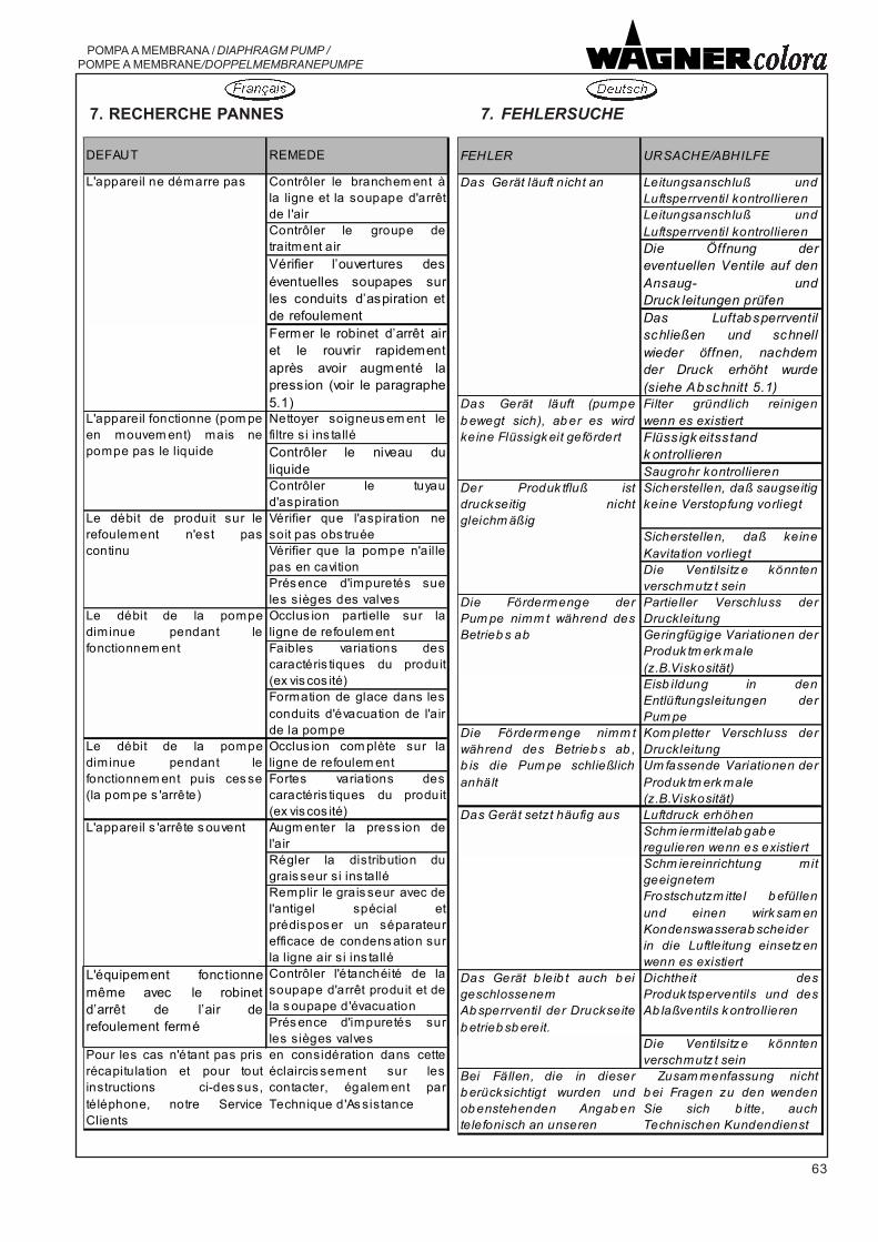
63
POMPA A MEMBRANA / DIAPHRAGM PUMP / POMPE A MEMBRANE/DOPPELMEMBRANEPUMPE
7. RECHERCHE PANNES 7. FEHLERSUCHE
DEFAUT REMEDE
L'appareil ne démarre pas Contrôler le branchem ent àla ligne et la soupape d'arrêtde l'air Contrôler le groupe detraitment airVérifier l�ouvertures deséventuelles soupapes surles conduits d�aspiration etde refoulementFermer le robinet d�arrêt airet le rouvrir rapidementaprès avoir augmenté lapress ion (voir le paragraphe5.1)Nettoyer soigneus em ent lefiltre si ins talléContrôler le niveau duliquideContrôler le tuyaud'aspirationVérifier que l'aspiration nesoit pas obs truéeVérifier que la pompe n'aillepas en cavitionPrés ence d'impuretés sueles sièges des valvesOcclus ion partielle sur laligne de refoulem ent Faibles variations descaractéris tiques du produit(ex vis cos ité)Formation de glace dans lesconduits d'évacuation de l'airde la pompeOcclus ion com plète sur laligne de refoulem ent Fortes variations descaractéris tiques du produit(ex vis cos ité)Augm enter la press ion del'airRégler la distribution dugrais seur si ins talléRemplir le grais seur avec del'antigel spécial etprédispos er un séparateurefficace de condens ation surla ligne air si ins talléContrôler l'étanchéité de lasoupape d'arrêt produit et dela s oupape d'évacuationPrés ence d'impuretés surles sièges valves
Pour les cas n'étant pas prisrécapitulation et pour toutinstructions ci-des sus,téléphone, notre ServiceClients
en considération dans cetteéclaircis sement sur lescontacter, égalem ent parTechnique d'As sistance
L'équipement fonctionnemême avec le robinetd�arrêt de l�air derefoulement fermé
L'appareil fonctionne (pom pe en mouvem ent) mais nepompe pas le liquide
Le débit de produit sur lerefoulement n'est pascontinu
Le débit de la pompediminue pendant lefonctionnem ent
L'appareil s 'arrête s ouvent
Le débit de la pompediminue pendant lefonctionnem ent puis ces se(la pom pe s 'arrête)
FEHLER URSACHE/ABHILFE
Das Gerät läuft nicht an Leitungsanschluß undLuftsperrventil kontrollierenLeitungsanschluß undLuftsperrventil kontrollierenDie Öffnung dereventuellen Ventile auf denAnsaug- undDruck leitungen prüfenDas Luftabsperrventilschließen und schnellwieder öffnen, nachdemder Druck erhöht wurde(siehe Abschnitt 5.1)Filter gründlich reinigenwenn es existiertFlüss igk eitss tand k ontrollierenSaugrohr kontrollieren
Der Produk tfluß istdruckseitig nichtgleichm äßig
Sicherstellen, daß saugseitigkeine Verstopfung vorliegt
Sicherstellen, daß keineKavitation vorliegtDie Ventilsitz e könntenverschmutz t seinPartieller Verschluss derDruckleitung Geringfügige Variationen der Produk tm erk male (z.B.Viskosität)Eisb ildung in denEntlüftungsleitungen derPum peKom pletter Verschluss derDruckleitungUm fassende Variationen derProduk tm erk male (z.B.Viskosität)Luftdruck erhöhenSchm iermittelab gab e regulieren wenn es existiertSchm iereinrichtung mitgeeignetem Frostschutzm ittel b efüllenund einen wirk sam enKondenswasserab scheider in die Luftleitung einsetz enwenn es existiert
Das Gerät b leib t auch b eigeschlossenem Ab sperrventil der Druckseiteb etrieb sb ereit.
Dichtheit desProduk tsperventils und desAb laßventils k ontrollieren
Die Ventilsitz e könntenverschmutz t sein
Bei Fällen, die in dieserb erücksichtigt wurden undob enstehenden Angab entelefonisch an unseren
Zusam menfassung nichtb ei Fragen zu den wendenSie sich b itte, auchTechnischen Kundendienst
Das Gerät setzt häufig aus
Die Fördermenge derPum pe nimm t während desBetrieb s ab
Das Gerät läuft (pumpeb ewegt sich), ab er es wirdkeine Flüssigk eit gefördert
Die Fördermenge nimm twährend des Betrieb s ab ,b is die Pum pe schließlichanhält

64
POMPA A MEMBRANA / DIAPHRAGM PUMP /POMPE A MEMBRANE/DOPPELMEMBRANEPUMPE
8. CATALOGUE PIECES DERECHANGE
8. CATALOGO PARTI DIRICAMBIO
8. SPARE PARTSCATALOGUE
In order to precisely identify the partdesired, the applicant must informWAGNER Colora the code number,position reference and description ofthe part in question given in the sectiondrawing enclosed with this manual,together with the data relating to thepump model, code and serial number.
Afin de localiser le détail souhaité, ledemandeur doit communiquer àWAGNER Colora le numéro de code,la référence de position ainsi que ladescription du détail en objet, indiquéssur le dessin joint à ce Manuel, toutcomme les données relatives aumodèle de la pompe, code etmatricule.
Al fine di individuare esattamente ilparticolare desiderato il richiedentedeve comunicare, alla WAGNERColora, il numero di codice, ilriferimento di posizione e ladescrizione del particolare in oggetto,riportati nel disegno in sezioneallegato a questo manuale,unitamente ai dati relativi al modellodi pompa, codice e matricola.

65
POMPA A MEMBRANA / DIAPHRAGM PUMP / POMPE A MEMBRANE/DOPPELMEMBRANEPUMPE
8. ERSATZTEILE KATALOG
Um das gewünschte Einzelteil exaktermitteln zu können, bittet dieWAGNER Colora die Artikelnummer,die Positionsangabe sowie dieBeschreibung des entsprechendenTeils auf der Schnittzeichnung dieserBetriebsanleitung sowie dasentsprechende Pumpenmodell, dieCodenummer und die Seriennummeranzugeben.
p/n: U560.ATSS1 s/n: 06M24130/001

66
POMPA A MEMBRANA / DIAPHRAGM PUMP /POMPE A MEMBRANE/DOPPELMEMBRANEPUMPE
POMPA ZIP182 METALLICA STANDARD / PUMP ZIP182 METALLIC STANDARDPOMPE ZIP182 MÉTALLIQUE STANDARD / PUMPE ZIP182 METALL STANDARD
27.02.08 coloratecni ®

67
POMPA A MEMBRANA / DIAPHRAGM PUMP /POMPE A MEMBRANE/DOPPELMEMBRANEPUMPE
POMPA ZIP182 METALLICA / PUMP ZIP182 METALLIC POMPE ZIP182 MÉTALLIQUE / PUMPE ZIP182 METALL
U560.ATSS1 (3829431) - U560.ATST1 (3833182)
POS. DESCRIZIONE/DESCRIPTION/DESCRIPTION/BESCHREIBUNG Q./QTY . CODICE/CODE CODICE/CODE(Wagner ref.No.)
1 Disco membrana est./Outer diaphragm disk / Disque membraneext./ext. Membranscheibe
2 F9005.01 (3827682)
2 Rondella di tenuta/Sealing washer /Rondelle d'etancheite/Dichtungsring
2 B0315.03 (3832007)
3 Collettore mandata/Delivery manifold /Collecteur derefoul./Druckseitiger Verteiler
1 F1001.01 (3827956)
4 Collettore asp./Suction manifold /Collecteur d'asp./Saugseitiger Verteiler
1 F1002.01 (3827955)
5 Coperchio membrana/Diaphragm cover /Couvercle membrane/Membrandeckel
2 F994.01 (3826610)
6 Membrana prodotto/Product diaphragm / Membrane produit/Membran Produkt
2 G924.05 (3827863)
7 Membrana di sostegno/Support diaphragm /Membrane desoutien/Stützmembran
2 G924.06 (3827864)
8 Vite autofil./Self-tapping screw /Vis autotaraudeuse/Selbstdrehende Gewindeschrauben
1 K1012.62 (3824741)
9 Vite/Screw /Vis/Schrauben 16 K1015.62 (3818332)10 Rivetto/Rivet /Rivet/Niet 6 K1041.62 (3823170)11 Staffetta antirotazione/Antirotation racket /Bride
antirotation/Antirotationsbügel1 E0043.62A (3828844)
12 Vite/Screw /Vis/Schrauben 8 K1003.62 (3806997)13 Vite/Screw /Vis/Schrauben 4 K193.62 (3828021)14 Dado autobloccante/Self-tightening nut /Ecrou auto-
bloquant/Selbstsperrende Mutter28 K312.62 (3807204)
15 Rosetta/Washer /Rondelle/Unterlagsscheibe 28 K509.62 (3807272)16 O-ring/O-ring/ O-ring/O-Ring 2 L219.05 (3827895)17 Motore/Motor /Moteur/Motor 1 T6124.00 (3827960)18 Gruppo valvola fluido/Fluid valve unit /Groupe soupape
fluide/Flüssigkeits-VentileinheitU560.ATSS1 (3829431) 4 T6125.00 (3827961)U560.ATST1 (3833182) 4 T6125.00C (3833181)
19 Capocorda/Lug /Borne/Kabelschuh 1 Y622.00A (3816412)20 Targhetta laterale/Side plate /Plaquette latérale/Laterales
Typenschild 2 Z595.00 (3828030)
21 Targhetta coperchio/Cover plate /Plaquette couvercle/Deckeltypenschild
1 Z596.00X (3829338)
22 Vite/Screw /Vis/Schrauben 2 K1060.03 (3828007)
12.01.07 coloratecni ®
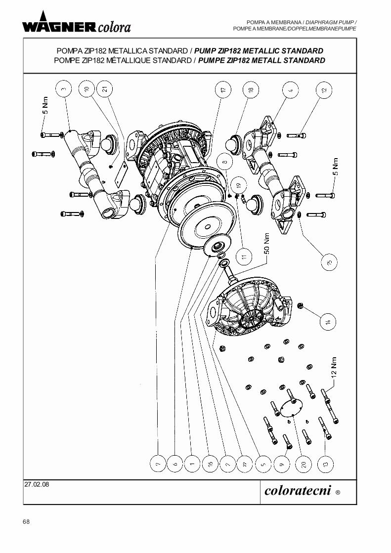
68
POMPA A MEMBRANA / DIAPHRAGM PUMP /POMPE A MEMBRANE/DOPPELMEMBRANEPUMPE
POMPA ZIP182 METALLICA STANDARD / PUMP ZIP182 METALLIC STANDARDPOMPE ZIP182 MÉTALLIQUE STANDARD / PUMPE ZIP182 METALL STANDARD
27.02.08 coloratecni ®

69
POMPA A MEMBRANA / DIAPHRAGM PUMP /POMPE A MEMBRANE/DOPPELMEMBRANEPUMPE
POMPA ZIP182 INOX / ZIP182 STAINLESS STEEL PUMP POMPE ZIP182 INOX / PUMPE ZIP182 EDELSTAHL
U560.STSS1 (3829432) - U560.STST1 (3834855)
POS. DESCRIZIONE/DESCRIPTION /DESCRIPTION/BESCHREIBUNG Q./QTY . CODICE/CODE CODICE/CODE(Wagner ref.No.)
1 Disco membrana est./Outer diaphragm disk / Disque membraneext./ext. Membranscheibe
2 B0235.03A (3835585)
2 Rondella di tenuta/Sealing washer /Rondelle d'etancheite/Dichtungsring
2 B0315.03 (3832007)
3 Collettore mandata/Delivery manifold /Collecteur derefoul./Druckseitiger Verteiler
1 F1003.03 (3828078)
4 Collettore asp./Suction manifold /Collecteur d'asp./Saugseitiger Verteiler
1 F1004.03 (3828082)
5 Coperchio membrana/Diaphragm cover /Couvercle membrane/Membrandeckel
2 F1005.03 (3828125)
6 Membrana prodotto/Product diaphragm / Membrane produit/Membran Produkt
2 G924.05 (3827863)
7 Membrana di sostegno/Support diaphragm /Membrane desoutien/Stützmembran
2 G924.06 (3827864)
8 Vite autofil./Self-tapping screw /Vis autotaraudeuse/Selbstdrehende Gewindeschrauben
1 K1012.62 (3824741)
9 Vite/Screw /Vis/Schrauben 16 K1015.62 (3818332)10 Rivetto/Rivet /Rivet/Niet 6 K1041.62 (3823170)11 Staffetta antirotazione/Antirotation racket /Bride
antirotation/Antirotationsbügel1 E0043.62A (3828844)
12 Vite/Screw /Vis/Schrauben 8 K146.62 (3807096)13 Vite/Screw /Vis/Schrauben 4 K193.62 (3828021)14 Dado autobloccante/Self-tightening nut /Ecrou auto-
bloquant/Selbstsperrende Mutter28 K312.62 (3807204)
15 Rosetta/Washer /Rondelle/Unterlagsscheibe 28 K509.62 (3807272)16 O-ring/O-ring/ O-ring/O-Ring 2 L219.05 (3827895)17 Motore/Motor /Moteur/Motor 1 T6124.00 (3827960)18 Gruppo valvola fluido/Fluid valve unit /Groupe soupape
fluide/Flüssigkeits-VentileinheitU560.STSS1 (3829432) 4 T6125.00 (3827961)U560.STST1 (3834855) 4 T6125.00C (3833181)
19 Capocorda/Lug /Borne/Kabelschuh 1 Y622.00A (3816412)20 Targhetta laterale/Side plate /Plaquette latérale/Laterales
Typenschild 2 Z595.00 (3828030)
21 Targhetta coperchio/Cover plate /Plaquette couvercle/Deckeltypenschild
1 Z596.00X (3829338)
22 Vite/Screw /Vis/Schrauben 2 K1060.03 (3828007)
27.02.08 coloratecni ®

70
POMPA A MEMBRANA / DIAPHRAGM PUMP /POMPE A MEMBRANE/DOPPELMEMBRANEPUMPE
MOTORE ZIP182/MOTOR /MOTEUR/MOTORT6124.00 (3827960)
06.06.06
coloratecni ®

71
POMPA A MEMBRANA / DIAPHRAGM PUMP /POMPE A MEMBRANE/DOPPELMEMBRANEPUMPE
MOTORE ZIP182/MOTOR ZIP182 /MOTEUR ZIP182/MOTOR ZIP182
POS. DESCRIZIONE/DESCRIPTION /DESCRIPTION/BESCHREIBUNG Q./QTY . CODICE/CODE CODICE/CODE(Wagner ref.No.)
1 Albero/Shaft /Arbre/Welle 1 B0223.03 (3827872)2 Bussola guida stelo/Bushing guide rod /Douille guide
tige/Schaftführungsbuchse 2 B0224.07 (3827873)3 Bussola tastatore/Feeler pin bushing /Douille capteur/Tastbuchse 2 B0227.07 (3827874)4 Tastatore/Feeler pin /Capteur/Fühler 2 B0260.03 (3828931)5 Disco di rinforzo/Strengthening disk /Disque de
renforcement/Verstärkungsscheibe2 B0305.62 (3831765)
6 Blocco motore/Motor block/ Bloc moteur/Motorblock 1 F1006.91 (3830154)7 Coperchio lato pressione/Cover (pressure side) /Couvercle côté
pression/Deckel Druckseite1 F9003.01 (3827680)
8 Disco membrana interno/Inner diaphragm disk/ Disque membrane int./int. Membranscheibe
2 F9004.01 (3827681)
9 Flangia aria/Air flange /Bride air/Luftflansch 2 F9006.01 (3827689)10 Guarnizione coperchio pressione/Pressure cover gasket /Garniture
couvercle pression/Druckdeckeldichtung 1 G7024.06 (3827712)
11 Guarnizione flangia/Flange gasket /Garniture bride/Flanschdichtung
2 G7025.06 (3827714)
12 Guarnizione centro flangia/Center flange gasket /Garniture centrebride/Dichtung für Flanschzentrum
2 G7026.06 (3827718)
13 Vite/Screw /Vis/Schrauben 28 K1058.62 (3827899)14 Vite/Screw /Vis/Schrauben 4 K1059.62 (3828006)15 O-ring/O-ring/ O-ring/O-Ring 4 L221.06 (3827909)16 Guarnizione a labbro/Lip gasket/Garniture à lèvres/Randdichtung 2 L474.06 (3827907)17 Guarnizione a labbro/Lip gasket/Garniture à lèvres/Randdichtung 2 L475.06 (3827908)18 Valvola inversione/Reversing valve/ Soupape
d'inversion/Umkehrventil1 P4018.00 (3827838)
19 Valvola di sicurezza/Safety valve /Soupape desûreté/Sicherheitsventil
1 T6121.00 (3827888)
20 Rondella di contatto/Contact washer /Rondelle decontact/Kontaktrondelle
3 K564.72 (3829322)
21 Rondella/Washer /Rondelle/Scheibe 4 G7029.07 (3831772)
06.06.06 coloratecni ®
T6124.00 (3827960)

72
POMPA A MEMBRANA / DIAPHRAGM PUMP /POMPE A MEMBRANE/DOPPELMEMBRANEPUMPE
SERVICE SET
Set valvola inversione / Reversing valve set Q.tà Codice Wagner Set soupape d'inversion / Umkehrventilsatz Z IP182 Q.ty Code ref.no.cod. P4018.00 (3827838) CodeComposto da/Consist of /Comprenant/Bestehend aus:Valvola/Valve/ Soupape/VentilGuarnizione valvola inversione/Reversing valve gasket /Garniture soupaped�inversion/Umsteuerventildichtung 1 G927.06 (3827707)Guarnizione coperchio pressione/Pressure cover gasket /Garniture couverclepression/Druckdeckeldichtung 1 G7024.06 (3827712)
Service set fluido - membrane PTFE - valvole inox Q.tà Codice Wagner Fluid service set - PTFE diaphragms - stainless steel valves Q.ty Code ref.no.Service set fluide - membranes PTFE - soupapes inox Q.té CodeFlüssigkeits-Servicesatz - Membranen PTFE - Ventile Edelstahl Men. Codecod. T9087.00 (3832149)Composto da/Consist of /Comprenant/Bestehend aus:Membrana prodotto/Product diaphragm / Membrane produit/Membran Produkt 2 G924.05 (3827863)Membrana di sostegno/Support diaphragm /Membrane desoutien/Stützmembran 2 G924.06 (3827864)Set o-ring prodotto/Product o-ring set /Set o-ring produit/Produkt o-ring-satz 1 T9088.00 (3832150)Sede inox/Stainless steel seat /Siége inox/Sitz Edelstahl 4 B0231.03A (3827894)Sfera inox/Stainless steel ball /Bille inox/Kugel Edelstahl 4 K836.03 (3827957) Guarnizione a labbro tastatore/Feeler pin lip gasket /Garniture à lèvrescapteur/Randdichtung Fühler 2 L475.06 (3827908)Guarnizione a labbro/Shaft lip gasket /Garniture à lèvres arbre/Randdichtung Welle 2 L474.06 (3827907)Bussola guida stelo/Bushing guide rod /Douille guidetige/Schaftführungsbuchse 2 B0224.07 (3827873)O-ring NBR/O-ring/ O-ring/O-Ring 4 L221.06 (3827909)Bussola tastatore/Feeler pin bushing /Douille capteur/Tastbuchse 2 B0227.07 (3827874)Guarnizione centro flangia/Center flange gasket /Garniture centrebride/Dichtung für Flanschzentrum 2 G7026.06 (3827718)Guarnizione flangia/Flange gasket /Garniture bride/Flanschdichtung 2 G7025.06 (3827714)O-ring PTFE/O-ring/ O-ring/O-Ring 2 L219.05 (3827895)Vite TE M16x50/Screw /Vis/Schrauben 2 K1060.03 (3828007)Rondella di tenuta/Sealing washer /Rondelle d'etancheite/Dichtungsring 2 B0315.03 (3832007)
Set o-ring prodotto / Product o-ring set Q.tà Codice Wagner Set o-ring produit / Produkt o-ring-satz Q.ty Code ref.no.cod. T9088.00 (3832150) CodeComposto da/Consist of /Comprenant/Bestehend aus:O-ring (PTFE)/O-ring /O-ring/O-ring 4 L222.05 (3827958)

73
POMPA A MEMBRANA / DIAPHRAGM PUMP / POMPE A MEMBRANE/DOPPELMEMBRANEPUMPE
PAGINA LASCIATA INTENZIONALMENTE VUOTAPAGE LEFT INTENTIONALLY BLANKPAGE LAISSEE EN BLANCLEERSEITE

74
POMPA A MEMBRANA / DIAPHRAGM PUMP /POMPE A MEMBRANE/DOPPELMEMBRANEPUMPE
TIMBRO DEL CONCESSIONARIO
DEALER'S STAMP
TAMPON DU CONCESSIONNAIRE
STEMPEL IHRES HÄNDLERS