polarization reconfigurable antennas for space … fileiii specially dedicated to my beloved parent,...
TRANSCRIPT

i
POLARIZATION RECONFIGURABLE ANTENNAS FOR
SPACE LIMITED MULTIPLE INPUT MULTIPLE OUTPUT SYSTEM
MOHAMED NASRUN BIN OSMAN
UNIVERSITI TEKNOLOGI MALAYSIA
5
POLARIZATION RECONFIGURABLE ANTENNAS FOR SPACE LIMITED
MULTIPLE INPUT MULTIPLE OUTPUT SYSTEM
MOHAMED NASRUN OSMAN
A thesis submitted in fulfilment of
requirements for the award of the degree of
Doctor of Philosophy (Electrical Engineering)
Faculty of Electrical Engineering
Universiti Teknologi Malaysia
JUNE 2016

iii
Specially dedicated to my beloved parent, Che Ah bt Saleh and Baharum b Hanapiah
my late father, Osman b Bakar, my wife and daughter, Dyia Syaleyana bt Md Shukri
and Dhiyaa Naqeesya, my parent-in-laws, and my siblings with love and care.

iv
ACKNOWLEDGEMENT
First of all, praise and thank to ALLAH for His continuous blessings, strength
and guidance given to me in completing this study.
I was contact with many people throughout this period of study. In particular,
I would like to express my heartfelt appreciations to my supervisor, Prof. Dr.
Mohamad Kamal A. Rahim and my co-supervisors, Dr. Mohd Fairus Mohd Yusoff
and Dr. Mohamad Rijal Hamid for their encouragements and advises. Not to forget
Dr Peter Gardner and Dr Muzammil Jusoh. Their valuable guidance, comments and
constant endeavour massively help me to perform research on the right path and
organized way, to ensure the research conducted smoothly.
I am also indebted to Universiti Malaysia Perlis and Ministry of Education
for funding my study. I also would like extend my great gratitude to all P18
members; UTM‟s and UniMAP‟s lecturers and colleagues, for the sharing of
knowledge, ideas, and tips which absolutely helping me a lot.
My greatest thanks to my family; especially to my parent, parent-in-law and
siblings whose has given me unlimited encouragement, support and caring. My
deepest appreciation to my wife, Dyia Syaleyana Md Shukri for her enormous
understanding, moral support and endless love that are the key of my strength to
complete the study.
Finally, I would like to thanks to all person where their names are not
mentioned here but have been a great helps and contributions during this journey of
study whether it‟s directly or indirectly. Thank you for all of your kindness and
generosity.
v
ABSTRACT
Wireless communication undergoes rapid changes in recent years. More and
more people are using modern communication services, thus increasing the need for
higher capacity in transmission. One of the methods that is able to meet the demands is
the use of multiple antennas at both link ends known as Multiple Input Multiple Output
(MIMO) system. However, for the space limited MIMO system, it is relatively difficult
to accomplish good performance by using conventional antennas. Therefore, to further
improve the performance offered by MIMO, Polarization Reconfigurable Antennas
(PRAs) can be adopted. The diversity in polarization can be exploited to increase
channel capacity. Moreover, the use of PRAs can also provide savings in terms of space
and cost by arranging orthogonal polarized together instead of two physically space
separation antennas. Here, single and dual port PRAs are proposed. Two techniques are
deployed to achieve the PRAs are slits perturbation (switches on the radiating patch) and
alteration of the feeding network (switches on the ground plane). Switching mechanism
(ideal and PIN diode) is introduced to reconfigure the polarization between left-hand
circular polarizations, right-hand circular polarizations, or linear polarization, operating
at wireless local area network frequency band (2.4 – 2.5 GHz). Furthermore, by
exploiting the odd and even mode of the coplanar waveguide structure, dual ports PRAs
are realized with the ability to produce orthogonal linear polarization (LP) and circular
polarization (CP) modes simultaneously. Good measured port polarization isolations
(S21) of -16.3 dB and -19 dB are obtained at the frequency of 2.45 GHz for configuration
A1 (orthogonal LP) and A2 (orthogonal CP), respectively. The proposed PRAs are
tested in 2 x 2 MIMO indoor environments to validate their performances by using
scalar power correlation method when applied as receiver in both line-of-sight (LOS)
and non-line-of-sight (NLOS) scenarios. Channel capacity improvement has been
achieved for spatial diversity (92.9% for LOS and 185.9% for NLOS) and polarization
diversity (40.7% for LOS and 57.9% for NLOS). The proposed antenna is highly
potential to be adopted to enhance the performance of the MIMO system, especially in
dealing with multipath environment and space limited applications.
vi
ABSTRAK
Dewasa ini, komunikasi tanpa wayar telah berubah dengan pesatnya. Semakin
ramai orang telah menggunakan perkhidmatan komunikasi moden, sekaligus
meningkatkan permintaan untuk kapasiti yang lebih tinggi. Salah satu daripada kaedah
untuk memenuhi permintaan ini adalah dengan menggunakan beberapa antena di kedua-
dua bahagian sistem perhubungan, iaitu menggunakan sistem Berbilang Masukan
Berbilang Keluaran (MIMO). Walau bagaimanapun, untuk mencapai prestasi yang baik
di dalam sistem MIMO ruang terhad dengan menggunakan antena konvensional secara
relatifnya agak sukar. Maka, untuk meningkatkan prestasi MIMO, antena-antena dengan
Pengutuban Boleh Ubah (PRAs) telah digunakan. Pengutuban kepelbagaian boleh
dimanipulasikan untuk meningkatkan kapasiti saluran. Tambahan lagi, penggunaan
PRAs juga boleh menjimatkan ruang dan kos, dengan meletakkan antena berpengutuban
serenjang bersama berbanding dua antena berjarak dengan ruang. Di dalam kajian ini,
satu dan dua pangkalan PRAs dicadangkan. Dua teknik telah diguna untuk
menghasilkan PRAs, iaitu pengusikan belahan (suis di tampalan terpancar) dan
pengubahan rangkaian suapan (suis di satah pembumian). Mekanisme suis (ideal dan
PIN diod) telah diperkenalkan untuk mengubah pengutuban antena kepada pengutuban
bulatan tangan kiri, pengutuban bulatan tangan kanan atau pengutuban lelurus, yang
beroperasi pada jalur frekuensi rangkaian kawasan setempat tanpa wayar
(2.4 – 2.5 GHz). Tambahan pula, dua pangkalan PRAs dengan kebolehan menghasilkan
mod pengutuban serenjang lelurus (LP) dan bulatan (CP) dengan serentak telah
dibangunkan dengan menggunakan ciri mod genap dan ganjil struktur sesatah pandu
gelombang. Isolasi (S21) pengukuran pengutuban pangkalan yang baik telah dicapai pada
frekuensi 2.45 GHz, iaitu -16.3 dB untuk konfigurasi A1 (LP berserenjang) dan -19 dB
untuk konfigurasi A2 (CP berserenjang). PRAs yang dicadangkan ini telah diuji di
dalam senario garis penglihatan (LOS) dan bukan garis penglihatan (NLOS) untuk 2 x 2
persekitaran tertutup MIMO bagi mengesahkan prestasinya menggunakan kaedah
hubung kait kuasa skalar apabila diaplikasikan sebagai antena penerima. Peningkatan
kapasiti saluran telah dicapai untuk diversiti keruangan (92.9% untuk LOS dan 185.9%
untuk NLOS) dan diversiti pengutuban (40.7% untuk LOS dan 57.9% untuk NLOS).
Antena yang dicadangkan ini amatlah berpotensi untuk diguna bagi meningkatkan
prestasi sistem MIMO, terutama dalam menangani persekitaran pelbagai arah dan
aplikasi ruang terhad.

vii
TABLE OF CONTENTS
CHAPTER TITLE PAGE
DECLARATION ii
DEDICATION iii
ACKNOWLEDGEMENT iv
ABSTRACT v
ASBTRAK vi
TABLE OF CONTENTS vii
LIST OF TABLES xi
LIST OF FIGURES xiii
LIST OF ABBREVIATIONS xx
LIST OF SYMBOLS xxii
LIST OF APPENDICES xxiii
1 INTRODUCTION 1
1.1 Introduction and Background 1
1.2 Problem Statements
4
1.3 Research Motivations 5
1.4 Research Objectives 6
1.5 Scope of the Research 7
1.6 Outline of the Thesis 8
viii
2 LITERATURE REVIEW 10
2.1 Introduction 11
2.2 Polarization 12
2.3 Reconfigurable Antenna 16
2.4 Polarization Reconfigurable Antenna 19
2.5 Coplanar Waveguide (CPW) 33
2.6 Biasing Technique and RF Component 39
2.7 Multiple-Input-Multiple-Output (MIMO) 45
2.8 Chapter Summary 60
3 RESEARCH METHODOLOGY 62
3.1 Introduction 62
3.2 Methodology 65
3.3 Design and Simulation (Stage 1) 66
3.3.1 Design Specification 66
3.3.2 Microstrip Circular Patch Antenna 67
3.3.3 Ideal and PIN Diode 69
3.3.4 Simulation Process in CST Software 72
3.4 Fabrication and Validation (Stage 2) 76
3.5 Diversity Performances and MIMO
Capacity Measurement (Stage 3) 81
3.6 Chapter Summary 84
4 SINGLE PORT POLARIZATION
RECONFIGURABLE ANTENNA 86
4.1 Introduction 87
4.2 Design A: Polarization Reconfigurable Antenna
Using Slit‟s Perturbation Technique 87

ix
4.2.1 Antenna Design, Approach and
Configurations 88
4.2.2 Parametric Study 92
4.2.3 Simulation, Measurement and Validation
(Ideal Diode) 97
4.2.4 Simulation, Measurement and Validation
(PIN Diode) 99
4.3 Slit‟s Perturbation Technique: Polarization
Reconfigurable Antenna with Fixed Operating
Frequency 104
4.3.1 Stage 1: Proof of the Concept (Ideal Diode) 105
4.3.2 Stage 2: Realization of Active Switching
(PIN Diode) 111
4.3.3 Bandwidth Improvement 118
4.4 Design B: Modification of Feeding Network
Technique
Technique 125
4.4.1 Antenna Design, Approach and
Configurations 125
4.4.2 Parametric Study 129
4.4.3 Simulation Results 132
4.5 Comparison of the Techniques 136
4.6 Chapter Summary 140
5 DUAL-PORT POLARIZATION
ccccddfdfdRECONRECONFIGURABLE
RECONFIGURABLE ANTENNA 141
5.1 Introduction 141
5.2 Antenna Design, Approach and Configurations 143
5.3 Measurement and Validation 147

x
5.4 Analysis and Verification of Discrepancies
152
5.4.1 Effect of Existence of Glue Layer 152
5.4.2 Effect of Proper Position to Mount RF PIN
Diode 157
5.4.3 Selection of Type of RF Switches and DC
Bias Cable 159
5.5 CPW Slotline with Two Phase Delays 159
5.6 Chapter Summary 164
6 EXPERIMENTAL ANALYSIS OF POLARIZATION
RECONFIGURABLE FOR MIMO SYSTEMS 164
6.1 Introduction 164
6.2 Diversity Performances Evaluation 166
6.3 Experimental Setup and Scenario 167
6.4 Results and Discussions 172
6.5 Chapter Summary 177
7 CONCLUSION AND FUTURE WORK 178
7.1 Conclusion 178
7.2 Key Contribution 180
7.3 Future Work 181
REFERENCES 184
Appendices A-F 196-223
xi
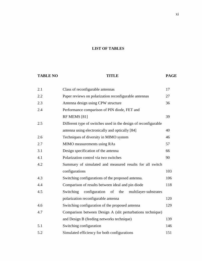
LIST OF TABLES
TABLE NO TITLE PAGE
2.1 Class of reconfigurable antennas 17
2.2 Paper reviews on polarization reconfigurable antennas 27
2.3 Antenna design using CPW structure 36
2.4 Performance comparison of PIN diode, FET and
RF MEMS [81] 39
2.5 Different type of switches used in the design of reconfigurable
antenna using electronically and optically [84] 40
2.6 Techniques of diversity in MIMO system 46
2.7 MIMO measurements using RAs 57
3.1 Design specification of the antenna 66
4.1 Polarization control via two switches 90
4.2 Summary of simulated and measured results for all switch
configurations
103
4.3 Switching configurations of the proposed antenna. 106
4.4 Comparison of results between ideal and pin diode 118
4.5 Switching configuration of the multilayer-substrates
polarization reconfigurable antenna
120
4.6 Switching configuration of the proposed antenna 129
4.7 Comparison between Design A (slit perturbations technique)
and Design B (feeding networks technique)
139
5.1 Switching configuration 146
5.2 Simulated efficiency for both configurations 151
xii
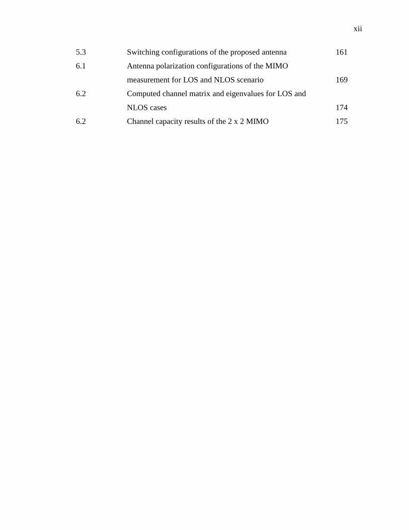
5.3 Switching configurations of the proposed antenna 161
6.1 Antenna polarization configurations of the MIMO
measurement for LOS and NLOS scenario
169
6.2 Computed channel matrix and eigenvalues for LOS and
NLOS cases
174
6.2 Channel capacity results of the 2 x 2 MIMO 175
xiii
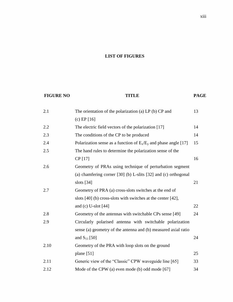
LIST OF FIGURES
FIGURE NO TITLE PAGE
2.1 The orientation of the polarization (a) LP (b) CP and
(c) EP [16]
13
2.2 The electric field vectors of the polarization [17] 14
2.3 The conditions of the CP to be produced 14
2.4 Polarization sense as a function of Ex/Ey and phase angle [17] 15
2.5 The hand rules to determine the polarization sense of the
CP [17]
16
2.6 Geometry of PRAs using technique of perturbation segment
(a) chamfering corner [30] (b) L-slits [32] and (c) orthogonal
slots [34]
21
2.7 Geometry of PRA (a) cross-slots switches at the end of
slots [40] (b) cross-slots with switches at the center [42],
and (c) U-slot [44] 22
2.8 Geometry of the antennas with switchable CPs sense [49] 24
2.9 Circularly polarised antenna with switchable polarization
sense (a) geometry of the antenna and (b) measured axial ratio
and S11 [50]
24
2.10 Geometry of the PRA with loop slots on the ground
plane [51]
25
2.11 Generic view of the “Classic” CPW waveguide line [65] 33
2.12 Mode of the CPW (a) even mode (b) odd mode [67] 34
xiv
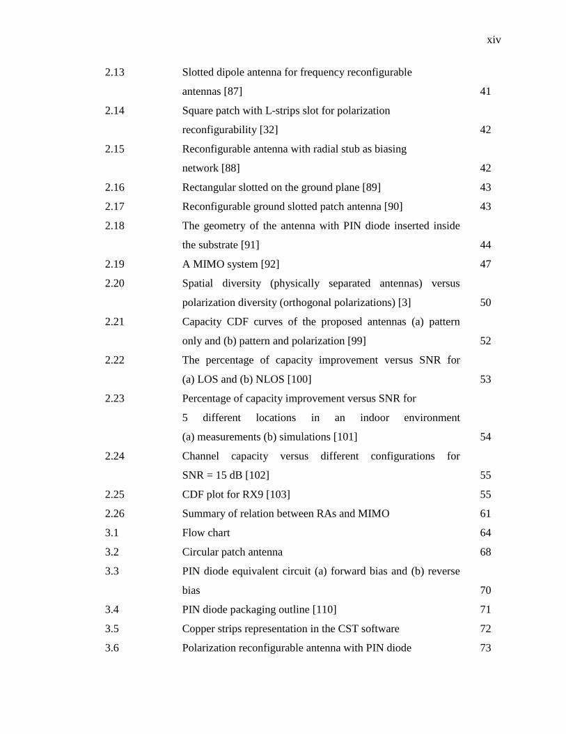
2.13 Slotted dipole antenna for frequency reconfigurable
antennas [87]
41
2.14 Square patch with L-strips slot for polarization
reconfigurability [32]
42
2.15 Reconfigurable antenna with radial stub as biasing
network [88]
42
2.16 Rectangular slotted on the ground plane [89] 43
2.17 Reconfigurable ground slotted patch antenna [90] 43
2.18 The geometry of the antenna with PIN diode inserted inside
the substrate [91]
44
2.19 A MIMO system [92] 47
2.20 Spatial diversity (physically separated antennas) versus
polarization diversity (orthogonal polarizations) [3]
50
2.21 Capacity CDF curves of the proposed antennas (a) pattern
only and (b) pattern and polarization [99]
52
2.22 The percentage of capacity improvement versus SNR for
(a) LOS and (b) NLOS [100]
53
2.23 Percentage of capacity improvement versus SNR for
5 different locations in an indoor environment
(a) measurements (b) simulations [101]
54
2.24 Channel capacity versus different configurations for
SNR = 15 dB [102]
55
2.25 CDF plot for RX9 [103] 55
2.26 Summary of relation between RAs and MIMO 61
3.1 Flow chart 64
3.2 Circular patch antenna 68
3.3 PIN diode equivalent circuit (a) forward bias and (b) reverse
bias
70
3.4 PIN diode packaging outline [110] 71
3.5 Copper strips representation in the CST software 72
3.6 Polarization reconfigurable antenna with PIN diode 73
xv
3.7 Discrete port position in the simulation 74
3.8 Circuit schematic simulation in CST 74
3.9 Antenna with biasing network included in the simulation 75
3.10 Antenna fabrication flowchart 76
3.11 Switching board 77
3.12 Rohde & Schwartz ZVL network analyser 79
3.13 Layout of the radiation pattern, gain and axial ratio
measurement
79
3.14 Radiation pattern measurement setup at UniMAP 80
3.15 Radiation pattern measurement at UoB 80
3.16 The process of 2 x 2 MIMO channel capacity measurement 82
3.17 The summary of the process determining channel capacity 84
4.1 Geometry of the proposed antenna for ideal diode-
Front view (left) and Side view (right).
(Dimensions in mm: L= 55, W= 55, Ls= 6.5, Lp= 15.3, Ws= 1,
W2= 1, r= 18.1, d= 5.5)
88
4.2 Geometry of the proposed antenna for RF PIN diode-
Front view (left) and Side view (right). (Dimensions in mm:
L= 55, W= 55, Ls= 7, Lp= 15.5, Ws= 1, W2= 1, r= 17.8,
d= 5.25)
89
4.3 Fabricated proposed antenna for (a) ideal diode and (b) PIN
diode
91
4.4 Effect of slit length, Ls (mm) towards the (a) S11 and (b) AR 93
4.5 Study on the effect towards (a) S11, and (b) AR when Ls (mm)
is varied from 5.5mm to 7.5mm.
94
4.6 Effect of the feeding point, d (mm) towards the S11 (dB) result 95
4.7 Effect of the change of switch position, Lp (mm) towards
(a) S11, and (b) AR.
96
4.8 Simulated and measured reflection coefficient, S11 results for
(a) LPs and (b) CPs.
97
4.9 Simulated and measured AR (dB) for CPs operation 98
xvi
4.10 Simulated and measured radiation pattern (x-z plane and y-z
plane) for (a) C1-LP at 2.436 GHz and (b) C3-LHCP at
2.478 GHz 99
4.11 Simulated and measured reflection coefficient, S11 results for
C1-LP and C2-LP
100
4.12 Simulated and measured reflection coefficient, S11 results for
C3-LHCP and C4-RHCP
101
4.13 Simulated and measured normalized radiation pattern for all
switches configurations at the resonant frequency for
(a) C1-LP, (b) C2-LP, (c) C3-LHCP, and (d) C4-RHCP
102
4.14 Simulated and measured AR results for C3-LHCP and C4-
RHCP
103
4.15 Simulated reflection coefficient, S11 (dB) 104
4.16 Geometry of the proposed antenna. (a) front view and
(b) side view. (Dimensions in mm: L= 55, W=55, d=5.5,
r=17.9, Ws=1, W2=1, Ls=5, Lp= 15.3)
105
4.17 The physical structure of the proposed antenna used in the
simulation. (a) C1-LHCP. (b) C2-RHCP. (c) C3-LP.
106
4.18 Front view photograph of fabricated antenna prototypes.
(a) C1-LHCP. (b) C2-RHCP. (c) C3-LP.
107
4.19 Comparison of simulated and measured reflection coefficient
of the proposed antenna. (a) C1-LHCP. (b) C2-RHCP.
(c) C3-LP
108
4.20 Simulated and measured axial ratio 109
4.21 Simulated and measured normalized farfield radiation pattern
at frequency of 2.47 GHz. (a) C1-LHCP. (b) C2-RHCP.
(c) C3-LP
110
4.22 Geometry of the proposed antenna with the integration of
biasing mechanism. (a) front view and (b) back view
(Dimensions in mm: L= 55, W= 55, d= 5.5, r= 17.9,
Ws= 1, Wb= 0.3, Ls= 5, Lp= 17, Lb1= 5, Lb2= 4, Lc= 4.
112
xvii
4.23 Photograph of fabricated antenna prototypes. (a) front view
and (b) back view.
113
4.24 Comparison between simulated and measured reflection
coefficient result of the modified structure. (a) Circular
polarization. (b) C3-LP.
115
4.25 Simulated and measured axial ratio of the modified structure. 116
4.26 Measured normalized radiation pattern of the modified
structure. (a) C1-LHCP at 2.47 GHz. (b) C2-RHCP at
2.47 GHz. (c) C3-LP at 2.49 GHz.
117
4.27 Geometry of the multilayer-substrates polarization
reconfigurable antenna. (a) front view. (b) side view.
119
4.28 Simulated reflection coefficient for all switch configurations 121
4.29 Simulated AR for CP mode 121
4.30 Simulated gain for all switch configurations 122
4.31 3D perspective view of radiation pattern for C2-RHCP at
2.55 GHz.
122
4.32 E-field at 2.45 GHz for C2-RHCP at the phase (a) 0º, (b) 90º,
(c) 180º, and (d) 270º.
123
4.33 Comparison of simulated reflection coefficient for
configuration C2-LHCP with multi-layer of substrate
124
4.34 Comparison of simulated AR for configuration C2-LHCP
with multi-layer of substrate
124
4.35 Geometry and the biased voltage polarity of the proposed
antenna. (top) Front view. (bottom) Back view.
(Yellow colour indicates the metallization of the structure and
white colour for substrate)
128
4.36 Effect of the Ld1 (mm) towards the (a) S11 (dB), and (b) AR 131
4.37 Effect of the Lt (mm) towards the S11 (dB) result 131
4.38 Effect of the Wt (mm) towards the S11 (dB) result 132
xviii
4.39 Simulated reflection coefficient of the proposed antenna for
all switch configurations
133
4.40 Simulated ARs over frequency for CP operations 134
4.41 Simulated radiation pattern (x-z plane and y-z plane) at 2.45
GHz for configuration (a) A1-LP. (b) A2-RHCP. and (c) A3-
LHCP
135
4.42 Simulated gain over frequency for all switch configurations 136
4.43 Simulated reflection coefficient and AR between both design
(a) CP and (b) LP
137
4.44 Comparison of simulated AR between both designs 138
5.1 Geometry and voltage polarity of the proposed antenna. (top)
Front view. (middle) Side view. (bottom) Back view. (Yellow
colour indicates the metallization of the structure, and white
colour for substrate)
144
5.2 Electric field distribution of the CPW. (a) even mode - Port 1
and (b) odd mode - Port 2
145
5.3 Photograph of the fabricated antenna (a) front view and
(b) back view
146
5.4 Measured and simulated S-parameters versus frequency of the
proposed antenna for (a) A1 and (b) A2
148
5.5 Measured and simulated AR versus frequency of the proposed
antenna for configuration A2
149
5.6 Measured normalized radiation pattern of the proposed
antenna. (a) A1 and (b) A2
150
5.7 Simulated current distribution for configuration A1. (a) port 1
and (b) port 2
151
5.8 Simulated current distribution for configuration A2. (a) port 1
and (b) port 2
151
5.9 Antenna with glue layer thickness, ta 153
5.10 The simulated S-parameters for A1 when varying ta. (a) S11
(b) S21 and (c) S22
154
xix
5.11 The simulated S-parameters for A2 when varying ta. (a) S11
(b) S21 and (c) S22
156
5.12 The simulated AR for A2 when ta is varied from 0 mm to 0.5
mm. (a) Port 1 and (b) Port 2
157
5.13 The simulated S-parameters for (a) A1 and (b) A2 when
changing the position of negative polarity of PIN diode
158
5.14 Geometry of the proposed antenna (top) front view and
(bottom) back view. The dimension of the design antennas are
as follows (all unit in millimeters): L = 90, W = 90, r = 18.25,
Lf = 40, Wf = 2, g = 10, Wc = 2.8, La = 40.75, Lb = 24.5,
Lc = 11, Ld = 11.65, Ld1 = 13, Ld2 = 14.75, Lt = 6, Wslot = 0.5,
Wt = 4.4. (Yellow colour indicates the copper area of the
structure, and white colour for the substrate)
160
5.15 The simulated S-parameters versus frequency of the proposed
antenna for configuration (a) A1 (b) A2 (c) A3 and (d) A4
162
5.16 The simulated axial ratio over frequency of the proposed
antenna for CP operations
163
6.1 Simulated and measured ECC of the dual port PRAs 166
6.2 Simulated and measured DG of the dual port PRAs 166
6.3 Laboratory floor layout 168
6.4 Photograph of the microwave laboratory 168
6.5 Channel capacity measurement setup 171
6.6 Reflection coefficient of the monopole antennas 171
6.7 Photograph of the monopole antennas with space separation 172
D1 Photograph of sample printed transparent mask 215
D2 Laminating machine 216
D3 Output of photoresist layer from laminating machine 217
D4 Ultra Violet exposure machine 217
D5 Developer concentration for 4615 dry film 218
D6 Ferric Chloride Etching machine 218
D7 Photoresist stripper chemical 219
xx
LIST OF ABBREVIATIONS
3GPP LTE - Third-Generation Partnership Project Long Term Evolution
AR - Axial ratio
AUT - Antenna Under Test
BW - Bandwidth
CDF Cumulative Distribution Function
CPs - Circular Polarizations
CPW - Co-planar Waveguide
CST - Computer Simulation Technology
DC - Direct current
DG - Diversity gain
ECC - Envelope correlation coefficient
EP - Ellipse polarization
FET - Field Effect Transistor
IMT-Advanced - International Mobile Telecommunications-Advanced
LHCP - Left-Hand Circular Polarization
LOS - Line-of-sight
LP - Linear Polarization
LTE - Long Term Evolution
MIMO - Multiple-Input-Multiple-Output
NLOS - Non-Line-of-Sight
OFDM - Orthogonal Frequency Division Multiplexing
PRAS - Polarization Reconfigurable Antennas
RAs - Reconfigurable Antennas
xxi
RF - Radio-frequency
RF-MEMS - Radio-frequency microelectromechanical systems
RHCP - Right-Hand Circular Polarization
SISO - Single-Input-Single-Output
SNR - Signal-to-noise-ratio
SPDT - Single-polar-double-throw
SVD - Singular Vale Decomposition
UNIMAP - Universiti Malaysia Perlis
UoB - University of Birmingham
UTeM - Universiti Teknikal Malaysia Melaka
UTM - Universiti Teknologi Malaysia
VNA - Vector Network Analyser
WiMAX - Worldwide Interoperability for Microwave Access
WLAN - Wireless Local Area Network

xxii
LIST OF SYMBOLS
ƞ - Noise
H - Channel Matrix
- Power correlation coefficient
- Covariance between input and output
- Variance of the input
- Variance of the output
- Mean average input signal
- Mean average output signal
C - Channel capacity
- Eigenvalue
h - Thickness of the patch
λo - Free space wavelength
r - Radius of the patch
re - Effective radius
- Resonant frequency
- Relative permittivity
vo - Free space speed of light
λ - Wavelength
ρ - Correlation coefficient

xxiii
LIST OF APPENDICES
APPENDIX TITLE PAGE
A List of Publications 196
B Taconic RF-35 Datasheet 200
C PIN Diode BAR50-02V Datasheet 203
D Fabrication Process 215
E Sample Date of Power Received 220
F MATLAB Programming Coding Channel Capacity
Computation
221
1
CHAPTER 1
INTRODUCTION
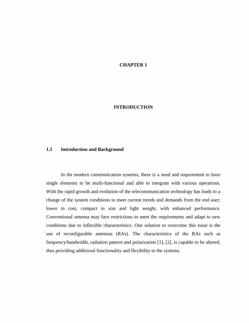
1.1 Introduction and Background
In the modern communication systems, there is a need and requirement to have
single elements to be multi-functional and able to integrate with various operations.
With the rapid growth and evolution of the telecommunication technology has leads to a
change of the system conditions to meet current trends and demands from the end user;
lower in cost, compact in size and light weight, with enhanced performance.
Conventional antenna may face restrictions to meet the requirements and adapt to new
conditions due to inflexible characteristics. One solution to overcome this issue is the
use of reconfigurable antennas (RAs). The characteristics of the RAs such as
frequency/bandwidth, radiation pattern and polarization [1], [2], is capable to be altered,
thus providing additional functionality and flexibility to the systems.
2
The transmissions of the radio signal paths travelling from transmitter to receiver
regularly experience the reflection/refraction phenomena caused by obstacles and
obstructions such as buildings, vehicles and surrounding natures. For an indoor and
confined environment, the occurrences of the reflection/refraction become more crucial
and challenging due to wall, equipment and furniture. This phenomena might affect the
transmitted signal, thus causing the signal to add up constructively or destructively and
vary with different polarization and time while reaching at the receiver [3]. Accordingly,
at particular occasions, the effective and reliable communication could be loss as the
received signal may decrease and drop below the acceptable value. Therefore, one of the
solutions to overcome this problem of multipath fading effect is by using single antenna
that capable of offering various types of polarization modes. Polarization reconfigurable
antennas (PRAs) are attractive due to the ability to control and switch the polarization
between linear polarization (LP), left-hand circular polarization (LHCP) or right-hand
circular polarization (RHCP). Besides reducing the fading effect, this type of diversity
provides another several advantages such as immune to the interference and minimizing
the polarization loss factor that eventually help to ensure the communication reliability.
The use of dual-polarized antenna [4–6] has been applied to several modern
telecommunication applications for improving reception quality. In using this method,
losses due to polarization mismatch can be reduced. The dual port antennas design can
be achieved by co-locating orthogonal polarization together on the similar design. To
further enhance the antenna performance, reconfigurable antenna is an effective
solution. Although the antenna is excited with fixed dual polarization antenna, it is also
capable of exciting between orthogonal LPs or orthogonal circular polarizations (CPs).
Hence, instead of exciting with dual-polarized fix polarization, both polarizations also
can be switched for selecting the best channel condition for that particular scenario and
environment.
3
A lot of peoples nowadays have used modern communication services in their
daily life routines, thus increase the demand and need for higher data rate and capacity
in the transmissions. One of the technologies that able to provide capacity improvement
is the use of multiple antennas at transmitter and receiver ends, known as Multiple-
Input-Multiple-Output (MIMO) systems. Compared to traditional single-input single-
output and single-input multiple-output systems, MIMO systems is higher diversity and
ability to mitigate multipath fading, which provide higher capacity performance. This
leads to more modern wireless communication systems to shift towards MIMO in order
to accommodate the demand from the end users. MIMO system is capable of realizing
higher throughput without required more bandwidth (BW) and additional power [7].
MIMO system is one of the key and important technologies for the future
wireless communication system, such as Third-Generation Partnership Project Long
Term Evolution (3GPP LTE), Worldwide Interoperability for Microwave Access
(WiMAX), and International Mobile Telecommunications-Advanced (IMT-Advanced).
The principal concept of the MIMO is to exploit and make use of space for enhancing
the transmission quality and efficiency, consequently able to increase the data rates.
Traditionally, MIMO system adopted space separated antenna to avoid mutual coupling
between antenna elements [8]. However, for limited space MIMO systems, the mutual
coupling between the adjacent antennas becomes more crucial, which could restrict and
reduces the system performances [9].
To further enhance the overall performance and increase the speeds of the
MIMO system, several techniques are being used such as advanced diversity schemes,
smart antenna/beam forming, and new modulation technique such as space shift keying.
Moreover, the link quality and reliability can be improved through employing RAs. The
diversity special features, such as polarization and pattern, are exploited to increase the
signal-to-noise ratio (SNR), which consequently improve the channel capacity [10].
4
1.2 Problem Statements
The revolution of the wireless communication technology has leads to the change
of the system requirement and environmental conditions in order to meet the current
demand. However, the inability of the antenna to accommodate and adapt to new
operation scenario or feature, such as dealing with limited and confined volume space
environment, can limit the system performance. Hence, having multifunctional antennas
or reconfigurable antenna will provide additional level of functionality and capability in
any particular wireless communication system. Conventional antenna design will face
restrictions in following the new trends since the antenna characteristics are inflexible
and fixed.
The capacity improvement in MIMO by using spatial diversity like spatial
multiplexing, transmit diversity or receive diversity are subject to enough and
availability of space [11]. Even though the spatial diversity are extremely potential to
increase capacity through space-separated technique, but this technique is not suitable
for space-limited MIMO applications such as mobile terminal, compact base station or
portable access point due to space is not an advantage to be exploit [12]. Benefits of
multiple channels are difficult to be obtained by using spatial diversity due to space
limitation. In addition, a physically separation distance about half wavelength is required
between two elements in order to have acceptable mutual coupling [13], which result in
unsuitable for space-limited MIMO applications.
In space-limited MIMO system, it is relatively challenging to accomplish great
performance by employing conventional antenna. Due to this limitation, reconfigurable
antenna with polarization diversity is used to enhance the performance of MIMO system
without required extra space, bandwidth and power. Hence, space resources can be save
and utilize by co-locating orthogonal polarizations on the similar structure, which make
5
the designed antenna more compact in size. Furthermore, it is extra cost saving
compared to physically separated antenna [14]. However, the main challenge is to obtain
sufficient isolation between two ports, whilst maintaining good impedance matching
with desired polarization sense.
Although the utilization of space is enormously significant and highly potential
to improve the channel capacity of the MIMO systems, how to design the antenna for
the space-limited MIMO application with efficiently use the space resources is still
needed to be further studied and investigated. Moreover, there is also a requirement for
increased functionality within a confined volume which leads to a burden on today‟s
wireless communication systems. Therefore, this project will focus on to design and
study the effect of the reconfigurable antenna with polarization diversity in space-limited
MIMO system.
1.3 Research Motivations
The topic is very significance as there are a lot of research currently has been
done in improving and enhancing the capacity. According to Shannon-Hartley theorem,
increase in bandwidth can increase the capacity. However, the disadvantages is
bandwidth is very limited resources and costly. Besides that, the degree of modulation
can be increased, but, it has the limitation. The use of reconfigurable antenna has been
identified capable to increase the SNR, consequently improve the capacity.
6
The study can give the performance comparison of the MIMO systems when
using reconfigurable antenna and non-reconfigurable antenna. The ability of the antenna
to reconfigure into various type of polarization modes; LP, LHCP, RHCP and slanted
LP, can be exploited to increase the SNR. In addition, the comparison is also made for
space-separation MIMO and space-limited MIMO application. By co-locating
orthogonal polarization on the similar structure, it could save cost and occupied less
space, which make it suitable for space-limited MIMO applications such as portable
access points. An investigation and study is carried out to determine the percentage of
channel capacity improvement offered by proposed antenna by exploiting polarization
diversity feature.
1.4 Research Objectives
The main focus of this research is to study on the effect and impact of deploying
PRAs at the receiver end for space limited MIMO application. The impact is calculated
in term of percentage of channel capacity improvement offered by the polarization
reconfigurable antenna when comparing with non-reconfigurable antenna and space-
separation MIMO. In order to accomplish this, the main focus is divided into 3 major
objectives:
1) To design and develop a single port polarization reconfigurable antenna.
2) To design and develop a dual port polarization reconfigurable antenna.
3) To conduct the field experiment on channel capacity of 2 x 2 MIMO in an indoor
environment.
7
1.5 Scope of the Research
The scopes began with gathering information, review and study the literature of
related topics such as concept of polarization reconfigurable antenna, theory of MIMO
system, and technique to achieve reconfigurability feature. It is also including technique
of biasing such as type of switches and biasing components. This work aimed the
antenna to be operated in WLAN frequency band (2.4-2.5 GHz). The antennas should
have the capability to reconfigure the polarization between LP, LHCP and RHCP. The
microstrip circular patch antenna is selected to be used as radiator for both single and
dual port design to ensure fair comparison between techniques and for easier analysis.
Moreover, the size of circular shaped antenna is slightly smaller than rectangular.
Slit perturbation and alteration of the feeding networks techniques are being used
to design the single port antenna. It is much easier to achieve circular polarization for
single feed antenna through perturbed and modified the antenna physical. Using this
method, the switches and biasing network is inserted on the radiating element.
Meanwhile, for the alteration of the feeding network, the CPW slotline feeding structure
is selected because of easy integration with RF switches and uncomplicated of the
biasing circuitry as it is placed on the ground plane. Furthermore, the special
characteristic of CPW to accommodate odd and even mode is exploited to establish the
second port on the similar structure, thus make it more compact and suitable for space-
limited MIMO applications. To achieve the polarization reconfigurability features, PIN
diodes are chosen as switches due to the lower in cost and its simplicity in biasing as
compared to other type of switches.
8
The antenna is simulated using Computer Simulation Technology Microwave
Studio and the optimization is done by using parametric study. The optimized design is
fabricated and measured to validate the antenna. The single and dual port antenna is
tested in the experiment of the 2 x 2 MIMO in real indoor environment. The effect of the
designed polarization reconfigurable antenna in term of channel capacity is studied and
analysed.
1.6 Outline of the Thesis
This thesis presents a progressive study on PRAs in space-limited MIMO
applications and their potential advantages. This thesis is structured as follows.
Chapter 1 states the research background, problem statement, research objectives
and scope of the research.
Chapter 2 reviews important concepts and theories of the RAs, particularly on
PRAs. It touches in details of the technique in designing polarization diversity antenna
and technique of biasing. This chapter also introduces the RF components, the selection
of type of switches, and the theory of the polarization. Lastly, it explains on the
background of the MIMO and the concept of the channel capacity measurement for
evaluating performances of the MIMO systems.
9
Chapter 3 starts off with discussions of the research methodology. This chapter
presents the flow of the works and describes the three main stages in order to achieve the
research objectives. It explains on the design and simulation. In addition, it also
discusses on the fabrication and measurement procedures. Finally, this chapter explains
the method of capacity measurement and setup.
Chapter 4 presents on the design of the single port PRAs. Two techniques use are
slits perturbation and feeding network modification. It discusses the design approach,
switch configurations and design mechanism for both techniques. Method in achieving
fixed operating frequency and widening the axial ratio (AR) bandwidth is also presented.
The measurement results is comparing with simulation results.
Chapter 5 presents on the design approach, mechanism and configurations of the
dual-ports PRAs. Good isolations are achieved by utilizing the odd and even mode of the
CPW structure. The simulated and measured are fully documented and presented. The
discrepancies are discussed and analysed.
Chapter 6 shows the result of the measurement and capacity analysis. It also
explains in details the experimentation setup and scenario. MATLAB software is used
for analysis and theoretical capacity evaluation. The hardware implementation is
presented. The performance is reported in cumulative distribution function graph.
Finally, Chapter 7 summarizes the thesis with conclusions on all major findings
and contributions. It discusses possible improvements and suggestions for future work.
184
REFERENCES
[1] L. Nan and W. An-guo, “A novel tree-shaped antenna with reconfigurable
radiation pattern,” in Asia-Pacific International Symposium on Electromagnetic
Compatibility, 2010, pp. 1333–1336.
[2] N. Ramli, M. T. Ali, and A. L. Yusof, “Reconfigurable microstrip stacked array
antenna with frequency and pattern characteristics,” Prog. Electromagn. Res. C,
vol. 49, pp. 47–58, 2014.
[3] B. S. Collins, “Polarization diversity antennas for compact base stations,”
Microw. J., vol. 43, no. 1, pp. 76–88, 2000.
[4] C.-H. Lee, S.-Y. Chen, and P. Hsu, “Isosceles triangular slot antenna for
broadband dual polarization applications,” IEEE Trans. Antennas Propag.,
vol. 57, no. 10, pp. 3347–3351, 2009.
[5] C. Deng, P. Li, and W. Cao, “A high-isolation dual-polarization patch antenna
with omnidirectional radiation patterns,” IEEE Antennas Wirel. Propag. Lett.,
vol. 11, pp. 1273–1276, 2012.
[6] G.-L. Wu, W. Mu, G. Zhao, and Y.-C. Jiao, “A novel design of dual circularly
polarized antenna fed by L-strip,” Prog. Electromagn. Res., vol. 79, pp. 39–46,
2008.
[7] M. Mowlér, M. B. Khalid, and B. Lindmark, “Reconfigurable monopole array
with MEMS switches for MIMO systems,” in IEEE Antennas and Propagation
Society International Symposium, 2008, pp. 1–4.
[8] V. Eiceg, H. Sampath, and S. Catreux-Erceg, “Dual-polarization versus single-
polarization MIMO channel measurement results and modeling,” IEEE Trans.
Wirel. Commun., vol. 5, no. 1, pp. 28–33, Jan. 2006.
185
[9] X. Wang, W. Chen, Z. Feng, and H. Zhang, “Compact dual-polarized antenna
combining printed monopole and half-slot antenna for MIMO applications,” in
IEEE Antennas and Propagation Society International Symposium, 2009, no. 1,
pp. 1–4.
[10] A. Grau, H. Jafarkhani, and F. De Flaviis, “A reconfigurable multiple-input
multiple-output communication system,” IEEE Trans. Wirel. Commun., vol. 7,
no. 5, pp. 1719–1733, May 2008.
[11] A. Lozano, S. Member, and N. Jindal, “Transmit diversity vs . spatial
multiplexing in modern MIMO systems,” IEEE Trans. Wirel. Commun., vol. 9,
no. 1, pp. 186–197, 2010.
[12] V. R. Anreddy and M. A. Ingram, “Capacity of measured Ricean and Rayleigh
indoor MIMO channels at 2.4 GHz with polarization and spatial diversity,” in
IEEE Wireless Communications and Networking Conference, 2006, pp. 946–951.
[13] Y. Li, J. Zheng, and Z. Feng, “Latest progress in MIMO antennas design,”
INTECH Open Access Publisher. Croatia:In Tech, pp. 1–6, 2012.
[14] C. B. Dietrich, K. Dietze, J. R. Nealy, and W. L. Stutzman, “Spatial, polarization,
and pattern diversity for wireless handheld terminals,” IEEE Trans. Antennas
Propag., vol. 49, no. 9, pp. 1271–1281, 2001.
[15] B. A. Cetiner, E. Akay, E. Sengul, and E. Ayanoglu, “A MIMO system with
multifunctional reconfigurable antennas,” Antennas Wirel. Propag. Lett., vol. 5,
no. 1, pp. 463–466, 2006.
[16] B. Y. Toh, R. Cahill, and V. F. Fusco, “Understanding and measuring circular
polarization,” IEEE Trans. Educ., vol. 46, no. 3, pp. 313–318, 2003.
[17] R. Antenna, “Polarization.” .
[18] S.-J. Wu and T.-G. Ma, “A wideband slotted bow-tie antenna with reconfigurable
CPW-to-slotline transition for pattern diversity,” IEEE Trans. Antennas Propag.,
vol. 56, no. 2, pp. 327–334, 2008.
[19] W. Wu, B.-Z. Wang, and S. Sun, “Pattern reconfigurable microstrip patch
antenna,” J. Electromagn. Waves Appl., vol. 19, no. 1, pp. 107–113, 2005.
[20] W. Kang, J. Park, and Y. Yoon, “Simple reconfigurable antenna with radiation
pattern,” Electron. Lett., vol. 44, no. 3, pp. 182–183, 2008.
186
[21] Y. B. Chen, X. F. Liu, Y. C. Jiao, and F. S. Zhang, “A frequency reconfigurable
CPW-fed slot antenna,” J. Electromagn. Waves Appl., vol. 21, no. 12,
pp. 1673–1678, 2007.
[22] S.-L. S. Yang, A. A. Kishk, and K.-F. Lee, “Frequency reconfigurable U-slot
microstrip patch antenna,” IEEE Antennas Wirel. Propag. Lett., vol. 7,
pp. 127–129, 2008.
[23] J. Ouyang, F. Yang, Z. P. Nie, and Z. Q. Zhao, “A novel frequency reconfigurable
microstrip antenna for wideband application,” J. Electromagn. Waves Appl.,
vol. 22, pp. 1403–1410, 2008.
[24] J. Malik, S. Member, A. Patnaik, S. Member, and M. V Kartikeyan, “Novel
printed MIMO antenna with pattern and polarization diversity,” IEEE Antennas
Wirel. Propag. Lett., vol. 14, pp. 739–742, 2015.
[25] H. T. Chattha, Y. Huang, S. J. Boyes, and X. Zhu, “Polarization and pattern
diversity-based dual-feed planar inverted-F antenna,” IEEE Trans. Antennas
Propag., vol. 60, no. 3, pp. 1532–1539, 2012.
[26] J.-S. Row and C.-J. Shih, “Polarization-diversity ring slot antenna with frequency
agility,” IEEE Trans. Antennas Propag., vol. 60, no. 8, pp. 3953–3957, 2012.
[27] Z. Pengfei, L. I. U. Shizhong, C. Rongrong, and H. Xinglin, “A reconfigurable
microstrip patch antenna with frequency and circular polarization diversities,”
Chinese Journals Electron., vol. 25, no. 2, pp. 379–383, 2016.
[28] K. Chung, Y. Nam, T. Yun, and J. Choi, “Reconfigurable microstrip patch
antenna with switchable polarization,” ETRI J., vol. 28, no. 3, pp. 379–382,
Jun. 2006.
[29] Y. Sung, “A novel reconfigurable microstrip antenna with polarization diversity,”
Microw. Opt. Technol. Lett., vol. 52, no. 9, pp. 2053–2056, 2010.
[30] Y. J. Sung, T. U. Jang, and Y.-S. Kim, “A reconfigurable microstrip antenna for
switchable polarization,” IEEE Microw. Wirel. Components Lett., vol. 14, no. 11,
pp. 534–536, Nov. 2004.
[31] S.-H. Hsu and K. Chang, “A novel reconfigurable microstrip antenna with
switchable circular polarization,” IEEE Antennas Wirel. Propag. Lett., vol. 6,
pp. 160–162, 2007.
187
[32] Y. J. Sung, “Reconfigurable patch antenna for polarization diversity,” IEEE
Trans. Antennas Propag., vol. 56, no. 9, pp. 3053–3054, Sep. 2008.
[33] S. Raghavan, D. S. Kumar, and M. S. K. Kumar, “Reconfigurable patch slot
antenna for circular polarization diversity,” Int. J. Microw. Opt. Technol., vol. 3,
no. 4, pp. 419–425, 2008.
[34] F. Yang and Y. Rahmat-Samii, “A reconfigurable patch antenna using switchable
slots for circular polarization diversity,” IEEE Microw. Wirel. Components Lett.,
vol. 12, no. 3, pp. 96–98, 2002.
[35] M. Yu, L. Ye, Y. Chen, L. Zhang, H. Liu, and Q. H. Liu, “Circular patch
microstrip antenna with reconfigurable polarization capability,” in IEEE
International Conference on Communication Problem-Solving, 2015,
vol. 361005, pp. 314–315.
[36] J.-H. Lim, G.-T. Back, and T.-Y. Yun, “Polarization-diversity cross-shaped patch
antenna for satellite-DMB systems,” ETRI J., vol. 32, no. 2, pp. 312–318,
Apr. 2010.
[37] M. M. Bilgiç and K. Yegin, “Polarization reconfigurable patch antenna for
wireless sensor network applications,” Int. J. Distrib. Sens. Networks, vol. 2013,
p. 5 pages, 2013.
[38] C.-C. Wang, L.-T. Chen, and J.-S. Row, “Reconfigurable slot antennas with
circular polarization,” Prog. Electromagn. Res., vol. 34, pp. 101–110, 2012.
[39] D.-H. Hyun, J.-W. Baik, and Y.-S. Kim, “Compact reconfigurable circularly
polarised microstrip antenna with asymmetric cross slots,” Microw. Opt. Technol.
Lett., vol. 50, no. 8, pp. 2217–2219, 2008.
[40] D.-H. Hyun, J.-W. Baik, S. H. Lee, and Y.-S. Kim, “Reconfigurable microstrip
antenna with polarisation diversity,” Electron. Lett., vol. 44, no. 8, pp. 509–511,
2008.
[41] Y. Lin, J. Yang, and J. Row, “A design for suspended patch antenna with
switchable polarization,” Microw. Opt. Technol. Lett., vol. 58, no. 6,
pp. 1333–1337, 2016.
188
[42] M. S. Nishamol, V. P. Sarin, D. Tony, C. K. Aanandan, P. Mohanan, and K.
Vasudevan, “An electronically reconfigurable microstrip antenna with switchable
slots for polarization diversity,” IEEE Trans. Antennas Propag., vol. 59, no. 9,
pp. 3424–3427, Sep. 2011.
[43] C.-H. Lai, T.-Y. Han, and T.-R. Chen, “Circularly-polarized reconfigurable
microstrip antenna,” J. Electromagn. Waves Appl., vol. 23, pp. 195–201, 2009.
[44] P.-Y. Qin, A. R. Weily, Y. J. Guo, and C.-H. Liang, “Polarization reconfigurable
U-Slot patch antenna,” IEEE Trans. Antennas Propag., vol. 58, no. 10,
pp. 3383–3388, Oct. 2010.
[45] A. Khidre, K. Lee, F. Yang, and A. Z. Elsherbeni, “Circular Polarization
Reconfigurable Wideband E-Shaped Patch Antenna for Wireless Applications,”
IEEE Trans. Antennas Propag., vol. 61, no. 2, pp. 260–263, 2013.
[46] E. A. Soliman, W. De Raedt, and G. A. E. Vandenbosch, “Reconfigurable slot
antenna for polarization diversity,” J. Electromagn. waves Appl., vol. 23,
pp. 905–916, 2009.
[47] Y. B. Chen, Y. C. Jiao, and F. S. Zhang, “Polarization reconfigurable CPW-fed
square slot antenna using pin diodes,” Microw. Opt. Technol. Lett., vol. 49, no. 6,
pp. 1233–1236, 2007.
[48] W. M. Dorsey, A. I. Zaghloul, and M. G. Parent, “Perturbed square-ring slot
antenna with reconfigurable polarization,” IEEE Antennas Wirel. Propag. Lett.,
vol. 8, pp. 603–606, 2009.
[49] W.-S. Yoon, S.-M. Han, S. Pyo, J. Lee, I.-C. Shin, and Y.-S. Kim,
“Reconfigurable circularly polarized microstrip antenna on a slotted ground,”
ETRI J., vol. 32, no. 3, pp. 468–471, Jun. 2010.
[50] M. Boti, L. Dussopt, and J.-M. Laheurte, “Circularly polarised antenna with
switchable polarisation sense,” Electron. Lett., vol. 36, no. 18, pp. 1518–1519,
2000.
[51] X.-X. Yang, B.-C. Shao, F. Yang, A. Z. Elsherbeni, and B. Gong, “A polarization
reconfigurable patch antenna with loop slots on the ground plane,” IEEE
Antennas Wirel. Propag. Lett., vol. 11, pp. 69–72, 2012.
189
[52] M. H. Amini, H. R. Hassani, and S. M. A. Nezhad, “A single feed reconfigurable
polarization printed monopole antenna,” in European Conference on Antennas
and Propagation, 2012, pp. 1–4.
[53] W. Cao, B. Zhang, A. Liu, T. Yu, D. Guo, and K. Pan, “A reconfigurable
microstrip antenna with radiation pattern selectivity and polarization diversity,”
IEEE Antennas Wirel. Propag. Lett., vol. 11, pp. 453–456, 2012.
[54] J. Huang, K.-F. Tong, and C. Baker, “A new polarization reconfigurable
microstrip antenna for diversity array,” in IEEE Radar Conference, 2008, pp. 1–4.
[55] W. B. Wei, Q. Z. Liu, Y. Z. Yin, and H. J. Zhou, “Reconfigurable microstrip
patch antenna with switchable polarization,” Prog. Electromagn. Res., vol. 75,
pp. 63–68, 2007.
[56] X. Ding, R. Wang, Y. Wen, B. Wang, and D. E. Anagnostou, “A novel
polarization reconfigurable antenna based on transmission line theory,” in IEEE
International Symposium on Antennas and Propagation, 2015, vol. 2,
pp. 2375–2376.
[57] J.-S. Row, W.-L. Liu, and T.-R. Chen, “Circular polarization and polarization
reconfigurable designs for annular slot antennas,” IEEE Trans. Antennas Propag.,
vol. 60, no. 12, pp. 5998–6002, 2012.
[58] T. Fukusako, N. Kitamura, and N. Mita, “Circularly polarized reconfigurable
patch antenna using Y-branched feed circuit,” in IEEE Antennas and Propagation
Society International Symposium, 2005, vol. 2B, pp. 597–600.
[59] T. Fukusako, N. Kitamura, and N. Mita, “Design of patch antenna with
switchable circular polarization using a branched feed circuit,” Microw. Opt.
Technol. Lett., vol. 48, no. 1, pp. 9–12, 2006.
[60] S. Hu, J. Pan, and J. Qiu, “A compact polarization diversity MIMO microstrip
patch antenna array with dual slant polarizations,” in IEEE Antennas and
Propagation Society International Symposium, 2009, pp. 1–4.
[61] W.-J. Liao, S.-J. You, and H.-T. Chou, “A polarization reconfigurable patch array
antenna,” in IEEE International Conference on Wireless Information Technology
and Systems, 2010, vol. 1, no. 1, pp. 1–4.
190
[62] S. Lin, Y. Lin, C. Li, and Y. Lee, “Patch Antenna with Reconfigurable
Polarization,” in Asia Pacific Microwave Conference Proceedings, 2011, vol. 1,
pp. 634–637.
[63] M. H. Amini and H. R. Hassani, “Compact polarisation reconfigurable printed
monopole antenna at 2.4 GHz,” Electron. Lett., vol. 49, no. 17, pp. 1049–1050,
Aug. 2013.
[64] Cheng P. Wen, “Coplanar waveguide: A surface strip transmission line suitable
for nonreciprocal gyromagnetic device applications,” IEEE Trans. Microw.
Theory Tech., vol. MTT-17, no. 12, pp. 1087–1090, 1969.
[65] Nihad I. Dib and L. P. B. Katehi, Theoritical characterization of coplanar
waveguide transmission lines and discontinuities. 1992.
[66] R. K. Saini and S. Dwari, “A broadband dual circularly polarized square slot
antenna,” IEEE Trans. Antennas Propag., vol. 64, no. 1, pp. 290–294, 2016.
[67] S. Chaimool and P. Akkaraekthalin, “CPW-fed antennas for WiFi and WiMAX,”
Wireless Communication Research Group, Faculty of Engineering, 2008.
[68] Y. Li, Z. Zhang, W. Chen, and Z. Feng, “Polarization reconfigurable slot antenna
with a novel compact CPW-to-slotline transition for WLAN application,” IEEE
Antennas Wirel. Propag. Lett., vol. 9, pp. 252–255, 2010.
[69] Y. Li, Z. Zhang, Z. Feng, M. F. Iskander, and R. Li, “Polarization reconfigurable
slot antenna for WLAN application,” in IEEE Antennas and Propagation Society
International Symposium, 2010, no. 1, pp. 1–4.
[70] Y. Li, Z. Zhang, W. Chen, and M. F. Iskander, “A dual-polarization slot antenna
using a compact CPW feeding structure,” IEEE Antennas Wirel. Propag. Lett.,
vol. 9, pp. 191–194, 2010.
[71] K. Ei, Z. Zhang, W. Chen, and Z. Feng, “A compact CPW-fed circular patch
antenna with pattern and polarization diversities,” Microw. Opt. Technol. Lett.,
vol. 53, no. 5, pp. 968–972, 2011.
[72] Y. Chen, F. Zhang, M. Wang, J. Li, and Y. Chen, “A spiral slot antenna with
reconfigurable CPW-to-slotline transition for polarization diversity,” Prog.
Electromagn. Res. C, vol. 45, pp. 73–85, 2013.
191
[73] E. A. Soliman, S. Brebels, E. Beyne, and G. A. E. Vandenbosch, “Circularly
polarised aperture antenna fed by CPW and built in MCM-D technology,”
Electron. Lett., vol. 35, no. 4, pp. 250–251, 1999.
[74] C.-Y. Huang and K.-L. Wong, “Coplanar waveguide-fed circularly polarized
microstrip antenna,” IEEE Trans. Antennas Propag., vol. 48, no. 2, pp. 328–329,
2000.
[75] H. Aïssat, L. Cirio, J. Grzeskowiak, J. M. Laheurte, and O. Picon, “CPW-fed
patch antenna with switchable polarization sense,” in European Microwave
Conference, 2005, pp. 1–4.
[76] H. Aïssat, L. Cirio, M. Grzeskowiak, J.-M. Laheurte, and O. Picon,
“Reconfigurable circularly polarized antenna for short-range communication
systems,” IEEE Trans. Microw. Theory Tech., vol. 54, no. 6, pp. 2856–2863,
2006.
[77] G. Ruvio, M. J. Ammann, and Z. N. Chen, “Wideband reconfigurable rolled
planar monopole antenna,” IEEE Trans. Antennas Propag., vol. 55, no. 6,
pp. 1760–1767, 2007.
[78] C. J. Panagamuwa, A. C. Chauraya, and J. (Yiannis) C. Vardaxoglou, “Frequency
and beam reconfigurable antenna using photoconducting switches,” IEEE Trans.
Antennas Propag., vol. 54, no. 2, pp. 449–454, Feb. 2006.
[79] S. Nikolaou, B. Kim, and P. Vryonides, “Reconfiguring antenna characteristics
using PIN diodes,” in European Conference on Antennas and Propagation, 2009,
pp. 3748–3752.
[80] Y. Cao, S. W. Cheung, and T. I. Yuk, “A simple planar polarization reconfi
gurable monopole antenna for GNSS / PCS,” IEEE Trans. Antennas Propag.
Ante, vol. 63, no. 2, pp. 500–507, 2015.
[81] S. V Shynu, G. Augustin, C. K. Aanandan, P. Mohanan, and K. Vasudevan,
“Design of compact reconfigurable dual frequency microstrip antennas using
varactor diodes,” Prog. Electromagn. Res., vol. 60, pp. 197–205, 2006.
[82] C. G. Christodoulou, D. Anagnostou, and V. Zachou, “Reconfigurable
multifunctional antennas,” in IEEE International Workshop on Antenna
Technology Small Antennas and Novel Metamaterials, 2006, pp. 176–179.
192
[83] L. A. Starman, J. R. Reid, R. T. Webster, and J. L. Ebel, “RF MEMS Switches for
Antenna Applications,” in International Congress & Exposition on Experimental
& Applied Mechanics Conference, 2004, pp. 1–8.
[84] P. D. Grant, M. W. Denhoff, and R. R. Mansour, “A comparison between RF
MEMS switches and semiconductor switches,” in International Conference on
MEMS, NANO and Smart Systems, 2004, pp. 515–521.
[85] I. Yeom, J. Choi, S. Kwoun, B. Lee, and C. Jung, “Analysis of RF front-end
performance of reconfigurable antennas with RF switches in the far field,” Int. J.
Antennas Propag., vol. 2014, pp. 1–14, 2014.
[86] C. G. Christodoulou, Y. Tawk, S. A. Lane, and S. R. Erwin, “Reconfigurable
antennas for wireless and space applications,” Proc. IEEE, vol. 100, no. 7,
pp. 2250–2261, Jul. 2012.
[87] I. H. Idris, M. R. Hamid, M. H. Jamaluddin, M. K. A. Rahim, J. R. Kelly, and H.
A. Majid, “Single- , dual- and triple-band frequency reconfigurable antenna,”
Radioengineering, vol. 23, no. 3, pp. 805–811, 2014.
[88] M. F. Ismail, M. K. A. Rahim, and H. A. Majid, “The investigation of PIN diode
switch on reconfigurable antenna,” in IEEE International RF and Microwave
Conference, 2011, no. December, pp. 234–237.
[89] H. A. Majid, M. K. A. Rahim, M. R. Hamid, and M. F. Ismail, “Frequency
reconfigurable microstrip patch-slot antenna with directional radiation pattern,”
Prog. Electromagn. Reseach, vol. 144, pp. 319–328, 2014.
[90] S.-B. Byun, J.-A. Lee, J.-H. Lim, and T.-Y. Yun, “Reconfigurable ground-slotted
patch antenna using PIN diode switching,” ETRI J., vol. 29, no. 6, pp. 832–834,
Dec. 2007.
[91] T. Sabapathy, M. F. Jamlos, R. B. Ahmad, M. Jusoh, M. I. Jais, and
M. R. Kamarudin, “Electronically reconfigurable beam steering antenna using
embedded RF PIN based parasitic arrays (ERPPA),” Prog. Electromagn. Res.,
vol. 140, pp. 241–261, 2013.
[92] M. Z. A. A. Aziz and M. K. a. Rahim, “Wireless MIMO channel capacity using
double stage diversity technique,” Wirel. Pers. Commun., vol. 85, no. 4,
pp. 2067–2081, Jul. 2015.
193
[93] M. F. A. Kadir, M. K. Suaidi, and M. Z. A. Aziz, “MIMO beamforming netwok
having polarization diversity,” in European Conference on Antennas and
Propagation, 2009, pp. 1743–1747.
[94] J. P. Kermoal, L. Schumacher, K. I. Pedersen, P. E. Mogensen, and
F. Frederiksen, “A stochastic MIMO radio channel model with experimental
validation,” IEEE J. Sel. Areas Commun., vol. 20, no. 6, pp. 1211–1226, 2002.
[95] A. M. Abdin, “Design of dual-polarization stacked arrays for wireless
communications,” Prog. Electromagn. Reseach, vol. 4, no. 4, pp. 409–412, 2008.
[96] K. Masuda, “Correlation of MIMO and its evaluation,” in IEEE International
Symposium on Antennas and PropagationAntennas and Propagation Society,
2005, pp. 355–358.
[97] J. P. Kermoal, P. E. Mongensen, S. H. Jensen, J. B. Andersen, F. Frederiksen,
T. B. Sorensen, and K. I. Pedersen, “Experimental investigation of multipath
richness for multi-element transmit and receive antenna arrays,” in IEEE
Conference Proceedings on Vehicular Technology, 2000, pp. 2004–2008.
[98] Alex Gershman and Nikos Sidiropoulos, Space-time processing for MIMO
communications. England: Wiley, 2005, p. 388.
[99] D. Piazza, P. Mookiah, M. D‟Amico, and K. R. Dandekar, “Experimental analysis
of pattern and polarization reconfigurable circular patch antennas for MIMO
systems,” IEEE Trans. Veh. Technol., vol. 59, no. 5, pp. 2352–2362, 2010.
[100] P.-Y. Qin, Y. J. Guo, and C.-H. Liang, “Effect of antenna polarization diversity
on MIMO system capacity,” IEEE Antennas Wirel. Propag. Lett., vol. 9,
pp. 1092–1095, 2010.
[101] D. Piazza, N. J. Kirsch, A. Forenza, R. W. Health Jr, and K. R. Dandekar,
“Design and evaluation of a reconfigurable antenna array for MIMO systems,”
IEEE Trans. Antennas Propag., vol. 56, no. 3, pp. 869–881, 2008.
[102] H. K. Pan, G. Huff, T. Roach, Y. Palaskas, S. Pellerano, P. Seddighrad,
V. K. Nair, D. Choudhury, B. Bangerter, and J. T. Bernhard, “Increasing channel
capacity on MIMO system employing adaptive pattern / polarization
reconfigurable antenna,” in IEEE International Symposium on Antennas and
Propagation, 2007, pp. 481–484.
194
[103] F. Mubasher, S. Wang, X. Chen, and Z. Ying, “Study of reconfigurable antennas
for MIMO systems,” in IEEE International Workshop on Antenna Technology,
2010, pp. 1–4.
[104] J. F. Valenzuela-valdés, M. F. Manzano, and L. Landesa, “Deepening true
polarization diversity for MIMO system,” IEEE Antennas Wirel. Propag. Lett.,
vol. 11, pp. 933–936, 2012.
[105] J. F. Valenzuela-valdés, M. A. García-fernández, A. M. Martínez-gonzález, D. A.
Sánchez-hernández, S. Member, and A. M. Chambers, “Evaluation of true
polarization diversity for MIMO systems,” IEEE Trans. Antennas Propag.,
vol. 57, no. 9, pp. 2746–2755, 2009.
[106] J. R. Mosig, M. Yousefbeiki, and J. Perruisseau-Carrier, “A practical technique
for accurately modeling reconfigurable lumped components in commercial full-
wave solvers,” IEEE Antennas Propag. Mag., vol. 54, no. 5, pp. 298–303, 2012.
[107] Y. B. Chen, T. B. Chen, Y. C. Jiao, and F. S. Zhang, “A reconfigurable microstrip
antenna for switchable polarization,” J. Electromagn. Waves Appl., vol. 20,
no. 10, pp. 1391–1398, 2006.
[108] C. A. Balanis, Antenna Theory Analysis and Design, 3rd ed. New Jersey: Wiley,
2005.
[109] Microstrip Antenna Design Handbook. Artech House, 2001, p. 845.
[110] S. P. I. N. Diodes and C. Rf, Datasheet pin diode. 2011, pp. 1–12.
[111] J. M. Laheurte, H. Tosi, and J. L. Dubard, “Microstrip antenna controlled by p-i-n
diodes: Influence of the bias current on the antenna efficiency,” Microw. Opt.
Technol. Lett., vol. 33, no. 1, pp. 44–47, Apr. 2002.
[112] S. F. Roslan, M. R. Kamarudin, M. Khalily, and M. H. Jamaluddin, “An MIMO
rectangular dielectric resonator antenna for 4G applications,” IEEE Antennas
Wirel. Propag. Lett., vol. 13, pp. 321–324, 2014.
[113] J. Nasir, M. H. Jamaluddin, M. Khalily, M. R. Kamarudin, and I. Ullah, “Design
of an MIMO dielectric resonator antenna for 4G applications,” Wirel. Pers.
Commun., vol. 88, no. 3, pp. 525–536, 2016.
195
[114] M. Khalily, M. H. Jamaluddin, T. A. Rahman, J. Nasir, and M. R. Kamarudin,
“MIMO dielectric resonator antenna for LTE femtocell access point
applications,” in European Conference on Antennas and Propagation, 2015,
pp. 1–4.
[115] R. Kumar, R. V. S. R. Krishna, and N. Kushwaha, “Design of a compact
MIMO/diversity antenna for UWB applications with modified TH-like structure,”
Microw. Opt. Technol. Lett., vol. 58, no. 5, pp. 1181–1187, 2016.
[116] S. Pyo and Y. Sung, “Asymmetrical coupling feed of circularly polarized
microstrip antenna for bandwidth enhancement,” Microw. Opt. Technol. Lett.,
vol. 58, no. 7, pp. 1672–1675, 2016.
[117] A. Panahi, X. L. Bao, K. Yang, O. O. Conchubhair, and M. J. Amman, “A simple
polarization reconfigurable printed monopole antenna,” IEEE Trans. Antennas
Propag., vol. 63, no. 11, pp. 5129–5134, 2015.
[118] Y. Fan, Y. Cui, and R. Li, “Polarization reconfigurable omnidirectional antenna
using crossed dipoles,” in IEEE International Symposium on Antennas and
Propagation, 2015, pp. 2371–2372.
[119] A. A. Abdelaziz, “Bandwidth enhancement of microstrip antenna,” Prog.
Electromagn. Res., vol. 63, pp. 311–317, 2006.
[120] D. Heberling and C. Oikonomopoulos-Zachos, “On multiport antennas for
MIMO-systems,” in Loughborough Antennas & Propagation Conference, 2009,
pp. 65–70.
[121] D. Piazza, P. Mookiah, D. Michele, and K. R. Dandekar, “Pattern and polarization
reconfigurable circular patch for MIMO systems,” in European Conference on
Antennas and Propagation, 2009, pp. 1047–1051.
[122] A. Narbudowicz, X. Bao, and M. J. Ammann, “Dual circularly-polarized patch
antenna using even and odd feed-line modes,” IEEE Trans. Antennas Propag.,
vol. 61, no. 9, pp. 4828–4831, 2013.
[123] J. Hamalainen, R. Wichman, J.-P. Nuutinen, J. Ylitalo, and T. Jamsa, “Analysis
and measurement for indoor polarization MIMO in 5.25 GHz band,” in IEEE
Vehicular Technology Conference, 2005, pp. 252–256.