polarization measurement - hawthorne tech writer the polarization measurement antennas to the...
TRANSCRIPT
In Part 1 of this article, several applications for a precision, monopulse polarimeter were identified. Such a system is under development at the ESM Division of Watlrins-Johnson Company. The electromagnetic theory presented in Part 1 allows a better understanding of the performance improvements realized by the Watkins-Johnson approach to polarization measurement.
Polarization Measurement System The polarization measurement system discussed in the following pages is based on Watlrins-Johnson Company's line of microwave receiving and analysis systems, and is being developed in response to customer requirements for precision polarization measurement capability. It is intended to provide a powerful, flexible and accurate system in a compact, costeffective package. Although the system is directed toward ESM and ELINT applications, it could easily be adapted to other systems.
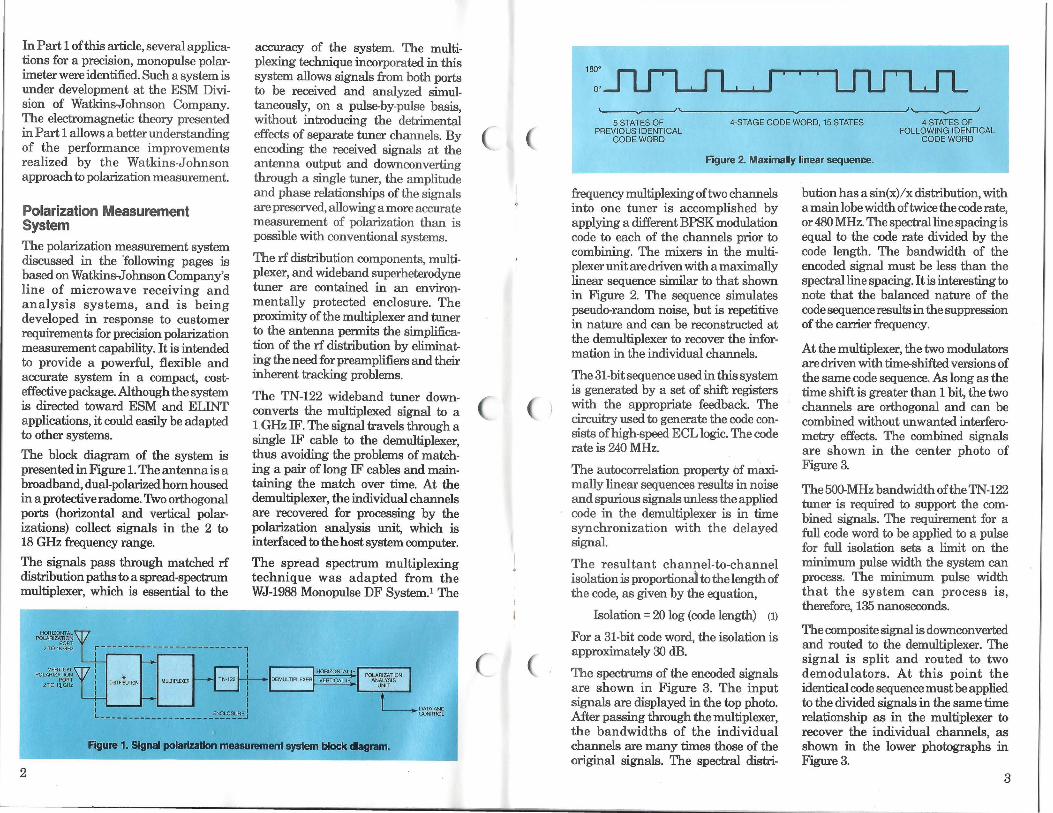
The block diagram of the system is presented in Figure 1. The antenna is a broadband, dual-polarized horn housed in a protective radome.'I\vo orthogonal ports (horizontal and vertical polarizations) collect signals in the 2 to 18 GHz frequency range.
The signals pass through matched rf distribution paths to a spread-spectrum multiplexer, which is essential to the
i .-----, ----------~--
L_~---==--
accuracy of the system. The multiplexing technique incorporated in this system allows signals from both ports to be received and analyzed simultaneously, on a pulse-by-pulse basis, without introducing the detrimental effects of separate tuner channels. By encoding the received signals at the antenna output and downconverting through a single tuner, the amplitude and phase relationships of the signals are preserved, allowing a more accurate measurement of polarization than is possible with conventional systems.
The rf distribution components, multiplexer, and wideband superheterodyne tuner are contained in an environmentally protected enclosure. The proximity of the multiplexer and tuner to the antenna permits the simplification of the rf distribution by eliminating the need for preamplifiers and their inherent traclring problems.
The TN-122 wideband tuner downconverts the multiplexed signal to a I .GHz IF. The signal travels through a single IF cable to the demultiplexer, thus avoiding the problems of matching a pair of long IF cables and maintaining the match over time. At the demultiplexer, the individual channels are recovered for processing by the polarization analysis unit, which is interfaced to the host system computer.
The spread spectrum multiplexing technique was adapted from the WJ-1988 Monopulse DF System.1 The
Figure 1. Signal polarization measurement system block diagram.
2
180'
O'
'----v----''------------------.J~ 5 STATES OF 4-STAGE CODE WORD, 15 STATES 4 STATES OF
PREVIOUS IDENTICAL FOLLOWING IDENTICAL CODE WORD CODE WORD
Figure 2. Maximally linear sequence.
frequency multiplexing of two channels into one tuner is accomplished by applying a different BPSK modulation code to each of the channels prior to combining. The mixers in the multiplexer unit are driven with a maximally linear sequence similar to that shown in Figure 2. The sequence simulates pseudo-random noise, but is repetitive in nature and can be reconstructed at the demultiplexer to recover the information in the individual channels.
The 31-bit sequence used in this system is generated by a set of shift registers with the appropriate feedback. The circuitry used to generate the code consists of high-speed ECL logic. The code rate is 240 MHz.
The autocorrelation property of maximally linear sequences results in noise and spurious signals unless the applied code in the demultiplexer is in time synchronization with the delayed signal.
The resultant channel-to-channel isolation is proportional to the length of the code, as given by the equation,
Isolation= 20 log (code length) (1)
For a 31-bit code word, the isolation is approximately 30 dB.
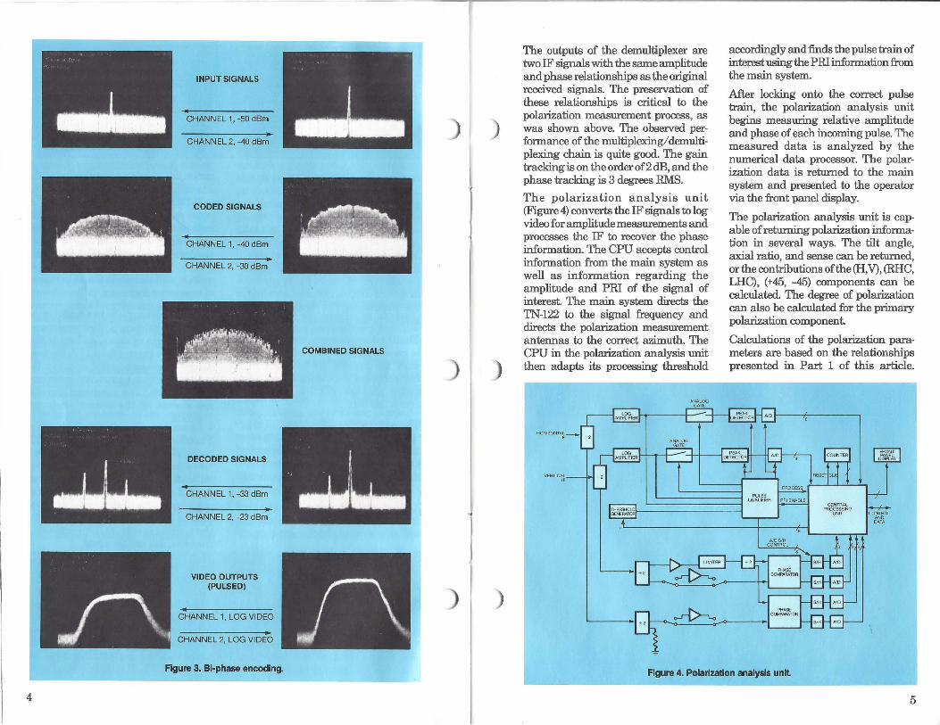
The spectrums of the encoded signals are shown in Figure 3. The input signals are displayed in the top photo. After passing through the multiplexer, the bandwidths of the individual channels are many times those of the original signals. The spectral distri-
bution has a sin(x)/ x distribution, with a main lobe width of twice the code rate, or 480 MHz. The spectral line spacing is equal to the code rate divided by the code length. The bandwidth of the encoded signal must be less than the spectral line spacing. It is interesting to note that the balanced nature of the code sequence results in the suppression of the carrier frequency.
At the multiplexer, the two modulators are driven with time-shifted versions of the same code sequence. As long as the time shift is greater than 1 bit, the two channels are orthogonal and can be combined without unwanted interferometry effects. The combined signals are shown in the center photo of Figure 3.
The 500-MHz bandwidth of the TN-122 tuner is required to support the combined signals. The requirement for a full code word to be applied to a pulse for full isolation sets a limit on the minimum pulse width the system can process. The minimum pulse width that the system can process is, therefore, 135 nanoseconds.
The composite signal is downconverted and routed to the demultiplexer. The signal is split and routed to two demodulators. At t his point the identical code sequence must be applied to the divided signals in the same time relationship as in the multiplexer to recover the individual channels, as shown in the lower photographs in Figure 3.
3
4
INPUT SIGNALS
CHANNEL 1, -50 dBm
CHANNEL 2, -40 dBm
CODED SIGNALS
CHANNEL 1, -40 dBm
CHANNEL 2, -30 dBm
DECODED SIGNALS
CHANNEL 1, -33 dBm
CHANNEL 2, -23 dBm
VIDEO OUTPUTS (PULSED)
CHANNEL 1, LOG VIDEO
CHANNEL 2, LOG VIDEO
Figure 3. Bi-phase encoding.
COMBINED SIGNALS
·.J....
) )
)
)
The outputs of the demultiplexer are two IF signals with the same amplitude and phase relationships as the original received signals. The preservation of these relationships is critical to the polarization measurement process, as was shown above. The observed performance of the multiplexing/ demultiplexing chain is quite good. The gain tracking is on the order of2 dB, and the phase tracking is 3 degrees RMS.
The polarization analysis unit (Figure 4) converts the IF signals to log video for amplitude measurements and processes the IF to recover the phase information. The CPU accepts control information from the main system as well as information regarding the amplitude and PRI of the signal of interest. The main system directs the TN-122 to the signal frequency and directs the polarization measurement antennas to the correct azimuth. The CPU in the polarization analysis unit then adapts its processing threshold
VERTICAL IF
~
accordingly and :finds the pulse train of interest using the PRI information from the main system.
After locking onto the correct pulse train, the polarization analysis unit begins measuring relative amplitude and phase of each incoming pulse. The measured data is analyzed by the numerical data processor. The polarization data is returned tQ the main system and presented to the operator via the front panel display.
The polarization analysis unit is capable of returning polarization information in several ways. The tilt angle, axial ratio, and sense can be returned, or the contributions of the (H,V), (RHC, LHC), (+45, -45) components can be calculated. The degree of polarization can also be calculated for the primary polarization component
Calculations of the polarization parameters are based on the relationships presented in Part 1 of this article.
CON"TBOL AND DATA
Figure 4. Polarization analysis unil
5
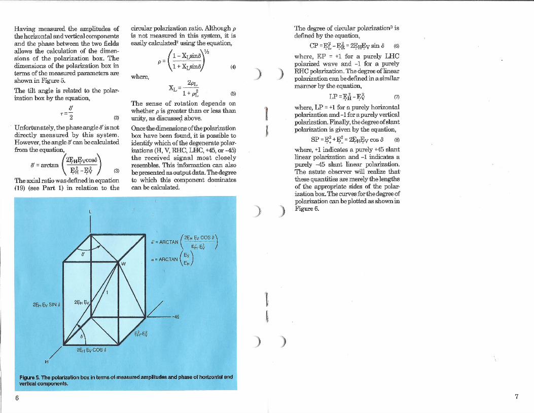
Having measured the amplitudes of the horizontal and vertical components and the phase between the two fields allows the calculation of the climensions of the polarization box. The dimensions of the polarization box in t.erms of the measured paramet.ers are shown in Figure 5.
The tilt angle is related t,o the polarization box by the equation,
{f
r=2 (2)
Unfortunat.ely, the phase angle fl is not directly measured by this syst.em. However, the angle ff can be calculated from the equation,
{f = arctan (2~tt~vcosa\ ~11-~f ) (3)
The axial ratio was defined in equation (19) (see Part 1) in relation t,o the
2~H ~vSIN o
/ 2~H ~vCOS o
H
circular polarization ratio. Although p is not measured in this syst.em, it is easily calculated2 using the equation,
where,
(1- XI,Sin6\½
P = 1 + XI,Sin8 / (4)
2pL
XL= 1 + pf (5)
The sense of rotation depends on whether p is great.er than or less than unity, as discusse<j above.
Once the dimensions of the polarization box have been found, it is possible to identify which of the degenerat.e polarizations (H, V, RHC, LHC, +45, or -45) the received signal most closely resembles. This information can also be presented as output data. The degree t,o which this component dominates can be calculated.
o' = ARCTAN ( 2~H Ev cos()) E~- Et
o=ARCTAN (~)
Figure 5. The polarization box in tenns of measured amplitudes and phase of horizontal and vertical components.
6
)
·1
,i
'fi
'
)
)
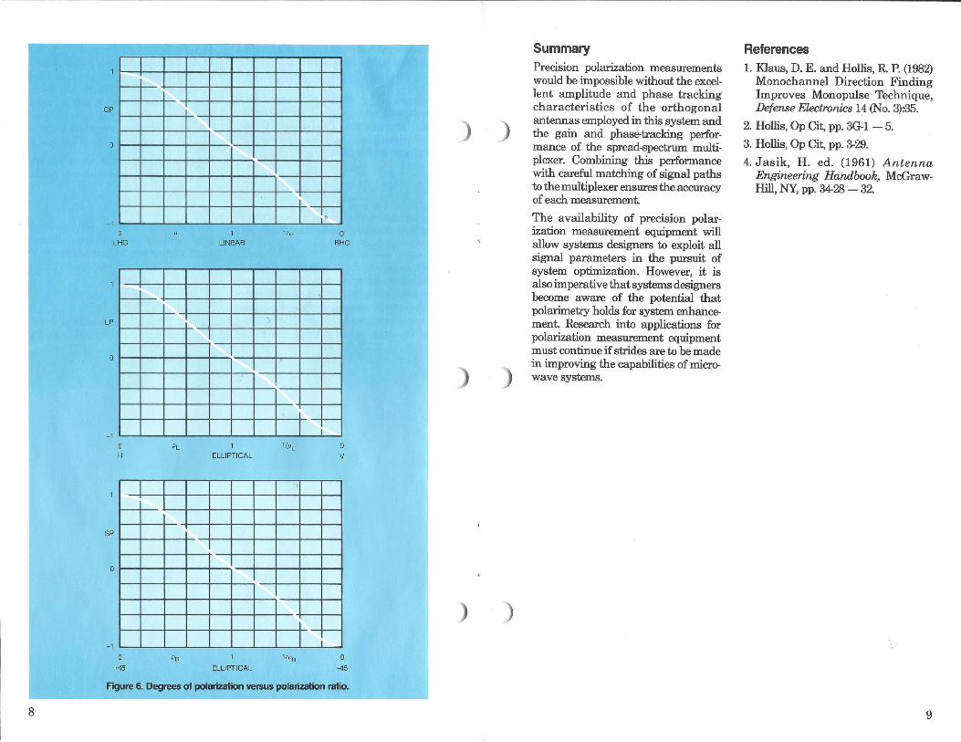
The degree of circular polarization3 is defined by the equation,
CP = ~l -~~ = ~Hlj:v sin o (6)
where, EP = + 1 for a purely LHC polarized wave and -1 for a purely RHC polarization. The degree of linear polarization can be defined in a similar manner by the equation,
LP =EfI-Ef (7)
where, LP = + 1 for a purely horizontal polarization and -1 for a purely vertical polarization. Finally, the degree of slant polarization is given by the equation,
SP = ~! + ~= = ~H~V cos 6 (8)
where, + 1 indicates a purely +45 slant linear polarization and -1 indicates a purely -45 slant linear polarization. The astut.e observer will realize that these quantities are merely the lengths of the appropriat.e sides of the polarization box. Thecurvesforthedegreeof polarization can be plott.ed as shown in Figure 6.
7
8
CP
0
-1
LHC
LP
0
- 1
SP
0
-1
0
H
0
+45
PL
Po
1 LINEAR
ELLIPTICAL
ELLIPTICAL
1/p
'
1/pL
1/po
I -
I -
-i'"
0 RHC
-I
0 V
I_ ,__ I
0
-45
F'igure 6. Degrees of polarization versus polarization ratio.
)
)
Summary Precision polarization measurements would be impossible without the excellent amplitude and phase tracking characteristics of the orthogonal antennas employed in this system and the gain and phase-tracking performance of the spread-spectrum multiplexer. Combining this performance with careful matching of signal paths to the multiplexer ensures the accuracy of each measurement.
The availability of precision polarization measurement equipment will allow systems designers to exploit all signal parameters in the pursuit of system optimization. However, it is also imperative that systems designers become aware of the potential that polarimetry holds for system enhancement. Research into applications for polarization measurement equipment must continue if strides are to be made in improving the capabilities of microwave systems.
References 1. Klaus, D. E. and Hollis, R. P. (1982)
Monochannel Direction Finding Improves Monopulse Technique, Defense Ekctronics 14 (No. 3):-35.
2. Hollis, Op Cit, pp. 3~ 1 - 5.
3. Hollis, Op Cit, pp. 3-29.
4. Jasik, H. ed. (1961) Antenna Engineering Handbook, . McGrawHill, NY, pp. 34-28 - 32.
9
Author:
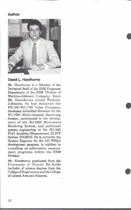
David L. Hawthorne Mr. Hawthorne is a Member of the Technical Staff of the ESM Programs Department of the ESM Division of Watkins-Johnson Company. Since Mr. Hawthorne joined WatkinsJ ohnson, he has designed the PR-100/WJ-1780 Video Processor, developed embedded firmware for the WJ-1890 Multi-channel Receiving System, participated in the developmen t of the WJ-8969 Microwave Receiving System, and performed system engineering on the WJ-1945 Field Analysis/Measurement ELINT System (FAMES). He is currently the System Engineer for the AN /WSQ-5 development program, in addition to consulting on polarization measuremen t programs within the ESM Division.
Mr. Hawthorne graduated from the University of Illinois. He holds bachelor of science degrees from the College of Engineering and the College of Liberal Arts and Sciences.
10
WATKINS-JOHNSON COMPANY 3333 HILLVIEW AVENUE PALO ALTO, CA 94304-1204 (415) 493-4141
ADDRESS CORRECTION REQUESTED
BULK RATE U.S. POSTAGE
PAID PERMIT NUMBER
173 MILPITAS
CALIFORNIA
• WATKINS-JOHNSON
United States
CALIFORNIA
Watkins-Johnson 3333 Hillview Avenue Palo Alto, 94304-1204 Telephone: (415) 493-4141
Watkins-Johnson 2525 North First Street San Jose, 95131-1097 _Telephone: (408) 435-1400
Watkins-Johnson 440 Kings Village Road Scotts Valley, 95~081 Telephone: (408) 438-2100
Watkins-Johnson 214 East Gutierrez Street Santa Barbara, 93101-1705 Telephone: (805) 965-1 013
lntemational
UNITED KINGDOM
Watkins-Johnson Dedworth Road Oakley Green Windsor, Berksh ire SL4 4LH Telephone: (0753) 869241 Telex: 847578 Cable: WJUKW-WINDSOR
Facility Locations
ITALY
MARYLAND
Watkins-Johnson 700 Quince Orchard Road Gaithersburg, 20878-1794 Telephone: (301) 948-7550
Watkins-Johnson 8530 Corridor Road Savage, 20763 Telephone: (301) 497-3900
NORTH CAROLINA
Watkins-Johnson 100 West Powell Road Fuquay-Varina, 27526-9399 Telephone: (919) 552-6161
GERMANY, FEDERAL REPUBLIC OF
Watkins-Johnson S.p.A. Piazza G. Marconi 25 00144 Roma-EUR Telephone: 592 45 54
Watkins-Johnson Keferloher Strasse 90 8000 Muenchen 40 Telephone: (089) 35 97 038 Telex: 509401 591 25 15
Telex: 612278 Cable: WJ ROM I
Cable: WJDBM-MUENCHEN
The Watkins-Johnson Tech-notes is a bi-monthly periodical circulated to educational institutions, engineers, managers of companies or government agencies, and technicians. Individuals may receive issues of Tech-notes by sending their subscription request on company letterhead, stating position and nature of business to the Editor, Tech-notes, at Watkins-Johnson's Palo Alto, California address. Permission to reprint articles may also be obtained by writing the Editor.
COPYRIGHT @ 1988 WATKINS-JOHNSON COMPANY Printed in U.S.A.