poland the netherlands italy france croatia bulgaria · • aggressive dissemination of results and...
TRANSCRIPT

RCHES
EXECUTIVE SUMMARY REPORT
ASSESSMENT AND REHABILITATION OF CENTRAL EUROPEAN HIGHWAY STRUCTURES
http://arches.fehrl.org
FEHRLFEHRL - Blvd. de la Woluwe, 421200 Brussels - BelgiumPhone: +32 2 775 82 45Fax: +32 2 775 82 54E-mail: [email protected]://arches.fehrl.org
FOR MORE INFORMATION
UNIVERSITAT POLITÈCNICA DE CATALUNYA
Poland The Netherlands Italy France Croatia Bulgaria
Austria Estonia Ireland Slovenia Croatia
Spain Slovenia Czech Republic The Netherlands Switzerland

Executive Summary Report
ii
RCHES
6th Framework Programme
Theme: Mobility & Transport, Safety & Security
Started: 1 September 2006
Duration: 36 months
Budget: 2.94m EUR
RCHES
The overall goal of the project ARCHES (Assessment and Rehabilitation of Central European Highway Structures) was to reduce any gaps in the standard of highway infrastructure between Central and Eastern European Countries (CEEC), particularly New Member States (NMS), and the rest of the EU. This key problem was addressed by a combined approach:
• developingmoreappropriatetoolsandproceduresto avoid unnecessary interventions (repairs/replacements) in structures;
• prevent the development of corrosion by simpler,and less expensive techniques, implement faster, more cost-effective, and longer lasting rehabilitation techniques (repair or strengthening) of sub-standard and unsafe bridges;
• aggressivedisseminationofresultsandgeneralbestpractice to the key stakeholders.
ARCHES Executive Summary ReportMay 2010

iii
iii
Hlavním cílem projektu ARCHES je snížit rozdíl mezi úrovní dopravní infrastruktury ve středoevropských a východoevropských zemích (CEEC), se zaměřením na nové členské země Evropské unie (NMS), a úrovní dopravní infrastruktury v ostatních členských zemích
Evropské unie. Tato problematika bude řešena kombinací následujících přístupů:• rozvojvhodnýchnástrojůapostupů,kterébyzabraňovalyzbytečnýmzásahům
do konstrukcí (opravy, rekonstrukce);• předcházení rozvoje koroze pomocí jednoduchých a finančně nenáročných
technologií; zavedení rychlejších, cenově výhodných a dlouhotrvajících technologií (oprav nebo zpevňování) nevyhovujících a potencionálněnebezpečných mostů;
• rozšiřovánívýsledkůazávěrečnýchdoporučenímezizainteresovanéorganizacea orgány jednotlivých zemí.
Scopo del progetto ARCHES è di ridurre il divario esistente fra il livello delle infrastrutture autostradali dell’Europa Centrale (CEEC), in particolare i Nuovi Stati Membri (NMS), ed il resto dell’Europa. Questo problema sarà affrontato con un approccio combinato:
• sviluppandonuovistrumentieprocedureperevitareinterventidiriparazionemanutenzione sulle strutture;
• prevenendo lo sviluppo della corrosione mediante l’impiego di tecnichesemplici ed economiche;
• implementando durature e rapide tecniche di riparazione/manutenzione,economicamente vantaggiose, dei ponti che presentano bassi livelli di sicurezza;
•disseminandorisultatie‘bestpractice’aglistakeholderchiave.
El principal objetivo de ARCHES es reducir las diferencias en el nivel de servicio existentes entre las infraestructuras viarias (puentes) de los países del Centro y Este de Europa (CEEC), en particular los nuevos Estados Miembros (NMS), y el resto de la Unión Europea.
Ello se hará en base a la siguiente metodología:• desarrollandométodosyherramientasavanzadasdeevaluaciónymonitorización
estructural para evitar intervenciones ( reparaciones/ sustituciones) innecesarias;• evitando la corrosión de armaduras mediante técnicas más simples, baratas,
fáciles de aplicar y más efectivas, así como técnicas de reparación más durables; • diseminando intensamente los resultados del proyecto y las guías de buena
práctica entre las Administraciones responsables.
L’objectif du projet ARCHES est de réduire l’écart au niveau des infrastructures routières entre les pays d’Europe centrale et de l’est (CEEC), particulièrement les nouveaux états membres (NMS), et le reste de l’Union Européenne. Ce problème clé sera traité au
moyen d’une approche combinée:• développer des outils et des procédures plus appropriés afin d’éviter des
interventions inutiles (remises en état/remplacements) sur les structures;• prévenir le développement de la corrosion par des techniques plus simples et
moins coûteuses, mettre en œuvre des techniques de réhabilitation (remise en état ou renforcement) plus rentables et plus durables, pour les ponts non conformes aux normes actuelles et dont la sécurité est insuffisante;
• dissémination proactive des résultats et des règles de l’art aux intervenants clés.
ARCHESi üldine eesmärk on vähendada maanteeinfrastruktuuri standardite erinevusi Kesk- ja Ida-Euroopa riikide, eriti uute liikmesriikide, ning ülejäänud Euroopa Liidu riikide vahel. Antud probleemile lähenetakse kombineeritult:
• luuakse sobivamaid vahendeid ja võtteid, et vältida asjatuid sekkumisi(parandustöödvõiväljavahetamine)rajatistesse;
• takistatakse korrosiooni teket lihtsamate ja odavamate meetodite abil,juurutatakse standardile mittevastavate ja ohtlike sildade remondiks kiiremaid, tulusamaid ja kauemkestvaid taastusmeetodeid (parandustööd võitugevdamine);
• levitatakse agressiivselt tulemusi ja üldisi häid tavasid puudutavat teavetpeamistele huvirühmadele.
Het doel van ARCHES is de kloof te verkleinen in het niveau van snelweginfrastructuur tussen Centraal- en Oosteuropese landen (CEEC), en in het bijzonder de Nieuwe Lidstaten (NMS), en de rest van de EU. Dit sleutelprobleem zal worden benaderd met een
gecombineerde aanpak:• ontwikkelen van geschiktere gereedschappen en procedures om onnodige
interventies (reparatie/vervanging) aan constructies te voorkomen;• deontwikkelingvancorrosie tevoorkomendooreenvoudigerengoedkopere
technieken en snellere, meer kosteneffectieve en duurzamere herstelmethoden (reparatie of versterken) in te voeren voor onvoldoende funtionerende en
onveilige bruggen; • agressieve disseminatie van resultaten en best practice naar de belangrijkste
stakeholders.
Opći cilj projekta ARCHES je povećati standard prometne infrastrukture zemalja Istočne Europe, posebice novih članica Europske Unije, odnosno smanjiti razlike u nivou kvalitete i sigurnosti na prometnicama Istočne i Centralne Europe. Taj ključni
problem će se sagledavati s više stajališta:• razvojem prihvatljivijih metoda i procedura za ocjenu stanja postojećih
konstrukcija, kako bi se izbjegli nepotrebni popravci i zamjene postojećih konstrukcija;
• sprečavanjem razvoja korozije i dotrajavanja konstrukcija primjenom novih- bržih, ekonomičnijih i trajnijih, metoda za zaštitu i popravak dotrajalih i nesigurnih konstrukcija/mostova u postojećoj infrastrukturi;
• snažnoširenjerezultataprojektaiiskustvadovodećihinteresnihgrupa.
Das Hauptziel von ARCHES ist es, die Straßeninfrastruktur der Zentral- und Osteuropäischen Länder, insbesondere der Neuen EU-Mitgliedsstatten, an den vorhandenen Standard der restlichen EU-Länder anzupassen. Dieser Problematik wird durch einen
kombinierten Ansatz entgegengewirkt: • Entwicklung von passenden Werkzeugen und Verfahren, um Eingriffe
(Instandsetzungs- oder Erhaltungsmaßnahmen) in die Infrastruktur gezielt steuern zu können;
• Minimierung von Korrosion durch einfachere und kosteneffizientereMaßnahmen; Implementierung schnellerer, kosteneffizienterer und langfristiger Instandhaltungs- bzw. Instandsetzungs-Maßnahmen für Substandard- bzw. für beschädigte Brücken;
• Proaktive Verteilung der Ergebnisse und Vermarktung von Best Practices anwichtige Stakeholder.
Glavni cilj projekta ARCHES je zmanjšati razkorak v stanju cestne infrastrukture med srednje in vzhodnoevropskimi državami, še posebno novimi članicami Evropske unije na eni, ter razvitimi evropskimi državami na drugi strani. V ta namen bo projekt s
kombiniranim pristopom:• izpopolnjeval orodja in postopke za preprečevanje nepotrebnih posegov
(obnov/zamenjav) na objektih;• razvijalmetode zapreprečevanje razvoja korozije z enostavnejšimi, cenejšimi,
učinkovitejšimi in dolgotrajnejšimi postopki rehabilitacije (obnov/ojačitev) poškodovanih objektov;
• širilinobjavljalrezultateinizkušnjemedlastnikiinupravljavciinfrastrukture
Podstawowym celem Projektu “Ocena stanu i metody napraw drogowych obiektów inżynierskich w Europie Centralnej (ARCHES)” jest zniwelowanie różnicy w standardach technicznych drogowych obiektówinżynierskichpomiędzykrajami‘starej’UniiEuropejskiej,
a krajami Europy Środkowej i Centralnej, ze szczególnym uwzględnieniem Nowych Krajów Członkowskich UE. Podstawowymi działaniami w ramach ARCHES będą:• opracowanie odpowiednich instrumentów i procedur oceny stanu obiektów
pozwalających na lepsze zarządzanie środkami przeznaczonymi na utrzymanie obiektów drogowych;
• opracowanieprostszychitańszychtechnologiizabezpieczeniaantykorozyjnegoobiektów oraz wprowadzenie szybkich, tanich i trwałych technologii napraw i wzmacniania zniszczonych lub niepewnych mostów;
• szerokie rozpowszechnianie wyników prac i doświadczeń wśród wszystkichzainteresowanych.
Крайната цел на проекта ARCHES е да се намали разликата в стандарта за пътната инфраструктура между страните от Централна и Източна Европа (CEEC), особено новите страни-членки, и останалите Европейски страни. Този основен
проблем ще бъде разглеждан с помощта на комбиниран подход:• разработваненапо-подходящиинструментиипроцедуризаизбягванена
ненужните намеси (ремонти/ подмени) в конструкциите;• предотвратяване развитието на корозия чрез по-прости и по-евтини
технологии; внедряване на по-бързи, по-ефективни по отношение наразходи и по-дълготрайни технологии за рехабилитация (ремонт илиусилване)намостове,коитонеотговарятнастандартитеисаопасни;
• разпространяване и налагане на резултатите и основните най-добрипрактики до заинтересованите страни.

Executive Summary Report
iv
RCHES
iv
Main author: Tomasz Wierzbicki, IBDiMContributers: All WP LeadersReviewed by: Adewole Adesiyun, FEHRL, Monika Kowalska-Sudyka, IBDiM, Ales Znidaric, ZAGDesign: Valerie Henry, FEHRL
© 2010, FEHRL
ALL RIGHTS RESERVED. This report contains material protected under International and Federal Copyright Laws and Treaties. Any unauthorized reprint or use of this material is prohibited. No part of this report may be reproduced or transmitted in any form or by any means, electronic or mechanical, including photocopying, recording, or by any information storage and retrieval system without express written permission from the author.

v
v
Project CoordinatorIBDiMMr.TomaszWierzbickiE-mail: [email protected]: +48 (22) 675 49 83Instytutowa 103-302Warsaw,Poland
WorkPackageleadersWP1TomaszWierzbicki,[email protected]
WP2JoanR.Casas,[email protected] Aljoša Šajna, [email protected]
WP4MarekŁagoda,[email protected]é,[email protected],[email protected]
CONTENTS
Introduction.............................................................................................................................................6
WP2 Structural Assessment and Monitoring....................................................................................8Load assessment.........................................................................................................................................................................8
Static effects of traffic................................................................................................................................................................8
Dynamic effects of traffic.........................................................................................................................................................9
Capacity assessment................................................................................................................................................................11
WP3 Prevention of corrosion............................................................................................................14Validationandapplicationofcorrosionresistantsteelreinforcement..................................................................14
Steel specimens in pore solution......................................................................................................................................15
Steel embedded in concrete specimens...........................................................................................................................16On site exposure – establishment of test site................................................................................................................17
Recommendations................................................................................................................................................................18Development and application of cathodic protection (CP) systems......................................................................18
TestfieldinSlovenia................................................................................................................................................................19
TestfieldinPoland...................................................................................................................................................................20
Numerical calculations for CP...............................................................................................................................................20Development/modificationofcorrosionmonitoringsystem.................................................................................21
WP4 Strengthening with FRP glued strips ......................................................................................22
WP5 Ultra High Performance Fibre reinforced Concrete (UHPFRC) for rehabilitation of bridges - recent advances in NMS and CEEC..................................................................................24
Composite UHPFRC-concrete structures.......................................................................................................................24Ultra High Performance Fibre reinforced Concrete (UHPFRC)...................................................................................25Advances in cast-on site UHPFRC technology..............................................................................................................26Optimization of rheology......................................................................................................................................................27First application in Slovenia - Log Čezsoški bridge.........................................................................................................29
Project Results..................................................................................................................................31

Executive Summary Report
6
RCHES
IntroductIon
The Sixth Framework Program ARCHES, (Assessment and Rehabilitation of Central European Highway Structures) was realised within the Sustainable Surface Transport area of the European Commission Research Activity. Since
September 2006, 12 partners from all around Europe (including the Central and Eastern European Countries of the EU15 (CEEC) and the New Member States of the EU10) had the chance to work together on this Project. It must be mentioned that most of the Partners are members of the Forum of European National Highway Research Laboratories (FEHRL), which also was the initiative body of the Project proposal in 2006. More than two years were dedicated to literaturestudying,basicexperimentsandcomprehensivelaboratoryandtheoreticalinvestigations.Thelast,andfinalyear of the project was devoted to practical experiments put into the real life of highway structures.
One has to remember that the strategic objective of the project was to reduce, in a sustainable way, the gap in the standard of highway structures between the CEEC and the rest of the EU. The idea was to achieve this by developing appropriate tools and procedures for a more efficient assessment, and faster, cost-effective, and long lasting rehabilitations (by reparations or strengthening) of sub-standard highway structures.
Toachieveitsscientificandtechnologicalgoals,ARCHESfocusedonstructuralassessmentandmonitoring,strategiesto prevent deterioration and optimum rehabilitation of highway structures by complementary techniques. The project was organised in 4 technical work packages, with the following conceptual approach:
• Optimise the use of existing infrastructure through better safety assessment and monitoring procedures, which will avoid interventions, i.e., avoid unnecessarily replacing or rehabilitating structures that are already fulfillingtherequirements(WP2);
• Monitor and prevent corrosion of existing reinforcement and develop innovative new reinforcement materialsthatarehighlyresistanttocorrosion(WP3);
• Strengthentheinfrastructureofbridgesbymeansofbondedreinforcements(WP4);• Harden highway structures with Ultra High Performance Fibre Reinforced Concretes (UHPFRC) applied in
severelyexposedzonestodramaticallyincreasetheirdurability(WP5).
7
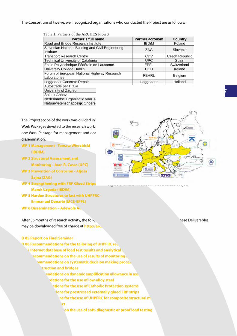
The Consortium of twelve, well recognized organisations who conducted the Project are as follows:
WP 6 Dissemination – Adewole Adesiyun (FEHRL)
After 36 months of research activity, the following Deliverables were prepared by the Partners. These Deliverables may be downloaded free of charge at http://arches.fehrl.org/.
D 05 Report on Final SeminarD 06 Recommendations for the tailoring of UHPFRC recipesD 07 Internet database of load test results and analytical calculationsD 08 Recommendations on the use of results of monitoring bridge safety assessment and maintenanceD 09 Recommendations on systematic decision making processes associated with maintenance of reconstruction and bridgesD 10 Recommendations on dynamic amplification allowance in assessment of bridgesD 11 Recommendations for the use of low-alloy steelD 12 Recommendations for the use of Cathodic Protection systemsD 13 Recommendations for prestressed externally glued FRP stripsD 14 Recommendations for the use of UHPFRC for composite structural membersD 15 Final activity reportD 16 Recommendations on the use of soft, diagnostic or proof load testing
Figure 1: Bodies involved in the ARCHES Project
The Project scope of the work was divided in four
WorkPackagesdevotedtotheresearchworkplus
oneWorkPackageformanagementandonefor
dissemination.
WP 1 Management - Tomasz Wierzbicki
(IBDiM)
WP 2 Structural Assessment and
Monitoring - Joan R. Casas (UPC)
WP 3 Prevention of Corrosion - Aljoša
Šajna (ZAG) WP 4 Strengthening with FRP Glued Strips - Marek Łagoda (IBDiM)WP 5 Harden Structures to last with UHPFRC - Emmanuel Denarié (MCS-EPFL)
Table 1: Partners of the ARCHES ProjectPartner’s full name Partner acronym Country
Road and Bridge Research Institute IBDiM Poland Slovenian National Building and Civil Engineering Institute ZAG Slovenia
Transport Research Centre CDV Czech Republic Technical University of Catalonia UPC Spain Ecole Polytechnique Fédérale de Lausanne EPFL Switzerland University College Dublin UCD Ireland Forum of European National Highway Research Laboratories FEHRL Belgium
Leggedoor Concrete Repair Laggedoor Holland Autostrade per l’Italia Autostrade Italy University of Zagreb UZ Croatia Salonit Anhovo SA Slovenia Nederlandse Organisatie voor Toegepast Natuurwetenschappelijk Onderzoek (TNO) TNO The
Netherlands

Executive Summary Report
8
RCHES
WP2 Structural aSSeSSment and monItorIngJ. caSaS (uPc) – WP 2 leader
Figure 2: Axle crane with a total weight of 1110 kN Figure 3: Low-loader vehicle with a total weight of 1450 kN
WPMEMBERS:ZAG: A. ŽNIDARIČ,A. ŠAJNA,T. BREMEC, I. LAVRIČ;AUTOSTRADE: L. PARDI; UCD: E. O’BRIEN, A. GONZALEZ, B. ENRIGHT, D. CANTERO; FEHRL: A. ADESIYUN; FEHRL-UMBRELLA:M.RALBoVSKy,S.DEIx,H.FRIEDL(AIT),I.BLAzHEV,G.HRISToV,K.KAMENoVA,I.yANKoV(CRBL),D.TKALCIC,S.JURIC(IGH) , A. CURY, C. CREMONA (LCPC), T. VEIKo, M. TRUU (TECER); CDV: J. STRyK; IBDiM: P. oLASzEK, J. CIEŚLA, M. BISKUP, J. SKAWIŃSKI, M.MAzANEK,T.BICzEL,A.WRzESIŃSKI,P.NUREK,RCzACHoWSKI.
LOAD ASSESSMENTEfforts were dedicated to a better understanding and appraisal of the traffic effects on bridges, both static and dynamic.
STATIC EFFECTS OF TRAFFICTrafficdatawasgatheredandisavailablefromWIMrecordscarriedoutinTheNetherlands,Poland,Slovenia,Slovakiaand the Czech Republic. This traffic data has been analysed and used to obtain, via simulation, the characteristic values of the traffic action for these aforementioned countries (4 New Member States (NMS) + The Netherlands for comparison). The results showed that the traffic action is significantly lower for all NMSwhen compared toWestern-Europeancountries. Also, in all cases, it is advised that the presence of unescorted exceptional vehicles (as those presented in theFigure2andFigure3)intothetrafficflow,mayproducecharacteristictrafficeffectsinbridgeshigherthanthosecaused by Load Model 1 (LM1) in the Eurocode for highway traffic actions in bridges. Therefore, important conclusions were derived regarding future traffic load models for new designs and also the traffic action to be considered in the assessment of existing bridges. In the case of new designs, it is advised that actual traffic loads in the Eurocode can be non-conservative if the presence of very heavy trucks (cranes and low-loaders) is not well controlled into the traffic flow.InthecaseoftheassessmentofexistingbridgesinCEEC,thefinalresulthasbeenthecalculation,viasimulation,of the characteristic load effects and the reduction factors by bridge class to be considered.

9
TheEurocodespecifiesthateachcountrymayapplyfactors (reductionfactors)tothestandardLM1toreflect localtraffic conditions.
Table 2 gives the average factors for all spans considered based on a 1000-year return period, with traffic volumes as measured at each site, in each country. These traffic volumes represent the most heavy traffic conditions within each country. Therefore, these factors can be combined with the appropriate factor depending on the truck volume as a percentageofwhatisusedinthesimulation,togiveasite-specificfactor.Asanexample,Table3givesfactorsfortheassessment of a bridge with 50% lower traffic volumes than the measured sites.
As seen, a more accurate and lower (around 25 %) value of the characteristic static traffic action to be used in the assessmentarederivedbasedonthereductionfactorsobtainedforeachspecificcountryandlocation.
DyNAMIC EFFECTS OF TRAFFICThe project reported more accurate values of the dynamic interaction between bridge and traffic that leads to a morerealisticassessment.ThevaluesoftheDynamicAmplificationFactor(DAF)andAllowanceDynamicRatio(ADR),definedastheratioofcharacteristictotalloadeffecttocharacteristicstaticloadeffecthavebeenobtainedconsideringthemostimportantvariablesinvolvedintheprocess:influenceofvehiclespeed,axleconfiguration,bridgetypeandspan-length, road condition, vehicle characteristics (vehicle suspension, vehicle/bridgemass ration, etc.), influenceof multi-presence of vehicles, presence of imperfections in the pavement ( bumps, damaged expansion joints, etc.). ARCHESreportedRecommendationsonhowtoobtainasite-specificADR(AllowanceDynamicRatio)usingnumericalsimulations.Guidelinesareprovidedonhowtobuildavehicle-bridgeinteraction(VBI)finiteelementmodelandhowtoobtainanADRforagivenroadprofile,trafficpopulationandreturnperiod.Also,recommendationsonhowtoobtainasite-specificADRusingbridgemeasurementsduetotrafficwerederived.
Lane Factors Site Mid-span moment Shear at supports Hogging moment
High
The Netherlands 0.99 1.07 1.08 Czech Republic 0.74 0.91 0.84
Slovenia 0.73 0.87 0.80 Poland 0.71 0.85 0.79
Slovakia 0.69 0.83 0.74
Low
The Netherlands 1.05 1.39 1.18 Czech Republic 0.88 1.19 1.00
Slovenia 0.84 1.15 0.97 Poland 0.82 1.10 0.93
Slovakia 0.80 1.09 0.92
Table 2: Alpha factors for design at full traffic volumes
Table 3: Alpha factors for assessment with 50% reduction in traffic
Lane Factors Site Mid-span moment Shear at supports Hogging moment
High
The Netherlands 0.88 0.96 0.96 Czech Republic 0.66 0.81 0.75
Slovenia 0.65 0.78 0.71 Poland 0.63 0.76 0.70
Slovakia 0.61 0.74 0.66
Low
The Netherlands 0.94 1.24 1.05 Czech Republic 0.79 1.06 0.89
Slovenia 0.75 1.02 0.86 Poland 0.73 0.98 0.83
Slovakia 0.71 0.97 0.82

Executive Summary Report
10
RCHES
Figure 4: Variation of Assessment Dynamic Ratio with Return Period and Road Profile
Figure 5: DAF recommandation versus Eurocode values
It has been demonstrated that exceptionally heavy vehicles, such as cranes and low-loaders, do not produce higher dynamic effects than those caused by a typical European 5-axle articulated truck. As presented in Figure 4, other important resultsderived fromtheprojectare thatas thereturnperiod increases, the influenceof theroadprofile(orvariabilityofADRwith theprofile)decreasesandhowrelativelyshortperiodof time (1month)canbeusedtogive a close estimate of ADR for longer periods. This is an important conclusion that decreases the computing efforts dramatically.
Finally, general recommendations are provided for assessment of 1-lane and 2-lane bridges (both moment and shear loadeffects)withISoroadclasses‘A’and‘B’(Figure5).Furtherreductionsindynamicallowancecanbeachieved,ifbetterknowledgeofthebridgeresponsewasacquiredthroughnumericalsimulationsandfieldtests.Infact,measurementson heavily trafficked motorways carried out within the ARCHES project, lasting from 2 weeks to 2 months showed, that the DAF decreased as a function of increasing weight of the loading events. The average DAF values for the extremely heavy vehicles (low-loaders or cranes) and for the multiple presence events with 2 heavy vehicles, was on all measured sites close to 1.
ThefinalresultinFigure5istheproposalofaDAFforassessmentofexistingbridgesasafunctionofthespan-lengththat is considerably lower (around 15 % ) and more accurate than the value proposed in most design Codes, in particular, theEurocode.Inthisway,bridgesratedasstructurallydeficientmaypasstheassessmentprocess.

11
Figure 6: View of Gameljne Bridge before testing, Ljubljana, Slovenia
Figure 7: Gameljne bridge during the proof-load test, Ljubljana, Slovenia
CAPACITy ASSESSMENTLoad tests on bridges have shown that in many cases bridges may resist much higher load than predicted by analytical assessments. This was the case of the bridge over the Gameljščica river in Gameljne, in Ljubljana, Slovenia (Figure 6), which is foreseen to be demolished, where proof load tests were performed as one of the tasks of ARCHES (Figure 7). Duringthetest,inadditionto“standard”parameters(load,deflection,deformationsonspecificpoints),theacousticactivity was also monitored. Although the maximum applied load exceeded the load limit (1000 kN vs. 260 kN) no significantdamagecouldbeobserved.
Thus, to explore more accurate methods for bridge response assessment, alternatives to the analytical methods, load testing procedures were investigated within ARCHES.
The concept of the so-called soft load test was introduced and the previous results from the SAMARIS project have been fully validated in ARCHES by the application of the test to more than 20 bridges. The test can be carried out without closing the bridge to traffic. As a result, recommendations concerning the main parameters of the test as the size of the sample (number of days of measurement) has been summarized. It was demonstrated how soft load testing can veryefficientlyacquiretherealinfluencelines(ofbendingmomentsespecially)andloaddistributionfactors,whichcan, in old bridges particularly, differ considerably from the theoretical ones. Experiences with soft load testing indicate thatdifferences(savings)betweentheoreticalandexperimental,influencelinesduringthebendingmomentcanbeespecially large on shorter and older single-span bridges, where boundary conditions are not known. Knowing the real behaviour(influencelinesandlanefactors)ofabridgehasimportantconsequencesforoptimizedbridgeassessment.

Executive Summary Report
12
RCHES
Whileusingtheoreticalsimplesupportedinfluencelinesandlanefactors,providesimportantreservesfordesignofnew bridges that can be used in the future if their condition deteriorates or the traffic conditions change, knowing the experimentalinfluencelinesconsiderablyoptimizessafetyassessmentofexistingbridges,andthuspreventsitfromprescribing unnecessary remedial measures on the bridge.
The characteristic total load effect is the nominal value to be used in the assessment to take into account the time period for the assessment ( 5, 10, 50,… years) and is, therefore, a key value in the assessment process. The calculation of such total load is done by multiplying the characteristic static load effect by the so-called Assessment Dynamic Ratio(ADR).ADRisdifferentfromDynamicAmplificationFactor(DAF)thatappliestopassagesofsingletrucks,and,therefore, is a more accurate dynamic factor to take into account the actual traffic load within a reference period in bridgeassessment.Infact,definingtheADR(AssessmentDynamicRatio)astheratiobetweenthetotaleffectandthestaticeffectoftrafficloadwithinadefinedtimeperiod,itisshownthatthevariabilityinADRnarrowsasreturnperiodincreases. As shown in Figure 4, the value corresponding to 1 month is close to the one corresponding to 1000 years returnperiod.Thefinalresultisaproposaltocombineindependentlyobservedvaluesofsite-specificcharacteristicstaticloadeffect(obtainedbysoft-loadtesting)andsite-specificADRforareturnperiodof1month(alsoobtainedfromsoft-loadtests)toobtainanaccuratevalueforsite-specificcharacteristictotalloadeffect.
ARCHES has also investigated the proof load testing. The proposal derived from the work developed into the project gives an answer to the two main questions involved in the use of such test:
1)Whatisthemaximumloadthatshouldbeappliedtothebridgeduringthetesttoguaranteethesafety(atapredefinedprobabilitylevel)whenthenormaldailytrafficactionwillbepresentinthebridge?2)Whenshouldtheloadingprocessstoptopreventthebridgefrombeingdamaged?Thanks to that, proof load testing can be viewed by the assessing engineer as a real alternative to the theoretical assessment.
Answeringthefirstquestion,acompletesetofproofloadfactorsfor5Europeancountries(TheNetherlands,CzechRepublic, Poland, Slovakia and Slovenia) have been calculated based on the actual traffic conditions in these countries as obtainedbyWIMtechniquesdevelopedwithinARCHES.Theyhavebeenobtainedfromacalibrationprocessbasedona reliability-based approach taking into account the uncertainties involved in loads and resistances. They are included in the project deliverables in the form of tables and charts and constitute a very easy and efficient way for the assessing engineertodefinethemaximumloadtoachieveduringtheexecutionofaproofloadtest.Thefollowingvariableshavebeen considered in the calibration process: safety level, span length, bridge type, traffic action, permanent additional load and available bridge documentation.
Concerning question 2, a proof load test was carried out on a real bridge close to the city of Barcza in Poland (Figure 8). The bridge is composed of precast prestressed concrete girders and was to be replaced in the near future. The bridge was loaded with concrete and steel weights (Figure 9) up to a load higher than the cracking load of the most loaded beam. At the same time, acoustic emission sensors and other monitoring equipment were used to follow the loading process.Theresultsoftheacousticemissionpredictedverypreciselythetimewhenthefirstcrackinthebeamwouldappear. AE was successful in predicting the maximum load level that can be introduced in the bridge in order not to damage the structure. Therefore, this monitoring technique has proved to be a very useful and promising tool. In this sense, ARCHES has effectively demonstrated in a real scale application that AE can be used in the monitoring of the execution of proof load tests.
Finally, the recommendations to elaborate a common Bridge Management System (BMS) for the NMS and CEEC have been proposed and presented in ARCHES. Recommendations include four topics: how to connect the current system to new BMS, what is the recommended structure of BMS, what are the main decision making processes within BMS and how to connect the BMS to decision systems of other assets.

13
Insummary,theconclusionsandrecommendationsobtainedinWP2ofARCHESprojectandreportedinDeliverableD07 – “Internet database of load test results and analytical calculations”, D08 – “Recommendations on the use of results of monitoring on bridge safety assessment and maintenance”, D09 – “Recommendations on the systematic decision makingprocessassociatedwithmaintenanceandreconstructionofbridges”,D10andD16completelyfulfilthemainobjectiveoftheWorkPackage:“toprovideguidelinesforimplementationofoptimisedbridgeassessmenttoolsinNMSand CEEC”.
Figure 8: Lateral view of Barcza bridge (Poland)
Figure 9: Proof load test of Barcza bridge.

Executive Summary Report
14
RCHES
WP3 PreventIon of corroSIon a. ŠaJna (Zag) – WP 3 leader
WPMEMBERS:ZAG: A.ŠAJNA,V.KUHAR,A.LEGAT,T.KoSEC,N.GARTNER,A.KRANJC; IGH: I.STIPANoVIĆ-oSLAKoVIĆ;AUTOSTRADE: L. PARDI, A. MERCALLI; UZ:D.BJEGoVIĆ,M.SERDAR;TNO: R. POLDER; IBDiM:A.KRÓLIKoWSKA,Ł.AUGUSTyŃSKI,L.KoMoRoWSKI,U.PASzEK;LBV: J.LEGGEDoR,G.SCHUTEN.
The objective of the Prevention of corrosion work package was to provide methods and techniques that will improve the durability of new and rehabilitated concrete structures, when corrosion induced deteriorations, if any, are taken
at an early stage.
WP3 of ARCHES project modified and implemented two modern rehabilitation/corrosion protection techniques,combined with new developments of corrosion monitoring systems. Following the achievements of previous research work (COST 521, COST 534, SAMARIS), three main directions of works were foreseen, i.e. the application of corrosion resistant steel reinforcement, implementation of cathodic protection (CP) systems and use of special Electrical Resistance probes for corrosion monitoring.
VALIDATION AND APPLICATION OF CORROSION RESISTANT STEEL REINFORCEMENTIt is well known that certain types of stainless steel are very resistive to corrosion in concrete environment, even when the concrete is highly contaminated with chlorides. However, due to high prices of these superior alloys (AISI 304, AISI 316), stainless steel reinforcement is generally only used in vital concrete structures exposed to aggressive marine environmentsorincertainspecificelementsexposedtode-icingsalts.yet,recentresultsindicatethatsomesteelswithlowercontentofalloyingelementsundercertainconditionsbehavesignificantlybetterthancommonlyusedblacksteel, even though their price is comparable.
The idea of the project was to compare stainless steels with lower alloying elements, to determine an optimal use of thesetypesofsteelreinforcementsandtodefinethelimitconditionswheretheirusemightstillbeefficient.InWP3ofARCHES project corrosion behaviour of seven different steel types was studied: two types of steel with lower content of alloying elements (TOP12 – 1.4003 and 204Cu – 1.4597), two grades of duplex steel (UGIGRIP 4362 – 1.4362 and SAE/UNS S3 2205 – 1.4462), two grades of stainless steel (AISI 304 – 1.4301 and AISI 304L – 1.4306). Ordinary black steel (B500B – 1.0439) was tested for comparison purposes.
In order to fully understand the behaviour of different types of corrosion resistant steels in concrete, research was divided into three steps: laboratory testing of steel specimens in pore solutions, laboratory testing of steel embedded into concrete specimens and on-site exposure of steel embedded concrete columns (establishment from test sites).
1515
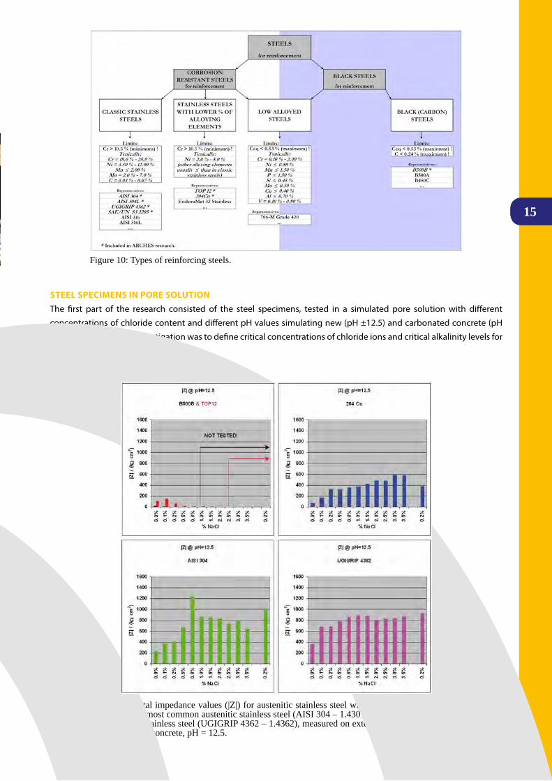
Figure 10: Types of reinforcing steels.
15
Figure 11: Total impedance values (|Z|) for austenitic stainless steel with lower Ni content (204Cu – 1.4597), the most common austenitic stainless steel (AISI 304 – 1.4301) and the most economical tested duplex stainless steel (UGIGRIP 4362 – 1.4362), measured on external surface in pore water simulating new concrete, pH = 12.5.
STEEL SPECIMENS IN PORE SOLUTIONThe first part of the research consisted of the steel specimens, tested in a simulated pore solutionwith differentconcentrations of chloride content and different pH values simulating new (pH ±12.5) and carbonated concrete (pH ±10.0).Theaimofthisinvestigationwastodefinecriticalconcentrationsofchlorideionsandcriticalalkalinitylevelsforevery type of steel.

Executive Summary Report
16
RCHES
The potentiodynamic technique was applied in the tests of fresh polished cross sections, whereas the tests of corrosion behaviour of external surfaces were studied using electrochemical impedance spectroscopy (EIS). Total impedance |Z| (Figure 11) was used as the criteria for determination of corrosion resistance of metals. The total impedance was estimated from Bode plots of impedance spectra as absolute impedance measured at the lowest measured frequency. The higher the value of total impedance the more corrosion resistant the tested material is.
STEEL EMBEDDED IN CONCRETE SPECIMENSIn the second part of the research, rebars were embedded in concrete creating reinforced concrete elements of different sizes: small cylindrical concrete specimens were submerged in NaCl solution, small prism shaped concrete specimens wereexposedtosaltspraychamber,mediumsizeconcretespecimenswithandwithoutanartificialtransversecrack,caused by bending of specimens (Figure 12b), were cyclically dried and wetted with NaCl solution, and larger concrete slabs were exposed to cyclical drying and wetting with NaCl solution.
Corrosion potential (Ecorr) and corrosion current (Icorr) values were used as the criteria for estimation of corrosion resistance of steel in concrete. These parameters were measured with various electrochemical techniques. Low corrosion potential (Figure 13, Figure 14 and Figure 15) indicates corrosion susceptibility. Corrosion potential of steel decreasing with time could indicate that this steel is active and that corrosion could occur. The values of corrosion potential that remain stable in time indicate that steel is still passive.
Corrosion current of steel (Figure 13, Figure 14) that is increasing with time could indicate that this steel is active and that corrosion could occur. Steels that have stable low values of corrosion current in time are treated to be passive as well.
16
Figure 12: a) Medium size concrete specimens with embedded rebars and electrical resistance (ER) probe, exposed to cyclic wetting with chloride solution from the top; b) Concrete specimens with embedded rebars and artificial cracks, exposed to cyclic wetting with chloride solution from the bottom.
a) b)
Figure 13: Corrosion potential and current density vs. time for different types of steel reinforcement embedded in small cylindrical concrete specimens, half submerged into a 3.5 % NaCl solution and electrochemically tested using linear polarization.

17
Figure 15: Corrosion potentials vs. time (Cu-CuSO4 half-cell) of the steel rebars in medium size concrete specimens with artificial transverse cracks.
17
Figure: 16 Location of test site.
Figure 14: Corrosion potential and current density vs. time for different types of steel reinforcement embedded in small prism shaped concrete specimens exposed to cycles of wetting, drying and spraying with 3.5 % NaCl solution in the salt spray chamber and measured periodically, using galvanostatic impulse method with half-cell measurement instrument.
ON SITE ExPOSURE – ESTABLISHMENT OF TEST SITEFor long-time investigations an exposure site was established in the real marine environment. The aim of the third part of research was to evaluate the corrosion behaviour of different types of steel reinforcement in real size elements and real environment.
Forfieldtestzone,sixtypesofreinforcingsteelwereembeddedinthecolumns,withthreecolumnsforeachtypeofreinforcing steel. All columns are reinforced with two reinforcing bars made from corrosion resistant steel and two from black steel. ER probes were installed at different heights of columns, enabling corrosion monitoring in different exposure conditions (submerged, splashing and atmospheric zone).
Exposure testing site is situated on the north Adriatic coast under Krk Bridge. Krk Bridge was built during the 1980’s and since then it has been exposed to marine environment. Due to the aggressive marine environment, it has been continuously affected by severe corrosion problems, mostly accumulated in the corrosion of reinforcement.

Executive Summary Report
18
RCHES
The columns were placed in one meter deep sea water, with 2 meters of columns rising above the sea level. Along the years, one third of the columns length will be constantly submerged in sea water, one third will be exposed to splashing and one third will be exposed to atmospheric conditions.
During exposure corrosion parameters will be monitored periodically. Monitoring will be performed with embedded ER probes (ARCHES task 3.3) and other NDT methods like galvanostatic pulse measurements.
RECOMMENDATIONSAs a result of the research work performed D11 – “Recommendations for the use of corrosion resistant reinforcement” were published. In the Recommendation theoretical bases of the durability of the reinforced concrete structures, as well as physical-chemical explanations of steel corrosion in concrete and engineering properties of tested steels are shortly presented; The recommendation also contains the life-cycle-costs aspects of low alloyed steels and guidelines for the selection of reinforcing steels depending on the environmental conditions (chloride content and concrete carbonation). Based on simple-to-use tables such as Table 4 suitability (not recommended, recommended, highly recommended) of different stainless steels can be deduced. Other aspects like accessibility of the construction element, repairpossibilitiesandimportancefortheglobaltrafficflowarealsotakenintoconsideration.
Full report on the use of corrosion resistant reinforcement can be found in ARCHES Deliverable D11- “Recommendations for the use of corrosion resistant reinforcement”.
DEVELOPMENT AND APPLICATION OF CATHODIC PROTECTION (CP) SySTEMSThe objective of the task on Cathodic Protection was to design and test innovative, smart, i.e. economical and effective – CP systems for bridges.
AspartoftheWP3inARCHESprojectCathodicProtection(CP)wasaddressedasanalternativeapproachtoremediationofcorrosionwithconsiderablebenefits.Benefitsmaybelowercostoverthewholelife,shorterexecutiontime,longerworking life of the intervention and increased durability and safety.
– not recommended, – recommended, - highly recommended, - the use depends on planned life span of the building, # - unnecessary
* Chloride content: - low ≤ 0.6 wt. % in respect to cement content - middle > 0.6, but ≤ 1.5 wt. % in respect to cement content - high > 1.5, but ≤ 5 wt. % in respect to cement content - very high > 5 wt. % in respect to cement content** As defined by phenolphthalein solution.*** AISI 316 steel type was not included in ARCHES tests, but it is probably world most studied and most frequently used CrNiMo stainless steel in the construction field.
Table 4: Recommendation for the use of corrosion resistant reinforcement with respect to the chloride content and concrete carbonation.
1919
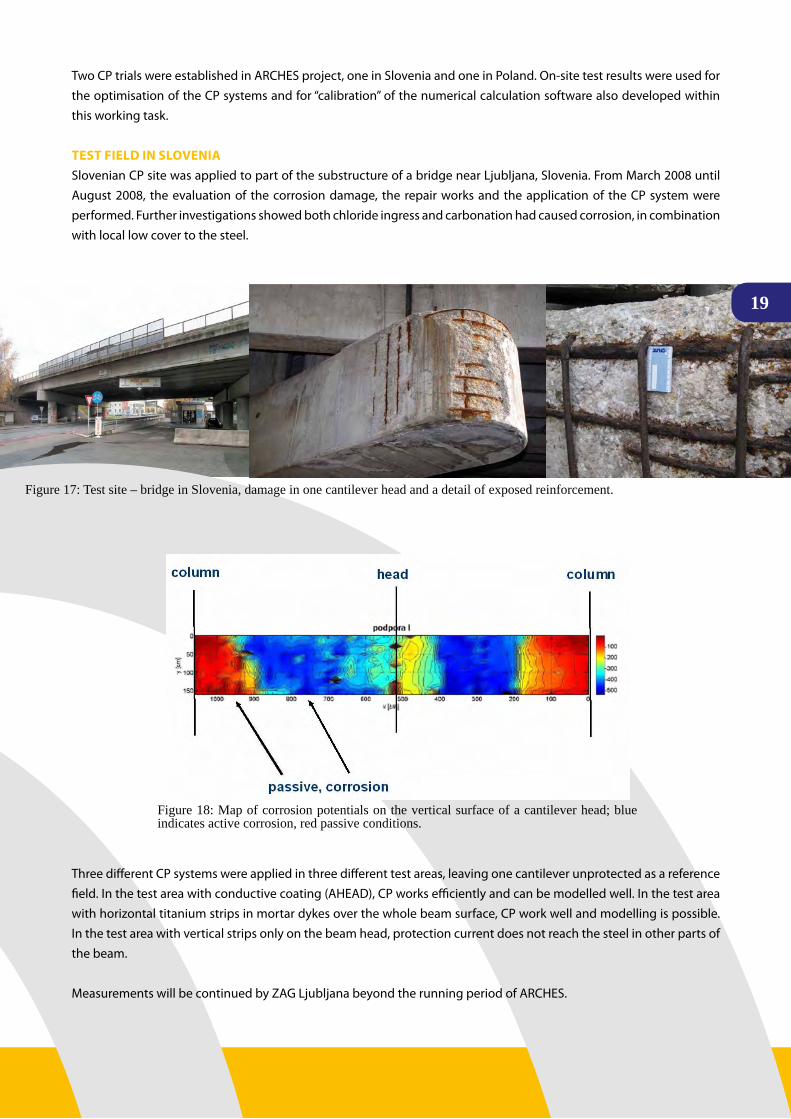
Figure 17: Test site – bridge in Slovenia, damage in one cantilever head and a detail of exposed reinforcement.
Figure 18: Map of corrosion potentials on the vertical surface of a cantilever head; blue indicates active corrosion, red passive conditions.
Two CP trials were established in ARCHES project, one in Slovenia and one in Poland. On-site test results were used for the optimisation of the CP systems and for “calibration” of the numerical calculation software also developed within this working task.
TEST FIELD IN SLOVENIASlovenian CP site was applied to part of the substructure of a bridge near Ljubljana, Slovenia. From March 2008 until August 2008, the evaluation of the corrosion damage, the repair works and the application of the CP system were performed. Further investigations showed both chloride ingress and carbonation had caused corrosion, in combination with local low cover to the steel.
Three different CP systems were applied in three different test areas, leaving one cantilever unprotected as a reference field.Inthetestareawithconductivecoating(AHEAD),CPworksefficientlyandcanbemodelledwell.Inthetestareawith horizontal titanium strips in mortar dykes over the whole beam surface, CP work well and modelling is possible. In the test area with vertical strips only on the beam head, protection current does not reach the steel in other parts of the beam.
Measurements will be continued by ZAG Ljubljana beyond the running period of ARCHES.

Executive Summary Report
20
RCHES
Figure 19: Three different CP systems applied on CP trial application in Slovenia; a) horizontal titanium strips, b) conductive coating, c) vertical titanium strips.
a) b) c)
TEST FIELD IN POLANDThePolishCPtrialwasinstalledonamotorwaybridgeinWarsaw(Poland)inlate2008/early2009.Thecaseinvolvescorrosion damage due to leaking drains (Figure 20a). Preparing for CP trial application, the reinforcement was exposed; a repair mortar was applied and titanium strip anodes were installed (Figure 20b) and subsequently overlaid with mortar. Monitoring of the CP system efficiency will be continued beyond the time of ARCHES project.
NUMERICAL CALCULATIONS FOR CPNumerical modelling of CP has been demonstrated to be a useful tool, both for predicting CP operation in general andthesafetyofpotentialsofprestressingsteelinparticular.FornumericalanalysisofaCPsystem,afiniteelementcomputer model was developed and tested on the basis of the Slovene CP test site results. Numeric analyses was performed for a typical part of the structure to be protected, which ideally includes the (concrete, steel) geometry, polarisation processes at the anode and at the steel and the ohmic drop in the concrete. Using such a model, current densities and potentials can be calculated at every point in the modelled structure. They can be used to verify the spread ofprotectionforvariousanodeconfigurationsandtopredictlocalpolarisationsthatcanbetestedexperimentally.InthescopeofWP3ARCHESprojectanumericalcalculationsforCPtrialinSloveniawasperformed.
Numerical modelling of CP has been demonstrated to be a useful tool, both for predicting CP operation in general and the safety of potentials of prestressing steel in particular.
The full report on the use of smart cathodic protection of steel in concrete can be found in ARCHES Deliverable D12 - “Guideline for Smart Cathodic Protection of Steel in Concrete”.
Figure 20: a) Corrosion damage due to leaking drain system in motorway bridge in Warsaw; b) Titanium strip anodes installed before overlaying on side surface; three strips have already been overlaid in the bottom face.
a) b)

21
DEVELOPMENT / MODIFICATION OF CORROSION MONITORING SySTEM Assessing long-term efficiency of various rehabilitation/corrosion protection techniques requires an advanced corrosionmonitoring system.Variouselectrochemical andphysicalmethodsexist for thedetectionof corrosion inconcrete. All have advantages and disadvantages but none is optimal, and therefore usually a combination of several techniques is required.
WP3ofARCHESprojectfocusedonpreviouslymodifiedversion(SAMARIS)ofclassicalelectricalresistance(ER)probes.Preliminary tests indicated that this type of probe is appropriate for installation into both new and rehabilitated concrete structures. As these probes can be made from various types of steel, the behaviour of different reinforcements (black steel, corrosion resistant steels) can reliably be determined. In addition, these probes can be even polarized, and therefore their implementation in cathodically protected structures is particularly valuable.
Electrical resistance (ER) probes are based on a simple principle of increase in electrical resistance caused by a decrease in the thickness of a metallic conductor. The electrical resistance probes used in the ARCHES project are constructed asaWheatstonebridge,wheretworesistorsareindirectcontactwithconcrete,andtheothertwoareisolated.Thechangeinresistanceismeasuredasthevoltagedifference,whereastheinfluenceofpossibletemperaturechangesismeasuredasthevoltagedropovertheentireWheatstonebridge.
WithintheARCHESprojectanewformandproductionprocessformanufacturingthestainlesssteelERprobeswasdeveloped at ZAG Ljubljana. The stainless steel ER probes were made of the most commonly used type of stainless steel AISI 304 (1.4301), of which the chemical composition and mechanical properties are very similar to those of the re-bars of the same grade of steel.
ER probes were imbedded in concrete specimens and structures for the purpose of ARCHES project testing, including the Slovene CP tests site and the the Krk Bridge (Croatia) low alloyed steel test site.
21
Figure 21: a) Polarisation distribution in conductive coating test area; b) Current distribution in the same test area.
Figure 22: ER probes before concreting in medium size concrete specimens.

Executive Summary Report
22
RCHES
WPMEMBERS:IBDIM: M.ŁAGoDA,T.WIERzBICKI,R.CzACHoWSKI,M.BISKUP;UŻ:P.KoTULA,J.BUJNAK.
ThefinaloutputfromtheresearchteamwererecommendationsfortheprestressedexternallygluedFRPstrips.Therecommendations contained in the guidelines mainly cover the structural strengthening of bridge components of
on-shorestructures,usingprestressedcarbonfibrereinforcedplastics(CFRP).Therecommendationsgiveadviceonthe selection of laminated materials, analysis, design and implementation of strengthening. In some cases it may be advantageous to bond the external FRP reinforcement onto the concrete surface in a prestressed state. Both laboratory andanalyticalresearchshowsthatprestressingrepresentsasignificantcontributiontotheadvancementoftheFRPstrengthening technique, and methods have been developed to prestress the FRP composites under real life conditions.
Prestressing the strips prior to bonding has the following advantages:
• Provides stiffer behaviour as at early stages, as most of the concrete is in compression and therefore contributing at the moment of resistance.
• Crackformationintheshearspanisdelayedandthecrackswhentheyappeararemorefinelydistributedand narrower (crack widths are also a matter of bond properties).
• It closes cracks in structures with pre-existing cracks.• Improves serviceability and durability due to reduced cracking.
WP4 StrengthenIng WIth frP glued StrIPSBy M. Łagoda (IBdIM) – WP 4 Leader
Figure 23: FRP strips prestressing
23
• Improves the shear resistance of members as the whole concrete section will resist the shear, provided that the concrete remains uncracked.
• The same strengthening is achieved with smaller areas of stressed strips compared with unstressed strips.• Withadequateanchorage,prestressingmayincreasetheultimatemomentofresistancebyavoidingfailure
modes associated with peeling-off at cracks and the ends of the strips.• The neutral axis remains at a lower level in the prestressed case than in the unstressed one, resulting in
greater structural efficiency.• Prestressingsignificantlyincreasestheappliedloadatwhichtheinternalsteelbeginstoyieldcomparedto
a non-stressed member.
It should be noted that this technique also has some disadvantages:• It is more expensive than normal strip bonding due to the greater number of operations and equipment
that is required.• The operation takes somewhat longer.• The equipment to push the strip up to the soffit of the beam must remain in place until the adhesive has
hardened sufficiently.
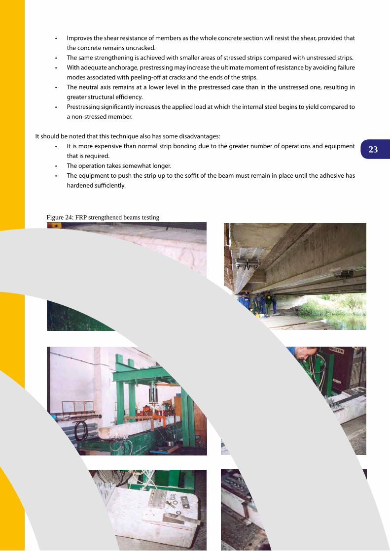
Figure 24: FRP strengthened beams testing

Executive Summary Report
24
RCHES
COMPOSITE UHPFRC-CONCRETE STRUCTURES
The increased volume of European transport urgently requires an effective road and rail system in Central European and
Eastern countries (CEEC) with a major investment in building new and assessing and rehabilitating substandard structures. Ultra-High Performance Fibre Reinforced Concretes (UHPFRC) are characterized by a unique combination of extremely low permeability, high strength and deformation capacity (tensile strain hardening); Extensive R&D works performed during EU project SAMARIS, and five full scale applications realizedsuccessfully in Switzerland since 2004, on bridges and industrial buildings have demonstrated that UHPFRC technology is mature for cast in-situ applications of rehabilitation, using standard equipment, in a fast, efficient and price competitive way. Following the concept originally proposed by Brühwiler (1999), UHPFRC are applied on the bridge superstructure to “harden” zones of severe environmentalandmechanicalloads(exposureclassesxD2,xD3)andonlywhere it isworthusing (Figure25).ThewaterproofingcapabilitiesoftheUHPFRCexemptfromapplyingawaterproofingmembrane. Thus, the bituminous concrete can be applied after only 8 days of moist curing of the UHPFRC instead of theusual3weeksnecessaryfordryingpriortotheapplicationofawaterproofingmembraneonausualmortarorconcrete. The construction process becomes then simpler, quicker, and more robust, with an optimal use of composite construction. The concept is well-suited for bridges and can also be implemented for buildings, galleries, tunnels or retainingwalls.Whenitisrequired,thecombinationoftheprotectivepropertiesanddeformationcapabilityofUHPFRCwith the mechanical performance of reinforcement bars (normal or high grade) provides a simple and efficient way of increasing the stiffness and load-carrying capacity with compact cross sections, Brühwiler et al. (2008)1.
EU Project ARCHES (WP 5) dedicated a major effort to demonstrate the applicability of this innovative rehabilitation technique in NMS and CEEC (Slovenia and Poland), with cheaper and more environmental friendly UHPFRC based on locally available components, and improved rheological properties (tolerance at fresh state to 5 % slope of the substrate).
WP5 ultra hIgh Performance fIbre reInforced concrete (uhPfrc) for rehabIlItatIon of brIdgeS - recent advanceS In nmS and ceecby e. denarIé (mcS-ePfl) – WP 5 leader
WPMEMBERS:ZAG:A.ŠAJNA,J.ŠUPUT,V.BRAS;LCPC: P. ROSSI, G. HABERT; SALONIT ANHOVO: L. REŠČIČ; MCS-EPFL:E.DENARIé,H.SADoUKI,A.SWITEK,E.BRüHWILER; IBDIM: M.ŁAGoDA,T.WIERzBICKI,A.SAKoWSKI
Figure 25 Concept of application of UHPFRC to “harden” bridge superstructures in zones of severe exposure

25
ULTRA HIGH PERFORMANCE FIBRE REINFORCED CONCRETE (UHPFRC) UHPFRC are characterized by an ultra-compact cementitious matrix with an extremely low permeability and by a high tensile strength (above10MPa)anddeformabilitythankstotheadditionofahighdosageofsteelfibres.Therawcomponentsarenotdifferentfromusualconcretes:cement,microsilica,finesand,water,superplasticiser.However,thanks to an optimal choice of components and composition, they have dramatically improved mechanical and protective properties. The very low water/binder ratio of UHPFRC (0.130 to 0.160) makes them extremely dense and impervious to water, gases and aggressive substances such as de-icing salts, to an extend never reached before by concrete technology. In the fresh state, despite their very low water/binder ratio, UHPFRC can be tailored to be self-compacting.
The fractured surfaceof aUHPFRC specimenafter a tensile test showsnumerous steel fibres,pulledout from thematrix,withaveryhighworkoffracture(upto30’000J/m2comparedto200J/m2 for normal concrete).
InthecontextoftheARCHESproject,multilevelfibrousmixesoftheCEMTECmultiscale®, family, with micro and macro steel fibres,originallydevelopedatLCPC,Rossietal.(2005)2, were used. This last generation UHPFRC with up to 9 % vol. steelfibresexhibits tensile strain hardening which is a very important feature needed for cast on site rehabilitation applications in which high eigenstresses are developed at early age under the restraint of the existing substrate. A significantpartoftheworkoffractureofthistypeofUHPFRCisdissipatedinthebulkofthematerial,duringthestrainhardeningphase,intheformoffinelydistributedmicrocracks(Figure26).
The free deformations of UHPFRC at early age are not higher than those of usual concretes. However, contrarily to usual concretes, tensile strain hardening UHPFRC such as CEMTECmultiscale® have a deformation capacity under tension larger than their free shrinkage and thus avoid localized cracking at serviceability (Figure 27).
» Strain hardening UHPFRC turn out to be an excellent compromise of compacity, high tensile strength, and significant deformation capability, perfectly suited for combination with normal concretes, in existing or new structures.
1 Brühwiler E., Denarié E., (2008), “Rehabilitation of concrete structures using Ultra-High Performance Fibre Reinforced Concrete”, Proceedings UHPC-2008, March 05 - 07, 2008, Kassel, Germany.2 Rossi, P., Arca, A., Parant, E. & Fakhri, P., “Bending and compressive behaviours of a new cement composite,” Cement and Concrete Research, 2005, 35, pp. 27 – 33.
25
Figure 26: Fractured surface of UHPFRC with pulled-out steel fibres.
Figure 27: Tensile behaviour of UHPFRC and concrete compared to their free shrinkage deformations.

Executive Summary Report
26
RCHES
Figure 28: Mini-slump cone test on UHPC matrices. Comparison of the final spread of two mixes with b), or without a) cement replacement by mineral addition (limestone filler). a) Pure CEM I 52.2 cement (Salonit), CEM I 52.5 cement (Salonit) blended with addition.
ADVANCES IN CAST-ON SITE UHPFRC TECHNOLOGy Based on extensive research and development works and transfer of technology from EPFL and LCPC to ZAG, Salonit and IBDIM, the following improvements in UHPFRC materials were achieved during the ARCHES project:
• Development of a general methodology for the production of UHPFRC suitable for cast-on site rehabilitation applications, from locally available components.
• Innovative concept of cement replacement by high dosages of limestone filler,without sacrificing theprotective function and mechanical properties.
• Improvement of rheological properties by addition of special thixotropizing admixture, enabling UHPFRC to be applied on slopes up to 5 %.
• Improvement of surfacing techniques.
The achievement of tensile strain hardening, extremely low permeability and self-compacting character are indeed challenges that few current UHPFRC recipes can meet. Starting form the existing UHPFRC mixes developed during the SAMARIS project, new UHPFRC mixes from Slovenian and Polish components had to be developed. To break the workability barrier due to cement/superplasticisers compatibility issues, an innovative concept of Ultra High PerformancematrixwithcementreplacementbylargeamountsoflimestonefillerwasdevelopedatMCS-EPFL.Theunderlying idea is to take advantage of the low degree of hydration (amount of cement grains chemically reacting) of UHPFRCandofthewellknownpositiveeffectoflimestonefillersonworkability.Theperformanceofthisconceptisillustrated by comparative workability measurements using a mini-slump cone (Figure 28).
For the samewater/fines ratioof0.155 (Fines=cement+ limestonefiller), theUHPFRCmatrix recipewithcementreplacementbylimestonefiller(caseB)showsaworkability(finalspreadofthetest)adaptedtotheadditionofthefibrousmixneededtoachieveatensilestrainhardeningresponse(Figure28b).Atthecontrary, incaseA,withthesameSloveniancement (CEMI52.5)andno limestonefiller, thematrix is too stiffand it is impossible toprepareaUHPFRCwiththedesiredfibrousmixandproperties(Figure28a).
This concept was applied successfully to the development of Slovenian and Polish based UHPFRC and provides a general methodology that makes the application of UHPFRC technology feasible with a wide range of cements and superplasticisers in virtually any country (see ARCHES deliverable D06 for more details).
The dramatic reduction of cement content (by a factor of 2) has multiple positive effects among which a very significant reduction of the economical and environmental costs of UHPFRC making them even more attractive for rehabilitation applications.
a) b)

27
OPTIMIZATION OF RHEOLOGy Withrespecttoon-siteapplications,theinnovativepossibilityofadaptingthefreshUHPFRCproperties(thixotropy)tothebasementslopeupto5%isanotherimportantoutcomeoftheARCHESproject.Withtheadditionofathixotropizingadmixture the fresh material characteristics can be tailored for the use on horizontal (self-levelling), vertical or inclined (up to 5 %) surfaces, which remarkably widens the on-site application possibilities. The slope tolerance of the new UHPFRC mixes was validated by especially developed small and medium scale performance tests, Figure 29, 30 as well as large scale trial tests in realistic site conditions of application by a concrete truck, Figure 31, realized at the Salonit plant in October 2008.
Figure 5.2: Pavements in the road simulator: Czech diorite (top) and Slovenian limestone (bottom)
2927
Figure 29: Small scale slope tolerance test.
Figure 30: Medium scale application test on 5% inclined substrate.

Executive Summary Report
28
RCHES
The test was successful and 900 litres of the new ECO-UHPFRC CM32_13, with only 0.3 % thixotropizing addition were applied from a concrete truck on two inclined test surfaces of 10 m2 with 3 and 5 % slopes in the plant. The losses in the truck were extremely small (around 50 litres) and the application time was 10 minutes for 10 m2.
Figure 31: Full scale trial test of application of thixotropized ECO-UHPFRC on 3 and 5 % inclined substrates (Salonit Plant, October 2008)
29
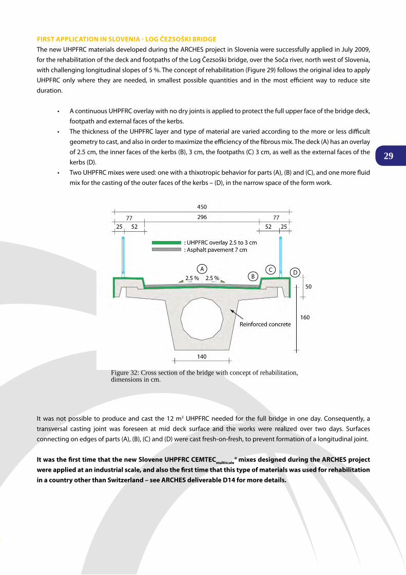
FIRST APPLICATION IN SLOVENIA - LOG ČEZSOŠkI BRIDGEThenewUHPFRCmaterialsdevelopedduringtheARCHESprojectinSloveniaweresuccessfullyappliedinJuly2009,for the rehabilitation of the deck and footpaths of the Log Čezsoški bridge, over the Soča river, north west of Slovenia, with challenging longitudinal slopes of 5 %. The concept of rehabilitation (Figure 29) follows the original idea to apply UHPFRC only where they are needed, in smallest possible quantities and in the most efficient way to reduce site duration.
• A continuous UHPFRC overlay with no dry joints is applied to protect the full upper face of the bridge deck, footpath and external faces of the kerbs.
• The thickness of the UHPFRC layer and type of material are varied according to the more or less difficult geometrytocast,andalsoinordertomaximizetheefficiencyofthefibrousmix.Thedeck(A)hasanoverlayof 2.5 cm, the inner faces of the kerbs (B), 3 cm, the footpaths (C) 3 cm, as well as the external faces of the kerbs (D).
• TwoUHPFRCmixeswereused:onewithathixotropicbehaviorforparts(A),(B)and(C),andonemorefluidmix for the casting of the outer faces of the kerbs – (D), in the narrow space of the form work.
It was not possible to produce and cast the 12 m3 UHPFRC needed for the full bridge in one day. Consequently, a transversal casting joint was foreseen at mid deck surface and the works were realized over two days. Surfaces connecting on edges of parts (A), (B), (C) and (D) were cast fresh-on-fresh, to prevent formation of a longitudinal joint.
It was the first time that the new Slovene UHPFRC CEMTECmultiscale® mixes designed during the ARCHES project were applied at an industrial scale, and also the first time that this type of materials was used for rehabilitation in a country other than Switzerland – see ARCHES deliverable D14 for more details.
Figure 32: Cross section of the bridge with concept of rehabilitation, dimensions in cm.

Executive Summary Report
30
RCHES
siteduration(byafactor3)suchaswiththeuseofUHPFRCalsohelpsdecreasesignificantlytheamountofdetoursfrom users during bridge closure and thus the CO2 footprint of the site.
The intervention was fast (1 month instead of 3 months with traditional technique) and by means of a newly developed surfacing technique it was possible to achieve uniform textured UHPFRC footpath surfaces on which barefoot walking is possible, Figure 33 a). This application demonstrated at an industrial scale the ability of the newly designed UHPFRC mixes to reply to the difficult challenges of the site, without any increase of rehabilitation costs, but to the satisfaction of the owner, user and contractor.
One of the goals of the ARCHES project was to offer sustainable repair and rehabilitation materials and techniques. Therefore the rehabilitation of the Log Čezsoški bridge was analyzed from the point of view of sustainability, based on CO2 balance calculations.The impact due to the production of materials was the major contribution to the environmental impact of the rehabilitation. It was shown, figure 34, thatover the whole life-cycle, the system making use of the new Eco UHPFRC with a large amount of cement replacement by limestone filler has a much lowerimpact than all the other rehabilitation systems, as the durability of UHPFRC is much higher than usual concretes.
Furthermore, at a local level, a dramatically shortened
Figure 33 Processing of the UHPFRC, a) kerbs, b) bridge deck with 5 % longitudinal slope.
a) b)
Figure 34: Global Warming potential induced by the different solutions for the Log Čezsoški rehabilitation, over the life cycle (100 % = traditional rehabilitation system with standard concrete).
Figure 35: The Log Čezsoški bridge after the rehabilitation.
31ProJect reSultS
The ARCHES team is very proud to present the Final Report of the “Assessment and Rehabilitation of Central European Highway Structures” (ARCHES) Project. This Report was prepared with the common effort of the members from
the Project Consortium. It presents the major activities undertaken during the three years of activity, paying special attention to the Projects goals and the results thereof.
ThefinalgoalisnowtobringtheARCHESresearchresultsintocommonpractice,enablingitsuseinbridgestructuremaintenance, within Central Europe. The Deliverables have been prepared as recommendations, which can be used by road authorities, highway engineers and researchers for better bridge assessment and rehabilitation.
Whiletheprojecthasformallyended,theresearchactivityhasnot.StudyonseveraloftheARCHESexperimentsareon-going and will continue beyond the close of the project. To follow the outcomes of this activity, we advise you to visit the Arches website http://arches.fehrl.org/,whereyoucanfindthefulltextofRecommendationspreparedwithintheProject,aswellasthefindingsoftheon-goingresearchdevelopments.
Supplementary information can be found at the Forum on European National Highway Research Laboratories (http://www.fehrl.org/), including information on new projects and project possibilities within the transport area.
Mr. Tomasz Wierzbicki Project Coordinator
© Matjaž Zupanc (ZAG)
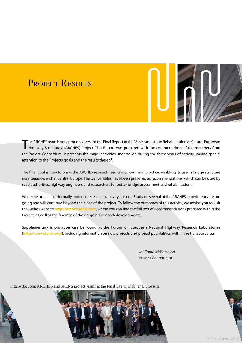
Figure 36: Joint ARCHES and SPENS project teams at the Final Event, Ljubljana, Slovenia