pocket guide for firestopping inspection manual
DESCRIPTION
Pocket Guide for Firestopping Inspection ManualTRANSCRIPT

FirestoppingInspectionManual
••••• FFFFFor Thror Thror Thror Thror Throughoughoughoughough P P P P Penetrenetrenetrenetrenetrations.ations.ations.ations.ations.
FirFirFirFirFire Resistive Resistive Resistive Resistive Resistive Joints,e Joints,e Joints,e Joints,e Joints,PPPPPerimetererimetererimetererimetererimeterFirFirFirFirFire Barrier e Barrier e Barrier e Barrier e Barrier SySySySySystems and Firstems and Firstems and Firstems and Firstems and FireeeeeRated DuctRated DuctRated DuctRated DuctRated DuctEnclosurEnclosurEnclosurEnclosurEnclosuresSyesSyesSyesSyesSystems.stems.stems.stems.stems.
Third Edition
www.firestop.org
A PocketGuide ForInspectors

Contents
Scope …………………………........……..… 3
Fire Test Standards ……………....…..… 4
Testing Laboratories ………....……….... 5
Building Code Requirements ……..…. 6
Products Overview ………………..….. 7
Inspection Process …………….....…… 8
Firestopping and the Codes ………… 14
Inspection Guidelines for Through
Penetration Firestop Systems ........ … 15
Inspection Guidelines for Fire
Resistive Joints Systems ………......... 17
Inspection Guidelines for Perimeter
Fire Barrier Systems (Curtain Walls) .... 20
Inspection Guidelines for
Fire Rated Duct Enclosures …….….…. 25
Engineering Judgments ……….....……. 28
Glossary ………………………...........…… 29
UL System Approach ……………….. 32
Seismic Considerations ……………... 35
Systems Listing Table ………………. 36
Scope
The following pocket manual is designed as a reference tool forgovernmental inspectors, third-party inspectors and otherpersonnel with a need for a simplified, yet thorough approachto the firestopping inspection process. This pocket manual isintended as a tool and not as an all-encompassing source book.This booklet is separated into two parts. The first section is intendedto provide guidelines for a successful inspection process. The secondsection of the booklet will go more in depth on the guidelines forspecific firestopping systems in categories of ThroughPenetrations, Fire Resistive Joints, Perimeter Fire BarrierSystems (Curtain Walls) and Flexible Rated Duct Enclosures.Key words are listed in the glossary for clarification purposes.
The term Firestopping, in this manual, will refer to: (1) thesealing of holes and gaps within a rated assembly, commonlyreferred to as Through-Penetration Firestops, (2) the sealingof linear gaps between rated assemblies, referred to as Fire-Resistive Joint Systems and (3) the sealing of the linear gapbetween or along rated floors and rated or non-rated curtainwalls, referred to as Perimeter Fire Barrier Systems. The termFire Rated Duct Enclosure will refer to protective systems usedto enclose duct systems penetrating a rated assembly.
The Firestopping Systems are tested to specific test standards.Through-Penetration Firestops are tested to ASTM E814 or UL1479, Fire-Resistive Joint Systems to ASTM E1966 or UL 2079and Perimeter Fire Barrier Systems to ASTM E2307.
Firestopping Systems must be tested to the above criteria bycertified independent third party testing agencies. The TestingAgencies usually publish the results in proprietary directories,which are readily available. Some of the more common and wellknown testing and approval agencies are UnderwritersLaboratories, Intertek Testing Services, Factory Mutual andSouthwest Research Institute.
Fire Resistive Duct Enclosure Systems, are tested alternativesto fire resistive shaft enclosures which function to contain firesthat occur inside the duct, prevent fire spread into the ductworkfrom an external fire and allow for zero, or reduced clearance tocombustible construction. A tested through penetration firestopsystem is required when the duct enclosure system penetratesa rated floor or wall assembly. 3
Sco
pe
3

INSPECTION GUIDELINES
ForFirestoppingSystems
Applicable Standards
The Test Standards relevant to Firestop Systems are:
1. ASTM E 814 (ANSI/UL 1479) “Standard Test Methodfor Fire Tests of Through-Penetration Fire Stops”
2. ASTM E 1966 (ANSI/UL 2079) “Standards TestMethod for Fire-Resistive Joint Systems”
3. ASTM E 1399 “Cyclic Movement and Measuring theMinimum and Maximum Joint Widths of ArchitecturalJoint Systems”
4. ASTM E 2174 “Standard Practice for On-SiteInspection of Installed Fire Stops”
5. ASTM E 2307 “Standard Test Method for Determiningthe Fire Resistance of Perimeter Fire Barrier SystemsUsing the Intermediate Scale, Multi-Story TestApparatus”
6. ASTM E 2393 “Standard Practice for On-SiteInspection of Installed Fire Resistive Joint Systemand Perimeter Fire Barriers”
7. ASTM E 2336 “Standard Test Methods for FireResistive Grease Duct Enclosure Systems”
8. ISO 6944 “Fire Resistance Tests – Ventilation Ducts”9. ICC ES AC179 “Acceptance Criteria for Metallic
HVAC Duct Enclosure Assemblies”
The fire testing of penetration firestop and perimeter barriersystems require a demonstration that the system is able to stopthe passage of flame (F Rating) and withstand a hose streamtest. Fire tests also include provisions for measuring the T Ratingand the L Rating. The fire testing of fire resistive joint systemsrequire a demonstration of the ability to stop the passage of
4
INSP
EC
TIO
NG
UID
EL
INE
SF
or
Fir
esto
pp
ing
Sys
tem
s

both flame and thermal transmission (assembly rating). Firetests of firestop systems are conducted using positive furnacepressures.
For dynamic joint systems, a specific number of expansionand contraction cycles precede the fire test in order to measurethe movement capabilities of the joint systems. The movementcapability of a joint is expressed as a % of the installed (nominal)width of the joint system.
The fire resistance rating of the firestop system must equalthe fire resistance rating of the penetrated fire separatingassembly or floor assembly in which the firestop system isinstalled. With a few exceptions, the methods and materials usedin the penetrations, joints and duct enclosures are tested as asystem to demonstrate the methods and materials function asfire containment for the required fire resistance rating. Amodification to a tested system voids the rating of the system.
Testing Laboratories
There are several independent testing laboratories, alsoreferred to as third party testing agencies, which conduct thefire testing of firestop and duct enclosure systems. The fire testresults are usually included as design listings in the fireresistance directories published by the testing laboratory. TheseDirectories are an important source of information during theplan review process and inspection process. The details, systemnumbers, manufacturer installation recommendations, and otherdesign listing information are often referred to on the plansubmittals. A thorough knowledge of the design listinginformation is critical to the inspections of firestops and ductenclosures.
The following are some of the recognized independentlaboratories conducting tests of firestop systems:
1. Underwriters Laboratories Inc., Northbrook, IL(847) 272-8800 www.ul.com
2. Southwest Research Institute, San Antonio, TX(210) 522-2311 www.swri.com 5

3. Factory Mutual, Norwood, MA (781) 762-4300 www.fmglobal.com4. Intertek Testing Services, Antioch, CA
(925) 756-6606 www.intertek.com
Check Points:· Do your building and fire department plans examiners and
inspectors routinely use Testing Laboratories Directories?These directories can be ordered directly from the testinglaboratories.
· Are you unsure of the compliance of a specific firestopassembly with the listed design? Check out the latestdesign listings on the Laborator ies websites, e.g.www.ul.com/database, www.swi.com, www.fm.com,www.intertek.com
Building Code Requirements
The Building Codes have very clear requirements on passivefire protection. Fire investigative reports have consistently shownthat unprotected or improperly protected penetrations and jointscause millions of dollars in property damage and contributed tothe loss of life and injuries due to the uncontrolled migration offire, smoke and toxic gases. In order to promote life safety andproperty protection, the national building codes include firetesting and performance requirements for penetration firestopand fire resistive joint systems and rated duct enclosures. Theseprovisions are included in Chapter 7 – Fire Resistance RatedConstruction of the current model codes, which are:
· ICC’s International Building Code (IBC)· NFPA 5000
Whenever required by Code, the fire resistance ratings of floors,walls, floor/ceiling, roof/ceiling assemblies or rated ductenclosures must be restored when an opening is made toaccommodate penetrations for mechanical, electrical, plumbing,communication systems and ventilation ducts. Joints betweenfloors, walls, floors and walls, etc, must have the same fireresistance ratings as the adjacent construction.6

NFPA 101, Life Safety Code, NFPA 70, National Electric Code,and IAPMO’s Uniform Plumbing Code (UPC), also includeprovisions related to protection of penetrations. The IBC andNFPA 5000 have explicit requirements for inspection of firestopsystems before they are concealed. The IBC requires thatevidence be submitted to the local official showing that thematerials and methods of construction used to protectpenetrations, joints and ventilation ducts in fire resistance ratedbuilding elements shall not reduce the required fire resistancerating. The International Fire Code has requirements for periodicinspection of firestop systems throughout the life of the building.
Check Point:Have you checked your local code requirements? The IBC,
NFPA 5000 and the Life Safety Code, NFPA 101, include differentrequirements for firestop systems to meet certain performanceand testing criteria specific to various construction assemblies.Check out the IFC website www.firestop.org for latest updateson firestop systems regulations.
Products Overview
There are four categories of Firestop materials:
- Fill, Void or Cavity Materials:o Intumescent Sealants/Caulks;o Silicone Sealants/Caulks;o Acrylic Sealants/Caulks;o Urethane Sealants/Caulks;o Ceramic Sealants/Caulks;o Moldable putties;o Pillows/Bags;o Sheets/Boards/Blocks;o Mortars;o Intumescent Wrap Strips;o Silicone Foams;o Coatings/Sprays.- Factory and Field Assembled Devices:o Sleeves/Collars;o Mechanical Joint Systems. 7

- Forming/Backing Materials:o Mineral Wool Batts;o Ceramic Fiber Blankets/Boards;o Non-Ceramic Insulation Blankets;o Foam Packing/Backer Rod.
- Duct and Pipe Covering Materials
Inspection Process
The following is a recommended inspection process based oninterviews across the country with building departments’inspectors who have successfully implemented such a program.These jurisdictions require that the protection of penetrations,joints and ventilation ducts not be concealed from view untilinspected and approved. Similar requirements are found in theIBC (Section 109.3.6, 2006 Edition). Some building departmentscollaborate with the fire department to conduct the firestopsystems inspections.
ASTM published ASTM E 2174 “Standard Practice for On-SiteInspection of Installed Fire Stops” and ASTM E 2393 “StandardPractice for On-Site Inspection Fire Resistive Joint System andPerimeter Fire Barriers”. These standards shall be referencedwhen third party inspections are conducted for penetrationfirestop, fire resistive joint and perimeter barrier systems.
Part I – Inspection Process: Plans Examination/Review
The local authority having jurisdiction (AHJ) must approveFirestop system details and Firestop products and Rated DuctedEnclosures. Hence, Firestop systems details and materialsshould be included on the plans and specifications.Manufacturer’s cut sheets are often accepted if they aregenerated by an approved testing agency. If details, productsand specifications are not sufficient to provide clear directionsto the general contractor and firestop installer, the submittalsshould be noted as incomplete and returned to the designer tobe resubmitted with the required information. When the plans8

and specifications are clear and complete, most field problemswith firestop systems can be avoided.
Check Points:- Do the specifications include what test method the
materials or firestop systems shall be tested to?- Which sections of the architectural plans contain the
firestop systems details?- Are the specific firestop system and rated duct enclosures
details included on the plans?- Has the local authority having jurisdiction (AHJ) approved
the products used in these systems?- Are the firestop products appropriate for the field
conditions? Refer to the design listings and manufacturerdata sheets.
- Are the specified fire resistive joints tested for the amountof movement and type of movement required?
- Is the firestop system or duct system listed? (e.g. byUnderwriters Laboratories (UL), Factory Mutual (FM),Intertek Testing Services (its).
- Do the specific firestop systems comply with the standardtesting requirements for the in-place conditions?
Part II – Inspection Process: Engineering Judgments
It is not unusual to find, in construction projects, uncommondesigns or unique conditions that require special consideration.The protection of these conditions will necessitate EngineeringJudgments (EJ’s) since they have not been tested and do notcomply with a published design listing. The International FirestopCouncil has published “Recommended IFC Guidelines forEvaluating Firestop Systems Engineering Guidelines” to assistdesigners, plan reviewers and inspectors in addressingnonconforming construction details. Tested systems shouldalways be specified unless EJ’s are the only option. EngineeringJudgments should be developed using sound engineeringpractices to ensure that life safety is not compromised. The plansubmittals should always indicate which system details are 9

based on EJ’s and the pre-approved details must be madeavailable for the field inspector.
The IFC guidelines can be obtained from the IFC website:www.firestop.org.
Part III – Inspection Process: Pre- Construction/Pre-Planning Meeting
The perfect oppor tunity to initiate discussion on thecoordination of work among the trades, the general contractorand building inspector is during the pre-construction meeting.This discussion is important since the application of firestopprotection systems is affected by the work of many tradesincluding mechanical, plumbing, electrical, walls and ceilings,fire protection, etc.
An early discussion of who is going to be responsible forrestoration of the fire resistance ratings will eliminate aggravationand expense later in the construction. If there is no cleardelegation of responsibility for the installation of firestop systemsfor the penetrations, joints and ventilation ducts, it is vital thatthe general contractor understand that it is his responsibility toensure the fire resistance ratings of the structure.
The pre-construction meeting should also be used to:- Agree on all the penetrations, joints and ducts to be
protected in accordance with the approved constructionplans;
- Schedule the trade’s work in conjunction with the firestopinstallation work;
- Schedule the firestop inspections and coordinate with thefirestop contractor work;
- Agree on whether the building or fire inspector will beconducting the inspections.
Check Points:- Do the general contractor and subcontractors understand
that the protection of penetrations, joints and ducts will beinspected?10

- Who is going to be responsible for the protection of allpenetrations, joints and ducts?
- Who is going to conduct the inspections and when?- What are the qualifications/experience of the firestop
installer indicating expertise in that field?
Part IV – Inspection Process: Conduct of Inspection
The ability of penetration firestop systems, fire resistive jointand ventilation systems to perform their intended function offire containment is directly related to the quality of theirinstallations. Thorough inspection is an integral component ofany passive fire protection quality control program.
It is usually feasible to visually inspect each penetration andthe entire length of every joint and ventilation duct. How manyinspections are enough? This is a judgment call by the inspector.
Example: It would be reasonable if there were 20 or 30penetrations, to observe 2 or 3 representative installations. 2 or3 representative installations out of hundreds, or thousands, ofpenetrations would not provide reasonable ver ification,particularly if different subcontractors were involved in theirinstallations.
Major elements of quality firestop inspections are:- Firestop systems must not be concealed from view before
being inspected and approved;- Walk through visual inspections should be made during
the firestop installation;- When necessary or required, destructive evaluation will
be made on various types of firestop systems;- Flashlights, coring device and other appropriate tools make
a proper inspection easier;- Proper depths, annular space, proper attachments and
spacing and product types are critical to the effectivenessof the system;
- Construction documents detailing the firestop locations andsystems must be kept on site to assist in the conduct ofthe inspection; 11
- Observe that empty containers, wrappings or boxes of thespecified materials are in sufficient quantity to have beeninstalled correctly;
- Observe that the actual products, containers, wrappingsor boxes are labeled with the approved testing agencymarks and are as specified in the submitted details;
- Measure the depth and width of materials as indicated inthe details (sometimes density measurements are alsorequired for products such as thermal insulation);
- Observe that joints have been installed in such mannerthat the required movement can be achieved (temporaryscrews used to hold studs to ceiling runners must beremoved);
- Compare the installed firestop system with the approvedsubmitted details;
- Observe a reasonable degree of workmanship, whichwould indicate compliance with the specified designs;
- Deficient installations must immediately be corrected andthen re-inspected before concealment.
Check Points:- Are random and timely inspections conducted to make sure
that corrections can be made before the completion offirestop installations?
- Is the building or fire inspector familiar with the coderequirement for penetration firestop systems, fire resistivejoint and ventilation duct systems?
- How many destructive inspections will be conducted?- What is your building inspection policy and procedure for
making firestop inspections?- Is the inspection report for all firestop systems included in
the final inspection report?
12

TheInspectionProcess
The time allocated for inspections can be drasticallyreduced if the proper paperwork is present in advance ofthe f ie ld inspect ion. P lanning and communicat ionbetween the building designer and the installer prior toconstruct ion wi l l save t ime, costs and resources inassu r i ng t he app l i ca t i on o f t he p rope r sys tems.Verification of system testing and listings with a nationallyrecognized laboratory, prior to installation in the field, iskey to a smooth inspection process. The costs and timeassociated with removing improperly applied materialscan be drastical ly reduced if the respective throughpenetration firestop systems, fire resistive joint systemsand f lex ible rated duct enclosure documentat ion isconfirmed prior to installation. Use of applicable ASTMpractices will provide guidelines for inspection of installedsystems.
13

FirestoppingAnd TheCodes
Penetrations and Joints Firestopping is a form of passive fireprotection that is required in all penetrated rated assembliesand the joints between them. The International Code Councilspecifies firestopping within Chapter 7 of their InternationalBuilding Code. The National Fire Protection Association alsospecifies firestopping requirements in its Life Safety Code, NFPA101, National Electric Code publications and in its NFPA 5000Building Code.
Fire Resistive Duct Enclosures for grease and HVAC ducts aretested protection systems which provide 1 and/or 2 hour fireratings. The systems are utilized as an alternative to fire resistiverated shaft construction and also permit zero, or reduced,clearance to combustible materials. The International CodeCouncil specifies fire resistive duct enclosures in Chapter 5 oftheir International Mechanical Code (IMC). Requirements arealso contained in NFPA 96, and IAPMO (UMC). A duct enclosuresystem penetrating a rated assembly should also be properlyfirestopped.
14
INSPECTION GUIDELINES
INSP
EC
TIO
NG
UID
EL
INE
SF
ires
top
pin
g A
nd
Th
e C
od
es

INSP
EC
TIO
NG
UID
EL
INE
S
INSPECTION GUIDELINES
For ThroughPenetrationFirestop Systems
Step One:
Verify the documents and submitted drawings referenceapplicable through penetration assemblies containingsealants, devices and/or other materials tested to ASTM E814or UL 1479 by accredited testing agencies. These systemsshould be published and readily available via the internet orother means. Such listings are found in section XHEZ withinVolume 2 of Underwriters Laboratories Inc. Fire ResistanceDirectory or Warnock-Hersey and OPL Mark ProductDirectory.
Reason: There are many different types andcombinations of through penetrations, coatings,sealants and devices that have not been proven to
maintain or restore the rating of the assembly through testing toASTM E814 or UL 1479.
Step Two:
Verify that the Through-Penetration System being used has beentested to the hourly rating necessary ie. 1 hr., 2 hr., etc., andwith the type of assembly being penetrated.
Reason: The building codes require that the ratingof a firestop system shall not be less than the fireresistive rating of the penetrated assembly. Concrete,
gypsum and wood assemblies all behave differently in a fire. 15
Fo
r T
hro
ug
h P
enet
rati
on
Fir
esto
p S
yste
ms
INSP
EC
TIO
NG
UID
EL
INE
S

Step Three:
As an overview of these steps, verify the parameters indicatedin the system are the same as those installed in the field:(Download checklist form from the IFC web sitewww.firestop.org).
A. Is the through penetration system rated for the type and natureof assembly (thickness of concrete, stud width, etc.)?
B. Is the rating of the through penetration system equal orgreater than the assembly penetrated?
C. Do the supplied products have labels from a recognizedquality assurance agency?
D. Does the field installation follow the listing?a. For the size of opening prior to firestopping?b. Nature and quantity of penetrant(s), (material, size,
diameter, insulation type & thickness, etc.)?c. Annular space requirements, (minimum, maximum,
nominal, etc.)?d. Specified forming, packing or backing material, (when
required)?e. Specified sealant, coating, device or firestopping
product indicated, (type, amount, depth, location, etc.)?f. Specified accessory items, (anchors, fasteners,
securing devices, plates, etc.)?
Reason: Deviations from a listed and labeled designwill likely result in a failure of the installed system.Consult manufacturer for validation.
16

INSPECTION GUIDELINES
For Fire ResistiveJoints Systems:IncludingMechanical FireBarrier System
Step One:
Verify the documents and submitted drawings referencelegitimate, fire resistive joint systems tested to ASTM E1966 orUL 2079 by accredited testing laboratories or certified third partytesting agencies. These systems should be published or readilyavailable via the internet or other means. Such listings can befound in section XHBN within Volume 2 of Underwriters LaboratoriesInc. Fire Resistance Directory or Omega Point LaboratoriesDirectory of Listed Building Products, Materials & Assemblies.
Reason: Many coatings, sealants and configurationof materials have never been tested in joint systemsand should not be applied to such applications.
Step Two:
Verify the documents and submitted drawings reference whetherthe joint is static (not subject to movement) or dynamic, (subjectto movement). Virtually all joints are intended to be dynamic.
Reason: A static joint design, (e.g. FF-S, HW-S, FW-S) should not be applied to a dynamic joint condition.A dynamic joint design, (e.g. FF-D, HW-D, FW-D),however, may be applied to a static condition. 17
INSP
EC
TIO
NG
UID
EL
INE
SF
or
Fir
e R
esis
tive
Jo
ints
Sys
tem
s:In
clu
din
g M
ech
anic
al F
ire
Bar
rier
Sys
tem

Step Three:
If the joint is dynamic, as in most cases, verify the documentsand submitted drawings reference systems that have been testedfor the required amount of movement. A system listing a nominal1 inch joint width with 25% compression or extension, actuallyallows for a movement of ¼” of compression and ¼” of extension.
Reason: Building code language requires that jointsystems be capable of handling “expected” buildingmovement. Joint systems not tested for the required
movement will likely fail after installation.
Step Four:
If the joint is dynamic, verify the documents and submitteddrawings reference joint systems that have been tested for theclass/type of movement.
Class I - Thermal (500 cycles at 1 CPM)Class II - Wind Sway (500 cycles at 10 CPM)Class III - Seismic (100 cycles at 30 CPM)Combined – (100 at 30 CPM & 400 at 10 CPM)
Reason: The installed joint shall be cycle tested forthe appropriate application.
Step Five:
Verify the rating of the joint system is greater than or equal tothe rating of the assemblies it is connecting.
Reason: The building codes require that the ratingof a joint system shall not be less than the fireresistive ratings of the adjacent assemblies. 18

Step Six:
As an overview of these steps, verify the parameters indicatedin the system are the same as those installed in the field:(Download checklist form from the IFC web site www.firestop.org)
A. Is the joint system tested and listed?B. Is the joint static or dynamic?C. If dynamic, is the joint system tested for the amount
of movement required?D. Is the joint system tested for the class & type of
movement required?E. Is the rating of the joint equal to or greater than the
assemblies it is adjacent to?F. If a mechanical system, are the specified tracks
installed in the installation?G. Do the supplied products have labels from a
recognized quality assurance agency?H. Does the field installation follow the listing?
a. Specified forming, packing or backing material?b. Specified type of sealant, coating or device?c. Specified amount, depth, location of sealant,
coating or device?d. Specified accessory items – cover plates, bond
breaker tape, and specified deflection track?
Reason: Deviations from a listed and labeled designwill likely result in a failure of the installed system.Consult with manufacturer for validation.
19

INSPECTION GUIDELINES
ForPerimeter FireBarrier Systems(Curtain Walls)
Step One:
Verify documents and submitted drawings reference legitimatePer imeter Fire Barr ier Systems such as UnderwriterLaboratories, Inc. CW-S or CW-D or Intertek Testing ServicesCEJ designations.
Reason: Documents referencing only fire resistivejoint systems such as FF, FW, or HW should not beaccepted for curtain wall applications. The behaviorand testing of a curtain wall in a fire is significantly
different from standard joint tests.
Step Two:
Verify the rating of the system is greater than or equal to therating of the floor.
Reason: The continuity requirements within thebuilding codes state that the rating of a floorassembly must extend to and be tight against an
exter ior wal l .
INSP
EC
TIO
NG
UID
EL
INE
S
20
Fo
r P
erim
eter
Fir
e B
arri
er S
yste
ms
( C
urt
ain
Wal
ls)

Step Three:
Verify firestop material to be used is classified and listed for usein Perimeter Fire Barrier Systems. Such listings can be foundin Section XHDG within Volume 2 of Underwriters LaboratoriesInc. Fire Resistance Directory or Omega Point LaboratoriesDirectory.
Reason: Many materials, coatings and sealants havenever been tested in perimeter fire containmentsystems and should not be substituted in listed andlabeled systems.
Step Four:
Verify documents reference systems that have been tested withwindows or vision glass if the building has glazing close to thesafing area.
Reason: Some systems were tested withglazing within 6" of the safing area while othersystems were for structures with limited glazing such
as storage and warehouse facilities.
Step Five:
Verify a stiff steel reinforcement member, if required, has beenplaced behind exposed curtain wall panel insulation. Typicalstiffening members can be steel hat channels, “L” or “T” angles.
Reason: A stiffener is needed to maintain thecompression fit of the safing insulation. Without it,the safing insulation may fail to perform as tested. 21

Step Six:
Verify insulation type and brand used is listed within the testedsystem. Mineral wool is the typical insulation of choice.
Reason: Fiberglass insulation melts at 1050 F, wellbelow the 2000 F temperature range of a typicalf i r e .
Step Seven:
If required by the tested system, verify insulation panels aresecurely fastened with mechanical fasteners per the system,instead of just friction-fitted in place.
Reason: The lower transoms and mullionsmay degrade and melt during a fire situation causingthe curtain wall insulation to fall out prematurely if it
is not fastened correctly.
Step Eight:
Verify that exposed mullions, if required by the system, arecovered with the proper insulating barrier securely fastened withmechanical fasteners per the system design.
Reason: Exposed mullions may degrade prematurelyin a fire.
Step Nine:
Verify safing clips or “Z” clips have been used if the systemrequires it.
Reason: Some systems allow for the safinginsulation to be friction fitted in place, others requireclips to support the safing insulation. 22

Step Ten:
Verify coating or sealant has been applied to the proper depth.A common inspection practice is to be on site just prior to theaddition of the sealant to verify the correct application thicknessis being followed. The inspector may request samples from theinstalling contractor after which the installing contractor shallmake the necessary repairs to the destructively sampled area.A scale or caliper is sufficient for measuring the sealant depth.
Reason: Minimum sealant depths are required bythe system designs to assure the rating is met andto prevent smoke, fumes or hot gases from seepinginto the non-fire area.
Step Eleven:
As an overview of the above steps, verify the parametersindicated in the system are the same as those installed in thefield: (Download checklist form from the IFC web site)
A. Is the perimeter fire barrier system tested for the typeand nature of assembly, (minimum thickness of concrete,transom spacing, etc.)?
B. Is the rating of the perimeter fire barrier system equal orgreater than the floor assembly?
C. Do the supplied products have labels from a recognizedquality assurance agency?
D. Does the field installation follow the listing?a. Width of gap between floor edge and curtain wall at
time of installation.b. Design detail includes vision glass if applicable.c. Specified curtain wall spandrel insulation, (type,
thickness, density, etc.).d. Specified spandrel panel perimeter angles, (gauge
thickness, dimensions, fastener spacing). 23

e. Specified framing and/or mullion covering, (type,thickness, density, etc).
f. Support clips for safing insulation, if specified.g. Specified forming or safing insulation, (type, %
compression, depth, etc).h. Specified sealant, coating, device or firestopping
product, (type, depth, location, etc).
Reason: Deviations from tested, l isted &labeled design will likely result in a failure of theinstalled system. Consult with manufacturer for
validation.
24

INSPECTION GUIDELINES
For Fire RatedDuct EnclosureSystems
Step One:
Verify the documents and submitted drawings referencelegitimate fire resistive duct enclosure systems tested byaccredited testing laboratories or certified third party testingagencies. These systems and insulation components should belisted, labeled, published and readily available via the internetor other means. Listings can be located in Intertek TestingServices (formerly Omega Point Laboratories) Directory of ListedBuilding Products, Materials & Assemblies and in theUnderwriters Laboratories Inc. Fire Resistance Directory.
Reason: There are generic insulating materials thathave not been tested as a fire resistive duct enclosuresystem to verify their performance when installed in
a duct configuration under fire conditions. Generic insulatingmaterials do not meet code requirements and should not beused for this application.
Step Two:
Verify the duct enclosure system is tested to the appropriateStandard for the specific type of duct system. Grease duct enclosuresystems are tested per ASTM E2336, which includes a full scaleASTM E 119 engulfment test. HVAC duct enclosure systems aretested per ISO 6944, Type A for closed duct systems and Type B forduct systems that contain openings. Additional evaluation ofventilation duct enclosure systems for compliance to thepertinent Mechanical Code can be conducted per AC 179. AnASTM Standard for Fire Resistive Ventilation Duct EnclosureSystems is under development, but not published at this time.
INSP
EC
TIO
NG
UID
EL
INE
SF
or
Fir
e R
ated
Du
ct E
ncl
osu
re S
yste
ms
25

Reason: Various type duct systems present differentfire threats. Duct enclosure systems need to be testedusing the appropriate Standard to ensure the fire
exposure and performance criteria are representative ofconditions expected for that type duct system when installed inthe field.
Step Three:
Verify the fire resistance rating of the duct enclosure systemand corresponding firestop system are equal or greater thanthe required fire resistive rating for the building constructionassembly penetrated.
Reason: The mechanical code requires the fireresistance rating of the duct enclosure system be atleast equivalent to the surrounding building
construction. The F and T ratings for the corresponding ductfirestop system must also be at least equivalent to the ductenclosure system and the surrounding assembly.
Step Four:
Verify the parameters indicated in the system are the same asthose installed in the field:
A. Duct System Type – kitchen grease exhaust,hazardous material exhaust, ventilation, supply/return, etc;
B. Duct Construction – dimensions, material, gauge,reinforcement, connections, vertical or horizontalorientation;
C. Enclosure System – labeled components, number oflayers, fire rating, required clearance to combustibles,thickness and density of material, material joints (overlapof material, taping of cut edges or seams), etc; 26
D. Enclosure System Attachment – mechanical methodof attachment to duct (typically steel banding and/orcapacitor discharge insulation pins), components,spacing, gauge, etc;
E. Duct Suppor ts – hanger system components,frequency of location, clearance to enclosure system,protection requirements;
F. Access Door – field fabricated or pre-fabricated doorconstruction and protection with enclosure systemmaterial must match design listing;
G. Firestop System – refer to design listing for fire ratedassembly construction, annular space, packingmaterial type and depth, and firestop material typeand depth.
Reason: Deviations from a tested, listed and labeleddesign nullifies compliance and could result in afailure of the installed system. Consult with
manufacturer for validation of any aspects that do notmatch the specified design.
27

Engineering Judgments
Although there are many listed systems, thereare some firestopping configurations that falloutside the envelope of tested designs. It isimpossible to anticipate every field condition andthese situations should certainly not be ignoredby the firestop industry. Testing agencies and
manufacturers, usually handle these unusual occurrences withthe issuance of an Engineering Judgment. An EngineeringJudgment is not a substitute for a tested system, and anavailable tested system should always take precedent overa judgment. An Engineering Judgment is a solution based onthe interpolation of data done by a testing agency’s qualifiedtechnical personnel, a manufacturer, or by a knowledgeableregistered Professional Engineer or Fire Protection Engineer.The issuer of an Engineering Judgment shall be responsible foranswering any questions pertaining to data, source or limits ofthe judgment.
Judgments should be developed by following sound practice toensure that life safety issues are not compromised. A usefulpublication for evaluating engineering judgments calledRecommended IFC Guidelines For Evaluating Firestop SystemsEngineering Judgments (EJ’s) is available from the InternationalFirestop Council.
28

Document Glossary
Annular - The region between penetrants or betweenSpace penetrants and the periphery of the opening.
Also referred to as the annulus.
Curtain - Either a rated or non-rated, non-load bearingWall exterior wall assembly secured and supported
by the structural members of the building.
CPM - Cycles per minute.
Engineering - An engineering evaluation of non- typicalJudgment conditions which do not conform to existing
tested systems. The evaluation may be in theform of a letter or drawing.
Fireblocking - Building material installed to resist the freepassage of flame and gases to other areas ofthe building through concealed spaces.
Firestopping - The sealing or materials used to seal gaps,holes, or voids within or between assembliesto regain the initial rating of the breachedassemblies.
F Rating - The amount of time that a firestop systemremains in tact and does not permit the spreadof fire and hot gases when tested in accordancewith ASTM or UL test standards for specifiedsystems.
Fire Resistive - A tested protection system for enclosing ductDuct Enclosure systems that penetrate a fire rated assembly.
Typically used as an alternative to fire resistiveshaft enclosures. 29
Glo
ssar
y
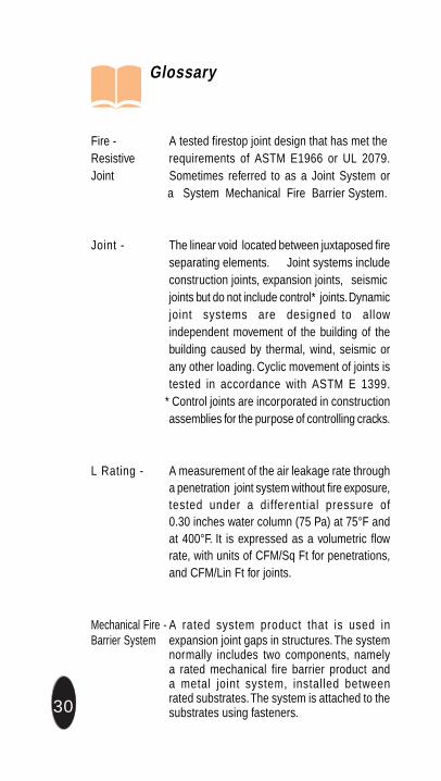
Fire - A tested firestop joint design that has met theResistive requirements of ASTM E1966 or UL 2079.Joint Sometimes referred to as a Joint System or
a System Mechanical Fire Barrier System.
Joint - The linear void located between juxtaposed fireseparating elements. Joint systems includeconstruction joints, expansion joints, seismicjoints but do not include control* joints. Dynamicjoint systems are designed to allowindependent movement of the building of thebuilding caused by thermal, wind, seismic orany other loading. Cyclic movement of joints istested in accordance with ASTM E 1399.
* Control joints are incorporated in constructionassemblies for the purpose of controlling cracks.
L Rating - A measurement of the air leakage rate througha penetration joint system without fire exposure,tested under a differential pressure of0.30 inches water column (75 Pa) at 75°F andat 400°F. It is expressed as a volumetric flowrate, with units of CFM/Sq Ft for penetrations,and CFM/Lin Ft for joints.
Mechanical Fire - A rated system product that is used inBarrier System expansion joint gaps in structures. The system
normally includes two components, namelya rated mechanical fire barrier product anda metal joint system, installed betweenrated substrates. The system is attached to thesubstrates using fasteners.
Glossary
30

Mullion - The vertical suppor tive member(s) withinacurtain wall assembly.
Membrane - An opening for a penetrant which is only on oneside of an assembly. The penetrantchanges directions upon entering the assemblyand may exit at another location.
Nominal - The joint width at the time of installation and notJoint Width the movement capability. This differs from
theJoint Width gap between substrates at thetime the gap is constructed, e.g. concretepoured in the floors. This dimension, that theJoint Gap is constructed is critical to theselection of the systems specified and used.The gap width should be formed usingtemperature data and the engineer’s totaldesign movement expected at the joint lines andthen refer to them Temperature/AdjustmentTable. Widths then will be assigned width basedon temperature.
Penetrant - The tems(s) which breaches a rated assembly.Usually pipes, conduits, wires, ducts, or cabletrays.
Perimeter - The combination of the non-structural exteriorwall assembly, perimeter joint protection,and floor assembly That provides fire resistanceto prevent the passage of fire from floor to floorat the building’s exterior.
Perimeter - The linear gap located between juxtaposedJoint exterior wall assembly and floor assemblydesigned to accommodate various degrees ofmovements induced by thermal differentials,wind loads and seismicity. Tested in accordancewith ASTM E1399.
Glossary
31
Barr ier

Safing - Another term used to refer to the gap betweenArea a rated floor and a curtain wall.
Splice - The connection or junction within the length ofa joint system.
Through - An opening and/or penetrant that passes fullyPenetration Penetration through a rated assembly.
Through - A tested firestop design that has metPenetration the requirements of ASTM E814, or UL 1479.FirestopSystem
Transom - The horizontal supportive member(s) withina curtain wall assembly.
T Rating - The amount of t ime that a firestopsystem prevents the temperature on the non-fire side from rising 325 F above ambientwhen tested in accordance with ASTM E-814or UL 1479.
Void - An opening or region of a space within a lineargap which is considered static in nature. Theseareas include the region within the flutes ofa steel deck, the region above a steel top track,and irregularities in the gap spacing.
W Rating - Measures resistance of a firestop productto standing water in buildings. The test simulateswater on a firestop system for 72 hours under a3’ head of water.
References: Annual Book Of ASTM Standard
Glossary
32

TheSystemApproach:· UL Approved - No Such Thing (Only AHJ Approves Products/Systems)
· UL Classified - Lab has used the country requirementsto evaluate the product for specific hazardsor properties
· UL Listed - Passes the standard test and is in the lab’s directory
Navigating UL:· Example 1: UL Classified – Through Penetratrarion
Firestop Systemso First Alpha Character – Signifies what is being penetrated
§ F = Floors§ W = Walls§ C = Walls and Floors
C-AJ-1079 • Combination – Floor or Wall
o Following Alpha Characters(s) -Wall or Floor Construction Type§ A = Concrete Floors 5 inch thick§ B = Concrete Floors 5 inch thick§ C = Framed Floors§ D = Steel decks in marine Vessels§ E-I = Reserved for future use§ J = Concrete or masonry walls 8 inch thick§ K = Concrete or masonry walls 8 inch thick§ L = Framed walls§ M = Bulkheads in marine Vessels§ N-Z = Reserved for future use
C-AJ-1079 • Construction Type of Floor or Wall
<_
Th
e S
yste
m A
pp
roac
h:
33
_>
>_
_<

o Numeric Component – First digit identifies the typeof penetrant, next three are sequential system numbering
• C-AJ-1079 • Penetrant Type
• C-AJ-1079 • Individual system number
o 0000-0999 = No penetranto 1000-1999 = Metallic pipe, conduit or Tubingo 2000-2999 = Nonmetallic pipe, conduit or tubingo 3000-3999 = Electric Cableso 4000-4999 = Cable trays with electrical Cableso 5000-5999 = Insulated pipeso 6000-6999 = Buswayso 7000-7999 = HVAC ductso 8000-8999 = Mixed multiple Penetrationso 9000-9999 = Reserved for future uses
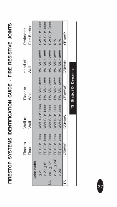
· Example 2: UL System – Joint Systems• HW-D-0034
• Barriers that form the join· First Two Alpha Characters – identify the type of joint system· FF = Floor-to-Floor· WW = Wall-to-Wall· FW = Floor-to-Wall· HW = Head-of-Wall
• HW-D-0034 • Movement: Static or Dynamic
· D = Dynamic (movement capabilities)· S = Static (no movement capabilities)
· HW-D-0034 • Joint Width
· Numeric Component – first digit identifies the width of thejoint system, next three are numberingsequential system
• HW-D-0034 • Individual System Number
o 0000-0999 = joint 2 incho 1000-1999 = joint > 2 inch 6 incho 2000-2999 = joint > 6 inch 12 incho 3000-3999 = joint > 12 inch 24 incho 4000-4999 = joint > 24 inch
<_<
_
_<<_
34

Movement In Construction Jointsand Curtain Wall Systems:
· Joint systems with movement capabilities are noted throughthe appearance of a Class I, II and/orIII designation included as part of the headinginformation. The definitions of the movementclass are as follows:
§ Class I:· Minimum 500 cycles @ a minimum
of 1 cycle/minute;
§ Class II:· Minimum 500 cycles @ a minimum
of 10 cycles/minute
§ Class III:· Minimum 100 cycles @ a minimum
of 30 cycles/minute
35

Blan
k O
peni
ngs
CAJ
0###
CAJ
0###
WL
0###
FC0#
##W
J0#
##FE
0###
Met
allic
CAJ
1###
CAJ
1###
WL
1###
FC 1
###
WJ
1###
FE 1
###
Non
met
allic
CAJ
2###
CAJ
2###
WL
2###
FC 2
###
WJ
2###
FE 2
###
Cabl
esCA
J 3#
##CA
J 3#
##W
L 3#
##FC
3##
#W
J 3
###
FE 3
###
Cabl
e Tr
ays
CAJ
4###
CAJ
4###
WL
4###
FC4#
##W
J 4#
##FE
4###
Insu
late
d M
etal
CAJ
5###
CAJ
5###
WL
5###
FC 5
###
WJ
5###
FE 5
###
Bus
Duc
tCA
J6#
##CA
J6#
##W
L6#
##FC
6###
WJ
6###
FE6#
##
Met
al D
ucts
CAJ
7###
CAJ
7###
WL
7###
FC 7
###
w/o
Dam
pers
WJ
7###
FE 7
###
Mix
ed M
ultip
leCA
J 8#
##CA
J 8#
##W
L 8#
##FC
8##
#W
J 8#
##FE
8##
#
FIR
ES
TO
P
SY
ST
EM
S
IDE
NT
IFIC
AT
ION
G
UID
E
- P
EN
ET
RA
TIO
NS
CON
CRET
E F
LOO
RCO
NCR
ETE
WAL
LG
YPSU
M W
ALL
WO
OD
O
RST
EEL
FRAM
ED F
LOO
RPe
netr
ants
UL
IT
SU
LI
TS
UL
ITS
UL
ITS
FS50
0-69
9FD
FS50
0-69
9FG
FS50
0-69
9FA
FS50
0-69
9FB
FS50
0-69
9FD
FS50
0-69
9FC
FS50
0-69
9FE
TBD
TBD
FS50
0-69
9WG
FS10
0-29
9WB
FS10
0-29
9WC
TBD
TBD
FS10
0-29
9WA
FS10
0-29
9WD
FS10
0-29
9WE
FS10
0-29
9WD
TBD
TBD
FS10
0-29
9WG
FS10
0-29
9WA
FS10
0-29
9WB
FS10
0-29
9WE
FS10
0-29
9WC
FS10
0-29
9WD
FS10
0-29
9WD
TBD
TBD
FS10
0-29
9FG
FS10
0-29
9FA
FS10
0-29
9FB
FS10
0-29
9FD
FS10
0-29
9FD
FS10
0-29
9FC
FS10
0-29
9FE
FIR
ES
TOP
SY
STE
MS
ID
EN
TIFI
CA
TIO
N G
UID
E -
FIR
E R
ES
ISTI
VE
JO
INTS
UL
Flo
or to
Wal
l to
Flo
or to
Hea
d of
Per
imet
erF
loor
Wal
lW
all
Wal
lF
ire B
arrie
rJo
int
Wid
th
< 2
"F
F-S
/D*-
0###
WW
-S
/D*-
0###
FW
-S/D
*-0#
##H
W-S
/D*-
0###
CW
-S/D
*-0#
##>
2";
< 6
"F
F-S
/D*-
1###
WW
-S/D
*-1#
##F
W-S
/D*-
1###
HW
-S/D
*-1#
##C
W-S
/D*-
1###
>6"
, < 1
2”F
F-S
/D*-
2###
WW
-S/D
*-2#
##F
W-S
/D*-
2###
HW
-S/D
*-2#
##C
W-S
/D*-
2###
>12
", <
24"
FF
-S/D
*-3#
##W
W-S
/D*-
3###
FW
-S/D
*-3#
##H
W-S
/D*-
3###
N/A
> 2
4"F
F-S
/D*-
4###
WW
-S/D
*-4#
##F
W-S
/D*-
4###
HW
-S/D
*-4#
##N
/AIT
S
CEJ#
##F
CEJ#
##W
CEJ#
##W
FCE
J###
HCE
J###
P
*S=
Sta
tic
/D=
Dy
na
mic
37

NOTES


IFC Membership List
For a full list of membership including non-voting members such as contractors, codeofficials, architects, engineers, and relatedassociations, check the IFC website at:
www.firestop.org
© “Inspection Manual For Firestopped ThroughPenetrations, Joints and Perimeter Fire Barrier Systems”Copyright 2007, International Firestop Council.
All Rights Reserved. This document may not bereproduced in any form or by any means without theadvance written Permission of the:
International Firestop Councilwww.firestop.org
(877) 241-3769