poc type 4 safety light curtains - platt.com filepresence sensing safety devices poc type 4 safety...
TRANSCRIPT
Presence Sensing Safety Devices
POC Type 4 Safety Light Curtains
2-30Visit our website: www.ab.com/catalogs
Publication S117-CA001A-EN-P
GuardShield Safe 4
General
Princip
les2-O
pto
-electronics
Safety S
witches
Op
erator
InterfaceLo
gic
Po
wer
R
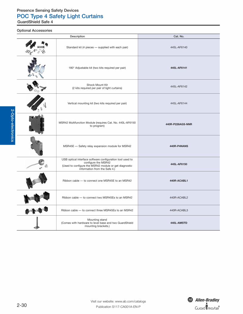
Optional Accessories
Description Cat. No.
Standard kit (4 pieces — supplied with each pair) 445L-AF6140
180° Adjustable kit (two kits required per pair) 445L-AF6141
Shock Mount Kit(2 kits required per pair of light curtains) 445L-AF6142
Vertical mounting kit (two kits required per pair) 445L-AF6144
MSR42 Multifunction Module (requires Cat. No. 440L-AF6150to program) 440R-P226AGS-NNR
MSR45E — Safety relay expansion module for MSR42 440R-P4NANS
USB optical interface software configuration tool used toconfigure the MSR42
(Used to configure the MSR42 module or get diagnosticinformation from the Safe 4.)
445L-AF6150
Ribbon cable — to connect one MSR45E to an MSR42 440R-ACABL1
Ribbon cable — to connect two MSR45Es to an MSR42 440R-ACABL2
Ribbon cable — to connect three MSR45Es to an MSR42 440R-ACABL3
Mounting stand(Comes with hardware to level base and two GuardShield
mounting brackets.)440L-AMSTD
Presence Sensing Safety Devices
POC Type 4 Safety Light Curtains
2-37Visit our website: www.ab.com/catalogs
Publication S117-CA001A-EN-P
GuardShield Micro 400
Gen
eral
Pri
ncip
les
2-O
pto
-ele
ctro
nics
Saf
ety
Sw
itche
sO
per
ato
rIn
terf
ace
Log
icP
ow
er
R
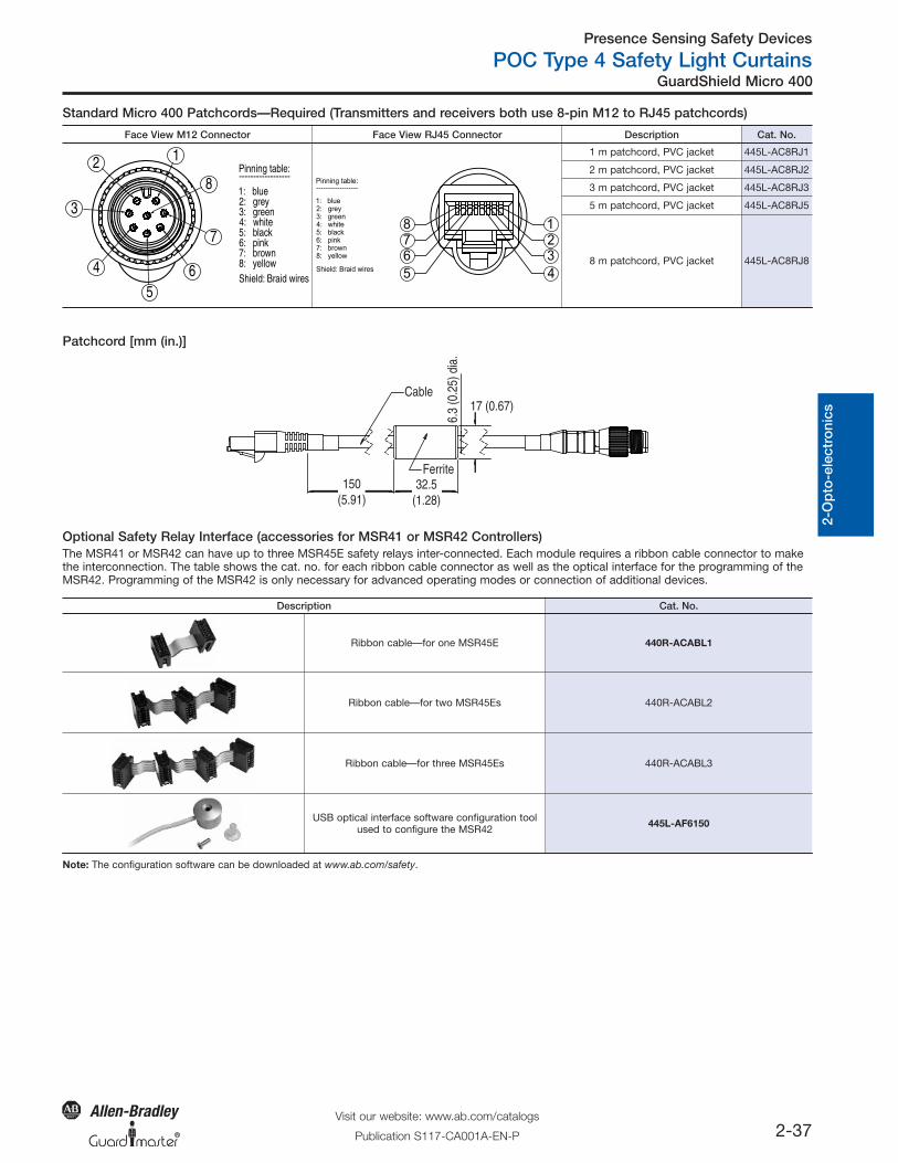
Face View M12 Connector Face View RJ45 Connector Description Cat. No.
Pinning table:------------------1: blue2: grey3: green4: white5: black6: pink7: brown8: yellowShield: Braid wires
12
3
4
56
7
8 Pinning table:------------------
1: blue2: grey3: green4: white5: black6: pink7: brown8: yellow
Shield: Braid wires
123
45
678
1 m patchcord, PVC jacket 445L-AC8RJ1
2 m patchcord, PVC jacket 445L-AC8RJ2
3 m patchcord, PVC jacket 445L-AC8RJ3
5 m patchcord, PVC jacket 445L-AC8RJ5
8 m patchcord, PVC jacket 445L-AC8RJ8
Patchcord [mm (in.)]
Description Cat. No.
Ribbon cable—for one MSR45E 440R-ACABL1
Ribbon cable—for two MSR45Es 440R-ACABL2
Ribbon cable—for three MSR45Es 440R-ACABL3
USB optical interface software configuration toolused to configure the MSR42 445L-AF6150
Note: The configuration software can be downloaded at www.ab.com/safety.
Standard Micro 400 Patchcords—Required (Transmitters and receivers both use 8-pin M12 to RJ45 patchcords)
Ferrite6.
3 (0
.25)
dia
.
17 (0.67)
150(5.91)
32.5(1.28)
Cable
The MSR41 or MSR42 can have up to three MSR45E safety relays inter-connected. Each module requires a ribbon cable connector to makethe interconnection. The table shows the cat. no. for each ribbon cable connector as well as the optical interface for the programming of theMSR42. Programming of the MSR42 is only necessary for advanced operating modes or connection of additional devices.
Optional Safety Relay Interface (accessories for MSR41 or MSR42 Controllers)
Presence Sensing Safety Devices
POC Type 2 Safety Light Curtains
2-53Visit our website: www.ab.com/catalogs
Publication S117-CA001A-EN-P
GuardShield Safe 2
Gen
eral
Pri
ncip
les
2-O
pto
-ele
ctro
nics
Saf
ety
Sw
itche
sO
per
ato
rIn
terf
ace
Log
icP
ow
er
R
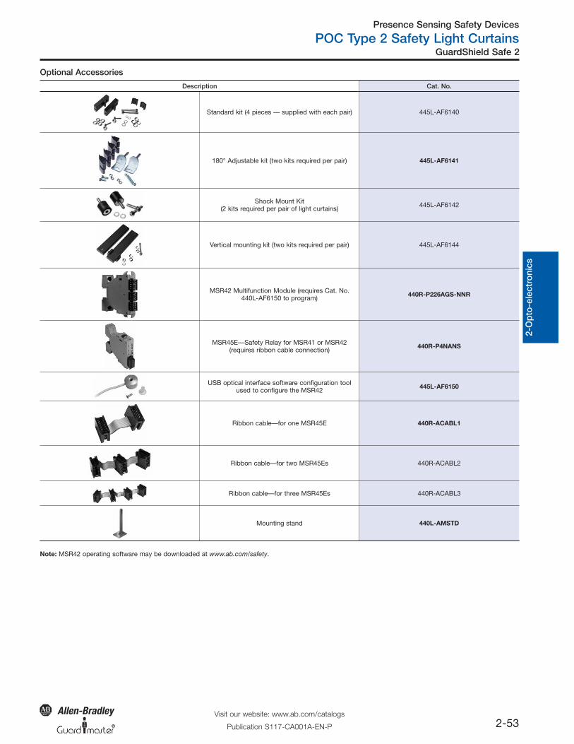
Optional Accessories
Description Cat. No.
Standard kit (4 pieces — supplied with each pair) 445L-AF6140
180° Adjustable kit (two kits required per pair) 445L-AF6141
Shock Mount Kit(2 kits required per pair of light curtains) 445L-AF6142
Vertical mounting kit (two kits required per pair) 445L-AF6144
MSR42 Multifunction Module (requires Cat. No.440L-AF6150 to program) 440R-P226AGS-NNR
MSR45E—Safety Relay for MSR41 or MSR42(requires ribbon cable connection) 440R-P4NANS
USB optical interface software configuration toolused to configure the MSR42 445L-AF6150
Ribbon cable—for one MSR45E 440R-ACABL1
Ribbon cable—for two MSR45Es 440R-ACABL2
Ribbon cable—for three MSR45Es 440R-ACABL3
Mounting stand 440L-AMSTD
Note: MSR42 operating software may be downloaded at www.ab.com/safety.
Presence Sensing Safety Devices
PAC Type 4 Safety Light Curtains
2-67Visit our website: www.ab.com/catalogs
Publication S117-CA001A-EN-P
GuardShield Safe 4 PAC
Gen
eral
Pri
ncip
les
2-O
pto
-ele
ctro
nics
Saf
ety
Sw
itche
sO
per
ato
rIn
terf
ace
Log
icP
ow
er
R
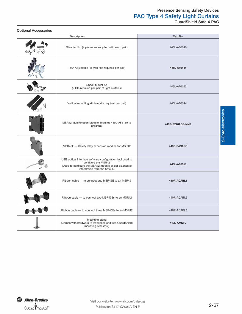
Optional Accessories
Description Cat. No.
Standard kit (4 pieces — supplied with each pair) 445L-AF6140
180° Adjustable kit (two kits required per pair) 445L-AF6141
Shock Mount Kit(2 kits required per pair of light curtains) 445L-AF6142
Vertical mounting kit (two kits required per pair) 445L-AF6144
MSR42 Multifunction Module (requires 440L-AF6150 toprogram) 440R-P226AGS-NNR
MSR45E — Safety relay expansion module for MSR42 440R-P4NANS
USB optical interface software configuration tool used toconfigure the MSR42
(Used to configure the MSR42 module or get diagnosticinformation from the Safe 4.)
445L-AF6150
Ribbon cable — to connect one MSR45E to an MSR42 440R-ACABL1
Ribbon cable — to connect two MSR45Es to an MSR42 440R-ACABL2
Ribbon cable — to connect three MSR45Es to an MSR42 440R-ACABL3
Mounting stand(Comes with hardware to level base and two GuardShield
mounting brackets.)440L-AMSTD
R
Logic
Single-Function Safety Relays
5-21Visit our website: www.ab.com/catalogs
Publication S117-CA001A-EN-P
MSR41
Gen
eral
Pri
ncip
les
9-10
-Saf
ety
Ap
plic
atio
ns11
-Cat
. No
.In
dex
5-S
afet
y R
elay
sP
ow
er
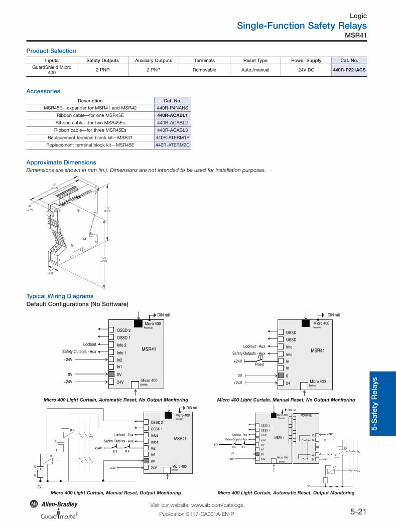
Product Selection
Accessories
Approximate DimensionsDimensions are shown in mm (in.). Dimensions are not intended to be used for installation purposes.
Inputs Safety Outputs Auxiliary Outputs Terminals Reset Type Power Supply Cat. No.GuardShield Micro
400 2 PNP 2 PNP Removable Auto./manual 24V DC 440R-P221AGS
Description Cat. No.
MSR45E—expander for MSR41 and MSR42 440R-P4NANS
Ribbon cable—for one MSR45E 440R-ACABL1
Ribbon cable—for two MSR45Es 440R-ACABL2
Ribbon cable—for three MSR45Es 440R-ACABL3
Replacement terminal block kit—MSR41 440R-ATERM1P
Replacement terminal block kit—MSR45E 440R-ATERM2C
22.5(0.89)
125(4.92)
110(4.33)
95(3.74)
111(4.37)
Typical Wiring DiagramsDefault Configurations (No Software)
0V
24V
OSSD 1
OSSD 2
Micro 400Emitter
Micro 400Receiver
In1
In2
Info 1
Info 2
0V
DIN rail
+24V
+24V
Lockout
Safety Outputs - Aux MSR41
Reset
0
24
OSSD
OSSD
Micro 400Emitter
Micro 400Receiver
In
In
Info
Info
0V
DIN rail
+24V
+24V
Lockout - Aux
Safety Outputs - AuxMSR41
Micro 400 Light Curtain, Automatic Reset, No Output Monitoring Micro 400 Light Curtain, Manual Reset, No Output Monitoring
K 4K 3
0V
24V
OSSD 1
OSSD 2
Micro 400Emitter
Micro 400Receiver
In1
In2
Info1
Info2
DIN rail
+24V
Lockout - Aux
Safety Outputs - Aux
0V
K 3
C
K 4
+24VC
R
R
MSR41 MSR41
0V
24V
OSSD 1
OSSD 2
Micro 400Emitter
Micro 400Receiver
In1
In2
Info1
Info2
0V
DIN rail
MSR45E
24
23
14
13
K 3
C
K 4
+24V
0V +24V
+24V
K 4K 3+24V
Lockout - Aux
Safety Outputs - Aux
Micro 400 Light Curtain, Manual Reset, Output Monitoring Micro 400 Light Curtain, Automatic Reset, Output Monitoring
01_SF_SafetyRelays 5/6/2010 11:23 AM Page 5-21
R
Logic
Specialty Safety Relays
5-53Visit our website: www.ab.com/catalogs
Publication S117-CA001A-EN-P
MSR42 Control Module
Gen
eral
Pri
ncip
les
9-10
-Saf
ety
Ap
plic
atio
ns11
-Cat
. No
.In
dex
5-S
afet
y R
elay
sP
ow
er
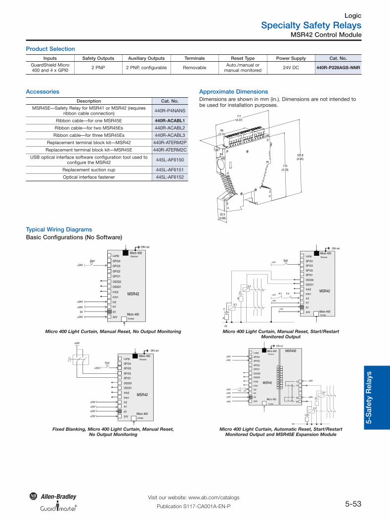
Product Selection
Inputs Safety Outputs Auxiliary Outputs Terminals Reset Type Power Supply Cat. No.GuardShield Micro400 and 4 x GPI0 2 PNP 2 PNP, configurable Removable Auto./manual or
manual monitored 24V DC 440R-P226AGS-NNR
Approximate Dimensions
111(4.37)
95(3.74)
22.5(0.89)
110(4.33)
125.8(4.95)
Accessories
Description Cat. No.
MSR45E—Safety Relay for MSR41 or MSR42 (requiresribbon cable connection) 440R-P4NANS
Ribbon cable—for one MSR45E 440R-ACABL1
Ribbon cable—for two MSR45Es 440R-ACABL2
Ribbon cable—for three MSR45Es 440R-ACABL3
Replacement terminal block kit—MSR42 440R-ATERM2P
Replacement terminal block kit—MSR45E 440R-ATERM2C
USB optical interface software configuration tool used toconfigure the MSR42 445L-AF6150
Replacement suction cup 445L-AF6151
Optical interface fastener 445L-AF6152
Typical Wiring DiagramsBasic Configurations (No Software)
0V
24V
OSSD1
OSSD2
Micro 400Emitter
Micro 400Receiver
In1
In2
Info1
Info2
GPIO1
GPIO2
GPIO3
GPIO4
Lamp
0V
+24V
DIN rail
Start
+24V
+24V
+24V
MSR42
0V
24V
OSSD1
OSSD2
Micro 400 Emitter
Micro 400Receiver
In1
In2
Info1
Info2
GPIO1
GPIO2
GPIO3
GPIO4
Lamp
0V
DIN rail
K 4
K 3
C
K 4
Start+24V
+24V
+24V K 3
+24VC
R
R
MSR42
Micro 400 Light Curtain, Manual Reset, No Output Monitoring Micro 400 Light Curtain, Manual Reset, Start/RestartMonitored Output
0V
24V
OSSD1
OSSD2
Micro 400Emitter
Micro 400Receiver
In1
In2
Info1
Info2
GPIO1
GPIO2
GPIO3
GPIO4
Lamp
+24V
DIN rail
Start
+24V
MSR42
+24V
+24V
+24V
+24V
MSR42
0V
24V
OSSD1
OSSD2
Micro 400
Emitter
Micro 400Receiver
In1
In2
Info1
Info2
GPIO1
GPIO2
GPIO3
GPIO4
Lamp
0V
+24V
DIN rail
MSR45E
24
23
14
13
K 3 K 4
K 3
C
K 4
+24V
+24V
+24V
+24V
+24V
+24V
+24V
Fixed Blanking, Micro 400 Light Curtain, Manual Reset,No Output Monitoring
Micro 400 Light Curtain, Automatic Reset, Start/RestartMonitored Output and MSR45E Expansion Module
Dimensions are shown in mm (in.). Dimensions are not intended tobe used for installation purposes.
02_Spec_SafetyRelays 5/6/2010 11:28 AM Page 5-53
R
Logic
Expansion Safety Relays
5-77Visit our website: www.ab.com/catalogs
Publication S117-CA001A-EN-P
MSR45E
Gen
eral
Pri
ncip
les
9-10
-Saf
ety
Ap
plic
atio
ns11
-Cat
. No
.In
dex
5-S
afet
y R
elay
sP
ow
er
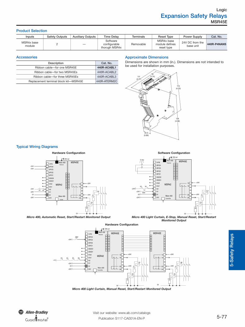
Product Selection
Inputs Safety Outputs Auxiliary Outputs Time Delay Terminals Reset Type Power Supply Cat. No.
MSR4x basemodule 2 —
Softwareconfigurable
thorugh MSR4xRemovable
MSR4x basemodule defines
reset type
24V DC from thebase unit 440R-P4NANS
Accessories
Description Cat. No.
Ribbon cable—for one MSR45E 440R-ACABL1
Ribbon cable—for two MSR45Es 440R-ACABL2
Ribbon cable—for three MSR45Es 440R-ACABL3
Replacement terminal block kit—MSR45E 440R-ATERM2C
Approximate Dimensions
111(4.37)
95(3.74)
22.5(0.89)
110(4.33)
126(4.96)
Typical Wiring Diagrams
Hardware Configuration Software Configuration
MSR42
0V
24V
OSSD1
OSSD2
Micro 400
Emitter
Micro 400Receiver
In1
In2
Info1
Info2
GPIO1
GPIO2
GPIO3
GPIO4
Lamp
0V
+24V
DIN rail
MSR45E
24
23
14
13
K3 K4
K3
C
K4
0V
+24V
+24V
+24V
+24V
+24V
+24V
0V
MSR45E
24
23
14
13
K 3
C
K 4
+24V
+24V
0V
24V
OSSD1
OSSD2
Micro 400Transmitter
Micro 400Receiver
In1
In2
Info1
Info2
GPIO1
GPIO2
GPIO3
GPIO4
Lamp
0V
+24V
DIN rail
Start
K4K3
E-stop
MSR42
+24V
+24V
Micro 400, Automatic Reset, Start/Restart Monitored Output Micro 400 Light Curtain, E-Stop, Manual Reset, Start/RestartMonitored Output
Hardware Configuration
0V
MSR45E
24
23
14
13
K3
C
K4
0V
24V
OSSD1
OSSD2
Micro 400Transmitter
Micro 400Receiver
In1
In2
Info1
Info2
GPIO1
GPIO2
GPIO3
GPIO4
Lamp
+24V
DIN rail
Start
0V
24
23
14
13
K5
C
K6
K4+24V
K3 K6K5
MSR45E
MSR42
+24V
+24V
0V
+24V
+24V
+24V
+24V
Micro 400 Light Curtain, Manual Reset, Start/Restart Monitored Output
Dimensions are shown in mm (in.). Dimensions are not intended tobe used for installation purposes.
03_Other_SafetyRelays 5/6/2010 11:34 AM Page 5-77
Logic
Configurable Safety Relays
R5-114Visit our website: www.ab.com/catalogs
Publication S117-CA001A-EN-P
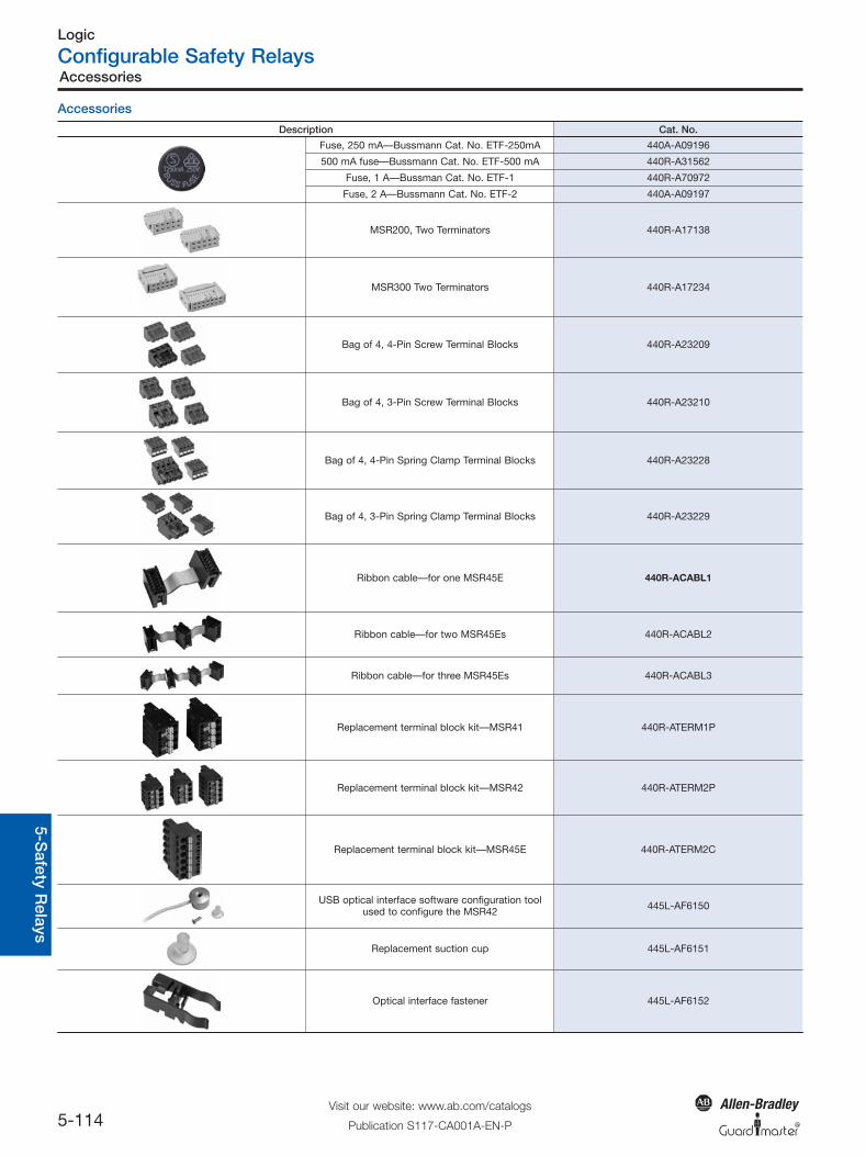
Accessories
General
Princip
les9-
10-Safety
Ap
plicatio
ns11-C
at. No
.Ind
ex5-S
afety Relays
Po
wer
Accessories
Description Cat. No.
Fuse, 250 mA—Bussmann Cat. No. ETF-250mA 440A-A09196
500 mA fuse—Bussmann Cat. No. ETF-500 mA 440R-A31562
Fuse, 1 A—Bussman Cat. No. ETF-1 440R-A70972
Fuse, 2 A—Bussmann Cat. No. ETF-2 440A-A09197
MSR200, Two Terminators 440R-A17138
MSR300 Two Terminators 440R-A17234
Bag of 4, 4-Pin Screw Terminal Blocks 440R-A23209
Bag of 4, 3-Pin Screw Terminal Blocks 440R-A23210
Bag of 4, 4-Pin Spring Clamp Terminal Blocks 440R-A23228
Bag of 4, 3-Pin Spring Clamp Terminal Blocks 440R-A23229
Ribbon cable—for one MSR45E 440R-ACABL1
Ribbon cable—for two MSR45Es 440R-ACABL2
Ribbon cable—for three MSR45Es 440R-ACABL3
Replacement terminal block kit—MSR41 440R-ATERM1P
Replacement terminal block kit—MSR42 440R-ATERM2P
Replacement terminal block kit—MSR45E 440R-ATERM2C
USB optical interface software configuration toolused to configure the MSR42 445L-AF6150
Replacement suction cup 445L-AF6151
Optical interface fastener 445L-AF6152
05_Config_SafetyRelays 5/6/2010 11:41 AM Page 5-114
Safety Applications and Wiring Diagrams
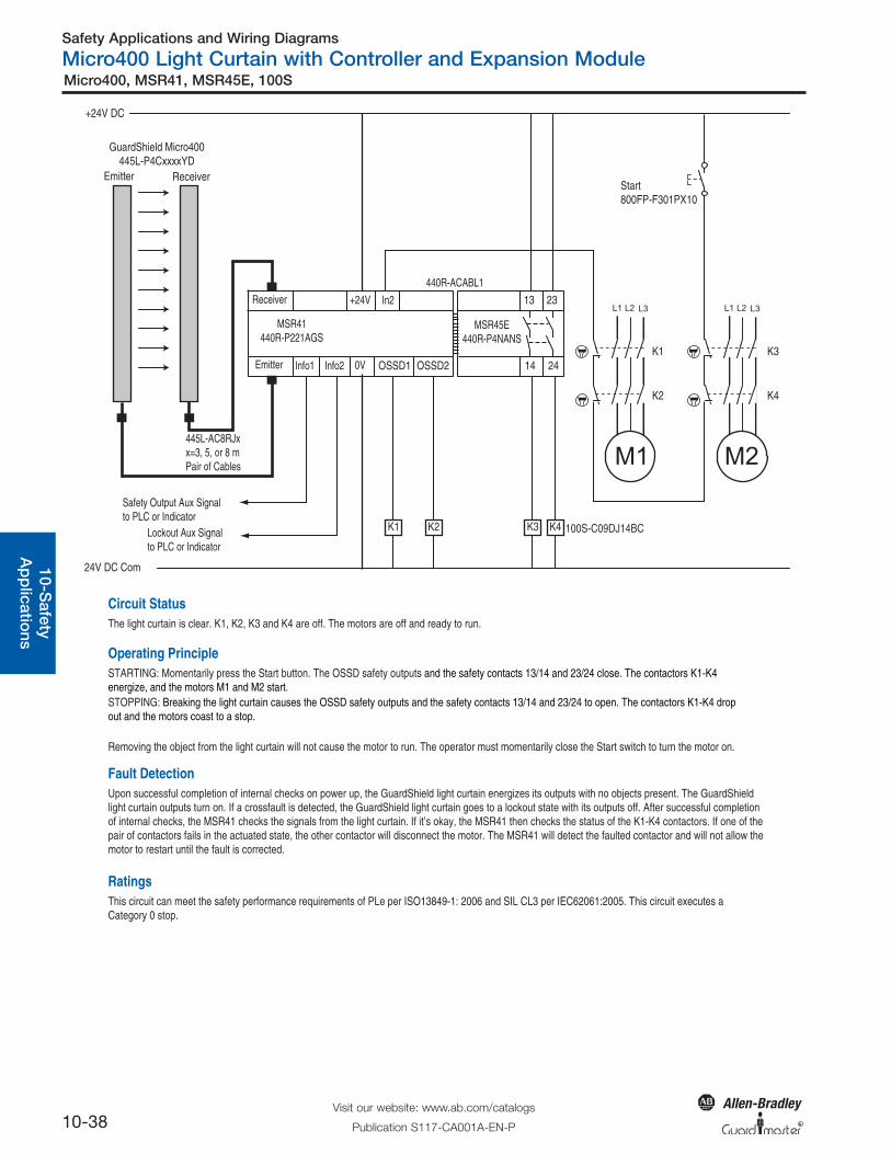
Micro400 Light Curtain with Controller and Expansion Module
10-38Visit our website: www.ab.com/catalogs
Publication S117-CA001A-EN-P
Micro400, MSR41, MSR45E, 100S
R
General
Princip
les9-
10-Safety
Ap
plicatio
nsO
perato
rInterface
Log
icP
ow
er
In2
440R-ACABL1
Info1 Info2
Lockout Aux Signalto PLC or Indicator
Safety Output Aux Signalto PLC or Indicator
0V
+24V
Emitter
Receiver
445L-AC8RJxx=3, 5, or 8 mPair of Cables
MSR41440R-P221AGS
OSSD1 OSSD2
+24V DC
24V DC Com
Start800FP-F301PX10
M2
L1 L2 L3
K3
K4
K1
M1
L1 L2 L3
K2 K3 100S-C09DJ14BCK4
MSR45E440R-P4NANS
2414
13 23
ReceiverEmitter
GuardShield Micro400445L-P4CxxxxYD
K1
K2
Circuit StatusThe light curtain is clear. K1, K2, K3 and K4 are off. The motors are off and ready to run.
Operating PrincipleSTARTING: Momentarily press the Start button. The OSSD safety outputs and the safety contacts 13/14 and 23/24 close. The contactors K1-K4 energize, and the motors M1 and M2 start.STOPPING: Breaking the light curtain causes the OSSD safety outputs and the safety contacts 13/14 and 23/24 to open. The contactors K1-K4 drop out and the motors coast to a stop.
Removing the object from the light curtain will not cause the motor to run. The operator must momentarily close the Start switch to turn the motor on.
Fault DetectionUpon successful completion of internal checks on power up, the GuardShield light curtain energizes its outputs with no objects present. The GuardShield light curtain outputs turn on. If a crossfault is detected, the GuardShield light curtain goes to a lockout state with its outputs off. After successful completion of internal checks, the MSR41 checks the signals from the light curtain. If it’s okay, the MSR41 then checks the status of the K1-K4 contactors. If one of the pair of contactors fails in the actuated state, the other contactor will disconnect the motor. The MSR41 will detect the faulted contactor and will not allow the motor to restart until the fault is corrected.
RatingsThis circuit can meet the safety performance requirements of PLe per ISO13849-1: 2006 and SIL CL3 per IEC62061:2005. This circuit executes a Category 0 stop.
Safety Applications and Wiring Diagrams
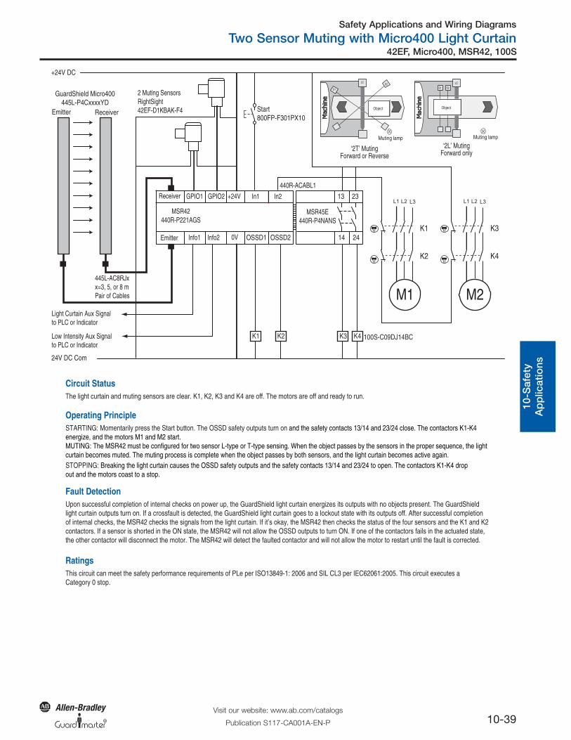
Two Sensor Muting with Micro400 Light Curtain
10-39Visit our website: www.ab.com/catalogs
Publication S117-CA001A-EN-P
42EF, Micro400, MSR42, 100S
R
Gen
eral
Pri
ncip
les
9-10
-Saf
ety
Ap
plic
atio
nsO
per
ato
rIn
terf
ace
Log
icP
ow
er
Muting lamp
Object
LCS2
S1
Muting lamp
LC
S1
Object
S2
In2In1
440R-ACABL1
‘2T’ MutingForward or Reverse
‘2L’ MutingForward only
Info1 Info2
Low Intensity Aux Signalto PLC or Indicator
Light Curtain Aux Signalto PLC or Indicator
0V
2 Muting SensorsRightSight42EF-D1KBAK-F4
GPIO2GPIO1 +24V
Emitter
Receiver
445L-AC8RJxx=3, 5, or 8 mPair of Cables
MSR42440R-P221AGS
OSSD1 OSSD2
+24V DC
24V DC Com
Start800FP-F301PX10
M2
L1 L2 L3
K3
K4
K1
M1
L1 L2 L3
K2 K3 100S-C09DJ14BCK4
MSR45E440R-P4NANS
2414
13 23
ReceiverEmitter
GuardShield Micro400445L-P4CxxxxYD
K1
K2
Circuit StatusThe light curtain and muting sensors are clear. K1, K2, K3 and K4 are off. The motors are off and ready to run.
Operating PrincipleSTARTING: Momentarily press the Start button. The OSSD safety outputs turn on and the safety contacts 13/14 and 23/24 close. The contactors K1-K4 energize, and the motors M1 and M2 start.MUTING: The MSR42 must be configured for two sensor L-type or T-type sensing. When the object passes by the sensors in the proper sequence, the light curtain becomes muted. The muting process is complete when the object passes by both sensors, and the light curtain becomes active again.STOPPING: Breaking the light curtain causes the OSSD safety outputs and the safety contacts 13/14 and 23/24 to open. The contactors K1-K4 drop out and the motors coast to a stop.
Fault DetectionUpon successful completion of internal checks on power up, the GuardShield light curtain energizes its outputs with no objects present. The GuardShield light curtain outputs turn on. If a crossfault is detected, the GuardShield light curtain goes to a lockout state with its outputs off. After successful completion of internal checks, the MSR42 checks the signals from the light curtain. If it’s okay, the MSR42 then checks the status of the four sensors and the K1 and K2 contactors. If a sensor is shorted in the ON state, the MSR42 will not allow the OSSD outputs to turn ON. If one of the contactors fails in the actuated state, the other contactor will disconnect the motor. The MSR42 will detect the faulted contactor and will not allow the motor to restart until the fault is corrected.
RatingsThis circuit can meet the safety performance requirements of PLe per ISO13849-1: 2006 and SIL CL3 per IEC62061:2005. This circuit executes a Category 0 stop.