pneumatic pump
DESCRIPTION
PRESSURE BOOSTER PUMPSTRANSCRIPT
TYPE B160 / TYPE B200
Single acting, Double acting and Two stage
Available in ATEX version
AIR DRIVEN GAS BOOSTERS
www. re sa to . com
2
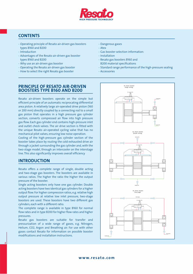
PRINCIPLE OF RESATO AIR-DRIVENBOOSTERS TYPE B160 AND B200
Resato air-driven boosters operate on the simple but
effi cient principle of an automatic reciprocating differential
area piston. A relatively large air-operated drive piston (160
or 200 mm) directly coupled by a connecting rod to a small
gas piston that operates in a high pressure gas cylinder
section, converts compressed air fl ow into high pressure
gas fl ow. Each gas cylinder end contains high-pressure inlet
and outlet check valves. The air drive section is fi tted with
the unique Resato air-operated cycling valve that has no
mechanical pilot valves, ensuring low noise operation.
Cooling of the high-pressure gas cylinder section of the
booster takes place by routing the cold exhausted drive air
through a jacket surrounding the gas cylinder and, with the
two-stage model, through an intercooler on the interstage
line. This also signifi cantly improves overall effi ciency
INTRODUCTION
Resato offers a complete range of single, double acting
and two-stage gas boosters. The boosters are available in
various ratios. The higher the ratio the higher the output
pressure of the booster.
Single acting boosters only have one gas cylinder. Double
acting boosters have two identical gas cylinders for a higher
output fl ow. For higher compression ratios, e.g. relative high
output pressure at relative low inlet pressure, two-stage
boosters are used. These boosters have two different gas
cylinders, each with a different ratio.
The complete range is available in type B160 for normal
fl ow rates and in type B200 for higher fl ow rates and higher
pressures.
Resato gas boosters are suitable for transfer and
pressurization of a wide range of gases, e.g. Nitrogen,
Helium, CO2, Argon and Breathing air. For use with other
gases contact Resato for information on possible booster
modifi cations and installation instructions.
- Operating principle of Resato air-driven gas boosters
types B160 and B200- Introduction
- Advantages of the Resato air-driven gas booster
types B160 and B200- Why use an air-driven gas booster
- Operating the Resato air-driven gas booster
- How to select the right Resato gas booster
- Dangerous gases
- Atex
- Gas booster selection information:
- Installation
- Resato gas boosters B160 and
B200 material specifi cations
- Standard range performance of the high-pressure sealing
- Accessories
CONTENTS
Air supply (Pa)
Supply (Ps)
Outlet (Po)
Air driven booster
(Single Acting)
Air supply (Pa)
Supply (Ps)
Air driven booster
(Two-stage)
Outlet (Po)
Interstage
Air supply (Pa)
Supply (Ps)
Outlet (Po)
Air driven booster
(Double Acting)
www. re sa to . com
3
ADVANTAGES OF RESATO AIR-DRIVEN GAS BOOSTER TYPES B160 AND B200
Suitable for many types of gases because all gas contacted
parts of the high-pressure section are made of special
selected stainless steel and bronze.
Long working life of the seals because the gas boosters
are standard provided with specially engineered polymer
compounds based on low-friction PTFE resins for optimum
piston sealing to accommodate use of a wide range of
gases.
Check valve cartridges can be replaced within minutes.
Due to the use of ceramic materials for the check valves,
long life operation can be guaranteed.
Air drive of the gas booster with only the air piston and
cycling spool as moving parts.
Unlike most other air-driven gas boosters, there are no
mechanical pilot valves and long internal pilot channels
which have a negative infl uence on the reliability and
cycling speed of the gas booster. The air cycling valve is
mounted directly on top of the air cylinder.
Low noise level compared to other air-driven gas boosters
with mechanical pilot valves.
Freezing of the gas booster is avoided by using an air cycling
valve provided with light weight spool for high airfl ow at
low air velocity.
Equal cooling fl ow of high pressure gas cylinder by
symmetric design of the booster.
The high-pressure seal can be replaced within minutes,
without dismantling the air drive section. Costly downtime
is reduced to a minimum.
Standard provided with vent holes to prevent gas from the
high pressure gas section escaping to the air drive section.
Less frictional resistance of the air piston. Unlike other
air-driven gas boosters, the air piston sealing of a Resato
air-driven gas booster is not an O-ring. It is a V-shaped
expanding ring, which needs less preload than an O-ring.
The air piston is provided with PTFE based slydrings
(bearings) for excellent wear-and-slide qualities. The
slydrings increase the service life of the sealing surface
(air cylinder) and the air piston sealing.
Excellent control of fl ow and output pressure due to low
frictional resistance of the air piston, even at low air drive
pressure.
History of proven reliability under severe conditions, for
instance in offshore use.
All pressure and fl ow output is based on 7 bar (100 psi) air
drive pressure instead of 10 bar (150 psi).
WHY USE AN AIR-DRIVENGAS BOOSTER
Compressed air used as a power drive offers enormous
advantages over use of other power drives: risks of
excessive heat, fl ame, spark or shock are reduced
considerably. Apart from that, both output pressure and
fl ow can be controlled by simply regulating the air drive
pressure of the air-driven gas booster. Varying the air
inlet pressure will automatically and accurately adjust the
output pressure. The cycling speed is at a maximum when
the outlet pressure is low. As the outlet pressure builds up,
the cycling speed is reduced until a stall condition is reached
at the desired outlet pressure. The stall pressure can be held
without any further use of energy.
Other gases such as nitrogen or CO2 can be used as
alternatives to drive the gas booster.
Resato air-driven boosters are simple to install, they are
compact and very quick and easy to maintain.
www. re sa to . com
4
OPERATING THE RESATO AIR-DRIVEN GAS BOOSTER
The outlet pressure and fl ow can be controlled by regulating
the air drive pressure with an air pressure regulator. When
compressed air of a certain air pressure is applied to the gas
booster, it will cycle at high speed producing high gas fl ow.
As the outlet pressure increases, the gas booster will start
to work at a lower rate. As long as the total load in the high
pressure cylinder is less than that in the air cylinder, the
gas booster will continue to run. When a balance of loads is
reached, the gas booster stops and no more air is used.
The gas booster will automatically restart when the balance
is disturbed by a outlet pressure drop or by increasing the
air drive pressure. As the frictional resistance of the Resato
air-driven piston is very low, only a small pressure drop or air
drive pressure increase is required to restart the gas booster.
HOW TO SELECT THE RIGHT RESATO BOOSTER
Because gas is a compressible medium, the selection of a
gas booster that best suits your needs is much more critical
than for a liquid pump. The following parameters have to be
considered to determine which gas booster to use:
- Maximum output pressure
- Gas supply pressure to the booster.
Constant or decreasing? The minimum and the maximum
gas supply pressure?
- Flow rate required at a certain pressure or the required fi ll
time of an indicated vessel volume
- Air drive pressure
- Air drive volume
- Type of gas
- External conditions like hazardous areas.
The charts in the following pages may help you in selecting
the proper booster type. Make a selection on pressure fi rst,
then make a selection of the required fl ow rate based on the
gas supply pressure. However, for an accurate gas booster
selection, contact Resato. Our specially developed computer
program will accurately calculate the right booster type for
your application area.
Dangerous gases
For dangerous gases, Resato offers a common leak hole
solution for gas boosters. In case of a leaking seal, gases
are led to a single outlet for outdoor blowing or to be
connected to a sniffl er (code CL). On request, Resato gas
boosters can be built as “oxygen clean” (code OX).
ATEX
As an option, Resato air driven gas boosters can be delivered
in an ATEX 94/9/EC compliant version. The user of the gas
booster is responsible for classifying the area of use, while
identifying the equipment category is the responsibility of
the manufacturer. Resato gas boosters are ATEX approved
for Group II, category 2 zones G & D (code EX).
GAS BOOSTER SELECTION INFORMATION:
B160 - 65 - 2/EX
Diameter of the air-driven piston: 160 mm.
B160 - 65 - 2/EX
Nominal working ratio of the gas booster: 65
B160 - 65 - 2/EX
Double acting type (single acting is indicated by 1;
double stage is indicated with two ratios)
B160 - 65 - 2/EX
Atex version (EX)
INSTALLATION
Resato gas boosters can be mounted in any position.
For maintenance reasons you are advised to mount gas
boosters in horizontal position, using the four thread holes in
the air drive end caps. If it is not possible to use the standard
thread holes, brackets can be used (see Accessories).
The gas boosters will deliver their rated capacity at 7 bar
(100 psi) air drive pressure with the required air fl ow. The air
supply line requires an air pressure regulator to control the
output of the gas booster. Apart from that it is necessary to
mount an oil lubricator and a fi lter/water separator in the
air supply line.
A start/stop air valve can be mounted in the air supply line
on request.

www. re sa to . com
5
GAS
BO
OST
ER T
YPE
TABL
E
Typ
e
Pre
ssu
re
Ma
x.
Str
ok
e
Str
ok
e
Min
ima
l M
ax
imu
m
Act
ua
l M
ax
. ou
tle
t A
ir d
rive
A
ir s
up
ply
G
as
sup
ply
O
utl
et
We
igh
t
ra
tio
co
mp
ress
ion
vo
lum
e
volu
me
su
pp
ly
sup
ply
g
as
ou
tle
t p
ress
ure
(P
o)
pre
ssu
re (
Pa
) co
nn
en
tio
n
con
ne
ctio
n
con
ne
ctio
n
rati
o
rati
o
p
ress
ure
(P
s)
pre
ssu
re (
Ps)
p
ress
ure
(P
o)
up t
o 0
-30
bar
B
160-
2,5-
1 2,
5 1:
10
- 78
5 cc
1,
8 b
ar
(26
psi
) 18
bar
(2
60 p
si)
2,5x
Pa
18 b
ar
(260
psi
) 1-
7 b
ar (1
4-10
0 p
si)
3/4”
BSP
-F
1/2”
NPT
-F
1/2”
NPT
-F
17,5
kg
B16
0-2,
5-2
2,5
1:10
-
1570
cc
1,8
bar
(2
6 p
si)
18 b
ar
(260
psi
) 2,
5xPa
+Ps
18
bar
(2
60 p
si)
1-7
bar
(14-
100
psi
) 3/
4” B
SP-F
1/
2” N
PT-F
1/
2” N
PT-F
22
kg
B20
0-2,
5-2
2,5
1:10
-
2450
cc
1,8
bar
(2
6 p
si)
18 b
ar
(260
psi
) 2,
5xPa
+Ps
18
bar
(2
60 p
si)
1-7
bar
(14-
100
psi
) 3/
4” B
SP-F
1/
2” N
PT-F
1/
2” N
PT-F
29
kgB
200-
4-2
4 1:
10
- 15
70 c
c 2,
8 b
ar
(40
psi
) 28
bar
(4
05 p
si)
4xPa
+Ps
28
bar
(4
05 p
si)
1-7
bar
(14-
100
psi
) 3/
4” B
SP-F
1/
2” N
PT-F
1/
2” N
PT-F
29
kg
up t
o 5
0 b
ar
B16
0-5-
1 5
1:15
-
385
cc
2,4
bar
(3
5 p
si)
35 b
ar
(510
psi
) 5x
Pa
35 b
ar
(510
psi
) 1-
7 b
ar (1
4-10
0 p
si)
3/4”
BSP
-F
1/2”
NPT
-F
1/2”
NPT
-F
17,5
kg
B16
0-5-
2 5
1:15
-
770
cc
2,4
bar
(3
5 p
si)
35 b
ar
(510
psi
) 5x
Pa+
Ps
35 b
ar
(510
psi
) 1-
7 b
ar (1
4-10
0 p
si)
3/4”
BSP
-F
1/2”
NPT
-F
1/2”
NPT
-F
22 k
gB
160-
2,5-
5 1:
2,5
/ 1:
5 1:
35
1:2
785
cc
1,3
bar
(1
9 p
si)
2,
5xPa
5x
Pa+
2xPs
45
bar
(6
50 p
si)
1-7
bar
(14-
100
psi
) 3/
4” B
SP-F
1/
2” N
PT-F
1/
2” N
PT-F
22
kg
B20
0-2,
5-4
1:2,
5 /
1:4
1:35
1:
1,6
1225
cc
1,3
bar
(1
9 p
si)
4,
2xPa
4x
Pa+
1,6x
Ps
45 b
ar
(650
psi
) 1-
7 b
ar (1
4-10
0 p
si)
3/4”
BSP
-F
1/2”
NPT
-F
1/2”
NPT
-F
29 k
gup
to
120
bar
B
200-
8-2
8 1:
15
- 77
0 cc
3,
8 b
ar
(55
psi
) 55
bar
(7
95 p
si)
8xPa
+Ps
55
bar
(7
95 p
si)
1-7
bar
(14-
100
psi
) 3/
4” B
SP-F
1/
2” N
PT-F
1/
2” N
PT-F
29
kg
B
160-
10-1
10
1:
15
- 20
0 cc
4,
8 b
ar
(70
psi
) 70
bar
(1
015
psi
) 10
xPa
70 b
ar
(101
5 p
si)
1-7
bar
(14-
100
psi
) 3/
4” B
SP-F
1/
2” N
PT-F
1/
2” N
PT-F
17
,5 k
gB
160-
10-2
10
1:
15
- 40
0 cc
4,
7 b
ar
(68
psi
) 70
bar
(1
015
psi
) 10
xPa+
Ps
70 b
ar
(101
5 p
si)
1-7
bar
(14-
100
psi
) 3/
4” B
SP-F
1/
2” N
PT-F
1/
2” N
PT-F
22
kg
B16
0-15
-2
15
1:15
-
250
cc
7,4
bar
(110
psi
) 11
0 b
ar
(159
5 p
si)
15xP
a+Ps
11
0 b
ar
(159
5 p
si)
1-7
bar
(14-
100
psi
) 3/
4” B
SP-F
1/
4” N
PT-F
1/
4” N
PT-F
22
kg
B20
0-15
-2
15
1:15
-
400
cc
7,4
bar
(110
psi
) 11
0 b
ar
(159
5 p
si)
15xP
a+Ps
11
0 b
ar
(159
5 p
si)
1-7
bar
(14-
100
psi
) 3/
4” B
SP-F
1/
2” N
PT-F
1/
2” N
PT-F
29
kg
B16
0-15
-1
15
1:15
-
125
cc
7,5
bar
(110
psi
) 11
5 b
ar
(167
0 p
si)
15xP
a 11
5 b
ar
(167
0 p
si)
1-7
bar
(14-
100
psi
) 3/
4” B
SP-F
1/
4” N
PT-F
1/
4” N
PT-F
17
,5 k
gB
160-
5-15
1:
5 /
1:15
1:
50
1:3
385
cc
2,3
bar
(3
3 p
si)
2,
5xPa
15
xPa+
3xPs
11
5 b
ar
(167
0 p
si)
1-7
bar
(14-
100
psi
) 3/
4” B
SP-F
1/
2” N
PT-F
1/
4” N
PT-F
22
kg
B20
0-4-
15
1:4
/ 1:
15
1:60
1:
3,8
785
cc
1,9
bar
(3
0 p
si)
4x
Pa
15xP
a+3,
8xPs
11
5 b
ar
(167
0 p
si)
1-7
bar
(14-
100
psi
) 3/
4” B
SP-F
1/
2” N
PT-F
1/
2” N
PT-F
29
kg
up t
o 2
50 b
ar
B20
0-25
-2
25
1:15
-
250
cc
11,6
bar
(170
psi
) 17
5 b
ar
(254
0 p
si)
25xP
a+Ps
17
5 b
ar
(254
0 p
si)
1-7
bar
(14-
100
psi
) 3/
4” B
SP-F
1/
4” N
PT-F
1/
4” N
PT-F
29
kg
B16
0-30
-1
30
1:15
-
70 c
c 13
,3 b
ar (1
90 p
si)
210
bar
(3
050
psi
) 30
xPa
210
bar
(3
050
psi
) 1-
7 b
ar (1
4-10
0 p
si)
3/4”
BSP
-F
1/4”
NPT
-F
1/4”
NPT
-F
17,5
kg
B16
0-30
-2
30
1:15
-
140
cc
13,2
bar
(190
psi
) 21
0 b
ar
(305
0 p
si)
30xP
a+Ps
21
0 b
ar
(305
0 p
si)
1-7
bar
(14-
100
psi
) 3/
4” B
SP-F
1/
4” N
PT-F
1/
4” N
PT-F
22
kg
B16
0-5-
30
1:5
/ 1:
30
1:10
0 1:
6 38
5 cc
2,
0 b
ar
(30
psi
)
1xPa
30
xPa+
6xPs
21
0 b
ar
(305
0 p
si)
1-7
bar
(14-
100
psi
) 3/
4” B
SP-F
1/
2” N
PT-F
1/
4” N
PT-F
22
kg
B16
0-15
-30
1:15
/ 1
:30
1:30
1:
2 12
5 cc
8,
3 b
ar (1
20 p
si)
15
xPa
30xP
a+2x
Ps
250
bar
(3
625
psi
) 1-
7 b
ar (1
4-10
0 p
si)
3/4”
BSP
-F
1/4”
NPT
-F
1/4”
NPT
-F
22 k
gup
to
350
bar
B
160-
40-1
40
1:
15
- 50
cc
19,1
bar
(275
psi
) 28
5 b
ar
(413
0 p
si)
40xP
a 28
5 b
ar
(413
0 p
si)
1-7
bar
(14-
100
psi
) 3/
4” B
SP-F
M
16x1
,5 H
P-F
M16
x1,5
HP-
F 17
,5 k
gB
160-
40-2
40
1:
15
- 10
0 cc
18
,9 b
ar (2
75 p
si)
285
bar
(4
130
psi
) 40
xPa+
Ps
285
bar
(4
130
psi
) 1-
7 b
ar (1
4-10
0 p
si)
3/4”
BSP
-F
M16
x1,5
HP-
F M
16x1
,5 H
P-F
22 k
gB
200-
45-2
45
1:
15
- 14
0 cc
20
,6 b
ar (3
00 p
si)
310
bar
(4
495
psi
) 45
xPa+
Ps
310
bar
(4
495
psi
) 1-
7 b
ar (1
4-10
0 p
si)
3/4”
BSP
-F
1/4”
NPT
-F
1/4”
NPT
-F
29 k
gB
200-
15-4
5 1:
15 /
1: 4
5 1:
40
1:3
200
cc
8,1
bar
(115
psi
)
7,5x
Pa
45xP
a+3x
Ps
325
bar
(4
715
psi
) 1-
7 b
ar (1
4-10
0 p
si)
3/4”
BSP
-F
1/2”
NPT
-F
1/4”
NPT
-F
29 k
gup
to
500
bar
B
160-
65-2
65
1:
15
- 60
cc
29,6
bar
(430
psi
) 45
0 b
ar
(652
5 p
si)
65xP
a+Ps
45
0 b
ar
(652
5 p
si)
1-7
bar
(14-
100
psi
) 3/
4” B
SP-F
M
16x1
,5 H
P-F
M16
x1,5
HP-
F 22
kg
B20
0-65
-2
65
1:15
-
100
cc
29,7
bar
(430
psi
) 45
0 b
ar
(652
5 p
si)
65xP
a+Ps
45
0 b
ar
(652
5 p
si)
1-7
bar
(14-
100
psi
) 3/
4” B
SP-F
M
16x1
,5 H
P-F
M16
x1,5
HP-
F 29
kg
B16
0-65
-1
65
1:15
-
30 c
c 29
,9 b
ar (4
35 p
si)
450
bar
(6
525
psi
) 65
xPa
450
bar
(6
525
psi
) 1-
7 b
ar (1
4-10
0 p
si)
3/4”
BSP
-F
M16
x1,5
HP-
F M
16x1
,5 H
P-F
17,5
kg
B16
0-15
-65
1:15
/ 1
:65
1:60
1:
4 12
5 cc
7,
5 b
ar (1
10 p
si)
4,
5xPa
65
xPa+
4xPs
45
0 b
ar
(652
5 p
si)
1-7
bar
(14-
100
psi
) 3/
4” B
SP-F
1/
4” N
PT-F
M
16x1
,5 H
P-F
22 k
gB
200-
15-6
5 1:
15 /
1:6
5 1:
55
1:4,
3 20
0 cc
8,
2 b
ar (1
20 p
si)
4,
5xPa
65
xPa+
4,3x
Ps
450
bar
(6
525
psi
) 1-
7 b
ar (1
4-10
0 p
si)
3/4”
BSP
-F
1/2”
NPT
-F
M16
x1,5
HP-
F 29
kg
B20
0-25
-65
1:25
/ 1
:65
1:40
1:
2,6
125
cc
12,2
bar
(175
psi
)
15,6
xPa
65xP
a+2,
6xPs
48
5 b
ar
(703
0 p
si)
1-7
bar
(14-
100
psi
) 3/
4” B
SP-F
1/
4” N
PT-F
M
16x1
,5 H
P-F
29 k
gup
to
800
bar
B
160-
30-6
5 1:
30 /
1: 6
5 1:
30
1:2
70 c
c 17
,8 b
ar (2
60 p
si)
25
,5xP
a 65
xPa+
2xPs
53
5 b
ar
(776
0 p
si)
1-7
bar
(14-
100
psi
) 3/
4” B
SP-F
1/
4” N
PT-F
M
16x1
,5 H
P-F
22 k
gB
200-
100-
2 10
0 1:
15
- 60
cc
46,4
bar
(670
psi
) 69
5 b
ar (
1008
0 p
si)
100x
Pa+
Ps
695
bar
(100
80 p
si)
1-7
bar
(14-
100
psi
) 3/
4” B
SP-F
M
16x1
,5 H
P-F
M16
x1,5
HP-
F 29
kg
B20
0-25
-100
1:
25 /
1:1
00
1:60
1:
4 12
5 cc
11
,8 b
ar (1
70 p
si)
8,
3xPa
10
0xPa
+4x
Ps
710
bar
(102
95 p
si)
1-7
bar
(14-
100
psi
) 3/
4” B
SP-F
1/
4” N
PT-F
M
16x1
,5 H
P-F
29 k
gB
200-
45-1
00
1:45
/ 1
:100
1:
60
1:2,
3 70
cc
2,3
bar
(1
2 p
si)
34
xPa
100x
Pa+
2,3x
Ps
725
bar
(102
95 p
si)
1-7
bar
(14-
100
psi
) 3/
4” B
SP-F
1/
4” N
PT-F
M
16x1
,5 H
P-F
29 k
gB
160-
115-
2 11
5 1:
15
- 36
cc
52,6
bar
(760
psi
) 79
0 b
ar (
1145
5 p
si)
115x
Pa+
Ps
800
bar
(116
00 p
si)
1-7
bar
(14-
100
psi
) 3/
4” B
SP-F
M
16x1
,5 H
P-F
M16
x1,5
HP-
F 22
kg
B16
0-11
5-1
115
1:15
-
18 c
c 53
,1 b
ar (7
70 p
si)
800
bar
(11
600
psi
) 11
5xPa
80
0 b
ar (1
1600
psi
) 1-
7 b
ar (1
4-10
0 p
si)
3/4”
BSP
-F
M16
x1,5
HP-
F M
16x1
,5 H
P-F
17,5
kg
B16
0-30
-115
1:
30 /
1:1
15
1:50
1:
4 70
cc
16,1
bar
(230
psi
)
10,5
xPa
115x
Pa+
4xPs
80
5 b
ar (1
1670
psi
) 1-
7 b
ar (1
4-10
0 p
si)
3/4”
BSP
-F
1/4”
NPT
-F
M16
x1,5
HP-
F 22
kg
up t
o 1
350
bar
B
160-
180-
2 18
0 1:
15
- 22
,6 c
c 82
,2 b
ar (1
190
psi
) 12
35 b
ar (
1791
0 p
si)
180x
Pa+
Ps
1260
bar
(182
70 p
si)
1-7
bar
(14-
100
psi
) 3/
4” B
SP-F
M
16x1
,5 H
P-F
M16
x1,5
HP-
F 22
kg
B20
0-18
0-2
180
1:15
-
36 c
c 82
,5 b
ar (1
195
psi
) 12
35 b
ar (
1791
0 p
si)
180x
Pa+
Ps
1260
bar
(182
70 p
si)
1-7
bar
(14-
100
psi
) 3/
4” B
SP-F
M
16x1
,5 H
P-F
M16
x1,5
HP-
F 29
kg
B16
0-18
0-1
180
1:15
-
11,3
cc
83 b
ar (1
200
psi
) 12
45 b
ar (
1791
0 p
si)
180x
Pa
1260
bar
(182
70 p
si)
1-7
bar
(14-
100
psi
) 3/
4” B
SP-F
M
16x1
,5 H
P-F
M16
x1,5
HP-
F 17
,5 k
gB
160-
30-1
80
1:30
/ 1
: 180
1:
80
1:6
70 c
c 15
,6 b
ar (2
25 p
si)
6x
Pa
180x
Pa+
6xPs
13
30 b
ar (1
9285
psi
) 1-
7 b
ar (1
4-10
0 p
si)
3/4”
BSP
-F
1/4”
NPT
-F
M16
x1,5
HP-
F 22
kg
B16
0-65
-180
1:
65 /
1: 1
80
1:40
1:
3 30
cc
33,3
bar
(480
psi
)
36xP
a 18
0xPa
+3x
Ps
1330
bar
(192
85 p
si)
1-7
bar
(14-
100
psi
) 3/
4” B
SP-F
M
16x1
,5 H
P-F
M16
x1,5
HP-
F 22
kg
B20
0-65
-180
1:
65 /
1: 1
80
1:60
1:
2,8
50 c
c 22
,2 b
ar (3
20 p
si)
36
,7xP
a 18
0xPa
+2,
8xPs
13
30 b
ar (1
9285
psi
) 1-
7 b
ar (1
4-10
0 p
si)
3/4”
BSP
-F
M16
x1,5
HP-
F M
16x1
,5 H
P-F
29 k
g

www. re sa to . com
6
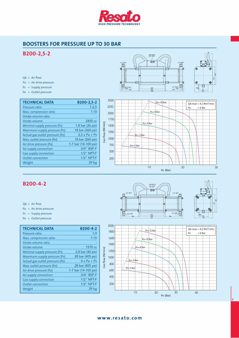
BOOSTERS FOR PRESSURE UP TO 30 BAR
B160-2,5-1
QA = Air fl ow
Pa = Air drive pressure
Ps = Supply pressure
Po = Outlet pressure
AIR INLET
3/4'' BSP
1/2'' NPT
523 540,5
110 M6
170
66
170
239
290 1/2'' NPT
17,5
25,5
B160-2,5-2
QA = Air fl ow
Pa = Air drive pressure
Ps = Supply pressure
Po = Outlet pressure
Po (Bar)
Ga
s fl
ow
(N
l/m
in)
10 20
150
300
450
600
750
900
1050
1200
1350
1500
515 25
Ps= 6 Bar
Ps= 5 Bar
Ps= 4 Bar
Ps= 3 Bar
Ps= 2 Bar
QA max = 2,7 Nm3/min
Pa = 6 Bar
110 M6
170
66
170
239
AIR INLET
3/4'' BSP
1/2'' NPT
1/2'' NPT 1/2'' NPT
1/2'' NPT
17,5 17,5 197,5 197,5
290
310 740
TECHNICAL DATA B160-2,5-1Pressure ratio
Max. compression ratio
Stroke volume ratio
Stroke volume
Minimal supply pressure (Ps)
Maximum supply pressure (Ps)
Actual gas outlet pressure (Po)
Max. outlet pressure (Po)
Air drive pressure (Pa)
Air supply connection
Gas supply connection
Outlet connection
Weight
1:2,51:10
-785 cc
1,8 bar (26 psi)18 bar (260 psi)
2,5 x Pa18 bar (260 psi)
1-7 bar (14-100 psi)3/4'' BSP-F1/2'' NPT-F1/2'' NPT-F
17,5 kg
Po (Bar)
Ga
s fl
ow
(N
l/m
in)
Ps= 6 Bar
Ps= 5 Bar
Ps= 4 Bar
Ps= 3 Bar
Ps= 2 Bar
QA max = 2,7 Nm3/min
Pa = 6 Bar
5 15
100
200
300
400
500
600
10
TECHNICAL DATA B160-2,5-2Pressure ratio
Max. compression ratio
Stroke volume ratio
Stroke volume
Minimal supply pressure (Ps)
Maximum supply pressure (Ps)
Actual gas outlet pressure (Po)
Max. outlet pressure (Po)
Air drive pressure (Pa)
Air supply connection
Gas supply connection
Outlet connection
Weight
1:2,51:10
-1570 cc
1,8 bar (26 psi)18 bar (260 psi)
2,5 x Pa + Ps18 bar (260 psi)
1-7 bar (14-100 psi)3/4'' BSP-F1/2'' NPT-F1/2'' NPT-F
22 kg
www. re sa to . com
7
BOOSTERS FOR PRESSURE UP TO 30 BAR
B200-2,5-2
QA = Air fl ow
Pa = Air drive pressure
Ps = Supply pressure
Po = Outlet pressure
B200-4-2
QA = Air fl ow
Pa = Air drive pressure
Ps = Supply pressure
Po = Outlet pressure
Po (Bar)
Ga
s fl
ow
(N
l/m
in)
01 03
002
004
006
008
0001
0021
02
0041
0061
0081
0002
04
QA max = 4,2 Nm3/min
Pa = 6 Bar
Ps= 10 Bar
Ps= 12 Bar
Ps= 8 Bar
Ps= 5 Bar
Ps= 3 Bar
110 M6
170
87
212
281
AIR INLET 3/4'' BSP
1/2'' NPT
1/2'' NPT 1/2'' NPT
1/2'' NPT
17,5 17,5 196 196 290 310 737
TECHNICAL DATA B200-2,5-2Pressure ratio
Max. compression ratio
Stroke volume ratio
Stroke volume
Minimal supply pressure (Ps)
Maximum supply pressure (Ps)
Actual gas outlet pressure (Po)
Max. outlet pressure (Po)
Air drive pressure (Pa)
Air supply connection
Gas supply connection
Outlet connection
Weight
1:2,51:10
-2450 cc
1,8 bar (26 psi)18 bar (260 psi)
2,5 x Pa + Ps18 bar (260 psi)
1-7 bar (14-100 psi)3/4'' BSP-F1/2'' NPT-F1/2'' NPT-F
29 kg
Po (Bar)
Ga
s fl
ow
(N
l/m
in)
01 03
052
005
057
0001
0521
0051
02
0571
0002
0522
0052 QA max = 4,2 Nm3/min
Pa = 6 Bar
Ps= 8 Bar
Ps= 10 Bar
Ps= 6 Bar
Ps= 4 Bar
Ps= 2 Bar
TECHNICAL DATA B200-4-2Pressure ratio
Max. compression ratio
Stroke volume ratio
Stroke volume
Minimal supply pressure (Ps)
Maximum supply pressure (Ps)
Actual gas outlet pressure (Po)
Max. outlet pressure (Po)
Air drive pressure (Pa)
Air supply connection
Gas supply connection
Outlet connection
Weight
1:41:10
-1570 cc
2,8 bar (40 psi)28 bar (405 psi)
4 x Pa + Ps28 bar (405 psi)
1-7 bar (14-100 psi)3/4'' BSP-F1/2'' NPT-F1/2'' NPT-F
29 kg
AIR INLET3/4'' BSP
1/2'' NPT
1/2'' NPT1/2'' NPT
1/2'' NPT
17,517,5 202202290310749
110M6
170
66
170
239

www. re sa to . com
8
BOOSTERS FOR PRESSURE UP TO 50 BAR
B160-5-1
QA = Air fl ow
Pa = Air drive pressure
Ps = Supply pressure
Po = Outlet pressure
AIR INLET 3/4'' BSP
1/2'' NPT
507,1 166,1
Outlet
Inlet
110M6(4x) 170
66
170
239
290 1/2'' NPT 17,5 25,5
B160-5-2
QA = Air fl ow
Pa = Air drive pressure
Ps = Supply pressure
Po = Outlet pressure
Po (Bar)
Ga
s fl
ow
(N
l/m
in)
Ps= 12 Bar
Ps= 10 Bar
Ps= 7 Bar
Ps= 5 Bar
Ps= 3 Bar
10 30
100
200
300
400
500
600
20 40 50
700
800
900
1000QA max = 2,7 Nm3/min
Pa = 6 Bar
110M6(4x) 170
66
170
239
AIR INLET 3/4'' BSP
1/2'' NPT
Outlet
Inlet
Outlet
Inlet
1/2'' NPT 1/2'' NPT
1/2'' NPT
17,5 17,5
166,1 166,1 290 341
673.2
TECHNICAL DATA B160-5-1Pressure ratio
Max. compression ratio
Stroke volume ratio
Stroke volume
Minimal supply pressure (Ps)
Maximum supply pressure (Ps)
Actual gas outlet pressure (Po)
Max. outlet pressure (Po)
Air drive pressure (Pa)
Air supply connection
Gas supply connection
Outlet connection
Weight
1:51:15
-385 cc
2,4 bar (35 psi)35 bar (510 psi)
5 x Pa35 bar (510 psi)
1-7 bar (14-100 psi)3/4'' BSP-F1/2'' NPT-F1/2'' NPT-F
17,5 kg
Po (Bar)
Ga
s fl
ow
(N
l/m
in)
01 03
001
002
003
004
005
006
02
QA max = 2,7 Nm3/min
Pa = 6 Bar
Ps= 11 Bar
Ps= 9 Bar
Ps= 7 Bar
Ps= 5 Bar
Ps= 3 Bar
TECHNICAL DATA B160-5-2Pressure ratio
Max. compression ratio
Stroke volume ratio
Stroke volume
Minimal supply pressure (Ps)
Maximum supply pressure (Ps)
Actual gas outlet pressure (Po)
Max. outlet pressure (Po)
Air drive pressure (Pa)
Air supply connection
Gas supply connection
Outlet connection
Weight
1:51:15
-770 cc
2,4 bar (35 psi)35 bar (510 psi)
5 x Pa + Ps35 bar (510 psi)
1-7 bar (14-100 psi)3/4'' BSP-F1/2'' NPT-F1/2'' NPT-F
22 kg
www. re sa to . com
9
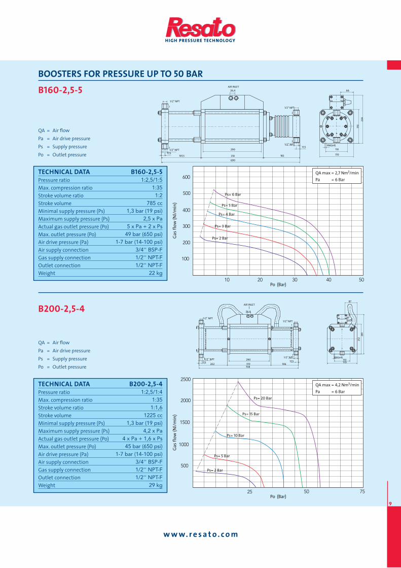
BOOSTERS FOR PRESSURE UP TO 50 BAR
B160-2,5-5
QA = Air fl ow
Pa = Air drive pressure
Ps = Supply pressure
Po = Outlet pressure
AIR INLET 26,4
1/2'' NPT
310 182 197,5
690
110 M6(x4)
170
66
170
239
290
1/2'' NPT
1/2'' NPT
1/2'' NPT
17,5
17,5
B200-2,5-4
QA = Air fl ow
Pa = Air drive pressure
Ps = Supply pressure
Po = Outlet pressure
Po (Bar)
Ga
s fl
ow
(N
l/m
in)
52 05
005
0001
0051
0002
0052
57
QA max = 4,2 Nm3/min
Pa = 6 Bar
Ps= 15 Bar
Ps= 20 Bar
Ps= 10 Bar
Ps= 5 Bar
Ps= 2 Bar
TECHNICAL DATA B160-2,5-5Pressure ratio
Max. compression ratio
Stroke volume ratio
Stroke volume
Minimal supply pressure (Ps)
Maximum supply pressure (Ps)
Actual gas outlet pressure (Po)
Max. outlet pressure (Po)
Air drive pressure (Pa)
Air supply connection
Gas supply connection
Outlet connection
Weight
1:2,5/1:51:351:2
785 cc1,3 bar (19 psi)
2,5 x Pa5 x Pa + 2 x Ps
49 bar (650 psi)1-7 bar (14-100 psi)
3/4'' BSP-F1/2'' NPT-F1/2'' NPT-F
22 kg
Po (Bar)
Ga
s fl
ow
(N
l/m
in)
0201
001
002
003
004
005
050403
006QA max = 2,7 Nm3/min
Pa = 6 Bar
Ps= 5 Bar
Ps= 6 Bar
Ps= 4 Bar
Ps= 3 Bar
Ps= 2 Bar
TECHNICAL DATA B200-2,5-4Pressure ratio
Max. compression ratio
Stroke volume ratio
Stroke volume
Minimal supply pressure (Ps)
Maximum supply pressure (Ps)
Actual gas outlet pressure (Po)
Max. outlet pressure (Po)
Air drive pressure (Pa)
Air supply connection
Gas supply connection
Outlet connection
Weight
1:2,5/1:41:351:1,6
1225 cc1,3 bar (19 psi)
4,2 x Pa4 x Pa + 1,6 x Ps45 bar (650 psi)
1-7 bar (14-100 psi)3/4'' BSP-F1/2'' NPT-F1/2'' NPT-F
29 kg
AIR INLET
26,4
1/2'' NPT
310 196 202 708
110 M6(x4)
170
87
212
281
290 1/2'' NPT
1/2'' NPT
1/2'' NPT
17,5 17,5

www. re sa to . com
10
BOOSTERS FOR PRESSURE UP TO 120 BAR
B200-8-2
QA = Air fl ow
Pa = Air drive pressure
Ps = Supply pressure
Po = Outlet pressure
B160-10-1
QA = Air fl ow
Pa = Air drive pressure
Ps = Supply pressure
Po = Outlet pressure
Po (Bar)
Ga
s fl
ow
(N
l/m
in)
02 06
001
002
003
004
005
006
04
QA max = 2,7 Nm3/min
Pa = 6 Bar
Ps= 30 Bar
Ps= 25 Bar
Ps= 20 Bar
Ps= 15 Bar
Ps= 10 Bar
TECHNICAL DATA B200-8-2Pressure ratio
Max. compression ratio
Stroke volume ratio
Stroke volume
Minimal supply pressure (Ps)
Maximum supply pressure (Ps)
Actual gas outlet pressure (Po)
Max. outlet pressure (Po)
Air drive pressure (Pa)
Air supply connection
Gas supply connection
Outlet connection
Weight
1:81:15
-770 cc
3,8 bar (55 psi)55 bar (795 psi)
8 x Pa + Ps55 bar (795 psi)
1-7 bar (14-100 psi)3/4'' BSP-F1/2'' NPT-F1/2'' NPT-F
29 kg
Po (Bar)
Ga
s fl
ow
(N
l/m
in)
01 05040302 0706
002
004
006
008
0021
0001
0041
0061
0081QA max = 4,2 Nm3/min
Pa = 6 Bar
Ps= 15 Bar
Ps= 20 Bar
Ps= 10 Bar
Ps= 8 Bar
Ps= 5 Bar
TECHNICAL DATA B160-10-1Pressure ratio
Max. compression ratio
Stroke volume ratio
Stroke volume
Minimal supply pressure (Ps)
Maximum supply pressure (Ps)
Actual gas outlet pressure (Po)
Max. outlet pressure (Po)
Air drive pressure (Pa)
Air supply connection
Gas supply connection
Outlet connection
Weight
1:101:15
-200 cc
4,8 bar (70 psi)70 bar (1015 psi)
10 x Pa70 bar (1015 psi)
1-7 bar (14-100 psi)3/4'' BSP-F1/2'' NPT-F1/2'' NPT-F
17,5 kg
110 M6
212
87
212
281
AIR INLET 3/4'' BSP
1/2'' NPT
1/2'' NPT 1/2'' NPT
1/2'' NPT
17,5 17,5 166 166
290 341 673
Outlet
Inlet
Outlet
Inlet
3/4'' BSP
1/2'' NPT
341 162
Outlet
Inlet
110 M6
170
66
170
239
290 1/2'' NPT
18 18
www. re sa to . com
11
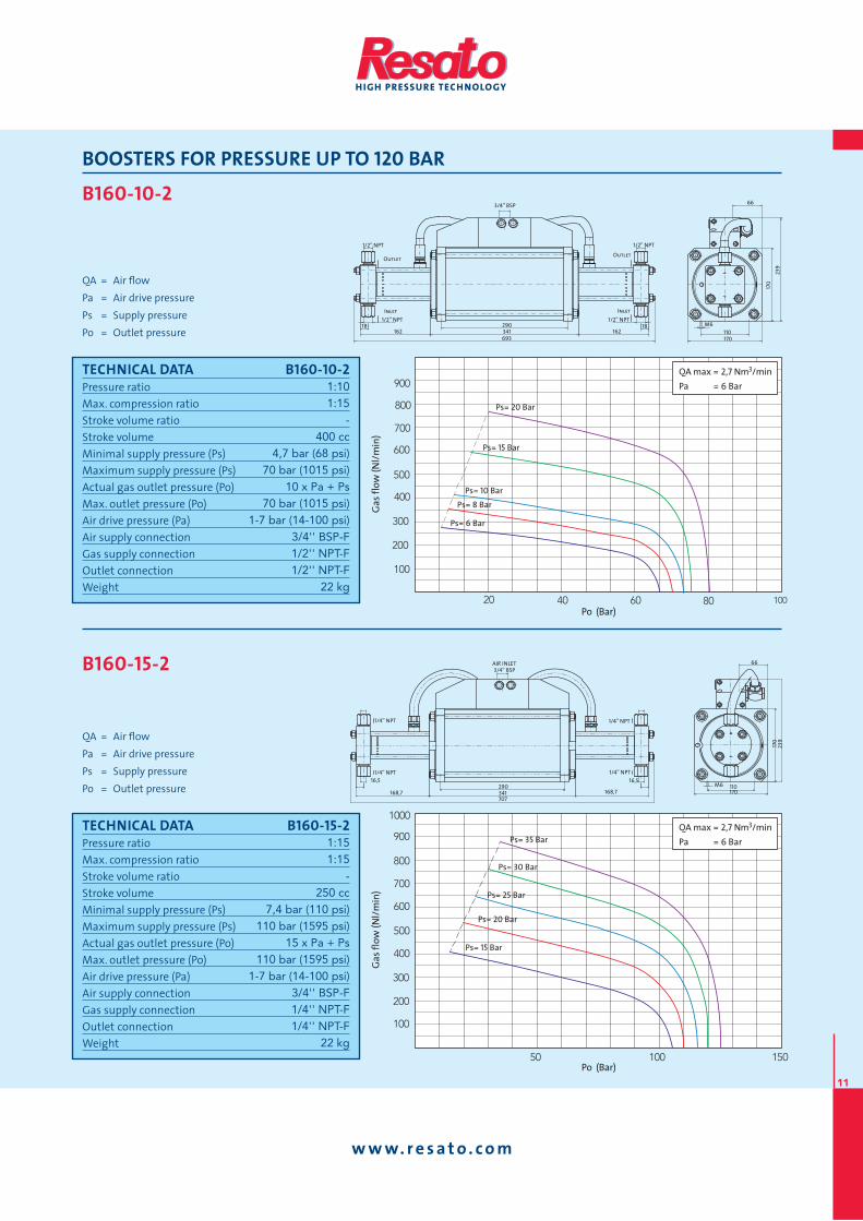
BOOSTERS FOR PRESSURE UP TO 120 BAR
B160-10-2
QA = Air fl ow
Pa = Air drive pressure
Ps = Supply pressure
Po = Outlet pressure
B160-15-2
QA = Air fl ow
Pa = Air drive pressure
Ps = Supply pressure
Po = Outlet pressure
Po (Bar)
Ga
s fl
ow
(N
l/m
in)
05100105
001
002
003
004
006
005
007
008
009
0001QA max = 2,7 Nm3/min
Pa = 6 BarPs= 35 Bar
Ps= 30 Bar
Ps= 25 Bar
Ps= 20 Bar
Ps= 15 Bar
110 M6 170
66
170
239
3/4'' BSP
1/4'' NPT
1/4'' NPT 1/4'' NPT
1/4'' NPT
16,5 16,5
168,7 168,7 290 341 707
AIR INLET
TECHNICAL DATA B160-10-2Pressure ratio
Max. compression ratio
Stroke volume ratio
Stroke volume
Minimal supply pressure (Ps)
Maximum supply pressure (Ps)
Actual gas outlet pressure (Po)
Max. outlet pressure (Po)
Air drive pressure (Pa)
Air supply connection
Gas supply connection
Outlet connection
Weight
1:101:15
-400 cc
4,7 bar (68 psi)70 bar (1015 psi)
10 x Pa + Ps70 bar (1015 psi)
1-7 bar (14-100 psi)3/4'' BSP-F1/2'' NPT-F1/2'' NPT-F
22 kg
Po (Bar)
Ga
s fl
ow
(N
l/m
in)
02 08 001
001
002
003
004
005
006
0604
007
008
009QA max = 2,7 Nm3/min
Pa = 6 Bar
Ps= 20 Bar
Ps= 15 Bar
Ps= 10 Bar
Ps= 8 Bar
Ps= 6 Bar
TECHNICAL DATA B160-15-2Pressure ratio
Max. compression ratio
Stroke volume ratio
Stroke volume
Minimal supply pressure (Ps)
Maximum supply pressure (Ps)
Actual gas outlet pressure (Po)
Max. outlet pressure (Po)
Air drive pressure (Pa)
Air supply connection
Gas supply connection
Outlet connection
Weight
1:151:15
-250 cc
7,4 bar (110 psi)110 bar (1595 psi)
15 x Pa + Ps110 bar (1595 psi)
1-7 bar (14-100 psi)3/4'' BSP-F1/4'' NPT-F1/4'' NPT-F
22 kg
3/4'' BSP
1/2'' NPT
Outlet Outlet
Inlet Inlet 1/2'' NPT 1/2'' NPT
1/2'' NPT
18 18 162 162
290 341 693
110 M6
170
66
170
239
www. re sa to . com
12
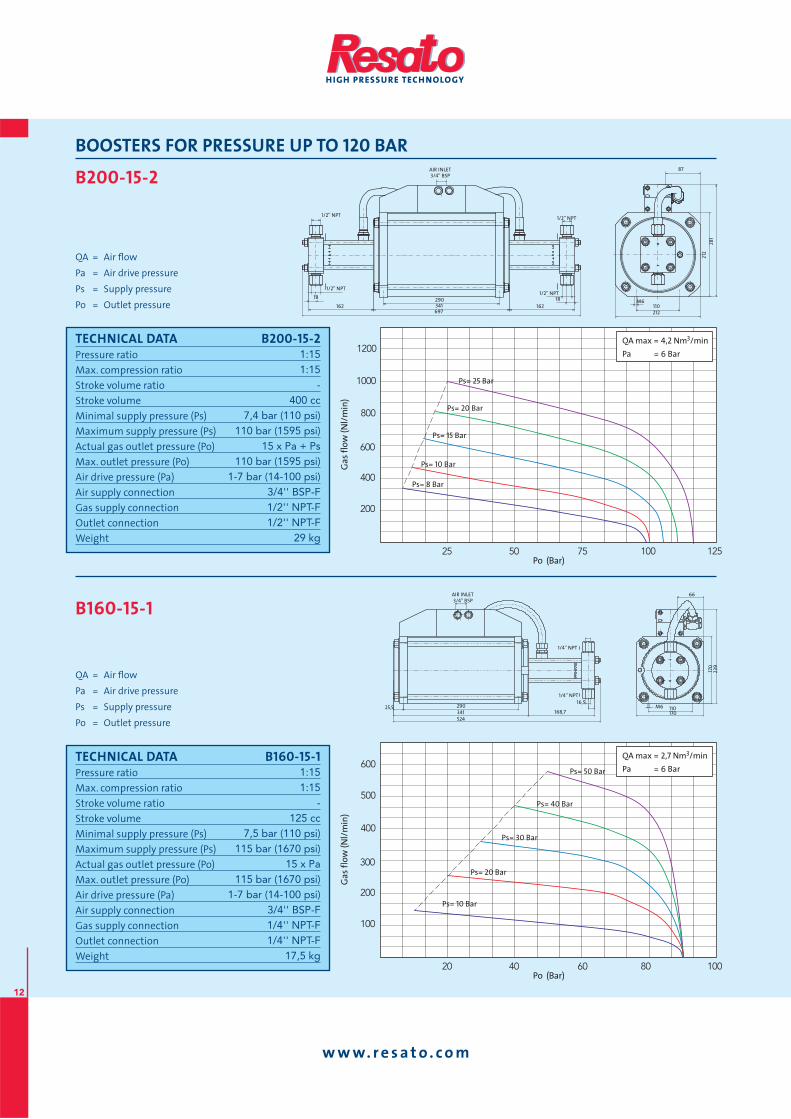
BOOSTERS FOR PRESSURE UP TO 120 BAR
B200-15-2
QA = Air fl ow
Pa = Air drive pressure
Ps = Supply pressure
Po = Outlet pressure
B160-15-1
QA = Air fl ow
Pa = Air drive pressure
Ps = Supply pressure
Po = Outlet pressure
Po (Bar)
Ga
s fl
ow
(N
l/m
in)
02 00108
001
002
003
004
005
006
0604
QA max = 2,7 Nm3/min
Pa = 6 BarPs= 50 Bar
Ps= 40 Bar
Ps= 30 Bar
Ps= 20 Bar
Ps= 10 Bar
TECHNICAL DATA B200-15-2Pressure ratio
Max. compression ratio
Stroke volume ratio
Stroke volume
Minimal supply pressure (Ps)
Maximum supply pressure (Ps)
Actual gas outlet pressure (Po)
Max. outlet pressure (Po)
Air drive pressure (Pa)
Air supply connection
Gas supply connection
Outlet connection
Weight
1:151:15
-400 cc
7,4 bar (110 psi)110 bar (1595 psi)
15 x Pa + Ps110 bar (1595 psi)
1-7 bar (14-100 psi)3/4'' BSP-F1/2'' NPT-F1/2'' NPT-F
29 kg
Po (Bar)
Ga
s fl
ow
(N
l/m
in)
52 521001
002
004
006
008
0001
0021
5705
QA max = 4,2 Nm3/min
Pa = 6 Bar
Ps= 20 Bar
Ps= 25 Bar
Ps= 15 Bar
Ps= 10 Bar
Ps= 8 Bar
TECHNICAL DATA B160-15-1Pressure ratio
Max. compression ratio
Stroke volume ratio
Stroke volume
Minimal supply pressure (Ps)
Maximum supply pressure (Ps)
Actual gas outlet pressure (Po)
Max. outlet pressure (Po)
Air drive pressure (Pa)
Air supply connection
Gas supply connection
Outlet connection
Weight
1:151:15
-125 cc
7,5 bar (110 psi)115 bar (1670 psi)
15 x Pa115 bar (1670 psi)
1-7 bar (14-100 psi)3/4'' BSP-F1/4'' NPT-F1/4'' NPT-F
17,5 kg
110 M6
212
87
212
281
AIR INLET 3/4'' BSP
1/2'' NPT
1/2'' NPT 1/2'' NPT
1/2'' NPT
18 18
162 162 290 341 697
3/4'' BSP
1/4'' NPT
168,7 524 341
110 M6 170
66
170
239
290
1/4'' NPT 16,5
25,5
AIR INLET
www. re sa to . com
13
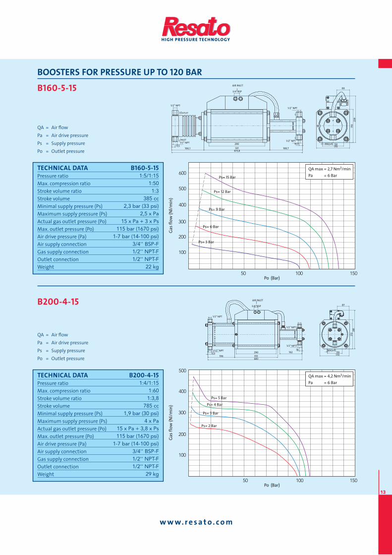
BOOSTERS FOR PRESSURE UP TO 120 BAR
B160-5-15
QA = Air fl ow
Pa = Air drive pressure
Ps = Supply pressure
Po = Outlet pressure
AIR INLET
3/4’’BSP
1/2'' NPT
341 168,7 166,1 675,8
110 M6(x4)170
66
170
239
290 1/2'' NPT
1/2'' NPT Inlet
1/2'' NPT
Outlet
16,5 17,5
B200-4-15
QA = Air fl ow
Pa = Air drive pressure
Ps = Supply pressure
Po = Outlet pressure
Po (Bar)
Ga
s fl
ow
(N
l/m
in)
05 001
QA max = 4,2 Nm3/min
Pa = 6 Bar
001
002
003
004
005
051
QA max = 4,2 Nm3/min
Pa = 6 Bar
Ps= 5 Bar
Ps= 4 Bar
Ps= 3 Bar
Ps= 2 Bar
110 M6(x4)
170
87
212
281
TECHNICAL DATA B160-5-15Pressure ratio
Max. compression ratio
Stroke volume ratio
Stroke volume
Minimal supply pressure (Ps)
Maximum supply pressure (Ps)
Actual gas outlet pressure (Po)
Max. outlet pressure (Po)
Air drive pressure (Pa)
Air supply connection
Gas supply connection
Outlet connection
Weight
1:5/1:151:501:3
385 cc2,3 bar (33 psi)
2,5 x Pa15 x Pa + 3 x Ps
115 bar (1670 psi)1-7 bar (14-100 psi)
3/4'' BSP-F1/2'' NPT-F1/2'' NPT-F
22 kg
Po (Bar)
Ga
s fl
ow
(N
l/m
in)
001 05105
001
002
003
004
005
006QA max = 2,7 Nm3/min
Pa = 6 Bar
Ps= 12 Bar
Ps= 15 Bar
Ps= 9 Bar
Ps= 6 Bar
Ps= 3 Bar
TECHNICAL DATA B200-4-15Pressure ratio
Max. compression ratio
Stroke volume ratio
Stroke volume
Minimal supply pressure (Ps)
Maximum supply pressure (Ps)
Actual gas outlet pressure (Po)
Max. outlet pressure (Po)
Air drive pressure (Pa)
Air supply connection
Gas supply connection
Outlet connection
Weight
1:4/1:151:601:3,8
785 cc1,9 bar (30 psi)
4 x Pa15 x Pa + 3,8 x Ps115 bar (1670 psi)
1-7 bar (14-100 psi)3/4'' BSP-F1/2'' NPT-F1/2'' NPT-F
29 kg
AIR INLET
3/4’’BSP
1/2'' NPT
310 162
196 683
290
1/2'' NPT
1/2'' NPT
1/2'' NPT
18 17,5

www. re sa to . com
14
BOOSTERS FOR PRESSURE UP TO 250 BAR
B200-25-2
QA = Air fl ow
Pa = Air drive pressure
Ps = Supply pressure
Po = Outlet pressure
B160-30-1
QA = Air fl ow
Pa = Air drive pressure
Ps = Supply pressure
Po = Outlet pressure
Po (Bar)
Ga
s fl
ow
(N
l/m
in)
05100105
001
002
003
004
005
052002
QA max = 2,7 Nm3/min
Pa = 6 Bar
Ps= 60 Bar
Ps= 70 Bar
Ps= 50 Bar
Ps= 40 Bar
Ps= 30 Bar
TECHNICAL DATA B200-25-2Pressure ratio
Max. compression ratio
Stroke volume ratio
Stroke volume
Minimal supply pressure (Ps)
Maximum supply pressure (Ps)
Actual gas outlet pressure (Po)
Max. outlet pressure (Po)
Air drive pressure (Pa)
Air supply connection
Gas supply connection
Outlet connection
Weight
1:251:15
-250 cc
11,6 bar (170 psi)175 bar (2540 psi)
25 x Pa + Ps175 bar (2540 psi)
1-7 bar (14-100 psi)3/4'' BSP-F1/4'' NPT-F1/4'' NPT-F
29 kg
Po (Bar)
Ga
s fl
ow
(N
l/m
in)
021 08106 0120510903
001
002
003
004
005
006
007
008
009
0001 QA max = 4,2 Nm3/min
Pa = 6 Bar
Ps= 30 Bar
Ps= 35 Bar
Ps= 25 Bar
Ps= 20 Bar
Ps= 15 Bar
TECHNICAL DATA B160-30-1Pressure ratio
Max. compression ratio
Stroke volume ratio
Stroke volume
Minimal supply pressure (Ps)
Maximum supply pressure (Ps)
Actual gas outlet pressure (Po)
Max. outlet pressure (Po)
Air drive pressure (Pa)
Air supply connection
Gas supply connection
Outlet connection
Weight
1:301:15
-70 cc
13,3 bar (190 psi)210 bar (3050 psi)
30 x Pa210 bar (3050 psi)
1-7 bar (14-100 psi)3/4'' BSP-F1/4'' NPT-F1/4'' NPT-F
17,5 kg
110 M6
212
87
212
281
AIR INLET
3/4'' BSP
1/4'' NPT
1/4'' NPT
1/4'' NPT
1/4'' NPT 16,5
169 16,5
169 290 341 711
110170
66
170
239
AIR INLET3/4'' BSP
1/4'' NPT
523 168290 1/4'' NPT
16,525,5

www. re sa to . com
15
BOOSTERS FOR PRESSURE UP TO 250 BAR
B160-30-2
QA = Air fl ow
Pa = Air drive pressure
Ps = Supply pressure
Po = Outlet pressure
B160-5-30
QA = Air fl ow
Pa = Air drive pressure
Ps = Supply pressure
Po = Outlet pressure
Po (Bar)
Ga
s fl
ow
(N
l/m
in)
05
001
051
002
052
003
003002001
QA max = 2,7 Nm3/min
Pa = 6 Bar
Ps= 5 Bar
Ps= 6 Bar
Ps= 4 Bar
Ps= 3 Bar
Ps= 2 Bar
TECHNICAL DATA B160-30-2Pressure ratio
Max. compression ratio
Stroke volume ratio
Stroke volume
Minimal supply pressure (Ps)
Maximum supply pressure (Ps)
Actual gas outlet pressure (Po)
Max. outlet pressure (Po)
Air drive pressure (Pa)
Air supply connection
Gas supply connection
Outlet connection
Weight
1:301:15
-140 cc
13,2 bar (190 psi)210 bar (3050 psi)
30 x Pa + Ps210 bar (3050 psi)
1-7 bar (14-100 psi)3/4'' BSP-F1/4'' NPT-F1/4'' NPT-F
22 kg
Po (Bar)
Ga
s fl
ow
(N
l/m
in)
003002001
001
002
003
004
006
005
007
008
009
0001
Ps= 60 Bar
Ps= 50 Bar
Ps= 40 Bar
Ps= 30 Bar
Ps= 20 Bar
QA max = 2,7 Nm3/min
Pa = 6 Bar
TECHNICAL DATA B160-5-30Pressure ratio
Max. compression ratio
Stroke volume ratio
Stroke volume
Minimal supply pressure (Ps)
Maximum supply pressure (Ps)
Actual gas outlet pressure (Po)
Max. outlet pressure (Po)
Air drive pressure (Pa)
Air supply connection
Gas supply connection
Outlet connection
Weight
1:5/1:301:100
1:6385 cc
2,0 bar (30 psi)1 x Pa
30 x Pa + 6 x Ps210 bar (3050 psi)
1-7 bar (14-100 psi)3/4'' BSP-F1/2'' NPT-F1/4'' NPT-F
22 kg
110170
66
170
239
AIR INLET3/4'' BSP
1/4'' NPT
1/4'' NPT1/4'' NPT
1/4'' NPT
16,516,5 168168
290
341
709
AIR INLET
26,4
1/4'' NPT
341 168 166
Inlet
675
290 1/4'' NPT 1/2'' NPT
1/2'' NPT
Outlet
16,5 17,5 110 M6(x4)
170
66
170
239
www. re sa to . com
16
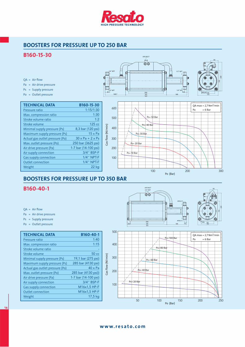
BOOSTERS FOR PRESSURE UP TO 250 BAR
B160-15-30
QA = Air fl ow
Pa = Air drive pressure
Ps = Supply pressure
Po = Outlet pressure110 M6(x4)170
66
170
239
B160-40-1
QA = Air fl ow
Pa = Air drive pressure
Ps = Supply pressure
Po = Outlet pressure
Po (Bar)
Ga
s fl
ow
(N
l/m
in)
05100105
001
002
003
004
005
052002
QA max = 2,7 Nm3/min
Pa = 6 Bar
Ps= 80 Bar
Ps= 100 Bar
Ps= 60 Bar
Ps= 40 Bar
Ps= 20 Bar
TECHNICAL DATA B160-15-30Pressure ratio
Max. compression ratio
Stroke volume ratio
Stroke volume
Minimal supply pressure (Ps)
Maximum supply pressure (Ps)
Actual gas outlet pressure (Po)
Max. outlet pressure (Po)
Air drive pressure (Pa)
Air supply connection
Gas supply connection
Outlet connection
Weight
1:15/1:301:301:2
125 cc8,3 bar (120 psi)
15 x Pa30 x Pa + 2 x Ps
250 bar (3625 psi)1-7 bar (14-100 psi)
3/4'' BSP-F1/4'' NPT-F1/4'' NPT-F
22 kg
Po (Bar)
Ga
s fl
ow
(N
l/m
in)
003002001
001
002
003
004
005
006QA max = 2,7 Nm3/min
Pa = 6 Bar
Ps= 40 Bar
Ps= 50 Bar
Ps= 30 Bar
Ps= 20 Bar
Ps= 10 Bar
TECHNICAL DATA B160-40-1Pressure ratio
Max. compression ratio
Stroke volume ratio
Stroke volume
Minimal supply pressure (Ps)
Maximum supply pressure (Ps)
Actual gas outlet pressure (Po)
Max. outlet pressure (Po)
Air drive pressure (Pa)
Air supply connection
Gas supply connection
Outlet connection
Weight
1:401:15
-50 cc
19,1 bar (275 psi)285 bar (4130 psi)
40 x Pa285 bar (4130 psi))
1-7 bar (14-100 psi)3/4'' BSP-F
M16x1,5 HP-FM16x1,5 HP-F
17,5 kg
BOOSTERS FOR PRESSURE UP TO 350 BAR
110 M6 170
66
170
239
AIR INLET
26,4
1/2'' NPT
341 168 168,7 707
290 1/4'' NPT 1/4'' NPT
1/4'' NPT
16,5 16,5
AIR INLET 3/4'' BSP
341 525
168 290
M16x1.5
M16x1.5
17,5 25,5
www. re sa to . com
17
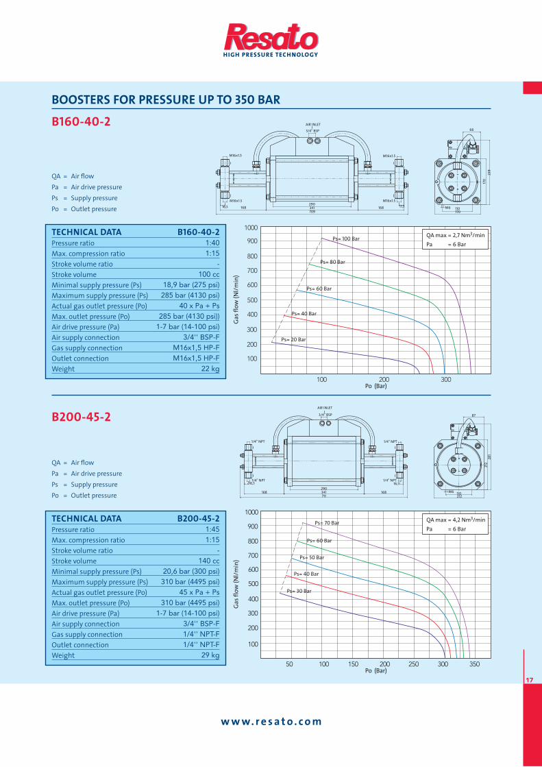
BOOSTERS FOR PRESSURE UP TO 350 BAR
B160-40-2
QA = Air fl ow
Pa = Air drive pressure
Ps = Supply pressure
Po = Outlet pressure
B200-45-2
QA = Air fl ow
Pa = Air drive pressure
Ps = Supply pressure
Po = Outlet pressure
Po (Bar)
Ga
s fl
ow
(N
l/m
in)
05 053003052002051001
001
002
003
004
005
006
007
008
009
0001 QA max = 4,2 Nm3/min
Pa = 6 Bar
Ps= 60 Bar
Ps= 70 Bar
Ps= 50 Bar
Ps= 40 Bar
Ps= 30 Bar
110 M6 212
87
212
281
AIR INLET
3/4'' BSP
1/4'' NPT
1/4'' NPT 1/4'' NPT
1/4'' NPT
16,5 16,5
168 168 290 341 711
TECHNICAL DATA B160-40-2Pressure ratio
Max. compression ratio
Stroke volume ratio
Stroke volume
Minimal supply pressure (Ps)
Maximum supply pressure (Ps)
Actual gas outlet pressure (Po)
Max. outlet pressure (Po)
Air drive pressure (Pa)
Air supply connection
Gas supply connection
Outlet connection
Weight
1:401:15
-100 cc
18,9 bar (275 psi)285 bar (4130 psi)
40 x Pa + Ps285 bar (4130 psi))
1-7 bar (14-100 psi)3/4'' BSP-F
M16x1,5 HP-FM16x1,5 HP-F
22 kg
Po (Bar)
Ga
s fl
ow
(N
l/m
in)
003002001
001
002
003
004
006
005
007
008
009
0001QA max = 2,7 Nm3/min
Pa = 6 BarPs= 100 Bar
Ps= 80 Bar
Ps= 60 Bar
Ps= 40 Bar
Ps= 20 Bar
TECHNICAL DATA B200-45-2Pressure ratio
Max. compression ratio
Stroke volume ratio
Stroke volume
Minimal supply pressure (Ps)
Maximum supply pressure (Ps)
Actual gas outlet pressure (Po)
Max. outlet pressure (Po)
Air drive pressure (Pa)
Air supply connection
Gas supply connection
Outlet connection
Weight
1:451:15
-140 cc
20,6 bar (300 psi)310 bar (4495 psi)
45 x Pa + Ps310 bar (4495 psi)
1-7 bar (14-100 psi)3/4'' BSP-F1/4'' NPT-F1/4'' NPT-F
29 kg
110 M6 170
66
170
239
AIR INLET
3/4'' BSP
M16x1.5
M16x1.5
M16x1.5
M16x1.5
17,5 16,5 168 168 290 341 709
www. re sa to . com
18
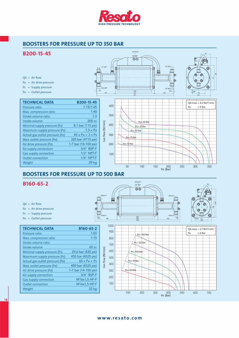
BOOSTERS FOR PRESSURE UP TO 350 BAR
B200-15-45
QA = Air fl ow
Pa = Air drive pressure
Ps = Supply pressure
Po = Outlet pressure
AIR INLET
3/4’’BSP
1/4'' NPT
1/4'' NPT
341 168 162 671
110 M6
212
87
212
281
290
1/2'' NPT
1/2'' NPT
16,5 18
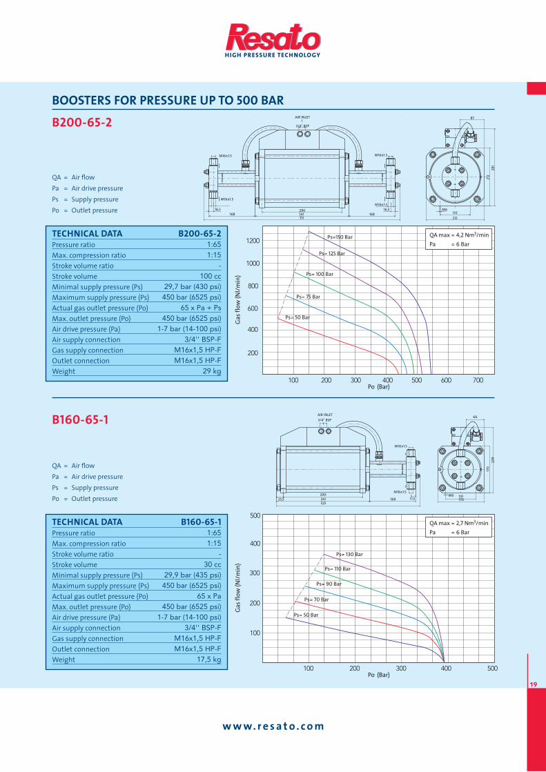
B160-65-2
QA = Air fl ow
Pa = Air drive pressure
Ps = Supply pressure
Po = Outlet pressure
Po (Bar)
Ga
s fl
ow
(N
l/m
in)
005004003002001
001
002
003
004
006
006 007
005
007
008
009
0001
Ps= 150 Bar
Ps= 125 Bar
Ps= 100 Bar
Ps= 75 Bar
Ps= 50 Bar
QA max = 2,7 Nm3/min
Pa = 6 Bar
TECHNICAL DATA B200-15-45Pressure ratio
Max. compression ratio
Stroke volume ratio
Stroke volume
Minimal supply pressure (Ps)
Maximum supply pressure (Ps)
Actual gas outlet pressure (Po)
Max. outlet pressure (Po)
Air drive pressure (Pa)
Air supply connection
Gas supply connection
Outlet connection
Weight
1:15/1:451:401:3
200 cc8,1 bar (115 psi)
7,5 x Pa45 x Pa + 3 x Ps
325 bar (4715 psi)1-7 bar (14-100 psi)
3/4'' BSP-F1/2'' NPT-F1/4'' NPT-F
29 kg
Po (Bar)
Ga
s fl
ow
(N
l/m
in)
05200205100105 053003
001
002
003
004
005
006QA max = 4,2 Nm3/min
Pa = 6 Bar
QA max = 4,2 Nm3/min
Pa = 6 Bar
Ps= 25 Bar
Ps= 30 Bar
Ps= 20 Bar
Ps= 15 Bar
Ps= 10 Bar
TECHNICAL DATA B160-65-2Pressure ratio
Max. compression ratio
Stroke volume ratio
Stroke volume
Minimal supply pressure (Ps)
Maximum supply pressure (Ps)
Actual gas outlet pressure (Po)
Max. outlet pressure (Po)
Air drive pressure (Pa)
Air supply connection
Gas supply connection
Outlet connection
Weight
1:651:15
-60 cc
29,6 bar (430 psi)450 bar (6525 psi)
65 x Pa + Ps450 bar (6525 psi)
1-7 bar (14-100 psi)3/4'' BSP-F
M16x1,5 HP-FM16x1,5 HP-F
22 kg
BOOSTERS FOR PRESSURE UP TO 500 BAR
110 M6 170
66
170
239
AIR INLET
3/4'' BSP
M16x1.5
M16x1.5
M16x1.5
M16x1.5
17,5 16,5 168 168 290 341 709
www. re sa to . com
19
BOOSTERS FOR PRESSURE UP TO 500 BAR
B200-65-2
QA = Air fl ow
Pa = Air drive pressure
Ps = Supply pressure
Po = Outlet pressure
B160-65-1
QA = Air fl ow
Pa = Air drive pressure
Ps = Supply pressure
Po = Outlet pressure
Po (Bar)
Ga
s fl
ow
(N
l/m
in)
003002001
001
002
003
004
005
005004
QA max = 2,7 Nm3/min
Pa = 6 Bar
Ps= 110 Bar
Ps= 130 Bar
Ps= 90 Bar
Ps= 70 Bar
Ps= 50 Bar
TECHNICAL DATA B200-65-2Pressure ratio
Max. compression ratio
Stroke volume ratio
Stroke volume
Minimal supply pressure (Ps)
Maximum supply pressure (Ps)
Actual gas outlet pressure (Po)
Max. outlet pressure (Po)
Air drive pressure (Pa)
Air supply connection
Gas supply connection
Outlet connection
Weight
1:651:15
-100 cc
29,7 bar (430 psi)450 bar (6525 psi)
65 x Pa + Ps450 bar (6525 psi)
1-7 bar (14-100 psi)3/4'' BSP-F
M16x1,5 HP-FM16x1,5 HP-F
29 kg
Po (Bar)
Ga
s fl
ow
(N
l/m
in)
001
002
004
006
008
0001
0021
007006005004003002
QA max = 4,2 Nm3/min
Pa = 6 Bar
Ps= 125 Bar
Ps=150 Bar
Ps= 100 Bar
Ps= 75 Bar
Ps= 50 Bar
TECHNICAL DATA B160-65-1Pressure ratio
Max. compression ratio
Stroke volume ratio
Stroke volume
Minimal supply pressure (Ps)
Maximum supply pressure (Ps)
Actual gas outlet pressure (Po)
Max. outlet pressure (Po)
Air drive pressure (Pa)
Air supply connection
Gas supply connection
Outlet connection
Weight
1:651:15
-30 cc
29,9 bar (435 psi)450 bar (6525 psi)
65 x Pa450 bar (6525 psi)
1-7 bar (14-100 psi)3/4'' BSP-F
M16x1,5 HP-FM16x1,5 HP-F
17,5 kg
110 M6
212
87
212
281
AIR INLET
3/4'' BSP
M16x1.5
M16x1.5
M16x1.5
M16x1.5
16,5 16,5 168 168
290 341 711
AIR INLET 3/4'' BSP
341 525
168 110 M6 170
66
170
239
290 M16x1.5
M16x1.5
17,5 25,5

www. re sa to . com
20
BOOSTERS FOR PRESSURE UP TO 500 BAR
B160-15-65
QA = Air fl ow
Pa = Air drive pressure
Ps = Supply pressure
Po = Outlet pressure
AIR INLET
26,4
M16x1.5
M16x1.5
341 168 168,7 707
110 M6(x4)
170
66
170
239
290 1/4'' NPT
1/4'' NPT
16,5 16,5
B200-15-65
QA = Air fl ow
Pa = Air drive pressure
Ps = Supply pressure
Po = Outlet pressure
Po (Bar)
Ga
s fl
ow
(N
l/m
in)
005004003002001 007006
001
002
003
004
005QA max = 4,2 Nm3/min
Pa = 6 Bar
QA max = 4,2 Nm3/min
Pa = 6 Bar
Ps= 25 Bar
Ps= 20 Bar
Ps= 15 Bar
Ps= 10 Bar
AIR INLET
3/4’’BSP
1/4'' NPT
341 168 162 671
110 M6
212
87
212
281
290
1/4'' NPT 1/2'' NPT
1/2'' NPT
16,5 18
TECHNICAL DATA B160-15-65Pressure ratio
Max. compression ratio
Stroke volume ratio
Stroke volume
Minimal supply pressure (Ps)
Maximum supply pressure (Ps)
Actual gas outlet pressure (Po)
Max. outlet pressure (Po)
Air drive pressure (Pa)
Air supply connection
Gas supply connection
Outlet connection
Weight
1:15/1:651:601:4
125 cc7,5 bar (110 psi)
4,5 x Pa65 x Pa + 4 x Ps
450 bar (6525 psi)1-7 bar (14-100 psi)
3/4'' BSP-F1/4'' NPT-F
M16x1,5 HP-F22 kg
Po (Bar)
Ga
s fl
ow
(N
l/m
in)
57 051 522 003 573
05
001
051
002
052
003
054 525
QA max = 2,7 Nm3/min
Pa = 6 Bar
Ps= 20 Bar
Ps= 25 Bar
Ps= 15 Bar
Ps= 10 Bar
Ps= 8 Bar
TECHNICAL DATA B200-15-65Pressure ratio
Max. compression ratio
Stroke volume ratio
Stroke volume
Minimal supply pressure (Ps)
Maximum supply pressure (Ps)
Actual gas outlet pressure (Po)
Max. outlet pressure (Po)
Air drive pressure (Pa)
Air supply connection
Gas supply connection
Outlet connection
Weight
1:15/1:651:551:4,3
200 cc8,2 bar (120 psi)
4,5 x Pa65 x Pa + 4,3 x Ps450 bar (6525 psi)
1-7 bar (14-100 psi)3/4'' BSP-F1/2'' NPT-F
M16x1,5 HP-F29 kg
www. re sa to . com
21
BOOSTERS FOR PRESSURE UP TO 500 BAR
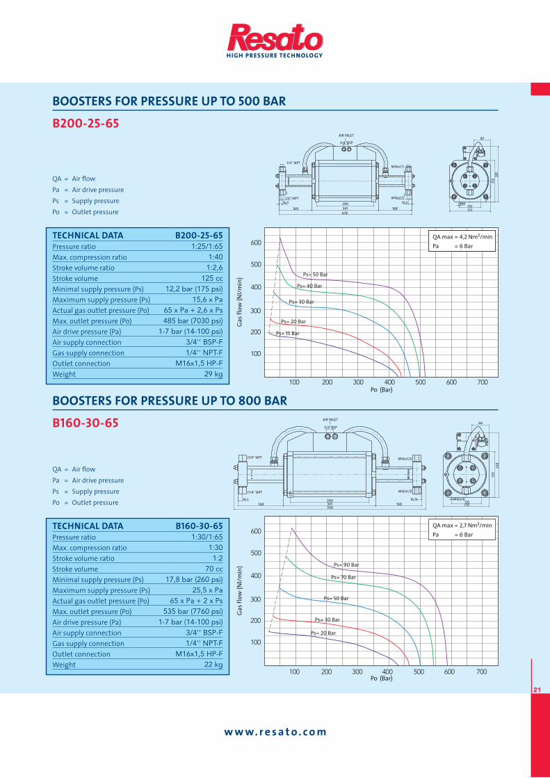
B200-25-65
QA = Air fl ow
Pa = Air drive pressure
Ps = Supply pressure
Po = Outlet pressure
AIR INLET
3/4’’BSP
341 168 169 678
110 M6
212
87
212
281
290
M16x1.5
M16x1.5 1/4'' NPT
1/4'' NPT 16,5 16,5
B160-30-65
QA = Air fl ow
Pa = Air drive pressure
Ps = Supply pressure
Po = Outlet pressure
Po (Bar)
Ga
s fl
ow
(N
l/m
in)
001
002
003
004
005
006
007006005004003002001
Ps= 70 Bar
Ps= 90 Bar
Ps= 50 Bar
Ps= 30 Bar
Ps= 20 Bar
QA max = 2,7 Nm3/min
Pa = 6 Bar
TECHNICAL DATA B200-25-65Pressure ratio
Max. compression ratio
Stroke volume ratio
Stroke volume
Minimal supply pressure (Ps)
Maximum supply pressure (Ps)
Actual gas outlet pressure (Po)
Max. outlet pressure (Po)
Air drive pressure (Pa)
Air supply connection
Gas supply connection
Outlet connection
Weight
1:25/1:651:401:2,6
125 cc12,2 bar (175 psi)
15,6 x Pa65 x Pa + 2,6 x Ps485 bar (7030 psi)
1-7 bar (14-100 psi)3/4'' BSP-F1/4'' NPT-F
M16x1,5 HP-F29 kg
Po (Bar)
Ga
s fl
ow
(N
l/m
in)
001
002
003
004
005
006
003 006004002 007001 005
QA max = 4,2 Nm3/min
Pa = 6 Bar
QA max = 4,2 Nm3/min
Pa = 6 Bar
Ps= 40 Bar
Ps= 50 Bar
Ps= 30 Bar
Ps= 20 Bar
Ps= 15 Bar
TECHNICAL DATA B160-30-65Pressure ratio
Max. compression ratio
Stroke volume ratio
Stroke volume
Minimal supply pressure (Ps)
Maximum supply pressure (Ps)
Actual gas outlet pressure (Po)
Max. outlet pressure (Po)
Air drive pressure (Pa)
Air supply connection
Gas supply connection
Outlet connection
Weight
1:30/1:651:301:2
70 cc17,8 bar (260 psi)
25,5 x Pa65 x Pa + 2 x Ps
535 bar (7760 psi)1-7 bar (14-100 psi)
3/4'' BSP-F1/4'' NPT-F
M16x1,5 HP-F22 kg
BOOSTERS FOR PRESSURE UP TO 800 BAR AIR INLET
3/4”BSP
M16x1,5
M16x1,5
341 168 168 709
110 M6(x4)
170
66
170
239
290
1/4'' NPT
1/4'' NPT
16,5 16,5
www. re sa to . com
22
BOOSTERS FOR PRESSURE UP TO 800 BAR
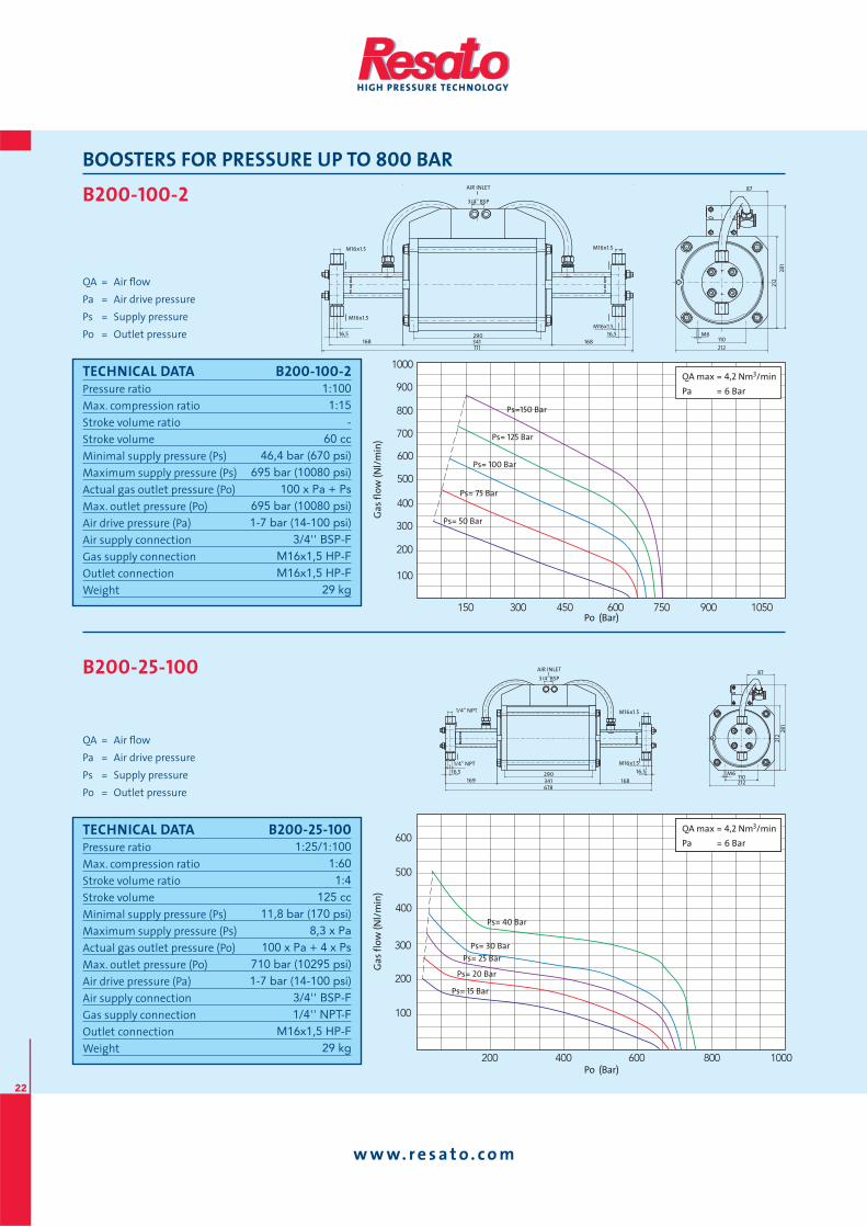
B200-100-2
QA = Air fl ow
Pa = Air drive pressure
Ps = Supply pressure
Po = Outlet pressure
B200-25-100
QA = Air fl ow
Pa = Air drive pressure
Ps = Supply pressure
Po = Outlet pressure
Po (Bar)
Ga
s fl
ow
(N
l/m
in)
001
002
003
004
005
006
0001008006004002
QA max = 4,2 Nm3/min
Pa = 6 Bar
QA max = 4,2 Nm3/min
Pa = 6 Bar
Ps= 30 Bar
Ps= 40 Bar
Ps= 25 Bar
Ps= 20 Bar
Ps= 15 Bar
TECHNICAL DATA B200-100-2Pressure ratio
Max. compression ratio
Stroke volume ratio
Stroke volume
Minimal supply pressure (Ps)
Maximum supply pressure (Ps)
Actual gas outlet pressure (Po)
Max. outlet pressure (Po)
Air drive pressure (Pa)
Air supply connection
Gas supply connection
Outlet connection
Weight
1:1001:15
-60 cc
46,4 bar (670 psi)695 bar (10080 psi)
100 x Pa + Ps695 bar (10080 psi)1-7 bar (14-100 psi)
3/4'' BSP-FM16x1,5 HP-FM16x1,5 HP-F
29 kg
Po (Bar)
Ga
s fl
ow
(N
l/m
in)
051 0501009057006054003
001
002
003
004
005
006
007
008
009
0001 QA max = 4,2 Nm3/min
Pa = 6 Bar
Ps= 125 Bar
Ps=150 Bar
Ps= 100 Bar
Ps= 75 Bar
Ps= 50 Bar
TECHNICAL DATA B200-25-100Pressure ratio
Max. compression ratio
Stroke volume ratio
Stroke volume
Minimal supply pressure (Ps)
Maximum supply pressure (Ps)
Actual gas outlet pressure (Po)
Max. outlet pressure (Po)
Air drive pressure (Pa)
Air supply connection
Gas supply connection
Outlet connection
Weight
1:25/1:1001:601:4
125 cc11,8 bar (170 psi)
8,3 x Pa100 x Pa + 4 x Ps
710 bar (10295 psi)1-7 bar (14-100 psi)
3/4'' BSP-F1/4'' NPT-F
M16x1,5 HP-F29 kg
110 M6
212
87
212
281
AIR INLET
3/4'' BSP
M16x1.5
M16x1.5
M16x1.5
M16x1.5
16,5 16,5 168 168
290 341 711
AIR INLET 3/4’’BSP
M16x1.5
M16x1.5
341 168 169 678
110 M6
212
87
212
281
290
1/4'' NPT
1/4'' NPT
16,5 16,5
www. re sa to . com
23
BOOSTERS FOR PRESSURE UP TO 800 BAR
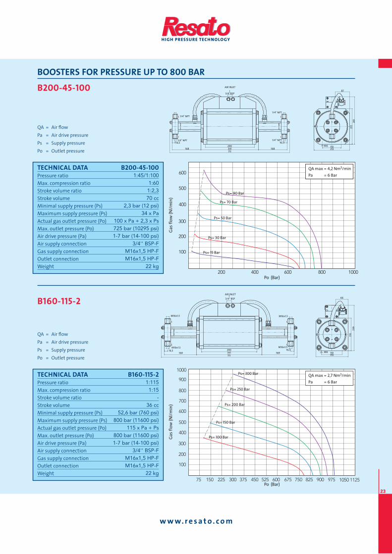
B200-45-100
QA = Air fl ow
Pa = Air drive pressure
Ps = Supply pressure
Po = Outlet pressure
AIR INLET
3/4’’BSP
1/4'' NPT
341 168 168 711
110 M6 212
87
212
281
290
1/4'' NPT 1/4'' NPT
1/4'' NPT
16,5 16,5
B160-115-2
QA = Air fl ow
Pa = Air drive pressure
Ps = Supply pressure
Po = Outlet pressure
Po (Bar)
Ga
s fl
ow
(N
l/m
in)
57 057576006525054573003522051 009528 579 52110501
001
002
003
004
006
005
007
008
009
0001QA max = 2,7 Nm3/min
Pa = 6 Bar
Ps= 300 Bar
Ps= 250 Bar
Ps= 200 Bar
Ps= 150 Bar
Ps= 100 Bar
110 M6 170
66
170
239
AIR INLET
3/4'' BSP
M16x1.5
M16x1.5
M16x1.5
M16x1.5
16,5 16,5 169 169
290 341 711
TECHNICAL DATA B200-45-100Pressure ratio
Max. compression ratio
Stroke volume ratio
Stroke volume
Minimal supply pressure (Ps)
Maximum supply pressure (Ps)
Actual gas outlet pressure (Po)
Max. outlet pressure (Po)
Air drive pressure (Pa)
Air supply connection
Gas supply connection
Outlet connection
Weight
1:45/1:1001:601:2,370 cc
2,3 bar (12 psi)34 x Pa
100 x Pa + 2,3 x Ps725 bar (10295 psi)1-7 bar (14-100 psi)
3/4'' BSP-FM16x1,5 HP-FM16x1,5 HP-F
22 kg
Po (Bar)
Ga
s fl
ow
(N
l/m
in)
001
002
003
004
005
006
0001008006004002
Ps= 70 Bar
Ps= 90 Bar
Ps= 50 Bar
Ps= 30 Bar
Ps= 15 Bar
QA max = 4,2 Nm3/min
Pa = 6 Bar
QA max = 4,2 Nm3/min
Pa = 6 Bar
TECHNICAL DATA B160-115-2Pressure ratio
Max. compression ratio
Stroke volume ratio
Stroke volume
Minimal supply pressure (Ps)
Maximum supply pressure (Ps)
Actual gas outlet pressure (Po)
Max. outlet pressure (Po)
Air drive pressure (Pa)
Air supply connection
Gas supply connection
Outlet connection
Weight
1:1151:15
-36 cc
52,6 bar (760 psi)800 bar (11600 psi)
115 x Pa + Ps800 bar (11600 psi)1-7 bar (14-100 psi)
3/4'' BSP-FM16x1,5 HP-FM16x1,5 HP-F
22 kg
www. re sa to . com
24
BOOSTERS FOR PRESSURE UP TO 800 BAR
B160-115-1
QA = Air fl ow
Pa = Air drive pressure
Ps = Supply pressure
Po = Outlet pressure
AIR INLET
3/4'' BSP
M16x1.5
341 526
169 110 M6 170
66
170
239
290 M16x1.5
16,5 25,5
B160-30-115
QA = Air fl ow
Pa = Air drive pressure
Ps = Supply pressure
Po = Outlet pressure
Po (Bar)
Ga
s fl
ow
(N
l/m
in)
054003051
05
001
051
002
052
003
0501009057006
053
004
054
Ps= 50 Bar
Ps= 60 Bar
Ps= 40 Bar
Ps= 30 Bar
Ps= 20 Bar
QA max = 2,7 Nm3/min
Pa = 6 Bar
TECHNICAL DATA B160-115-1Pressure ratio
Max. compression ratio
Stroke volume ratio
Stroke volume
Minimal supply pressure (Ps)
Maximum supply pressure (Ps)
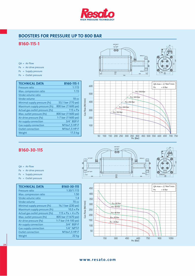
Actual gas outlet pressure (Po)
Max. outlet pressure (Po)
Air drive pressure (Pa)
Air supply connection
Gas supply connection
Outlet connection
Weight
1:1151:15
-18 cc
53,1 bar (770 psi)800 bar (11600 psi)
115 x Pa800 bar (11600 psi)1-7 bar (11600 psi)
3/4'' BSP-FM16x1,5 HP-FM16x1,5 HP-F
17,5 kg
Po (Bar)
Ga
s fl
ow
(N
l/m
in)
05 005054004053003052002051001
001
002
003
004
005
006055 056 057007
006QA max = 2,7 Nm3/min
Pa = 6 Bar
Ps= 300 Bar
Ps= 350 Bar
Ps= 250 Bar
Ps= 200 Bar
Ps= 150 Bar
TECHNICAL DATA B160-30-115Pressure ratio
Max. compression ratio
Stroke volume ratio
Stroke volume
Minimal supply pressure (Ps)
Maximum supply pressure (Ps)
Actual gas outlet pressure (Po)
Max. outlet pressure (Po)
Air drive pressure (Pa)
Air supply connection
Gas supply connection
Outlet connection
Weight
1:30/1:1151:501:4
70 cc16,1 bar (230 psi)
10,5 x Pa115 x Pa + 4 x Ps
805 bar (11670 psi)1-7 bar (14-100 psi)
3/4'' BSP-F1/4'' NPT-F
M16x1,5 HP-F22 kg
AIR INLET
3/4’’BSP
M16x1,5
M16x1,5
341 168 168 709
110 M6(x4)
170
66
170
239
290
1/4'' NPT
1/4'' NPT
17,5 16,5
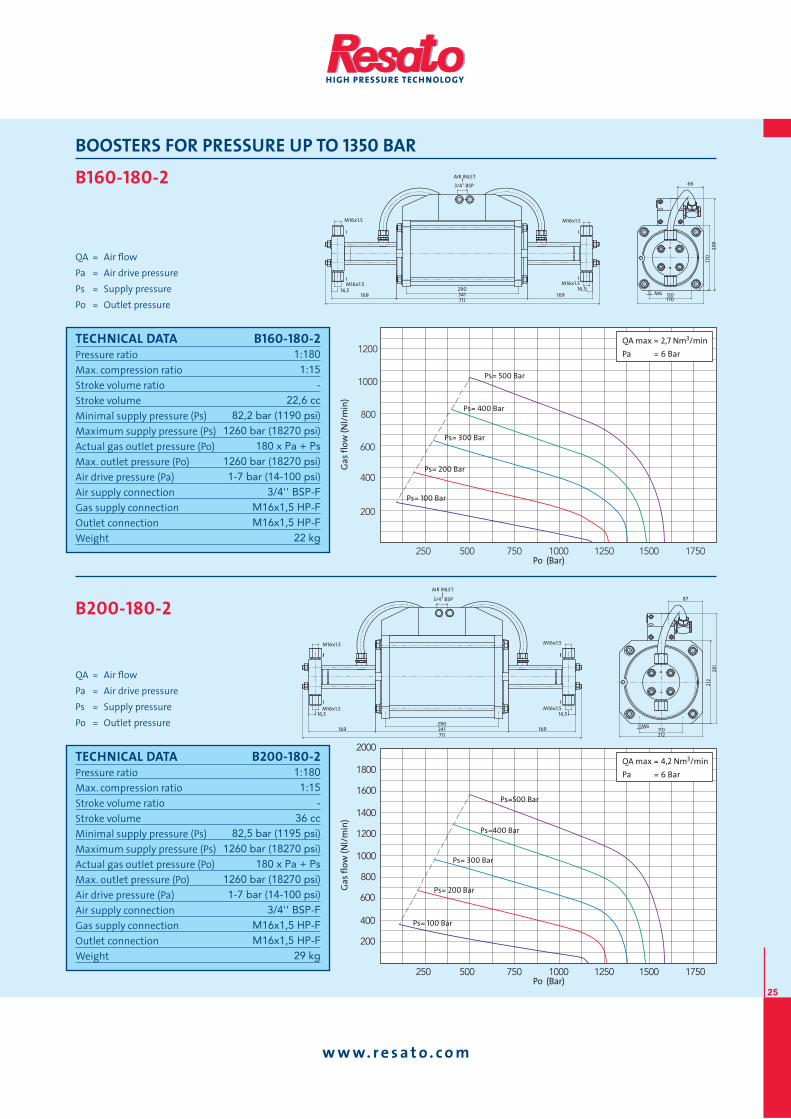
www. re sa to . com
25
BOOSTERS FOR PRESSURE UP TO 1350 BAR
B160-180-2
QA = Air fl ow
Pa = Air drive pressure
Ps = Supply pressure
Po = Outlet pressure
B200-180-2
QA = Air fl ow
Pa = Air drive pressure
Ps = Supply pressure
Po = Outlet pressure
Po (Bar)
Ga
s fl
ow
(N
l/m
in)
0001057005052
002
004
006
008
0001
0051 05710521
0021
0081
0002
0041
0061
QA max = 4,2 Nm3/min
Pa = 6 Bar
Ps= 300 Bar
Ps=400 Bar
Ps=500 Bar
Ps= 200 Bar
Ps= 100 Bar
110 M6
212
87
212
281
AIR INLET
3/4'' BSP
16,5 16,5
169 169 290 341 711
M16x1.5
M16x1.5
M16x1.5
M16x1.5
TECHNICAL DATA B160-180-2Pressure ratio
Max. compression ratio
Stroke volume ratio
Stroke volume
Minimal supply pressure (Ps)
Maximum supply pressure (Ps)
Actual gas outlet pressure (Po)
Max. outlet pressure (Po)
Air drive pressure (Pa)
Air supply connection
Gas supply connection
Outlet connection
Weight
1:1801:15
-22,6 cc
82,2 bar (1190 psi)1260 bar (18270 psi)
180 x Pa + Ps1260 bar (18270 psi)1-7 bar (14-100 psi)
3/4'' BSP-FM16x1,5 HP-FM16x1,5 HP-F
22 kg
Po (Bar)
Ga
s fl
ow
(N
l/m
in)
0001057005052
002
004
006
008
0001
0051 05710521
0021
Ps= 500 Bar
Ps= 400 Bar
Ps= 300 Bar
Ps= 200 Bar
Ps= 100 Bar
QA max = 2,7 Nm3/min
Pa = 6 Bar
TECHNICAL DATA B200-180-2Pressure ratio
Max. compression ratio
Stroke volume ratio
Stroke volume
Minimal supply pressure (Ps)
Maximum supply pressure (Ps)
Actual gas outlet pressure (Po)
Max. outlet pressure (Po)
Air drive pressure (Pa)
Air supply connection
Gas supply connection
Outlet connection
Weight
1:1801:15
-36 cc
82,5 bar (1195 psi)1260 bar (18270 psi)
180 x Pa + Ps1260 bar (18270 psi)1-7 bar (14-100 psi)
3/4'' BSP-FM16x1,5 HP-FM16x1,5 HP-F
29 kg
110 M6 170
66
170
239
AIR INLET
3/4'' BSP
M16x1.5
M16x1.5
M16x1.5
M16x1.5
16,5 16,5 169 169
290 341 711
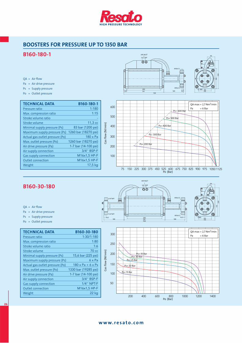
www. re sa to . com
26
BOOSTERS FOR PRESSURE UP TO 1350 BAR
B160-180-1
QA = Air fl ow
Pa = Air drive pressure
Ps = Supply pressure
Po = Outlet pressure
AIR INLET
3/4'' BSP
M16x1.5
341 526
169 110 M6 170
66
170
239
290 M16x1.5
16,5 25,5
B160-30-180
QA = Air fl ow
Pa = Air drive pressure
Ps = Supply pressure
Po = Outlet pressure
Po (Bar)
Ga
s fl
ow
(N
l/m
in)
05
001
051
002
052
003
004100210001008006004002
QA max = 2,7 Nm3/min
Pa = 6 Bar
Ps= 30 BarPs= 35 Bar
Ps= 25 Bar
Ps= 20 Bar
Ps= 15 Bar
TECHNICAL DATA B160-180-1Pressure ratio
Max. compression ratio
Stroke volume ratio
Stroke volume
Minimal supply pressure (Ps)
Maximum supply pressure (Ps)
Actual gas outlet pressure (Po)
Max. outlet pressure (Po)
Air drive pressure (Pa)
Air supply connection
Gas supply connection
Outlet connection
Weight
1:1801:15
-11,3 cc
83 bar (1200 psi)1260 bar (18270 psi)
180 x Pa1260 bar (18270 psi)1-7 bar (14-100 psi)
3/4'' BSP-FM16x1,5 HP-FM16x1,5 HP-F
17,5 kg
Po (Bar)
Ga
s fl
ow
(N
l/m
in)
57 057576006525054573003522051
001
002
003
004
006
009528 579 52110501
005
QA max = 2,7 Nm3/min
Pa = 6 Bar
Ps= 500 Bar
Ps= 600 Bar
Ps= 400 Bar
Ps= 300 Bar
Ps= 200 Bar
TECHNICAL DATA B160-30-180Pressure ratio
Max. compression ratio
Stroke volume ratio
Stroke volume
Minimal supply pressure (Ps)
Maximum supply pressure (Ps)
Actual gas outlet pressure (Po)
Max. outlet pressure (Po)
Air drive pressure (Pa)
Air supply connection
Gas supply connection
Outlet connection
Weight
1:30/1:1801:801:6
70 cc15,6 bar (225 psi)
6 x Pa180 x Pa + 6 x Ps
1330 bar (19285 psi)1-7 bar (14-100 psi)
3/4'' BSP-F1/4'' NPT-F
M16x1,5 HP-F22 kg
AIR INLET
3/4'' BSP
M16x1,5
M16x1,5
341 709
168 168 110 17
0 23
9 M6
170
66
290 16,5 16,5
1/4’’NPT
1/4’’NPT
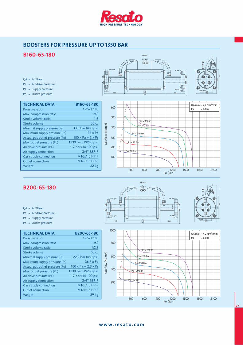
www. re sa to . com
27
BOOSTERS FOR PRESSURE UP TO 1350 BAR
B160-65-180
QA = Air fl ow
Pa = Air drive pressure
Ps = Supply pressure
Po = Outlet pressure
AIR INLET
3/4’’BSP
M16x1,5
M16x1,5
341 169 169 711
110 M6(x4) 170
66
170
239
290
M16x1.5
16,5 16,5
B200-65-180
QA = Air fl ow
Pa = Air drive pressure
Ps = Supply pressure
Po = Outlet pressure
Po (Bar)
Ga
s fl
ow
(N
l/m
in)
009006003 0012008100510021
002
004
008
0001
006
QA max = 4,2 Nm3/min
Pa = 6 Bar
QA max = 4,2 Nm3/min
Pa = 6 Bar
Ps= 170 Bar
Ps= 210 Bar
Ps= 130 Bar
Ps= 90 Bar
Ps= 50 Bar
AIR INLET
3/4’’BSP
1/4'' NPT
1/4'' NPT
341 168 168 711
110 M6 212
87
212
281 290
1/4'' NPT
1/4'' NPT
16,5 16,5
TECHNICAL DATA B160-65-180Pressure ratio
Max. compression ratio
Stroke volume ratio
Stroke volume
Minimal supply pressure (Ps)
Maximum supply pressure (Ps)
Actual gas outlet pressure (Po)
Max. outlet pressure (Po)
Air drive pressure (Pa)
Air supply connection
Gas supply connection
Outlet connection
Weight
1:65/1:1801:401:3
30 cc33,3 bar (480 psi)
36 x Pa180 x Pa + 3 x Ps
1330 bar (19285 psi)1-7 bar (14-100 psi)
3/4'' BSP-FM16x1,5 HP-FM16x1,5 HP-F
22 kg
Po (Bar)
Ga
s fl
ow
(N
l/m
in)
009006003 0012008100510021
001
002
003
004
005
006QA max = 2,7 Nm3/min
Pa = 6 Bar
Ps= 170 Bar
Ps= 210 Bar
Ps= 130 Bar
Ps= 99 Bar
Ps= 50 Bar
TECHNICAL DATA B200-65-180Pressure ratio
Max. compression ratio
Stroke volume ratio
Stroke volume
Minimal supply pressure (Ps)
Maximum supply pressure (Ps)
Actual gas outlet pressure (Po)
Max. outlet pressure (Po)
Air drive pressure (Pa)
Air supply connection
Gas supply connection
Outlet connection
Weight
1:65/1:1801:601:2,850 cc
22,2 bar (480 psi)36,7 x Pa
180 x Pa + 2,8 x Ps1330 bar (19285 psi)1-7 bar (14-100 psi)
3/4'' BSP-FM16x1,5 HP-FM16x1,5 HP-F
29 kg
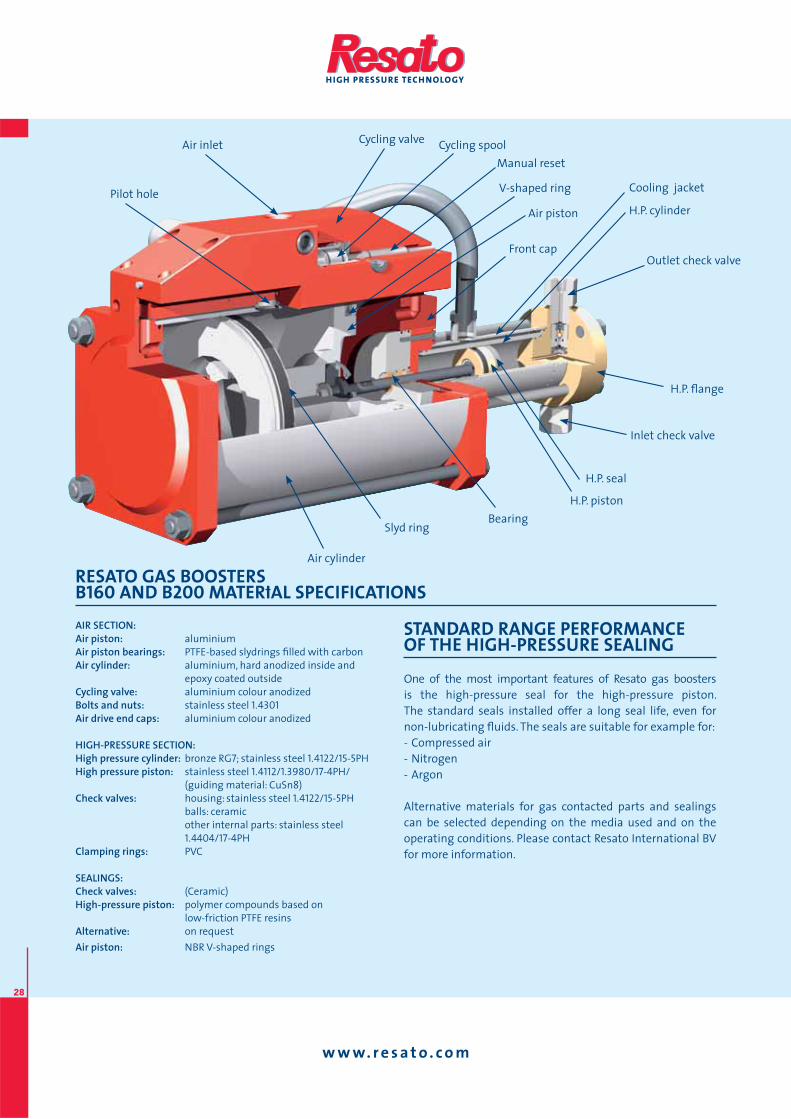
www. re sa to . com
28
RESATO GAS BOOSTERS B160 AND B200 MATERIAL SPECIFICATIONS
AIR SECTION:Air piston: aluminium
Air piston bearings: PTFE-based slydrings fi lled with carbon
Air cylinder: aluminium, hard anodized inside and
epoxy coated outside
Cycling valve: aluminium colour anodized
Bolts and nuts: stainless steel 1.4301Air drive end caps: aluminium colour anodized
HIGH-PRESSURE SECTION:High pressure cylinder: bronze RG7; stainless steel 1.4122/15-5PH
High pressure piston: stainless steel 1.4112/1.3980/17-4PH/
(guiding material: CuSn8)
Check valves: housing: stainless steel 1.4122/15-5PH
balls: ceramic
other internal parts: stainless steel
1.4404/17-4PH
Clamping rings: PVC
SEALINGS:Check valves: (Ceramic)
High-pressure piston: polymer compounds based on
low-friction PTFE resins
Alternative: on request
Air piston: NBR V-shaped rings
STANDARD RANGE PERFORMANCE OF THE HIGH-PRESSURE SEALING
One of the most important features of Resato gas boosters
is the high-pressure seal for the high-pressure piston.
The standard seals installed offer a long seal life, even for
non-lubricating fl uids. The seals are suitable for example for:
- Compressed air
- Nitrogen
- Argon
Alternative materials for gas contacted parts and sealings
can be selected depending on the media used and on the
operating conditions. Please contact Resato International BV
for more information.
Air inlet
Pilot hole
Cycling valve Cycling spool
Manual reset
V-shaped ring
Air piston
Outlet check valve
H.P. seal
H.P. piston
Bearing Slyd ring
Air cylinder
H.P. fl ange
Inlet check valve
H.P. cylinder
Cooling jacket
Front cap
www. re sa to . com
29
AIR CONTROLS
Every Resato air driven gas booster must be fi tted with a
set of air controls to control gas booster performance, to
lubricate the air and to prevent dirt and water from entering
the air drive section. All air controls for the B160 range have
1/2'' BSP connections; air controls for the B200 range have
3/4'' BSP connections.
The set of air controls can be delivered as one unit, or as two
separate units:
- unit for the B160 range, ordering code C-1/2- unit for the B200 range, ordering code C-3/4- fi lter/water separator with lubricator,
ordering code FL-1/2 (B160) or FL-3/4 (B200)
- air pressure regulator,
ordering code R-1/2 (B160) or R-3/4 (B200).
For the B160 range a start/stop valve is available which can
be connected directly to the air controls. Ordering code for
the start/stop valve is V-1/2.
EXHAUST MUFFLER
To suppress noise and prevent ingress of contamination into
the air cycling valve, the gas boosters are standard supplied
with exhaust muffl ers:
- type S-16 for the B160 range
- type S-20 for the B200 range.
If no exhaust muffl er is required or available and noise levels
are above acceptable, exhaust pipes can be led away to a
remote location.
BRACKETS
If for any reason the thread holes in the air drive end caps
cannot be used to mount the gas booster, four welding
brackets (4) can be used. The nuts of the air cylinder clamping
bolts can be used to mount the brackets to the gas booster.
Ordering code for the brackets is B-16/20 for booster types
B160 and B200.
ADAPTERS
Many booster types have a high-pressure connection (see
selection tables). If necessary, Resato can provide high-
pressure adapters with UNF high-pressure NPT or BSP thread
connections. Please refer to our catalogue of high-pressure
fi ttings, adapters and tubing for more information.
ORDERING EXAMPLE
B200 - 65 - 2 / EX
Booster range - Ratio - Double acting / Atex version
B160 series (refer to single (1) Standard
B200 series table) double (2) Atex version (EX)
two stage (eg 15-65) Oxygen clean (OX)
ACCESSOIRIES

www. re sa to . com
30
NOTES

www. re sa to . com
31
NOTES
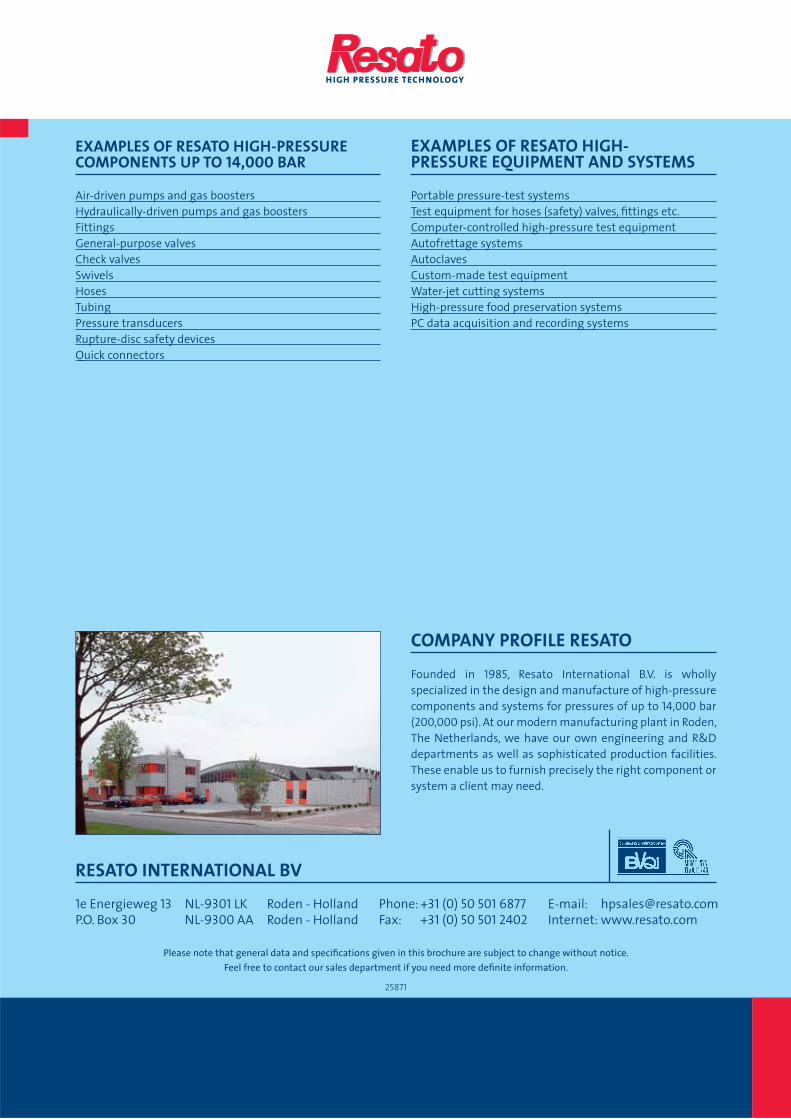
Please note that general data and specifi cations given in this brochure are subject to change without notice.
Feel free to contact our sales department if you need more defi nite information.
25871
RESATO INTERNATIONAL BV
1e Energieweg 13 NL-9301 LK Roden - Holland
P.O. Box 30 NL-9300 AA Roden - Holland
Phone: +31 (0) 50 501 6877Fax: +31 (0) 50 501 2402
COMPANY PROFILE RESATO
Founded in 1985, Resato International B.V. is wholly
specialized in the design and manufacture of high-pressure
components and systems for pressures of up to 14,000 bar
(200,000 psi). At our modern manufacturing plant in Roden,
The Netherlands, we have our own engineering and R&D
departments as well as sophisticated production facilities.
These enable us to furnish precisely the right component or
system a client may need.
EXAMPLES OF RESATO HIGH-PRESSURE COMPONENTS UP TO 14,000 BAR
Air-driven pumps and gas boosters
Hydraulically-driven pumps and gas boosters
Fittings
General-purpose valves
Check valves
Swivels
Hoses
Tubing
Pressure transducers
Rupture-disc safety devices
Quick connectors
EXAMPLES OF RESATO HIGH- PRESSURE EQUIPMENT AND SYSTEMS
Portable pressure-test systems
Test equipment for hoses (safety) valves, fi ttings etc.
Computer-controlled high-pressure test equipment
Autofrettage systems
Autoclaves
Custom-made test equipment
Water-jet cutting systems
High-pressure food preservation systems
PC data acquisition and recording systems
E-mail: [email protected]
Internet: www.resato.com