pneumatic instruments catalog - transmitter shop instruments catalog invensys plc 3rd floor ......
TRANSCRIPT

Pneumatic Instruments Catalog
Invensys plc 3rd Floor40 Grosvenor PlaceLondonSW1X 7AW United KingdomTel: +44 (0)203 155 1200www.invensys.com
Invensys, the Invensys logo, ArchestrA, Avantis, Eurotherm, Foxboro, IMServ, InFusion, SimSci-Esscor, Skelta, Triconex, and Wonderware are trademarks of Invensys plc, its subsidiaries or affiliates. All other brands and product names may be the trademarks or service marks of their representative owners.
© 2013 Invensys Systems, Inc. All rights reserved. No part of the material protected by this copyright may be reproduced or utilized in any form or by any means, electronic or mechanical, including photocopying, recording, broadcasting, or by any information storage and retrieval system, without permission in writing from Invensys Systems, Inc.
PN FX-0180 Rev. 04/13
Foxboro33 Commercial StreetFoxboro, Massachusetts 02035-2099 U.S.A.+1(866) 746-6477 Toll-free within U.S.A+1(508) 549-2424 Global
Foxboro EckardtPragstrasse 82D-70376 StuttgartGermanyTel +49 (0)711 502-0Fax +49 (0)711 502-597Email: [email protected]

33 Commercial StreetFoxboro, Massachusetts 02035-2099 U.S.A.
Your Foxboro representative:
1) SPECIFY MODEL NUMBER: 13 – – –Transmitter: 316 ss body ......................................................................................................... A Monel body ......................................................................................................... A4 Hastelloy C body (supplied without process connectors) ............................ A5
Span Limits: 5 and 62 kPa or 20 and 250 inH2O ΔP ...................................................................... M 50 and 210 kPa or 200 and 850 inH2O ΔP................................................................ H
Body Material: 316 ss (13A only) .................................................................................................................... S Monel (13A4 only) .................................................................................................................. M Hastelloy C (13A5 only) (Process Connectors code 0 below must be specified .......... C
Process Connectors: 1/4 NPT ............................................................................................................................................. 1 1/2 NPT ............................................................................................................................................. 2 R1/4 ................................................................................................................................................... 3 R1/2 ................................................................................................................................................... 4 Welding neck for 14 x 21 mm tube and 1/2 in Schedule 80 pipe ........................................... 6 None, body tapped for 1/4 NPT ................................................................................................... 0
Optional Features: (also see previous page) Zero elevation kit ....................................................................................................................................... L Zero suppression kit ................................................................................................................................. R
2) SPECIFY OUTPUT SIGNAL __________________________________________________ 3) SPECIFY CALIBRATED DIFFERENTIAL PRESSURE RANGE ______________________ 4) SPECIFY ADDITIONAL OPTIONAL FEATURES ________________________________ 5) SPECIFY INFORMATION FOR INSTRUMENT TAG _____________________________
Ordering
Specifying Your Instrument or AccessoryYou can easily specify many instruments and accessories described in this catalog. Sections covering our most popular items include all the technical data you need to know for most applications. To specify the appropriate item, simply follow the step-by-step procedure at the end of each description. Your Foxboro representative can help also.
For Example:Choose the product code.Itemize the information needed to complete the specification.
Ordering:To order, contact your Foxboro representative.Or call, in North America: 1-866-746-6477, or International: 001-508-549-2424.Or visit www.buyautomation.com/officelocator. Give us the ordering information using this catalog. Then tell us where you want the order shipped and when you need it delivered. We’ll do the rest.
Need Help? If you have questions, let us know. We’re ready, and eager, to assist you. Applications are a Foxboro specialty. We can help you figure out the best instrument for your purpose.
Instrument catalog available — ask your Foxboro representative about it.

Page 1
Table of Contents 1
Pneumatic Transmitters .................................................................Page 2 Differential Pressure .............................................................................................. 3 Flow .......................................................................................................................... 9 Pressure ................................................................................................................. 14 Repeater ................................................................................................................ 18 Liquid Level and Density ..................................................................................... 20 Temperature ......................................................................................................... 28 Filter Regulators .................................................................................................... 31 Miscellaneous ....................................................................................................... 32
Primary Measurement Elements ...........................................................33 Orifice Plates and Flange Unions ....................................................................... 29 IFOA Integral Flow Orifice Assemblies ............................................................. 36 Diaphragm Pressure Seals .................................................................................. 39 Thermowells and DEWCEL Dew Point Measurement Systems ..................... 40
Large Case Instruments .............................................................................41 3 Controllers ............................................................................................................. 42 Recorders and Indicators .................................................................................... 51 Recorders and Controllers .................................................................................. 54 Elements ................................................................................................................ 56 Miscellaneous ....................................................................................................... 65
Panel-Mounted Pneumatic Instruments ............................................66 4 Indicating Controllers .......................................................................................... 67 Recorders and Controllers .................................................................................. 73 Loading, Switching and Bias ............................................................................... 76 Subpanel ................................................................................................................ 78 Computing Elements ........................................................................................... 79 Computing Relay .................................................................................................. 81 Miscellaneous ....................................................................................................... 83
Converters ........................................................................................................84 5 Current-to-Pneumatic .......................................................................................... 85 Control Valves – Actuators .................................................................................. 90 Control Valves – Positioners ................................................................................ 91
Accessories and Supplies ..........................................................................92 6 Humitex Circular and Strip Charts ...................................................................... 92 Pens and Pen Arms .............................................................................................. 94
Product Index ............................................................................................99
Table of Contents

Page 2
Foxboro Pneumatic Transmitters are the industry standard.
All of these instruments have been field proven through years of experience. They are precise, easy to maintain, and available in a wide range of materials.
The Foxboro line encompasses a variety of measurement types.
Flow MeasurementDifferential pressure transmitters.
Temperature MeasurementFilled thermal systems and thermocouple/ RTD devices.
Pressure MeasurementForce balance and indicating transmitters.
Liquid Level MeasurementDifferential pressure transmitters with or without chemical seals and buoyancy transmitters.
Other ApplicationsSanitary designs, relative humidity trans mitters, speed transmitters, and repeaters.
Foxboro is the leading single source of pneumatic transmitters for the process industries.
No other manufacturer makes as many types for as many applications.
Pneumatic Transmitters

Page 3
Static Pressure, Span, and Range Limits
(a) Nonzero-based ranges require optional zero elevation or suppression kit. See “HOW TO ORDER.” Upper and lower range values must not exceed range limits. Negative numbers indicate a higher pressure on the normal “Low Side” of the transmitter, such as may occur in closed tank application with a wet leg.
15A, 13A, 13H SeriesPneumatic d/p CellTransmitters
The 15A, 13A, 13H Series Pneumatic d/p Cell Transmitters measure differential pressure and transmit a proportional pneumatic output signal.
Process Temperature Limits:-40 and +120°C (-40 and +250°F) at capsule.
Ambient Temperature Limits:-40 and +120°C (-40 and +250°F).
Accuracy:15A Series: ±0.5% of calibrated span.13A and 13H Series: ±0.5% of calibrated span except +0.75% of calibrated span for calibrated spans greater than 130 kPa or 525 inH20 ΔP.
Repeatability:0.1% of calibrated span.
Hysteresis:0.1% of calibrated span.
Output Signal and Suppiy Pressure:
n15A—low range transmitter adjustable for ranges from 0-1.3 to 0-6 kPa (0-5 to 0-25 inH20) ΔP at static pressures up to 3.5 MPa (500 psi)
n13A—adjustable for ranges from 0-5 to 0-210 kPa (0-20 to 0-850 inH20) ΔP at static pressures up to 14 MPa (2000 psi)
n13H—adjustable for ranges from 0-5 to 0-210 kPa (0-20 to 0-850 inH20) ΔP at static pressures up to 40 MPa (6000 psi)
nLow Air Consumption
For complete specifications, refer to Product Specification Sheet PSS 2B-1C1 A.
15A
13A
13H
Series MPa psi
15A 3.5 500
13A 14 2000
13H 40 6000
Static Pressure Limit
Output Signal Supply Pressure
20 to 100 kPa 140 kPa 3 to 15 psi 20 psi
Span kPa inH2O Series Code ΔP ΔP
15A L 1.3 and 6 5 and 25
13A and M 5 and 62 20 and 250 13H H 50 and 210 200 and 850
Span Limits
Span kPa inH2O Series Code ΔP ΔP
15A L ±12.5 ±50
13A and M ±62 ±250 13H H ±210 ±850
Range Limits (a)
Functional Specifications
Performance Specifications
15A, 13A, 13H
Pneumatic Transmitters (Differential Pressure)

Page 4
15A, 13A, 13H
Air Supply Set:Adjustable regulators with or without gauge.
High Process Temperature:Body temperature up to 190°C (375°F).
Integral Orifice:For low flow measurements. Refer to Page 31.
Bypass Manifolds:Refer to Page 27.
Oxygen Service Preparation:Cleaned and packaged for oxygen service.
Lower Spans:Provides spans as low as one-half standard.
Materials:Body Bolts: Alloy steel per ASTM A193 Grade B7; or 17-4 with Hastelloy C bodies.
Cover:High impact, glass filled polycarbonate.
Air Connections:The supply and output connections are tapped for 1/4 NPT.
Mounting:Direct to process or by bracket for DN 50 or 2 in horizontal or vertical pipe. Bracket is always supplied.
Enclosure Classification:Meets IEC IP53 and provides the environmental protection of NEMA Type 3.
Materials of Wetted Parts:
Capsule Materials:Hastelloy C, Monel, Duranickel, and tantalum.
HF Alkylation Service:Maximum life with economical materials.
Chlorine Service Preparation:Cleaned for chlorine service.
Hydrogen Service Preparation:Gold-plated capsule to prevent hydrogen penetration.
High Damping:Medium and low range capsules only.
NACE:Compliance to NACE Standard MR-01-75.
Series Wetted Part 15A, 13A, 13HA 13A4 13A5
Body AISI 316 ss Monel Hastelloy C Capsule Diaphragm 316L ss Monel 400 (a) Hastelloy C276 Other Capsule Parts 316 ss Monel Hastelloy C Force Bar 316 ss Monel Hastelloy C Force Bar Seal cobalt-nickel cobalt-nickel cobalt-nickel Force Bar Gasket silicone elastomer (b) Viton-A Viton-A Capsule Gaskets 316 ss Monel ptfe Process Connection Gaskets ptfe (c) ptfe (d)
(a) Duranickel capsule diaphragm material supplied when Span Limits code H is specified.(b) 13H Series uses Buna-N as standard.(c) 13H Series uses glass filled ptfe as standard.(d) Hastelloy C bodies are supplied without process connectors.
Optional Features
Physical Specifications
Pneumatic Transmitters (Differential Pressure)

Page 5
Pneumatic Transmitters (Differential Pressure)
15A, 13A, 13H
How to Order1) SPECIFY MODEL NUMBER: 15 - L - Transmitter: 316 ss body ...................................................................................................................A
Span Limits: 1.3 and 6 kPa or 5 and 25 inH20 ΔP .....................................................................................L
Body Material: 316 ss (15A only) ............................................................................................................................ S
Process Connectors: 1/4 NPT .....................................................................................................................................................1 1/2 NPT .....................................................................................................................................................2 R1/4 (metric) ............................................................................................................................................3 R1/2 (metric) ............................................................................................................................................4 Welding neck for 14 x 21 mm tube and 1/2 in Schedule 80 pipe ...................................................6 None, body tapped for 1/4 NPT ...........................................................................................................0
Optional Features: (also see previous page) Zero elevation kit ............................................................................................................................................. L Zero suppression kit ....................................................................................................................................... R
1) SPECIFY MODEL NUMBER: 13 ____ - ___ ___ ___ - ___
Transmitter: 316 ss body ...................................................................................................................A Monel body ..................................................................................................................A4 Hastelloy C body (supplied without process connectors) .....................................A5
Span Limits: 5 and 62 kPa or 20 and 250 inH20 ΔP ................................................................................M 50 and 210 kPa or 200 and 850 inH20 ΔP .......................................................................... H
Body Material: 316 ss (13A only) ............................................................................................................................ S Monel (13A4 only) ......................................................................................................................... M Hastelloy C (13A5 only) (Process Connectors code 0 below must be specified) .................C
Process Connectors: 1/4 NP .......................................................................................................................................................1 1/2 NP .......................................................................................................................................................2 R1/4 ...........................................................................................................................................................3 R1/2 ...........................................................................................................................................................4 Welding neck for 14 x 21 mm tube and 1/2 in Schedule 80 pipe ...................................................6 None, body tapped for 1/4 NPT ...........................................................................................................0
Optional Features: (also see previous page) Zero elevation kit ..............................................................................................................................................L Zero suppression kit ........................................................................................................................................R
HOW TO ORDER Continued on Next Page.

Page 6
1) SPECIFY MODEL NUMBER: 13H ____ - ___ ___ ___ - ___Transmitter: 316 ss body ................................................................................................................. A
Span Limits: 5 and 62 kPa or 20 and 250 inH20 ΔP ................................................................................M 50 and 210 kPa or 200 and 850 inH20 ΔP .......................................................................... H
Body Material: 316 ss (13HA only) ......................................................................................................................... S
Process Connectors: (a) 1/4 NPT .....................................................................................................................................................1 1/2 NPT .....................................................................................................................................................2 R1/4 .......................................................................................................................................................3 R1/2 .......................................................................................................................................................4 None, body tapped for 9/16-18 Aminco fitting ..................................................................................5 None, body tapped for 1/4 NPT ...........................................................................................................0
Optional Features: (also see Page 4) Zero elevation kit ............................................................................................................................................. L Zero suppression kit .......................................................................................................................................R
(a) The transmitter is normally supplied with body tapped for 1/4 NPT unless Process Connectors code 5 is specified.
2) SPECIFY OUTPUT SIGNAL _________________________________________________________3) SPECIFY CALIBRATED DIFFERENTIAL PRESSURE RANGE ____________________________4) SPECIFY ADDITIONAL OPTIONAL FEATURES _______________________________________5) SPECIFY INFORMATION FOR INSTRUMENT TAG ___________________________________
Pneumatic Transmitters (Differential Pressure)
15A, 13A, 13H
How to Order (continued)
Page 7
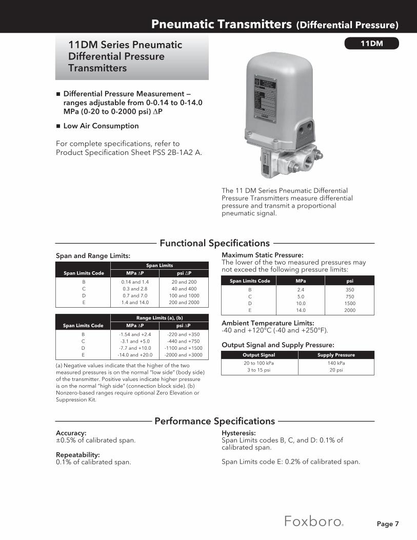
The 11 DM Series Pneumatic Differential Pressure Transmitters measure differential pressure and transmit a proportional pneumatic signal.
Hysteresis:Span Limits codes B, C, and D: 0.1% of calibrated span.
Span Limits code E: 0.2% of calibrated span.
Maximum Static Pressure:The lower of the two measured pressures may not exceed the following pressure limits:
Ambient Temperature Limits:-40 and +120°C (-40 and +250°F).
Output Signal and Supply Pressure:
Accuracy:±0.5% of calibrated span.
Repeatability:0.1% of calibrated span.
Span and Range Limits:
(a) Negative values indicate that the higher of the two measured pressures is on the normal “low side” (body side) of the transmitter. Positive values indicate higher pressure is on the normal “high side” (connection block side). (b) Nonzero-based ranges require optional Zero Elevation or Suppression Kit.
nDifferential Pressure Measurement —ranges adjustable from 0-0.14 to 0-14.0 MPa (0-20 to 0-2000 psi) ΔP
nLow Air Consumption
For complete specifications, refer to Product Specification Sheet PSS 2B-1A2 A.
11DM
Pneumatic Transmitters (Differential Pressure)
Output Signal Supply Pressure
20 to 100 kPa 140 kPa 3 to 15 psi 20 psi
Span Limits Code MPa ΔP psi ΔP
B 0.14 and 1.4 20 and 200 C 0.3 and 2.8 40 and 400 D 0.7 and 7.0 100 and 1000 E 1.4 and 14.0 200 and 2000
Span Limits
Span Limits Code MPa ΔP psi ΔP
B -1.54 and +2.4 -220 and +350 C -3.1 and +5.0 -440 and +750 D -7.7 and +10.0 -1100 and +1500 E -14.0 and +20.0 -2000 and +3000
Range Limits (a), (b)
Span Limits Code MPa psi
B 2.4 350 C 5.0 750 D 10.0 1500 E 14.0 2000
Functional Specifications
Performance Specifications
11DM Series PneumaticDifferential PressureTransmitters
Page 8
Pneumatic Transmitters (Differential Pressure)
11DM
Enclosure Classification:Meets IEC IP53 and provides the environmental protection of NEMA Type 3.
Mounting:Bracket for DN 50 or 2 in vertical or horizontal pipe.
Air Connections:The supply and output connections are tapped for 1/4 NPT.
Body Bolts:Alloy steel per ASTM A193 Grade B7.
Cover:High impact, glass filled polycarbonate.
Materials of Wetted Parts:316 ss = AISI Type 316 stainless steel.316L ss = AISI Type 316L stainless steel
Oxygen Service Preparation:Cleaned and packaged for oxygen service.
NACE:Compliance to NACE Standard MR-01-71.
Body 316 ss Capsule Bellows 316L ss or Monel Other Capsule Parts 316 ss or Monel Force Bar 316 ss Force Bar Seal cobalt-nickel Force Bar Gasket silicone elastomer Capsule Gasket silicone elastomer
1) SPECIFY MODEL NUMBER: 11DM- ___ ___ ___ - ___Span Limits: 0.14 and 1.4 MPa or 20 and 200 psi ..........................................................................B 0.3 and 2.8 MPa or 40 and 400 psi.............................................................................C 0.7 and 7.0 MPa or 100 and 1000 psi ........................................................................D 1.4 and 14 MPa or 200 and 2000 psi .........................................................................E
Wetted Parts: 316ss ......................................................................................................................................S 316 ss except Monel bellows assembly ............................................................................. D
Process Connection: 1/4 NPT .....................................................................................................................................................1 1/2 NPT .....................................................................................................................................................2 R1/4 (metric) ............................................................................................................................................3 R 1/2 (metric.............................................................................................................................................4
Optional Features: (also see previous page) Zero elevation .................................................................................................................................................. L Zero suppression.............................................................................................................................................R
2) SPECIFY OUTPUT SIGNAL _________________________________________________________3) SPECIFY CALIBRATED PRESSURE RANGE __________________________________________4) SPECIFY OPTIONAL FEATURES ____________________________________________________5) SPECIFY INFORMATION FOR INSTRUMENT TAG ___________________________________
Physical Specifications
How To Order
Optional Features

Page 9
The 14A Series Pneumatic Flow Integrator receives signal from transmitter, extracts square root, and totalizes flow on integral counter in engineering units.
Counter:6-digit, nonreset.
Count Rates and Integrator Factors:Count rate upper range values are shown in the following table. Integrated flow is displayed direct-ly when the count rate is set equal to the maximum flow rate. Other flow rates can be accommodated using the count rate times the integrator factor. Example: Reading x 100 = Gallons.
Available Count Rate:Upper Range Values
nDurable • Self-cleaning, self-aligning ball and thrust
plate bearings • Gasketed cast aluminum cover
nVersatile • Field or panel mounting up to several
hundred feet from point of measurement
nStable • Force balance unit minimizes variations in
air supply pressure or ambient temperature
nMultiple Ranges • Changeable counting speed can match
almost any flow range • No recalibration required
For complete specifications, refer to General Specification Sheet GS 2B-5A1 A.
14A
Pneumatic Transmitters (Flow)
Input Signal and Suppiy Pressure Intput Signal Supply Pressure
20 to 100 kPa 140 kPa 3 to 15 psi 20 psi
Counts per Minute Counts per Hour Counts per Day 4.75 to 49.21 285 to 2953 6840 to 70870 excluding: excluding: excluding: 5.46 to 5.54, 328 to 332, 7870 to 7980, 9.11 to 9.50, 547 to 570, 13120 to 13680, and and and 10.93 to 11.08 656 to 665 15750 to 15960
Functional Specifications
14A Series PneumaticFlow Integrators

Page 10
Pneumatic Transmitters (Flow)
14A
Integral Mounting to d/p Cell Transmitter:For 14A-F. Supply regulator included with this option.
Input Signal:Input cutoff point set for approximately 7% flow. Input startup point set for approximately 11 % flow.
Accuracy:±0.5% of full scale calibrated between 30 and 100% of flow.
Repeatability:0.2% of full scale.
Foxboro and CSA Certified:For use in Class I, Groups A, B. C, and D, Division 2. For EP Series only.
Body:Cast aluminum with acrylic enamel finish.
Specification Cover Case
High-impact, glass- 14A Series filled polycarbonate, — gasketed, weatherproof.
Performance Specifications
Physical Specifications
Optional Features

Page 11
14A
Pneumatic Transmitters (Flow)
1) SPECIFY MODEL NUMBER: 14A- _________Integral Nonreset Counter: Panel-Mounted ............................................................................................................................................— Field-Mounted .............................................................................................................................................F Field-Mounted with supply regulator ......................................................................................................FR
3) SPECIFY INPUT SIGNAL ___________________________________________________________4) SPECIFY COUNTS PER MINUTE, HOUR, OR DAY
(AT MAXIMUM FLOW RATE) ______________________________________________________5) SPECIFY INTEGRATOR FACTOR ___________________________________________________6) SPECIFY INFORMATION FOR INSTRUMENT TAG ____________________________________
How to Order

Page 12
11GM, 11GH SeriesPneumatic GaugePressure Transmitters
Pneumatic Transmitters (Pressure)
11GM, 11GH
Ambient Temperature Limits:-40 and +120°C (-40 and +250°F).
Body Temperature Limits:11GM Series: -40 and +190°C (-40 and + 375°F).11GH Series: -40 and +120°C (-40 and +250°F).
Repeatability:11GM Series:Wetted Parts code S: 0.1% of calibrated span.Wetted Parts code M: 0.2% of calibrated span.
11GH Series:0.15% of calibrated span.
n11GM—pressure measurement ranges adjustable from 0-0.07 to 0 -14 MPa (0-10 to 0-2000 psi)
n11GH—pressure measurement ranges adjustable from 0-7.0 to 0- 80 MPa (0-1000 to 0-12000 psi)
nLow Air Consumption
For complete specifications, refer to Product Specification Sheet PSS 2B-1A3 A.
Span, Range, and Overrange Limits:
(a) Nonzero-based ranges require optional zero elevation or suppression kit. See “HOW TO ORDER.”
Accuracy:
The 11GM, 11GH Series Pneumatic Gauge Pressure Transmitters measure gauge pressure and transmit a proportional pneumatic output signal.
Span Limits Series Code MPa psi
A 0.07 and 0.56 10 and 80 B 0.14 and 1.4 20 and 200 11GM C 0.3 and 2.8 40 and 400 D 0.7 and 7 100 and 1000 E 1.4 and 14 200 and 2000
11GH
K 7 and 40 1000 and 6000 N 14 and 80 2000 and 12000
Span Limits
Span Limits Series Code MPa psi
A - 0.1 and +0.6 -15 and +90 B - 0.1 and +2.4 -15 and +350 11GM C - 0.1 and +5 -15 and +750 D - 0.1 and +10 -15 and +1500 E - 0.1 and +20 -15 and +3000
11GH
K - 0.1 and +40 -15 and +6000 N - 0.1 and +80 -15 and +12000
Range Limits (a)
Span Limits Series Code MPa psi
A 0.7 100 B 3.5 500 11GM C 7 1000 D 14 2000 E 28 4000
11GH
K 62 9000 N 124 18000
Maximum Overrange Pressure Limit (b)
(b) Overrange limit of Span Limits code E with Wetted Parts code M on Page 13 is reduced to 21 MPa (3000 psi).
Output Signal and Suppiy Pressure Output Signal Supply Pressure
20 to 100 kPa 140 kPa 3 to 15 psi 20 psi
Spans Between Accuracy Series MPa psi (% of Span) 11GM All Spans ±0.5
11GH-K
7 and 20 1000 and 3000 ±0.5 20 and 40 3000 and 6000 ±1
11GH-N
14 and 40 2000 and 6000 ±0.5 40 and 80 6000 and 12000 ±1
Functional Specifications
Performance Specifications

Page 13
1) SPECIFY MODEL NUMBER: 11GM- ___ ___ ___ - ___Span Limits: 0.07 and 0.56 MPa or 10 and 80 psi .................................................................................. A 0.14 and 1.4 MPa or 20 and 200 psi .................................................................................. B 0.3 and 2.8 MPa or 40 and 400 psi..................................................................................... C 0.7 and 7 MPa or 100 and 1000 psi ................................................................................... D 1.4 and 14 MPa or 200 and 2000 psi ................................................................................. E
Wetted Parts: 316ss .............................................................................................................................................. S Monel (a) .........................................................................................................................................M
Process Connection: 1/4 NPT .....................................................................................................................................................1 1/2 NPT .....................................................................................................................................................2 R1/4 (metric) ............................................................................................................................................3 R1/2 (metric) ............................................................................................................................................4 Machined for 9/16-18 Aminco fitting (b) .............................................................................................5
Optional Features: (also see above) Zero elevation .................................................................................................................................................. L Zero suppression.............................................................................................................................................R
(a) Not available with Span Limits code A above.(b) Not available with Span Limits code A or Wetted Parts code M above.
HOW TO ORDER Continued on Next Page.
Materials:Cover: High-impact, glass-filled polycarbonate.
Body Bolts: Alloy steel per ASTM A193 Grade B7.
Enclosure Classification:Meets IEC IP53 and provides the environmental protection of NEMA Type 3.
Air Connections:The supply and output connections are tapped for 1/ 4 NPT.
High Accuracy Calibration (11GM only):Accuracy of +0.25% of calibrated span.
NACE (11 GM only):Compliance to NACE Standard MR-01-75.
Materials of Wetted Parts:
Air Supply Set:Adjustable regulators with or without gauge.
Pressure Seals:Refer to Page 34.
Oxygen Service Preparation:Cleaned and packaged for oxygen service.
11GM, 11GH
Wetted Parts Code Item S M C Element 316ss Monel Ni-Span
Connection 316ss Monel 316ss Block
Connection Silicone Viton-A (none)
Gasket Elastomer
Pneumatic Transmitters (Pressure)
Optional Features
Physical Specifications
How to Order

Page 14
1) SPECIFY MODEL NUMBER: 11GH- ___ ___ ___ - ___ C
Span Limits: 7 and 40 MPa or 1000 and 6000 psi .................................................................................. K 14 and 80 MPa or 2000 and 12000 psi .............................................................................. N
Wetted Parts: Ni-Span element with 316 ss connection ...................................................................................C
Process Connection: 1/2 NPT .....................................................................................................................................................2 R 1/2 (metric) ...........................................................................................................................................4 Machined for 9/16-18 Aminco fitting ...................................................................................................5
Optional Features: (also see previous page) Zero elevation .................................................................................................................................................. L Zero suppression.............................................................................................................................................R
2) SPECIFY OUTPUT SIGNAL _________________________________________________________3) SPECIFY CALIBRATED PRESSURE RANGE __________________________________________4) SPECIFY OPTIONAL FEATURES ____________________________________________________5) SPECIFY INFORMATION FOR INSTRUMENT TAG ___________________________________
Pneumatic Transmitters (Pressure)
11GM, 11GH
How to Order (continued)

Page 15
The 11AL, 11AM, 11AH Series Pneumatic Absolute Pressure Transmitters measure absolute pressure and transmit a proportional pneumatic output signal.
Repeatability:11AL Series: 0.5% of calibrated span.
11AM, 11AH Series: 0.1% of calibrated span.
Hysteresis:11AL Series: 0.5% of calibrated span.
11AM Series: 0.25% of calibrated span.
11AH Series: 0.15% of calibrated span.
Maximum Process Temperature:120°C (250°F) at capsule.
Ambient Temperature Limits:-40 and + 120°C (-40 and +250°F).
Output Signal and Supply Pressure:
Accuracy:
Span, Range, and Overrange Limits (in absolute pressure units):
n11AL—adjustable for ranges from 0-1.3 to 0-5.3 kPa (0-10 to 040 mmHg) absolute
n11AM—adjustable for ranges from 0-5.3 to 0-200 kPa (0-40 to 01520 mmHg) absolute
n11AH—adjustable for ranges from 0-0.7 to 0-2.7 MPa (0-10 to 0400 psi) absolute
nLow air consumption
For complete specifications, refer to Product Specification Sheet PSS 2B-1A1 A.
11AL, 11AM, 11AH
Pneumatic Transmitters (Pressure)
11AM
11AH
11AL
(a) Nonzero-based ranges require optional zero suppression kit (standard for 11AM). See “HOW TO ORDER.”
Span Limits Range Limits (a) Series Code
11AL L 0 and 9.3 kPa 0 and 70 mmHg
11AM
M 0 and 53 kPa 0 and 400 mmHg H 0 and 200 kPa 0 and 1520 mmHg
A 0 and 0.62 MPa 0 and 90 psi 11AH B 0 and 2.4 MPa 0 and 350 psi C 0 and 5 MPa 0 and 750 psi
Span Limits Span Limits Series Code
11AL L 1.3 and 5.3kPa 10 and 40 mmHg
11AM
M 5.3 and 53 kPa 40 and 400 mmHg H 50 and 200 kPa 375 and 1520 mmHg
A 0.07 and 0.55 MPa 10 and 80 psi 11AH B 0.14 and 1.4 MP 20 and 200 psi C 0.3 and 2.7 MP 40 and 400 psi
Span Limits Series Code MPa psi
11AL L 0.8 115
11AM
M 0.8 115 H 1.1 165
A 0.7 100 11AH B 2.4 350 C 5.2 750
Maximum Overrange Pressure Limit
Output Signal Supply Pressure
20 to 100 kPa 140 kPa 3 to 15 psi 20 psi
Spans Between Accuracy Series kPa mmHg (% of Span)
11AL All Spans ±1.0%
11AM-M
5.3 and 13 40 and 100 ±0.5% 13 and 53 1100 and 400 ±1.0%
11 AM-H
50 and 113 |375 and 850 ±0.5% 113 and 200 1850 and 1520 ±1.0%
11AH All Spans ±0.5%
Functional Specifications
Performance Specifications
11AL, 11AM, 11AH SeriesPneumatic AbsolutePressure Transmitters

Page 16
1) SPECIFY MODEL NUMBER: 11AL- ___ ___ ___ – ___ L S
Span Limits: 1.3 and 5.3 kPa or 10 and 40 mmHg absolute ................................................................L
Body Material: AISI Type 316 stainless steel (316 ss) .........................................................................................S
Process Connections: Tapped for 1/4 NPT .............................................................................................................................. 1 Tapped for 1/2 NPT .............................................................................................................................. 2 Tapped for R1/4 (metric) ...................................................................................................................... 3 Tapped for R1/2 (metric) ...................................................................................................................... 4 Welding neck for 14 x 21 mm tube and 1/2 in Schedule 80 pipe ................................................. 6
Optional Zero Suppression ..........................................................................................................................R
HOW TO ORDER Continued on Next Page.
Pneumatic Transmitters (Pressure)
11AL, 11AM, 11AH
Oxygen Service Preparation:Cleaned and packaged for oxygen service.
Air Supply Sets:Adjustable regulators with or without output gauge.
Materials of Wetted Parts: Materials:Body Bolting: Alloy steel per ASTM A193 Grade B7.
Cover: High-impact, glass-filled polycarbonate.
Mounting:Bracket for nominal DN 50 or 2 in pipe.
Enclosure Classification:Meets IEC IP53 and provides the protection of NEMA Type 3.
Air Connections:The supply and output connections are tapped for 1/4 NPT.
(a) 11AH Series uses single silicone elastomer gasket as capsule and connector gasket.
Body Material Wetted Part AISI 316 ss Monel Capsule Diaphragm AISI 316L ss Monel Other Capsule Parts 316 ss Monel Force Bar 316 ss Monel Force Bar Seal cobalt-nickel cobalt-nickel Force Bar Gasket silicone elastomer Viton-A Capsule Gasket 316 ss (a) Monel Process Connector Gasket ptfe (a) ptfe
How to Order
Physical Specifications
Optional Features

Page 17
1) SPECIFY MODEL NUMBER: 11AH- ___ ___ ___ – ___ S
Span Limits: 0.07 and 0.55 MPa or 10 and 80 psi absolute ................................................................ A 0.14 and 1.4 MPa or 20 and 200 psi absolute .................................................................B 0.3 and 2.7 MPa or 40 and 400 psi absolute .................................................................. C
Body Material: 316 ss ............................................................................................................................................ S
Process Connections: Tapped for 1/2 NPT .............................................................................................................................. 2 Tapped for R1/2 (metric) ...................................................................................................................... 4
Optional Zero Suppression ..........................................................................................................................R
2) SPECIFY OUTPUT SIGNAL _________________________________________________________3) SPECIFY CALIBRATED ABSOLUTE PRESSURE RANGE _______________________________4) SPECIFY OPTIONAL FEATURES ____________________________________________________5) SPECIFY INFORMATION FOR INSTRUMENT TAG ___________________________________
1) SPECIFY MODEL NUMBER: 11AM - ___ ___ ___
Span Limits: 5.3 and 53 kPa or 40 and 400 mmHg absolute .............................................................. M 50 and 200 kPa or 375 and 1520 mmHg absolute ........................................................ H
Body Material: 316ss ............................................................................................................................................ S Monel Not available with Span Limits code H above .............................................................M
Process Connections: Tapped for 1/4 NPT .............................................................................................................................. 1 Tapped for 1/2 NPT .............................................................................................................................. 2 Tapped for R1/4 (metric) ...................................................................................................................... 3 Tapped for R1/2 (metric) ...................................................................................................................... 4 Welding neck for 14 x 21 mm tube and 1/2 in Schedule 80 pipe ................................................. 6
Pneumatic Transmitters (Pressure)
11AL, 11AM, 11AH
How to Order

Page 18
139PP
nReplacement for 17RnAdjustable up to 10 barn Overrange protection up to 16 barn Vacuum proofn With damping facilitiesn Version with exchangeable measuring
capsule, extended diaphragmn Version with welded in measuring
capsule, process side without gap, flush diaphragm
n Version for zero suppression to –0,5 barn Version with wetted parts in Tantalumn PTFE diaphragm protector
InputProcess pressure ....... 0.01 to 10 barRepeater with zero suppression ...... initial value adjustable from –0.05 to –0.5 barOverload limits .......... –1 bar and 16 barPTFE diaphragmprotector .................... 0 bar and 16 bar, not suitable for vacuum service
Ambient conditionsOperating temperature and application class:Repeater withoutzero suppression ........ –25 to +200 °Cwith zero suppression –25 to +125 °CTantalum version ........ –25 to +155 °CPTFE diaphragm ......... –25 to +100 °CStorage temperature .. –40 to +125 °CHumidity ....................... ≤ 100 %, condensation permittedProtection class ........... IP 54, IP 66
Error InfluenceAir supply fluctuation ............ ≤ 1 % / 0.1 barAmbient and processtemperature fluctuation:Repeater withoutzero suppression ................... ≤ 0.5 mbar / 10 Kwith zero suppression ........... ≤ 1 mbar / 10 KTantalum version ................... ≤ 2 mbar / 10 KPTFE diaphragm protector ... ≤ 1 mbar / 10 K
Accuracy:Output pressure up to 1 bar 2 bar 3 bar 4 bar 5 bar
Accuracy
Repeater without zero suppression (mbar) ≤1.5 ≤3 ≤6 ≤12 ≤20and Tantalum version
Repeater with zero suppression and (mbar)Repeater with PTFE diaphragm protector
≤3 ≤4 ≤7 ≤12 ≤20
Hysteresis
Repeater without zero suppression (mbar) <0.1 <0.2 <0.3 <0.5 <1
Repeater with zero suppression (mbar) <0.2 <0.3 <0.4 <0.6 <1
Tantalum version and (mbar)Repeater with PTFE diaphragm protector
≤0.5 ≤0.6 ≤0.7 ≤1 ≤1.5
Inherent Air Consumption (l/h) 120 160 210 260 360
Air Supply (bar) 1.4 2.5 4.5 6.5 11
Functional Specifications
Performance Specifications
Pneumatic Transmitters (Repeater)
139PP Pneumatic Pressure Repeater
For transmitting the pressure of corrosive, hot, gaseous, or liquid media or other fluids tending to solidify or clot. The pressure exerted by the medium is converted in a 1:1 ratio into a pneumatic pressure. For the repeater with zero suppression, the output is equal input plus suppression.
For complete specification, refer to Product Specification Sheet PSS EMP0140 A-(en)
Page 19
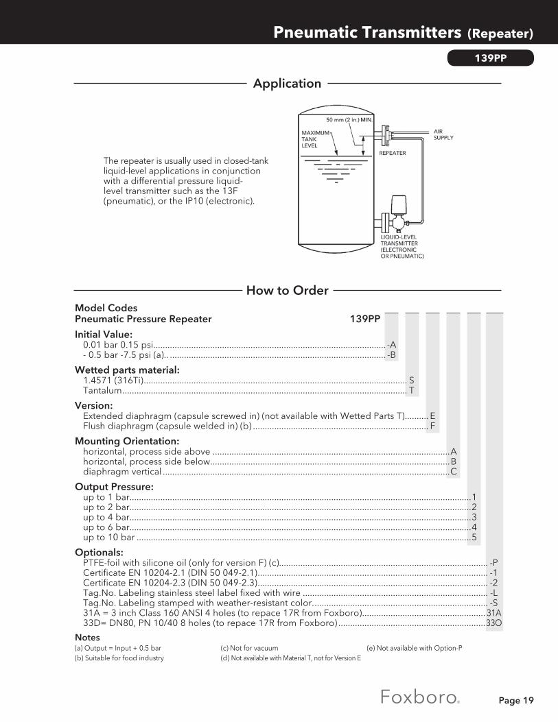
The repeater is usually used in closed-tank liquid-level applications in conjunction with a differential pressure liquid-level transmitter such as the 13F (pneumatic), or the IP10 (electronic).
Pneumatic Transmitters (Repeater)
139PP
How to OrderModel Codes Pneumatic Pressure Repeater 139PP Initial Value: 0.01 bar 0.15 psi.................................................................................................. -A - 0.5 bar -7.5 psi (a).. ........................................................................................... -B
Wetted parts material: 1.4571 (316Ti) ............................................................................................................... S Tantalum ........................................................................................................................ T
Version: Extended diaphragm (capsule screwed in) (not available with Wetted Parts T) .......... E Flush diaphragm (capsule welded in) (b) .......................................................................... F
Mounting Orientation: horizontal, process side above ....................................................................................................A horizontal, process side below .....................................................................................................B diaphragm vertical .........................................................................................................................C
Output Pressure: up to 1 bar................................................................................................................................................1 up to 2 bar................................................................................................................................................2 up to 4 bar................................................................................................................................................3 up to 6 bar................................................................................................................................................4 up to 10 bar .............................................................................................................................................5
Optionals: PTFE-foil with silicone oil (only for version F) (c)........................................................................................ -P Certificate EN 10204-2.1 (DIN 50 049-2.1) ................................................................................................. -1 Certificate EN 10204-2.3 (DIN 50 049-2.3) ................................................................................................. -2 Tag.No. Labeling stainless steel label fixed with wire .............................................................................. -L Tag.No. Labeling stamped with weather-resistant color. ......................................................................... -S 31A = 3 inch Class 160 ANSI 4 holes (to repace 17R from Foxboro) .................................................... 31A 33D= DN80, PN 10/40 8 holes (to repace 17R from Foxboro) ..............................................................33O
Notes(a) Output = Input + 0.5 bar(b) Suitable for food industry
(c) Not for vacuum(d) Not available with Material T, not for Version E
(e) Not available with Option-P
Application
Page 20
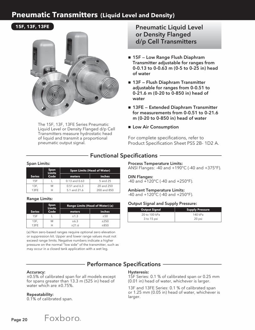
Pneumatic Liquid Levelor Density Flangedd/p Cell Transmitters
Pneumatic Transmitters (Liquid Level and Density)
15F, 13F, 13FE
Process Temperature Limits:ANSI Flanges: -40 and +190°C (-40 and +375°F).
DIN Flanges:-40 and +120°C (-40 and +250°F).
Ambient Temperature Limits:-40 and +120°C (-40 and +250°F).
Output Signal and Supply Pressure:
Hysteresis:15F Series: 0.1 % of calibrated span or 0.25 mm (0.01 in) head of water, whichever is larger.
13F and 13FE Series: 0.1 % of calibrated span or 1.25 mm (0.05 in) head of water, whichever is larger.
n15F — Low Range Flush Diaphram Transmitter adjustable for ranges from 0-0.13 to 0-0.63 m (0-5 to 0-25 in) head of water
n13F — Flush Diaphram Transmitter adjustable for ranges from 0-0.51 to 0-21.6 m (0-20 to 0-850 in) head of water
n13FE — Extended Diaphram Transmitter for measurements from 0-0.51 to 0-21.6 m (0-20 to 0-850 in) head of water
nLow Air Consumption
For complete specifications, refer to Product Specification Sheet PSS 2B- 1D2 A.
Span Limits:
Accuracy:±0.5% of calibrated span for all models except for spans greater than 13.3 m (525 in) head of water which are ±0.75%.
Repeatability:0.1% of calibrated span.
The 15F, 13F, 13FE Series Pneumatic Liquid Level or Density Flanged d/p Cell Transmitters measure hydrostatic head of liquid and transmit a proportional pneumatic output signal.
Span Limits Series Code meters inches
15F L 0.13 and 0.63 5 and 25
13F, M 0.51 and 6.3 20 and 250 13FE H 5.1 and 21.6 200 and 850
Span Limits (Head of Water)
Range Limits:
(a) Non zero-based ranges require optional zero elevation or suppression kit. Upper and lower range values must not exceed range limits. Negative numbers indicate a higher pressure on the normal “low side” of the transmitter, such as may occur in a closed tank application with a wet leg.
Span Limits Series Code meters inches
15F L ±1.3 ±50
13F, M ±6.3 ±250 13FE H ±21.6 ±850
Range Limits (Head of Water) (a) Output Signal Supply Pressure
20 to 100 kPa 140 kPa 3 to 15 psi 20 psi
Functional Specifications
Performance Specifications

Page 21
Mounting:Provided by process connection flange. See “HOW TO ORDER.”
Nominal Diaphragm Extension Length “A” (13FE Series): See “HOW TO ORDER.”
Flange Extension Length “B”:15F and 13FE Series: 125 mm (5 in).
13F Series: 125 or 200 mm (5 or 8 in), as specified.
Enclosure Classification:Meets IEC IP53 and provides the environmental protection of NEMA Type 3.
Cover Material:High-impact, glass-filled polycarbonate.
Lower Spans:Provides spans as low as one-half standard.
Air Supply Sets:Adjustable regulators with or without gauge.
Body and Flange Material:Zinc cobalt-plated carbon steel or 316 ss (b), as specified.
Materials of Wetted Parts:High Pressure Side: Capsule Diaphragm: 316L ss (c). Other Capsule Parts: 316 ss. Capsule Gaskets: 15F,13F Series: 316 ss. 13FE Series: None. Retaining Ring (d): 316 ss.Low Pressure Side (Partial List): Capsule Diaphragm: 316L ss. Force Bar: 316 ss. Force Bar Seal: Cobalt-nickel. Force Bar Gasket: Silicone elastomer. Capsule Gaskets: 15F, 13F Series: 316 ss. 13FE Series: ptfe.
(b) AISI Type 316 stainless steel. (c) AISI Type 316L stainless steel. (d) Raised face portion of flange.
Wetted Parts Materials:Monel, Duranickel, Hastelloy C, tantalum, and various coatings.
High Process Temperature:To 315°C (600°F).
15F, 13F, 13FE
Pneumatic Transmitters (Liquid Level and Density)
Optional Specifications
Physical Specifications
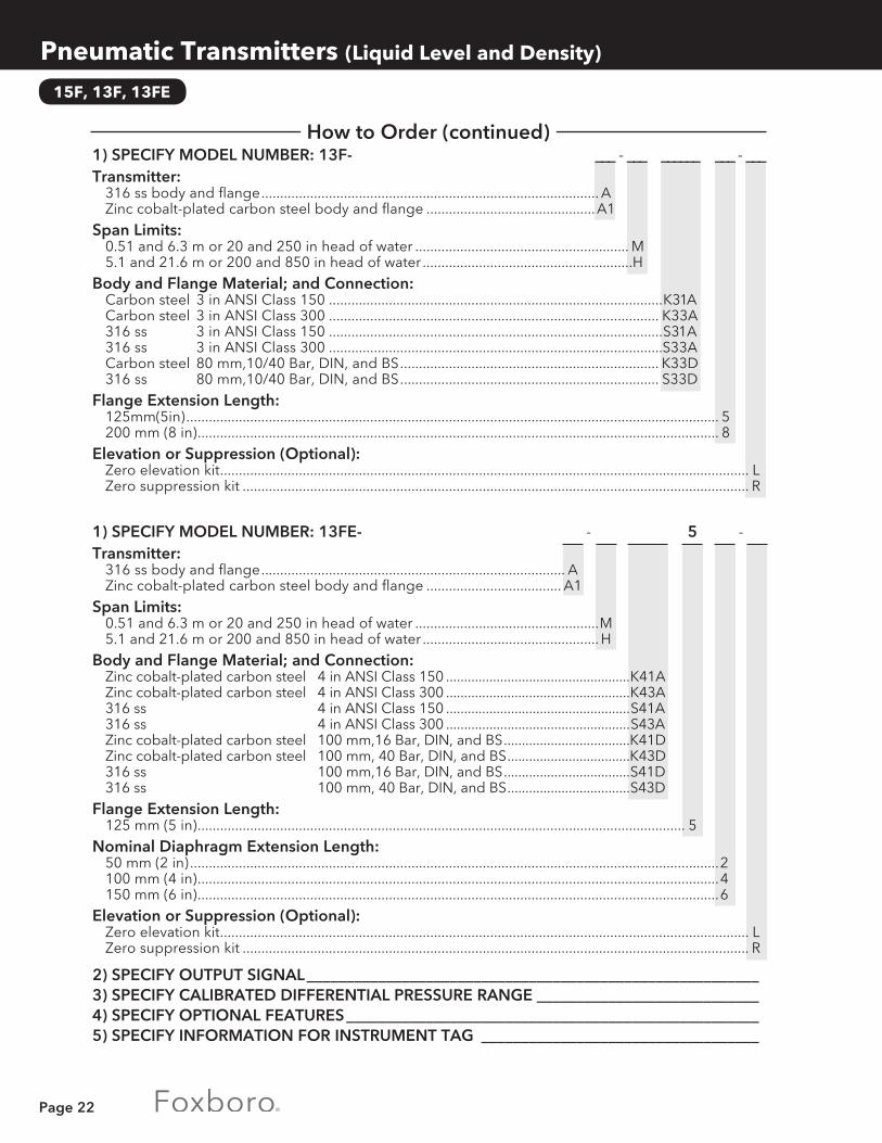
How to Order1) SPECIFY MODEL NUMBER: 15F- - L 5 - Transmitter: 316 ss body and flange ..........................................................................................A Zinc cobalt-plated carbon steel body and flange .............................................A1
Span Limits: 0.13 and 0.63 m or 5 and 25 in head of water ............................................................L
Body and Flange Material; and Connection: Zinc cobalt-plated carbon steel 6 in ANSI Class 150 ......................................................... K61A 316 ss 6 in ANSI Class 150 ..........................................................S61A Zinc cobalt-plated carbon steel 150 mm,16 Bar, DIN, and BS ......................................... K61D 316 ss 150 mm,16 Bar, DIN, and BS ......................................... S61D
Flange Extension Length: 125 mm (5 in) ........................................................................................................................................... 5
Elevation or Suppression (Optional): Zero elevation kit ............................................................................................................................................. L Zero suppression kit ....................................................................................................................................... R
HOW TO ORDER Continued on Next Page.
Page 22
15F, 13F, 13FE
How to Order (continued)1) SPECIFY MODEL NUMBER: 13F- ___ - ___ ______ ___ - ___Transmitter: 316 ss body and flange .......................................................................................... A Zinc cobalt-plated carbon steel body and flange .............................................A1
Span Limits: 0.51 and 6.3 m or 20 and 250 in head of water ......................................................... M 5.1 and 21.6 m or 200 and 850 in head of water ........................................................H
Body and Flange Material; and Connection: Carbon steel 3 in ANSI Class 150 .........................................................................................K31A Carbon steel 3 in ANSI Class 300 ........................................................................................ K33A 316 ss 3 in ANSI Class 150 .........................................................................................S31A 316 ss 3 in ANSI Class 300 .........................................................................................S33A Carbon steel 80 mm,10/40 Bar, DIN, and BS ..................................................................... K33D 316 ss 80 mm,10/40 Bar, DIN, and BS ..................................................................... S33D
Flange Extension Length: 125mm(5in) .............................................................................................................................................. 5 200 mm (8 in) ........................................................................................................................................... 8
Elevation or Suppression (Optional): Zero elevation kit ............................................................................................................................................. L Zero suppression kit ....................................................................................................................................... R
1) SPECIFY MODEL NUMBER: 13FE- - 5 - Transmitter: 316 ss body and flange ................................................................................. A Zinc cobalt-plated carbon steel body and flange .................................... A1
Span Limits: 0.51 and 6.3 m or 20 and 250 in head of water .................................................M 5.1 and 21.6 m or 200 and 850 in head of water ............................................... H
Body and Flange Material; and Connection: Zinc cobalt-plated carbon steel 4 in ANSI Class 150 ...................................................K41A Zinc cobalt-plated carbon steel 4 in ANSI Class 300 ...................................................K43A 316 ss 4 in ANSI Class 150 ...................................................S41A 316 ss 4 in ANSI Class 300 ...................................................S43A Zinc cobalt-plated carbon steel 100 mm,16 Bar, DIN, and BS ...................................K41D Zinc cobalt-plated carbon steel 100 mm, 40 Bar, DIN, and BS ..................................K43D 316 ss 100 mm,16 Bar, DIN, and BS ...................................S41D 316 ss 100 mm, 40 Bar, DIN, and BS ..................................S43D
Flange Extension Length: 125 mm (5 in) .................................................................................................................................. 5
Nominal Diaphragm Extension Length: 50 mm (2 in) .............................................................................................................................................2 100 mm (4 in) ...........................................................................................................................................4 150 mm (6 in) ...........................................................................................................................................6
Elevation or Suppression (Optional): Zero elevation kit ............................................................................................................................................. L Zero suppression kit ....................................................................................................................................... R
2) SPECIFY OUTPUT SIGNAL _________________________________________________________3) SPECIFY CALIBRATED DIFFERENTIAL PRESSURE RANGE ____________________________4) SPECIFY OPTIONAL FEATURES ____________________________________________________5) SPECIFY INFORMATION FOR INSTRUMENT TAG ___________________________________
Pneumatic Transmitters (Liquid Level and Density)
Page 23
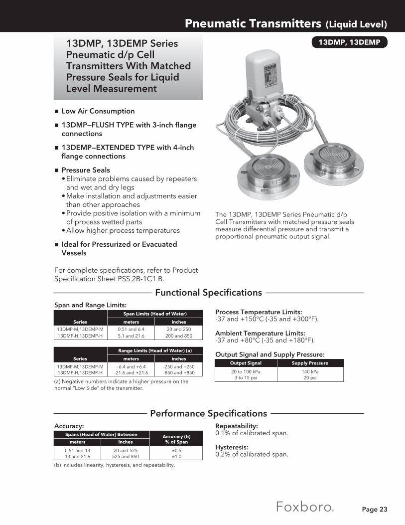
The 13DMP, 13DEMP Series Pneumatic d/p Cell Transmitters with matched pressure seals measure differential pressure and transmit a proportional pneumatic output signal.
Repeatability:0.1% of calibrated span.
Hysteresis:0.2% of calibrated span.
Process Temperature Limits:-37 and +150°C (-35 and +300°F).
Ambient Temperature Limits:-37 and +80°C (-35 and +180°F).
Output Signal and Supply Pressure:
Accuracy:
(b) Includes linearity, hysteresis, and repeatability.
nLow Air Consumption
n13DMP—FLUSH TYPE with 3-inch flange connections
n13DEMP—EXTENDED TYPE with 4-inch flange connections
nPressure Seals • Eliminate problems caused by repeaters and wet and dry legs • Make installation and adjustments easier than other approaches • Provide positive isolation with a minimum of process wetted parts • Allow higher process temperatures
nIdeal for Pressurized or Evacuated Vessels
For complete specifications, refer to Product Specification Sheet PSS 2B-1C1 B.
13DMP, 13DEMP
Pneumatic Transmitters (Liquid Level)
Span and Range Limits:
(a) Negative numbers indicate a higher pressure on the normal “Low Side” of the transmitter.
Output Signal Supply Pressure
20 to 100 kPa 140 kPa 3 to 15 psi 20 psi
Series meters inches
13DMP-M,13DEMP-M 0.51 and 6.4 20 and 250 13DMP-H,13DEMP-H 5.1 and 21.6 200 and 850
Span Limits (Head of Water)
Series meters inches
13DMP-M,13DEMP-M - 6.4 and +6.4 -250 and +250 13DMP-H,13DEMP-H -21.6 and +21.6 -850 and +850
Range Limits (Head of Water) (a)
Accuracy (b) meters inches % of Span
0.51 and 13 20 and 525 ±0.5 13 and 21.6 525 and 850 ±1.0
Spans (Head of Water) Between
13DMP, 13DEMP Series Pneumatic d/p Cell Transmitters With Matched Pressure Seals for Liquid Level Measurement
Functional Specifications
Performance Specifications

Page 24
Pneumatic Transmitters (Liquid Level)
13DMP, 13DEMP
Capillary Lengths:See “HOW TO ORDER.”
Mounting:Seals mount by process connection flanges. See “HOW TO ORDER.” Transmitter body mounts to bracket for DN 50 or 2 in vertical or horizontal pipe.
Enclosure Classification:Meets IEC IP53 and provides the environmental protection of NEMA Type 3.
Cover Material:High-impact, glass-filled polycarbonate.
Air Connections:The supply and output connections are tapped for 1/4 NPT.
High Temperature Fill:For process temperatures up to 300°C (580°F).
Materials of Wetted Parts:
Materials of Nonwetted Parts:
(c) Relative density (specific gravity) is 0.90 at 25°C (77°F).
Air Supply Set:Adjustable regulators with or without gauge.
Remote Seal Raised Face Backup Diaphragms Pads (Gasket Surface)
AISI Type 316L AISI Type 316 stainless steel stainless steel (316L ss) (316 ss)
Hastelloy C276 Hastelloy C
Tantalum
Description Material
Flanges 316 ss or carbon steel Capillary 316ss Transmitter Body 316ss Fill Fluid DC 200 silicone (c)
How to Order
Optional Specifications
Physical Specifications
1) SPECIFY MODEL NUMBER: 13DMP- ___ ___ ___ ______
Span Limits: 0.51 and 6.4 m or 20 and 250 in head of water ......................................................... M 5.1 and 21.6 m or 200 and 850 in head of water ....................................................... H
Wetted Parts Material: 316 ss with 316L ss diaphragm ..............................................................................................S Hastelloy C with Hastelloy C276 diaphragm ....................................................................... C Tantalum ....................................................................................................................................T
Capillary Length (each capillary): 1.5m( 5ft) ........................................................................................................................................... A 4.5m(15ft) .......................................................................................................................................... B 8 m (26 ft) .......................................................................................................................................... C
Process Connections (nonprocess wetted): Zinc cobalt-plated carbon steel 3 in ANSI Class 150 .......................................................................K31A Zinc cobalt-plated carbon steel 3 in ANSI Class 300 .......................................................................K33A Zinc cobalt-plated carbon steel 3 in ANSI Class 600 .......................................................................K36A 316 ss 3 in ANSI Class 150 .......................................................................S31A 316 ss 3 in ANSI Class 300 .......................................................................S33A 316 ss 3 in ANSI Class 600 .......................................................................S36A Zinc cobalt-plated carbon steel 80 mm 10/40 Bar, DIN and BS ....................................................K33D 316 ss 80 mm 10/40 Bar, DIN and BS ....................................................S33D
HOW TO ORDER Continued on Next Page.

Page 25
1) SPECIFY MODEL NUMBER: 13DEMP- ___ ___ ___ ___ ______
Span Limits: 0.51 and 6.4 m or 20 and 250 in head of water ................................................ M 5.1 and 21.6 m or 200 and 850 in head of water ...............................................H
Wetted Parts Material: 316 ss with 316L ss diaphragm ......................................................................................S Hastelloy C with Hastelloy C276 diaphragm ............................................................... C
Capillary Length (each capillary): 1.5m (5 ft) ................................................................................................................................. A 4.5m (15 ft) ............................................................................................................................... B 8m (26 ft) .................................................................................................................................. C
Extension Length: 50mm (2 in) ........................................................................................................................................2 100mm (4 in) ......................................................................................................................................4 150mm (6 in) ......................................................................................................................................6
Process Connections (nonprocess wetted): Carbon steel, 4 in ANSI Class 150 ....................................................................................................................................................K41A Class 300 ....................................................................................................................................................K43A Class 600 ....................................................................................................................................................K46A
2) SPECIFY OUTPUT SIGNAL _________________________________________________________3) SPECIFY CALIBRATED DIFFERENTIAL PRESSURE RANGE ____________________________4) SPECIFY OPTIONAL FEATURES ____________________________________________________5) SPECIFY INFORMATION FOR INSTRUMENT TAG ___________________________________
Note: For liquid level applications, zero elevation kits always required due to wet leg effect of filled seal system; therefore, it is a standard part of the 13DMP and 13 DEMP Series Transmitters.
13DMP, 13DEMP
Pneumatic Transmitters (Liquid Level)
How to Order (continued)

Page 26
167LP
nLevel transmission between vessel and transmitter by torque tube
nApplicable for service temperatures from –196°C to +400°C and pressures up to PN 250
nThe span can be set over a 1:5 rationA wide selection of materials facilitates
service under corrosive conditionsnMaterial opproval certificates to EN
10204-3.1 availablenVarious licences in accordance with
national regulationsnLicensed for use on sea ships in the
Germanische Lloyd class, or on other structures classified by Germanische Lloyd
InputMeasuring span ..........3 to 15 NDensity range ..............100 <ρ <1600 kg/m3
Standard lengths of displacers 204DE .......350 to 3000 mm 14 to 120 inchWeight of displacer ...max. 25 NOutput ..........................0.2 to 1 bar/3 to 15 psi/20 to 100 kPa/0.2 to 1 kp/cm2
Supply air .....................1.4 ±0.1 bar or 20 ±1.4 psi
Transitional BehaviorRelative error ..................<1%Sensitivity .........................<0.1%Ambient temperatureinfluence ..........................<0.2%/10 KProcess temperatureinfluence ..........................<0.1%/10 KSupply air influence .......<0.2%/0.1 barAir consumption ............<200 l/hAir capacity .....................1200 l/hLoad effect (measured at 0.6 bar) .. +3% for 400 l/h exhaused
flow -3% for 400 l/h delivered flow
Operating conditionsProcess temperature -196°C to +400°CPressure rating acc. to DIN ........................PN 16, 40, 63, 100, 160, 250 acc. to ANSI ......................Class 150, 300, 600, 900,1500with heating jacket ............wafer body max. PN 160/Class 900; heating jacket PN 25, heating with saturated steam or thermal oilsAmbient temperature ......-40 to +90°CRelative humidity ...............<100%Condensation .................... permittedTransportation and storage temperature ......-40 to +90°CProtection class ..................IP 55 (acc. to DIN 40 050)
The device can be operated at a class D2 location inaccordance with DIN IEC 654, part 1.
MountingMounting method .............sandwich mounted acc. to DIN ........................DN 80, DN 100 acc. to ANSI ......................3 inch, 4 inchPneum. connections .........internal thread DIN 45 141-Q 1⁄4-18 NPT
Functional Specifications
Pneumatic Transmitter (Liquid Level and Density)
167LP Pneumatic Buoyancy Transmitter with Torque Tube for Liquid Level, Interface and Density
This transmitter is designed to perform measurements for liquid level, interface and density of liquids. The measurement is based on the Archimedes buoyancy principle.
For complete specification, refer to Product Specification Sheet PSS EML0110 A-(en)

Page 27
Pneumatic Transmitters (Liquid Level and Density)
167LP
How to Order Specify model number 167LP Wafer Body with Indicator (Flange Size and Pressure Rating): DN80 PN16-40 (available with Contact Face C) ................................................ -20 DN80 PN16-160 (available with Contact Face U, N ) ........................................-21 DN80 PN16-250 (available with Contact Face E, L ) ..........................................-22 DN100 PN16-160 (available with Contact Face U, N ) ......................................-23 DN100 PN16-250 (available with Contact Face E, L ) ....................................... -24 DN100 PN16-40 (available with Contact Face C) ............................................. -25 3-Inch ANSI Class 150 ........................................................................................... -31 3-Inch ANSI Class 300/600/900 ............................................................................-32 3-Inch ANSI Class 1500 ..........................................................................................-34 4-Inch ANSI Class 150 ........................................................................................... -41 4-Inch ANSI Class 300/600/900 ............................................................................-42 4-Inch ANSI Class 1500 ..........................................................................................-44 Wafer Body Contact Face:
Type C/C Raised Face (Rz 40 - 160) Per DIN 2526 (available with -20, -25) ......................................... CType E/E Raised Face (Rz 0 - 16) Per DIN 2526 (available with -22, -24) ...............................................EType N/F (Grove) Per DIN 2512 (available with -21, -23) ......................................................................... UType N/N (Grove) Per DIN 2512 (available with -21, -23) ....................................................................... NType L/L DIN 2696 (available with -22, -24) ................................................................................................. LType RF/RF Raised Face Per ANSI B16.5 (available with -31, -32, -34, -41, -42, -44) ..........................RType RJF/RJF Ring Joint Face Per ANSI B16.5 (available with- 31, -32, -34, -41, -42, -44) ............... JType SF/SF Smooth Finish (125 microinch) (available with -31, -32, -34, -41, -42, -44) ......................S
Wafer Body Material (Process Wetted):Carbon Steel 1.0460 (A-105) ..................................................................................................... K1.4404 (316L).................................................................................................................................SHastelloy C .................................................................................................................................... C
Wafer Body Mounting Direction (Transmitter on body):Right Hand Mounted .............................................................................................................................RLeft Hand Mounted ............................................................................................................................... L
Torque Tube Material (Process Wetted):316 (1.4571/1.4404/1.4435) ..........................................................................................................................SHastelloy C .......................................................................................................................................................CInconel 600 ....................................................................................................................................................... IMonel ............................................................................................................................................................... M
Signal Range:0.2 To 1.0 bar .............................................................................................................................................................13 To 15 psi ..................................................................................................................................................................220 To 100 kPa .............................................................................................................................................................30.2 To 1.0 kp/cm2 ......................................................................................................................................................4
Optional Features:Oil Damping ....................................................................................................................................................................... -D
Electrical Certificates:ATEX — II 1/2 G c IIC (Zone 0) for media AI, AII, B(c) ..................................................................................................... -EATEX — II 2 G c IIC (Zone 1) for media AI, AII, B ............................................................................................................ -POverfill Protection Per WHG For Environmental Pollution Fluids(e) ........................................................................... -V
Certificates:EN 10204-2.1 ...................................................................................................................................................................... -1EN 10204-2.2 Specific Test Report (Calibration) ........................................................................................................... -2EN 10204-3.1 Inspection Certificate of Process Wetted Metallic Material ................................................................ -3PED 97/23/EC additional unit verification, according to module F/G ....................................................................... -4Comply with NACE Standard MR-01-75 (available with Wafer Body Material Code S and Torque Tube Material Code C, I or M only) ......................................................................................................... -6
Material Test:X-Ray And Isotope Test For Weldings ............................................................................................................................ -7Dye Penetrate Test ............................................................................................................................................................ -8
Tag No. Labeling:Stainless Steel Label Fixed With Wire ..............................................................................................................................-L
Notes(c) Available with Contact Face E, N, R & S(e) Not available with Wafer Body -33, -34, -43 & -44

Page 28
P12A Series PneumaticTemperature Transmitters
Pneumatic Transmitters (Temperature)
12A
Output Signal: 20 to 100 kPa or 3 to 15 psi.
Ambient Temperature Limits:-35 and +80=°C (-30 and +180°F). The vinyl covered portion of the capillary tubing must be in an area between -55 and +105°C (-65 and +220°F).
Supply Pressure: 140 kPa or28 20 psi.
*See statement under “PERFORMANCE SPECIFICATIONS.”
nTrouble-Free • Force balance mechanism has no moving parts
nAccurate
nResponsive • Comparable to an unsheathed thermocouple
nSimple Range Change • Span can be elevated or suppressed 100% • Adjustment involves only three parts
nEasy Installation • A variety of mounting positions
nLow Air Consumption
For complete specifications, refer to Product Specification Sheet PSS 2B-1B1 A.
Range Limits, Spans, and Maximum Overrange Temperatures (Maximum ORT):
The 12A Series Pneumatic Temperature Transmitters measure temperature and transmit a proportional pneumatic output signal.
Fahrenheit (F°) Sensor Sensitive Length “X” Range Limits Maximum Series mm in Lower Upper Span ORT -100 +330 50 330 12A* -100 +1000 100 1000 and 150 6 -100 +1000 125 1000 12AS* -100 +1000 150 1000 -100 +1000 200 1000
-100 +150 50 330
75 3 -100 +650 100 1000
-100 +850 150 1000
12A -100 +1000 200 1000
and 75 3
-100 +1000 250 1000
12AS or or -100 +1000 300 1000
150 6
-100 +1000 400 1000 -40 +1000 500 1000
150 6
0 +1000 600 1000 +200 +1000 800 1000
-350 +330 50 330 -350 +400 100 600 -300 +600 150 600
12A-C 150 6 -250 +600 200 600
-200 +600 250 600 -150 +600 300 600
75 3 -250 +600 200 600
+600 +1400 400 1400 +500 +1400 500 1400 12A-H 150 6 +400 +1400 600 1400 +300 +1400 700 1400 +200 +1400 800 1400
Celsius (C°) Sensor Sensitive
Range Limits Length “X”
Span
Maximum Series mm in Lower Upper ORT
-75 +125 25 125
12A* -75 +460 50 460
and 150 6
-75 +550 75 550
12AS* -75 +550 100 550
-75 +70 25 125
75 3 -75 +300 50 460
12A -75 +550 75 550 and -75 +550 100 550
12AS 75 or 3 or -75 +550 150 550 150 6 -75 +550 200 550
150 6 0 +550 300 550
-210 +125 25 125 -220 +200 50 320
12A-C 150 6 -170 +320 100 320
-140 +320 150 320 -95 +320 200 320
75 3 -160 +320 100 320
+350 +760 200 760 12A-H 150 6 +250 +760 300 760 +150 +760 400 760
Functional Specifications

Page 29
Derivative Unit:Compensates for thermal lag in process.
Intermediate Spans:Spans different from those listed in table under “FUNCTIONAL SPECIFICATIONS.”
Optional Thermal System Configurations:Other connection tubing, sensor types, and mounting are available.
Repeatability:0.2% of calibrated span.
Step Response Time (Basic thermal system and agitated water bath): Maximum of 12 seconds for a 90% recovery from a step change on a bare sensor and less than 2 seconds for a 63% recovery.
Air Supply Sets:Available as fixed or adjustable filter regulators with or without gauges. Refer to Page 27.
Sausage Type Sensors:For measurement of gas temperature in ducts or flues.
Thermowells:For mechanical or corrosive protection. Refer to Page 35.
Sensor:Fitted with an adjustable union and bendable extension. The jam nut has an external 1-18 UNS thread. All process wetted parts are 316 ss except for the 12A-H Series, which has a sensor and bendable extension fabricated of Inconel. Also, the 12A-H Series has a fixed union.
Diameter (Y): 9.53 mm (0.375 in).
Sensitive Length (X): 75 or 150 mm (3 or 6 in).
Extension Length (J): 450 mm (18 in). the J dimension for the 12A-A Series must be long enough to limit the temperature of the capillary tubing to 105°C (220°F).
Insertion Length (U): 200 to 530 mm (8 to 21 in), adjustable.
Immersion Length (R): As specified.
Air Connections:The supply and output connections are tapped for 1/4 NPT.
Plain Bendable Sensor with Adjustable Union:
Body:Die-cast, low copper aluminum alloy with baked gray vinyl finish.
Cover:Blue, high impact, glass filled polycarbonate.
Environmental Protection:The transmitter housing is weatherproof. It is dust-protected as defined in IEC IP53 and, with its constant air purging, provides the environmental protection of NEMA Type 3.
Thermal System:SAMA (Scientific Apparatus Makers’ Association) Class IIIB gas pressure system.
Connecting Tubing:Vinyl covered AISI Type 302 stainless steel (302 ss) flexible armor over 316 ss capillary. The length is 1m (3.5 ft).
Bushings:Fabricated of 316 ss and available with R1/2, R3/4, R1, G1/2B, G3/4B, G1B, 1/2 NPT, 3/4 NPT, or 1 NPT external thread and 1-18 NS internal thread. Bushing not required if temperature is well specified.
Adjustable Union Packing:ptfe: For temperatures up to 205°C (400°F).
Graphite Impregnated Inconel Mesh: For maximum temperature of 540°C (1000°F).
(12A and 12AS Series with range limits, spans, and sensitive lengths as noted by asterisks in Range Limits table.)
Accuracy (Includes linearity, hysteresis, and repeatability): ±0.5% of calibrated span.
12A
Pneumatic Transmitters (Temperature)
Performance Specifications
Optional Features
Physical Specifications

Page 30
Pneumatic Transmitters (Temperature)
12A
How to Order1) SPECIFY MODEL NUMBER: ________ – ______ ____ ___ ___ ___
Transmitter with Basic Thermal System and Code 3542 Sensor ..................................................................... 12ACryogenic Thermal System and Code 3542 Sensor ...................................................................12A-CHigh Temperature Thermal System and Code 3482 Sensor ...................................................................12A-HSanitary Thermal System (see additional specifications below) .........................................12AS
ADDITIONAL SPECIFICATIONS FOR12AS SERIES SANITARY THERMAL SYSTEMS ONLY:
Sensor Code: .......................................................................................................... 3242
Connector: 16A Bevel Seat ..................................................................................................................... S1 16AMP Clamp Seat .............................................................................................................. S2 Type RJT ................................................................................................................................ S3 Type ISS ................................................................................................................................. S4 ISO Clamp Flange ................................................................................................................ S5 DIN Seat................................................................................................................................. S6
Nominal Line Size: 25 mm (1 in) .................................................................................................................................... A 40mm(1 1/2in) ................................................................................................................................ B 50 mm (2 in) .................................................................................................................................... C 65mm(21/2in) ................................................................................................................................. D 75 mm (3 in} .................................................................................................................................... E 100 mm (4 in) .................................................................................................................................. F
Sensor Sensitive Length (X): 75mm (3 in) ..............................................................................................................................................R 150 mm (6 in) ...........................................................................................................................................T
Capillary Tubing Length: 1 m (3.5 ft) ........................................................................................................................................................N 3 m (10 ft) ......................................................................................................................................................... P
2) SPECIFY OUTPUT SIGNAL _________________________________________________________3) SPECIFY RANGE LIMITS AND SPAN ________________________________________________4) SPECIFY CALIBRATED RANGE _____________________________________________________5) SPECIFY SENSOR CODE __________________________________________________________6) SPECIFY CONNECTING TUBING LENGTH __________________________________________7) SPECIFY SENSOR DIMENSIONS ___________________________________________________ A. Diameter (Y) [9.53 mm (0.375 in) standard] _______________________________________ B. Length (X) [75 or 150 mm (3 or 6 in)—see Range Limits table] _______________________ C. Extension length (J) [450 mm (18 in) standard] ____________________________________ D. Insertion length (U) _____________________________________________________________ E. Immersion length (R) ____________________________________________________________8) SPECIFY BUSHING EXTERNAL THREAD (if required) _________________________________9) SPECIFY OPTIONAL FEATURES ____________________________________________________10) SPECIFY INFORMATION FOR INSTRUMENT TAG AND APPLICATION _______________

Page 31
FRS02 & FRS03
Pneumatic Transmitters (Filter Regulators)
FRS02 Filter Regulator
nFilter regulator for all pneumatic instrumentsnAluminum housing FRS02nMax. input pressure 10 barnControl range 0 to 8 barnMax. air flow 18 Nm³/hnTemperature range –20 ... +60 °CnGauge scale in bar / psi / kPanSinter bronce filter 30 μmnExplosion protection: ATEX II 2 GD c IIC T6nPneumatic Connection ¼’’ NPTnMounting bracket as accessories
FRS03 Filter Regulator Stainless Steel 316
nFilter regulator for all pneumatic instrumentsnStainless Steel Housing 316nMax. input pressure 10 barnControl range 0 to 8 barnMax. air flow 18 Nm³/hnTemperature range –40°C... +80°CnGauge scale in bar / psi / kPanSinter SST filter 30 μmnExplosion protection: ATEX II 2 GD c IIC T6nPneumatic Connection ¼’’ NPTnMounting bracket as accessories
Control of instrument supply air pressure, and removal of dust particles and water content by filtration.
Control of instrument supply air pressure, and removal of dust particles and water content by filtration.
FRS Filter RegulatorsPressure Transmitters
How to OrderAluminum version Filter Regulator ....................................................................................................... FRS02Stainless Steel 316 version Filter Regulator ......................................................................................... FRS03Mounting Bracket for FRS02 or FRS03 ...............................................................................................EBZG-FR1Adjustable Mounting Bracket for FRS02 or FRS03 ...........................................................................EBZG-FR2

Page 32
BYPASS MANIFOLDS, AIRSETS, 17BT, 17BS,45P
Pneumatic Transmitters (Miscellaneous)
Air Supply Pressure Regulators and Filters (Airsets)
A broad selection of air pressure regulators, filters, and combination filter/regulators is available. They are used with pneumatic instruments requiring a regulated filtered air supply.
A variety of 3 and 5 valve manifolds is available for fast, convenient zero checks and adjustment of transmitters, and to isolate the transmitter from the process for maintenance.
17BT, 17BS Series Pneumatic Buoyancy Transmitters for Liquid Level Measurement
45P Series Pneumatic Indicating Deflection Type Transmitters measure pressure, temperature, differential pressure, or liquid level, depending on element selection, and transmit a proportional 20 to 100 kPa or 3 to 15 psi signal.
17BT and 17BS Series Pneumatic Buoyancy Transmitters measure and transmit liquid level interface level, or density by sensing changes in buoyant force exerted on a fixed displacer element. They can be flange-mounted to the top or side of the vessel which may be vented, pressurized, or evacuated. Displacer lengths range from 356 to 3810 mm (14 to 150 in) or longer when required.
45P Series Pneumatic Indicating Transmitters
Bypass Manifolds

Page 33
Primary Measurement Elements
Using primary measurement elements, you can adapt many instruments to specific applications.
Foxboro makes elements for all types of measurements — flow, pressure, temperature, moisture, and humidity.
Orifice Plates and Flange UnionsUsed with differential pressure meters to measure flow rate.
Pressure SealsIdeal for measuring corrosive, viscous, or hot fluids.
Thermocouple/RTDs Numerous configurations for use with transmitters,recorders, and controllers.
Thermowells Protect thermocouples and RTDs from damaging process materials.
Dewcel Elements The most accurate, reliable way to measure moisture and humidity.
These elements are designed for use with both pnuematic and electronic devices. With them, you can count on the high performance and dependability you expect from all Foxboro instruments.
Primary Measurement Elements

Page 34
ORIFICE PLATES, FLANGE UNIONS
Primary Measurement Elements (Orifice Plates, Flange Unions)
Orifice Plates and Flange Unions
Orifice Plates are used with differential pressure meters to measure flow rate.
Optional Orifice Bores:Eccentric, segmental, or quadrant edge bore.
Materials of Construction:Hastelloy C, Monel, Alloy 20, and titanium are available.
Legend:Upstream side of tab handle marked “inlet” and with bore size and flange type/rating. Downstream side marked with trademark, material, and tag.
Conformity (Specifications and Computations):Finish: Number 4 (45 microinch or better).
Dimensions:Meet the intent of applicable portions of ASME “Fluid Meters” (Sixth Edition) and/or AGA Report 3 (1969), adopted as ANSI/API 2530.
Computations:According to R.W. Miller’s “Flow Measurement Engineering Handbook.” This handbook is available from Foxboro. Refer to Part No. B0150YW.
Reverse Flow:For reverse flow applications, the plate is bored and finished equally on both faces and the bore is not bev-eled. The plate must be used with symmetrical taps.
Preparation for Nuclear, Oxygen, or Chlorine Service is Available.
Material:These plates conform to National Association of Corrosion Engineer’s (NACE) Standard MR-01-75.
Flange Type Rating:ANSI Class 150, 300, 400, or 600, as specified.
Bore:Concentric, with sharp and square inlet edge. Plate is beveled if required by conformity specifications.
Nominal Plate Thickness:4 mm (0.125 in) for 25 to 200 mm (1 to 8 in) pipe sizes, 7 mm (0.250 in) for 250 to 350 mm (10 to 14 in) pipe sizes, and 10 mm (0.375 in) for 400 to 500 mm (16 to 20 in) pipe sizes.
Pressure Tap Connections:2 sets per union, 180 degrees apart. Class 300 and 600 unions are threaded for 1/2-inch pipe nipples. Class 900 and 1500 unions are threaded for 3/4-inch pipe nipples. The pressure tap hole diameter is: 6.35 mm (0.25 in) for 65 mm (2 1/2 in) pipe size and smaller, 9.53 mm (0.375 in) for 80 mm (3 in), and 12.7 mm (0.50 in) for 100 mm (4 in) pipe size and larger.
Orifice Flange Unions are furnished in accordance with latest AGA and ASME code recommendations.
Construction:Unions include 2 flanges, 2 jackbolts with nuts, 2 composition gaskets, 4 pipe plugs, and bolting.
Material:Flanges: ASTM A-105 carbon steel, ASTM A-182 F304 ss, or ASTM A-182 F316 ss, as specified.
Bolting:With steel on stainless steel flanges; ASTM A193 Grade B7 alloy steel stud bolts with ASTM A194 Grade 2H nuts.
nProven Performance • Widely recognized as the industry
standard
nVersatile • Works with either a d/p Cell Transmitter
or a bellows meter
nBroad Choice of Sizes and Materials • For just about any line size or application
For complete specifications, refer to Product Specification Sheet PSS 3-5A1 A.
Orifice Flange Union Specifications
Orifice Plate Specifications
Optional Features

Page 35
Primary Measurement Elements (Orifice Plates, Flange Unions)
ORIFICE PLATES, FLANGE UNIONS
Drain or Vent Hole:Plate drilled with recommended maximum diameter hole to applicable standard.
Other materials of construction, flange ratings, plate thickness, and line size are available.
High Temperature and High Differential Pressure Operation:The Orifice Plate may warp if the temperature of the process fluid exceeds 200°C (400°F) and the differential pressure (ΔP) is greater than 50 kPa (200 inH2O). Refer to Foxboro for determination of the plate thickness for these conditions.
How to Order
Optional Features (continued)
1) SPECIFY ORIFICE PLATE CODE: ____________ - _____ – _____ SERIES 120
Plate, Foxboro Tab Type ............................................................................... SERIES 120
Material: ASTM A-240 Type 304 ss .............................................................................................................................................304 316 ss .............................................................................................................................................316
For use with Flange Type Rating: ANSI Class 150 ............................................................................................................................................................... 150 300 ............................................................................................................................................................... 300 400 ............................................................................................................................................................... 400 600 ............................................................................................................................................................... 600
2) SPECIFY NOMINAL LINE (PIPE) SIZE AND SCHEDULE NUMBER ______________________3) SPECIFY ORIFICE DIAMETER OR SUPPLY COMPLETED FLOW DATA SHEET
(Refer to Foxboro) ________________________________________________________________4) SPECIFY OPTIONAL FEATURES ____________________________________________________5) SPECIFY INFORMATION FOR IDENTIFICATION TAG ________________________________
1) SPECIFY FLANGE UNION CODE: _____ ____ - _____ – _____
Style: Slip-On ................................................................................................................ FU-S Threaded ............................................................................................................ FU-T Welding-Neck ....................................................................................................FU-W
Flange Facing: Raised Face ....................................................................................................................... RF Ring Joint (Not available with FU-T) .............................................................................. RJ
Material: ASTM A-105 Carbon steel .......................................................................................................... CS ASTM A-182 F304 ss ....................................................................................................................304 ASTM A-182 F316 ss ....................................................................................................................316
ANSI Rating: Class 300 ..................................................................................................................................................... 300 Class 600 (Not available with FU-T) ......................................................................................................... 600 Class 900 (Not available with FU-T) ......................................................................................................... 900 Class 1500 (Not available with FU-T) ...................................................................................................... 1500
2) SPECIFY NOMINAL LINE (PIPE) SIZE _______________________________________________3) SPECIFY PIPE SCHEDULE NUMBER OR ACTUAL INTERNAL DIAMETER FOR WELDING-NECK TYPE UNIONS ___________________________________________________4) SPECIFY OPTIONAL FEATURES ____________________________________________________5) FOR DIFFERENTIAL PRESSURE TRANSMITTER, REFER TO: Page 3.

Page 36
Both Types:Static Pressure Rating and Process Temperature Limits:
The IFOA Series Integral Flow Orifice Assemblies adapt electronic and/or pneumatic d/p Cell Transmitters for measuring small flow rates.
Flange Material:Forged 316 ss ASTM A182-F316.
Assemblies without Associated Piping:
Body Material:Cast AISI Type 316 ss ASTM A351 Grade CF-8M stainless steel or cast Hastelloy C Grade CW-2M per ASTM A494/A494M-86, as specified.
Assemblies with Associated Piping:
Body Material:Cast AISI Type 316 ss ASTM A351 Grade CF-8M stainless steel.
Piping Material:Seamless stainless alloy steel pipe to ASTM A-312 Grade TP-316, Schedule 40 for the 15 and 25 mm (1/2 and 1 in) sizes, Schedule 80 for the 40 mm (1 1/2 in) size.
nThe IFOA has very high accuracy when equipped with associated piping
nThe IFOA can be used with any differential pressure transmitter having standard process connections
nProcess wetted materials are available for use with both corrosive and noncorrosive fluids
nThe transmitter can be either inte grally coupled or remotely connected
nProcess wetted material meets NACE Standard MR-01-75
For complete specifications, refer to Product Specification Sheet PSS 3-5A1 B.
IFOA
Primary Measurement Elements (Integral Flow Orifice Assemblies-IFOA)
End
Assembly Static Pressure Rating and
Connection
Size Process Temperature Limits (a)
mm in SI Units U.S.Units
15 1/2 20 MPa from -40 to +40°C 3000 psi from -40 to +100°F 16 MPa at 150°C 2300 psi at 300°F
WELD 25 1
14 MPa from -40 to +40°C 2000 psi from -40 to +100°F ENDS 10.5 MPa at 150°C 1550 psi at 300°F
5 MPa from -40 to +40°C 750 psi from -40 to +100°F
40 1 1/2 4 MPa at 150°C 580 psi at 300°F
THREADED
15 & 25 1/2 & 1 10 MPa from -40 to +150°C 1500 psi from -40 to +300°F
ENDS 40 1 1/2
5 MPa from -40 to +40°C 750 psi from -40 to +100°F 4 MPa at 150°C 580 psi at 300°F
FLANGED ENDS (b) All sizes Static Pressure Rating of Flange Selected
a) Process temperature limits are -40 and +150°C (-40 and +300°F). Transmitter temperature limitations must be observed when integrally mounted to IFOA assembly. For higher pressures and temperatures, t
b) Available with associated piping only.
Integral Flow Orifice Assemblies (IFOA) Series
Specifications

Page 37
IFOA
Primary Measurement Elements (Integral Flow Orifice Assemblies-IFOA)
Consisting of 7 bored diameters per standard specifications for 15 mm (1/2 in) assembly.
Consisting of 5 bored diameters per 316 ss standard specifications for 25 mm (1 in) assembly.
Consisting of 5 bored diameters per standard specifications for 40 mm (1 1/2in) assembly.
Consisting of 7 bored diameters per Monel standard specifications for 15 mm (1/2 in) assembly.
Orifice Plate Material:316 ss ASTM A240, Monel ASTM B127, or Hastelloy C276 ASTM B626, as specified.
Orifice Sealing Gasket Material: Glass-reinforced ptfe.
Body Bolting:ASTM A193 Grade B7 cadmium- or zinc-plated with yellow chromate finish alloy steel stud bolts and ASTM A194 Grade 2H nuts.
Process wetted materials in compliance with NACE Standard MR-01-75.
High pressure assembly (IFO). Static pressure rating 40 MPa (6000 psi).
17-4 PH ss body bolting.
Oxygen service preparation.
3-valve manifolds.
180° U-Bend Integral Orifice Attachment.
Orifice Kits:
Optional Features
How to Order1) SPECIFY MODEL NUMBER: IFOA – ___ __ __ __ __ __ – ___
Nominal Size: 15 mm (1/2 in) ......................................................................................... 0H 25 mm (1 in) ............................................................................................. 01 40 mm (1 1/2 in) ...................................................................................... 1H
Body Material: 316 ss .................................................................................................................. S Hastelloy C, Grade CW-2M (without associated piping only) ..................... H
End Connection without Associated Piping: Socket Weld Body .......................................................................................................1 Threaded Body (NPT) .................................................................................................2 Threaded Body (R metric) ..........................................................................................8 End Connection with Associated Piping: Pipe Ends Prepared for Welding ...................................................................................... 3 Pipe Ends Threaded (NPT) ................................................................................................. 4 Pipe Ends Threaded (R metric) ......................................................................................... 9 Pipe Ends Flanged ANSI Class 150 .................................................................................. 5 Pipe Ends Flanged ANSI Class 300 .................................................................................. 6 Pipe Ends Flanged ANSI Class 600, 15 and 25 mm (1/2 and 1 in) only ..................... 7
Orifice Plate Material: 316 ss ............................................................................................................................................S Monel ...........................................................................................................................................M Hastelloy C276 ............................................................................................................................ H
HOW TO ORDER Continued on Next Page.
Specifications (continued)

Page 38
1) SPECIFY MODEL NUMBER (continued): IFOA – ___ __ __ __ __ __ – ___
Orifice Bore Diameter: Nominal Size 15 mm (1/2 in): 0.508 mm (0.020 in) .............................................................................................................................A 0.889 mm (0.035 in) ............................................................................................................................. B 1.524 mm (0.060 in) .............................................................................................................................C 2.540 mm (0.100 in) .............................................................................................................................D 4.064 mm (0.160 in) ............................................................................................................................. E 6.350 mm (0.250 in) ............................................................................................................................. F 8.890 mm (0.350 in) .............................................................................................................................G Jewel orifice. 316 ss base material. 0.0508 to 0.381 mm (0.002 to 0.015 in) .............................U Nonstandard within beta limits of 0.1 to 0.8 .................................................................................... V
Orifice Bore Diameter: Nominal Size 25 mm (1 in): 6.147 mm (0.242 in) .............................................................................................................................H 8.661 mm (0.341 in) ............................................................................................................................. J 12.14 mm (0.478 in) ............................................................................................................................. K 16.64 mm (0.655 in) ............................................................................................................................. L 21.13 mm (0.832 in) .............................................................................................................................M Nonstandard within beta limits of 0.1 to 0.8 .................................................................................... V
Orifice Bore Diameter: Nominal Size 40 mm (1 1/2 in): 9.703 mm (0.382 in) .............................................................................................................................N 13.67 mm (0.538 in) ............................................................................................................................. P 19.08 mm (0.751 in) ............................................................................................................................. R 25.86 mm (1.018 in) ............................................................................................................................. S 29.97 mm (1.180 in) ............................................................................................................................. T Nonstandard within beta limits of 0.1 to 0.8 .................................................................................... V
Optional Connectors: For remote mounting d/p Cell Transmitter: 316ss, 1/2NPT ................................................................................................................................................ 1S 316 ss, R1/2 .................................................................................................................................................... 2S Hastelloy C, 1/2 NPT .....................................................................................................................................1H Hastelloy C, R1/2 ...........................................................................................................................................2H
2) SPECIFY ORIFICE BORE DIAMETER OR SUPPLY COMPLETED FLOW DATA SHEETS (Refer to Foxboro) FOR NONSTANDARD OR JEWEL ORIFICE _________________________
3) SPECIFY OPTIONAL FEATURES _____________________________________________________4) SPECIFY INFORMATION FOR INSTRUMENT TAG ____________________________________
Primary Measurement Elements (Integral Flow Orifice Assemblies-IFOA)
IFOA
How to Order (continued)

Page 39
Diaphragm Pressure Seals
Primary Measurement Elements (Diaphragm Pressure Seals)
DIAPHRAGM PRESSURE SEALS
nFoxboro offers a comprehensive line of Diaphragm Pressure Seals. These seals are used to separate pressure
instruments from process fluids.
nSeparation is required if the process: • is corrosive • is viscous enough to clog • contains suspended solids • could freeze or solidify • is toxic • requires sanitary handling
nDiaphragm Pressure Seals are available in a wide range of designs and materials
For complete specifications, refer to Product Specification Sheet PSS 3-2C1 A.
Diaphragm Pressure Seals are for connection to pressure instruments— to isolate the process from the instrument and piping.
Selection Description Illustrations and AS References (a)
Process Connection: PES-SB: 1/4,1/2, 3/4,1,1 1/4, or 1 1/2 NPT THREAD PES-SG: 1/4,1/2,3/4, or 1 NPT ATTACHED Operating Pressure: As Illustrated .........................AS Reference PES-SB Maximum working pressure: With 1/4-inch flushing 0 to 17.5 MPa (0 to 2500 psi). connection ............................AS Reference PES-SG
Process Connection: ANSI raised face flange.
FLANGE Operating Pressure: ATTACHED Maximum working pressure: Governed by flange rating.
As Illustrated ........................ AS Reference PES-SC With 1/4-inch flushing connection ............................ AS Reference PES-SD
Process Connection: Welded to process line. IN-LINE 80 mm (3 in) line only 100 mm (4 in) line & larger FLOW - Operating Pressures: As Illustrated ......................... AS Reference PES-SJ THROUGH Maximum working pressure: Governed by user’s weld, 0 to 10.5 MPa at 38 C (0 to 1500 psi at 100’F).
As Illustrated ........................AS Reference PES-SM
a) Other types available. Wetted parts materials available: Steel, AISI Types 304 and 316 ss, Carpenter 20, Monel, nickel, ... titanium, Hastelloy B and C, PVC,polypropylene, ptfe, and Inconel.
Diaphragm Pressure Seals

Page 40
THERMOWELLS AND DEWCEL
Primary Measurement Elements (Thermowells and DEWCEL)
Thermowells
Foxboro Thermowells separate the temper ature measuring sensitive portion of an RTD, Thermocouple, or Filled Thermal System from a potentially corrosive or damaging process media. These wells permit ready removal of the sensor without process shutdown.
nRigid material, concentricity specifications, and individual hydrostatic testing assures maximum soundness and highest quality
nConnections: • Flanged (ANSI and ISO): Variety of sizes and
pressure ratings • Threaded (metric and NPT): R1/2, R3/4, and
R1 (1 /2, 3/4, and 1 NPT)
nType: • Drilled construction, welded construction,
plain, with lagging, sanitary, straight, tapered, restricted tip
nMaterials:
Dew Point Measurement System — DEWCEL
The DEWCEL is used with RTD, thermo-couple, or filled thermal system temperature measuring equipment.
nThe DEWCEL System provides a direct reading of absolute humidity in ambient temperature between -45 and +105°C (-50 and +220°F)
When connected to a temperature measure-ment device, the DEWCEL System measures absolute humidity. By means of appropriate tables, the temperature can be converted to dew point, percent water vapor, parts per mil-lion, or other units of absolute moisture. In prac-tice, the conversion is accomplished in recorder chart layouts, characterized amplifiers, or com-puter programs.
nAccuracy: ±0.8°C (±1.5°F) at 32°C (90°F) dew point (not including temperature sensor tolerances)
nDew Point Range Limits: -45 and +60°C (-50 and +140°F)
nRelative Humidity Limits: 12 and 100% relative humidity
nPressure Rating: Zero Pa absolute to 865 kPa gauge (zero psia to 125 psig)
BrassCarpenter 20 Cb-3C1018 Carbon SteelR-Monel 405304 ss (standard)304 Low Carbon (304L) ss316 ss (standard)
347 ss F11 Alloy Steel F22 Alloy Steel Hastelloy B Hastelloy C 276 Inconel 600 Nickel 200 Titanium
316L ss Aluminum Copper K-Monel 309 ss 310 ss 410 ss 446 ss

Page 41
Large Case Instruments
Large Case Instruments
Foxboro large case instruments have been on the job for years in process plants around the world.
These versatile instruments fit a wide range of applications. There’s a unit for just about every process function:
• Recording
• Indicating
• Controlling
• Totalizing
• Transmitting
And they are available with a selection of measurement elements:
• Flow
• Pressure
• Humidity
• Temperature
• Servo Elements for RTDs/Thermocouples and other Electrical Inputs
You can also choose from an extensive list of options such as electrical contacts, integrators, batch controls, pen types, control modes—and numerous other features.
Foxboro large case instruments can be field mounted on pipe stands, in panels, or on flush surfaces. And their durable housings are resistant to moisture, corrosion, and damaging environments.
Their dependability is legendary. That’s why process engineers specify them time and again.
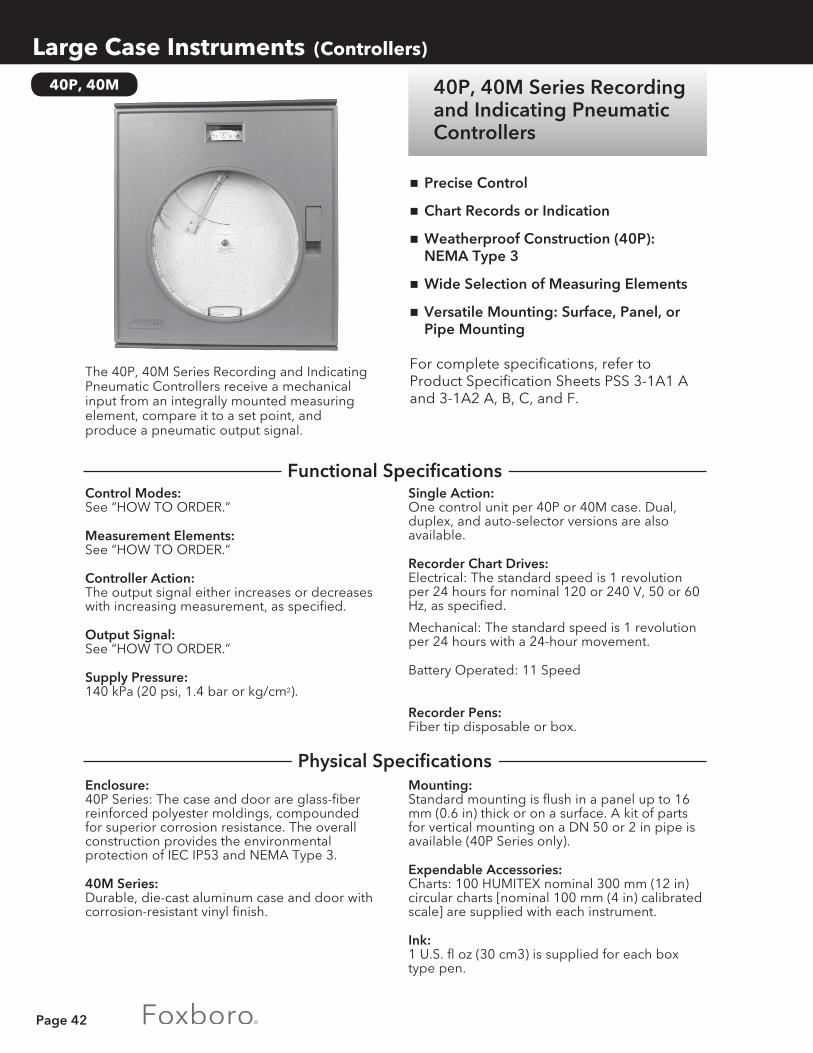
Page 42
40P, 40M
Large Case Instruments (Controllers)
40P, 40M Series Recording and Indicating Pneumatic Controllers
The 40P, 40M Series Recording and Indicating Pneumatic Controllers receive a mechanical input from an integrally mounted measuring element, compare it to a set point, and produce a pneumatic output signal.
Mounting:Standard mounting is flush in a panel up to 16 mm (0.6 in) thick or on a surface. A kit of parts for vertical mounting on a DN 50 or 2 in pipe is available (40P Series only).
Expendable Accessories:Charts: 100 HUMITEX nominal 300 mm (12 in) circular charts [nominal 100 mm (4 in) calibrated scale] are supplied with each instrument.
Ink:1 U.S. fl oz (30 cm3) is supplied for each box type pen.
Single Action:One control unit per 40P or 40M case. Dual, duplex, and auto-selector versions are also available.
Recorder Chart Drives:Electrical: The standard speed is 1 revolution per 24 hours for nominal 120 or 240 V, 50 or 60 Hz, as specified.
Mechanical: The standard speed is 1 revolution per 24 hours with a 24-hour movement.
Battery Operated: 11 Speed
Recorder Pens:Fiber tip disposable or box.
Enclosure:40P Series: The case and door are glass-fiber reinforced polyester moldings, compounded for superior corrosion resistance. The overall construction provides the environmental protection of IEC IP53 and NEMA Type 3.
40M Series:Durable, die-cast aluminum case and door with corrosion-resistant vinyl finish.
Control Modes:See “HOW TO ORDER.”
Measurement Elements:See “HOW TO ORDER.”
Controller Action:The output signal either increases or decreases with increasing measurement, as specified.
Output Signal:See “HOW TO ORDER.”
Supply Pressure:140 kPa (20 psi, 1.4 bar or kg/cm2).
nPrecise Control
nChart Records or Indication
nWeatherproof Construction (40P): NEMA Type 3
nWide Selection of Measuring Elements
nVersatile Mounting: Surface, Panel, or Pipe Mounting
For complete specifications, refer toProduct Specification Sheets PSS 3-1A1 A and 3-1A2 A, B, C, and F.
Functional Specifications
Physical Specifications

Page 43
Large Case Instruments (Controllers)
40P, 40M
Repeatability:0.25% of calibrated span.
Accuracy:See Measurement Element selected.
Batch:For batch control.
Type 70 Contacts:For electrical contact output. Refer to Page 57.
External Connection to Integral Bellows.
Pneumatic Set:For remote set point adjustment.
External Manual Set Point Knob.
Ratio:Maintains ratio between uncontrolled and controlled variable.
Performance Specifications
Optional Features
How to Order1) SPECIFY MODEL NUMBER:
40P or 40M ___ - ___ ___ ___ - ___ ___ ___ ___ ___ / ____________ AFunction: Recording ...........................................................R Indicating ........................................................... N
Action: Single (One control unit actuated by one
measuring element. Control will apply to first listed element.) ........................................................ A
Control: On/Off ..................................................................................1 Full proportional 0.5 to 200% ..........................................2 Full proportional plus derivative 0.01 to 50 minutes ....3 Full proportional plus integral (reset) 0.01 to
50 minutes per repeat. .................................................4 Full proportional plus integral (reset) plus derivative ...5 Narrow band proportional 0.5 to 25% or 1.0 to 50% ..6
Automatic/Manual Internal Transfer Switching: Without internal regulator, without transfer switch (a) .......... J 2-position nozzle seal switch (b) .............................................. L Balanceable automatic/manual unit - right (b) .......................N Balanceable automatic/manual unit - left (b) .........................P
Output Signal and Gauge: 20 to 100 kPa signal, 150 kPa gauge ...............................................5 3 to 15 psi signal, 22 psi gauge ........................................................2 0.2 to 1.0 bar signal, 1.5 bar gauge .................................................6 0.2 to 1.0 kg/cm2 signal, 1.5 kg/cm2 gauge.....................................4
Mounting: Flush (c) .........................................................................................................F Pipe (c), (d) ....................................................................................................P Surface (c) ......................................................................................................S Yoke. 40P Series available with Type 37 Element only ..........................Y(a) Available with Control code 1 only. (b) Not available with Control code 1. (c) Not available with 40P Series with Type 37 Element. (d) Not available with 40M Series.
HOW TO ORDER Continued on Next Page.

Page 44
40P, 40M
Large Case Instruments (Controllers)
How to Order (continued)1) SPECIFY MODEL NUMBER:
40P or 40M ___ - ___ ___ ___ - ___ ___ ___ ___ ___ / ____________ AChart Drive or Scale: Electrical - 24 h rotation, 120 V, 60 Hz (options available) ............................. E Mechanical - 24 h rotation and wind (options available)................................M Sector ....................................................................................................................N
Pens or Pointers: 1 pen or pointer ............................................................................................................1 2 pens or pointers .........................................................................................................2 3 pens .............................................................................................................................3
Pen Type or Scale Type: Fiber tip disposable ...............................................................................................................F Box ......................................................................................................................................B Single range scale ..................................................................................................................S Double range scale ............................................................................................................... D
Elements: (Refer to Pages 48-56 for Element Descriptions) Type 37 (a) .........................................................................................................................................DE-A, B Absolute pressure bellows ...............................................................................................................PA-CA Receiver .................................................................................................................................................. PC Absolute pressure double spiral ..................................................................................................... PA-MA Pressure helical ............................................................................................................................. PB-M, PB-AA Pressure spiral .................................................................................................................................... PB-BA Pressure bellows ............................................................................................................................ PB-CA, CC Diaphragm .......................................................................................................................................PB-DF, PF Stainless long helical ......................................................................................................................... PB GA Temperature ................................................................................................................................... TA-1A, 2A, 2B, 3B Electronic servo ...................................................................................................................................... E(a) Only one per instrument.
2) SPECIFY MEASUREMENT RANGE __________________________________________________3) SPECIFY CONTROLLER ACTION ___________________________________________________4) SPECIFY OPTIONAL FEATURES ____________________________________________________5) SPECIFY INFORMATION FOR INSTRUMENT TAG ___________________________________

Page 45
Large Case Instruments (Controllers)
43AP
The 43AP Series Pneumatic Indicating Controllers continuously indicate and control pressure, vacuum, temperature, or flow.
43AP Series PneumaticIndicating Controllers
Controller Action:Output signal either increases or decreases with increasing measurement, as specified; action is reversible in the field.
Supply Pressure:140 kPa, 20 psi, 1.4 bar or kg/cm2.
Output Signal:See “HOW TO ORDER.”
Ambient Temperature Limits:-40 and +80°C (-40 and +180°F).
Repeatability:0.2% of calibrated span.
nWide Selection of Direct Connected Measurement Elements
nBroad Choice of Control Modes • On/off, proportional, proportional plus
derivative, proportional plus integral (reset), proportional plus integral (reset) plus deriva-
tive, differential gap, and automatic shutdown
nInternal Bumpless Auto/Manual Transfer • Smooth internal switching
nWeatherproof • Glass-fiber reinforced case, gasketed door • NEMA Type 3 protection
nAccuracy Unaffected by Mounting • Measurement element and control unit
mounted on rigid steel plate
For complete specifications, refer to Product Specification Sheet PSS 3-1B3 A.
Control Modes:See “HOW TO ORDER.”
Measurement Elements:See “HOW TO ORDER.”
Output Gauge:0 to 200 kPa, 0 to 30 psi, or 0 to 2 bar or kg/cm2, as specified.
Set Point Adjustment:By means of a knob mounted inside the case.
Accuracy (When used with the elements as listed under “HOW TO ORDER”): ±0.5% of calibrated span.
Pipe: a kit of parts to fit a DN 50 or 2 in vertical pipe.
Yoke: a kit of parts to fit a vertical DN 50 or 2 in pipe stub. This mounting scheme is designed specifically for controllers having rear-mounted differential pressure elements.
Mounting:Panel, surface, pipe, or yoke. Panel: Flush in a panel up to 16 mm (0.6 in) thick.
Surface: suitable for all controllers having internally mounted elements. This mounting is not available with heavy duty helical elements. (These elements extend through the back of the case.)
Functional Specifications
Performance Specifications
Physical Specifications

Page 46
43AP
Large Case Instruments (Controllers)
1) SPECIFY MODEL NUMBER: 43AP- ___ ___ ___ ___ - ___ / ______________
Mounting: Field (pipe or yoke) ............................................................................. F Panel or surface ................................................................................... P
Control: On/Off .......................................................................................................... A1 Proportional 4 to 400% ............................................................................. A2 Proportional plus derivative 0.05 to 50 minutes .................................... A3 Proportional plus integral (reset) 0.01 to 50 minutes per repeat ........ A4 Proportional plus integral (reset) plus derivative .................................. A5 Differential gap 1 to 100% ........................................................................ A7 Automatic shutdown .................................................................................. A8
Output Signal and Gauge: 20 to 100 kPa signal, 200 kPa gauge ................................................................ 5 3 to 15 psi signal, 30 psi gauge ......................................................................... 2 0.2 to 1.0 bar signal, 2 bar gauge ..................................................................... 6 0.2 to 1.0 kg/cm’ signal, 2 kg/cm2 gauge ........................................................ 4
Automatic/Manual Internal Transfer Switching: None ............................................................................................................................N Bumpless with 2-position switch, balance gauge, regulator ................................. C 2-position nozzle seal switch for manual control .....................................................D
Optional Suffix: Remote pneumatic set point (not available with pressure element codes PA-CA, PA-CC, PB-CA, PB-GA, PB-PF; servo element code E; Type 70 Contacts; or options ECRB and “BATCH”) .................................................... P
HOW TO ORDER Continued on Next Page.
Batch:For batch control.
Vent Connection.
External Phenolic Nameplate.
Glass Window in Door.
Stainless Steel Data Plate.
Tamperproof Door Knob.
Integral Air Supply Set.
Type 70 Contacts:For electrical contact output. Refer to Page 57.
Control Valve Mounting.
External Connection to Integral (Reset) Bellows (ECRB) .
External Set Point.
Scale:Black markings on a white background, sector-shaped with nominal effective length of 150 mm (6 in). Refer to Chart and Dial Catalog 600 for available ranges.
Enclosure:The case and door are glass-fiber reinforced polyester moldings, compounded for superior corrosion resistance. The door has a shatterproof polycarbonate window, ultraviolet-resistant. The overall construction is weatherproof, meets IEC IP53, and provides the environmental protection of NEMA Type 3.
How to Order
Optional Features
Physical Specifications (continued)
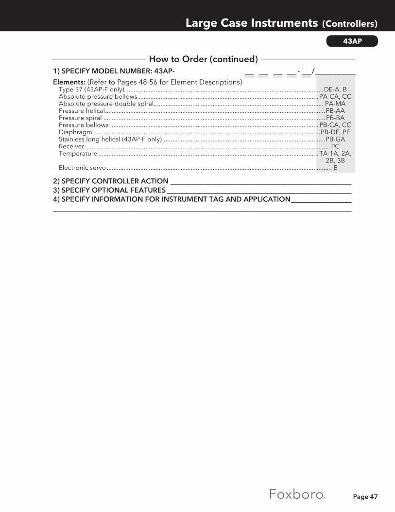
Page 47
Large Case Instruments (Controllers)
43AP
1) SPECIFY MODEL NUMBER: 43AP- ___ ___ ___ ___ - ___ / ______________
Elements: (Refer to Pages 48-56 for Element Descriptions) Type 37 (43AP-F only) ......................................................................................................................DE-A, B Absolute pressure bellows ...........................................................................................................PA-CA, CC Absolute pressure double spiral ..................................................................................................... PA-MA Pressure helical ...................................................................................................................................PB-AA Pressure spiral .................................................................................................................................... PB-BA Pressure bellows ............................................................................................................................ PB-CA, CC Diaphragm .......................................................................................................................................PB-DF, PF Stainless long helical (43AP-F only) .................................................................................................PB-GA Receiver .................................................................................................................................................. PC Temperature ................................................................................................................................... TA-1A, 2A, 2B, 3B Electronic servo ...................................................................................................................................... E
2) SPECIFY CONTROLLER ACTION ___________________________________________________3) SPECIFY OPTIONAL FEATURES ____________________________________________________4) SPECIFY INFORMATION FOR INSTRUMENT TAG AND APPLICATION _____________________________________________________________________________________________________
How to Order (continued)

Page 48
P417
Large Case Instruments (Controllers)
P417 Pneumatic Field Controller
nSame basic instrument for field / panel mounting
nAluminium die-cast housing, with lock, protection class IP 54 (IP 65)nWell-established cross-bellows control systemnSet point, measured value and output indicationnVersions for master and slave controlnPush-buttons for manual / auto transfernBumpless manual / auto transfernLimiting of controller outputnExternal feedbacknField controller changeover relaynMode switchingnOperating point set internally / externallynFunction altered by interchanging standard
modulesnService label
Complete instrumentP417pneumatic controllers are complete pneumatic control stations and, in conjunction with transmitters, are suitable for all control applications in process plants, particularly for field mounting. Field controllers are also available without an indicator.
Measured value x ........... 0.2 to 1.0 bar /Set point w ...................... 3 to 15 psi /Output y ........................... 20 to 100 kPaSupply air ......................... 1.4 ± 0.1 bar / 20 ±1.4 psi / 140 ± 10 kPaInherent air consumption 1) 2) ............ ≤ 500 l / hr
HousingFront finish ....................... door enamelled grey to RAL 7000, with lockService label .................... 50 x 13mm, replaceable
MaterialsHousing, with door ........ aluminium, with DD enamel, grey RAL 7000Connection block for wall / panel mounting ... aluminium, with DD enamel, grey RAL 7000Measuring elements.. .... copper-berylliumOther internal components .................... aluminium, brass, galvanized and passivated steel
Double indicator for x and wError limit ......................... < 1%
Indicator for output signalIndication range ............. 0 to 1.2 bar / 18 psi / 120 kPaError limit ......................... < 1.6%
Signal generators for set point and output signalOutput adjustable. ......... 0 to 1.2 bar / 18 psi / 120 kPaSupply air dependency. ≤ 0.25 % / 0.1 barAir consumption ............. ≤ 100 l / hr per signal generator
} Manual-Auto switchType ....................................push-buttons
Controller sectionSystem ................................cross-belowsControl modes ..................P, PD, PI, PIDOperating point P / PD controller ............................set pneumatically, either internally or externallyProportional band Xp ......5 to 400%and higherGain Kp ...............................20 to 0.25 and lowerReset time Tn .....................0.03 to 50minDerivative time Tv .............0.03 to 20minTracking error1) .................≤ 0.7 %Alignment offset1) ............≤ 0.7 %Supply air dependency1) ...≤ 0.2 % / 0.1 barTemperature effect1) .......≤ 0.2 % / 10 KSensitivity1) .........................≤ 0.1 %Startup relay ......................for bridging time function “manual”Tracking relay ....................for bumplessmanual - auto transfer, even with deviationMode switching:— PI-switching ....................reset bellows loading input, internal or external— P / PI-switching ..............switchingwith external signalExternal feedback ............external pressure applied to feedback bellows R+
Additional equipmentMin- /Max-limiting ............formin. ormax. limiting of “R” or “yA + R” limit value settable to 0.2 to 0.6 bar or 0.6 to 1.0 bar
1) Measured at Xp = 100 % resp. with PI controller2) Master version

Page 49
Large Case Instruments (Controllers)
How to Order
Code P417-541PID Controller with indicator, Tn and Tv startup relays
Panel mounting
Pneumatic Field Controller P417 Version Master controller with signal generator for output signal ........................................ -1 Slave controller with signal generator for output signal ........................................... -2 Master controller without signal generator for output signal .................................. -3 Slave controller without signal generator for output signal .................................... -4 Field controller with indicator (5 pipe) ......................................................................... -5 Field controller without indicator (5 pipe) ................................................................... -6
HOW TO ORDER Continued on Next Page.

Page 50
P417
Large Case Instruments (Controllers)
How to Order (continued)Control mode and equipment P Operating point internally .......................................................................................................................1 P Operating point externally (a) ...............................................................................................................12 PD with Tv-startup relay O.P. internally (b) .............................................................................................21 PD with Tv-startup relay O.P. externally (b) ............................................................................................22 PI with Tn-startup relay (d) ..........................................................................................................................31 PI with Tn-startup relay and tracking relay (d) .......................................................................................32 PI with PI-switch, YF internally (a) ...............................................................................................................3 PI with PI-switch, YF externally (b) .............................................................................................................34 PI with PI-switch,Tn-startup relay, YF internally (b) ................................................................................35 PI with PI-switch,Tn-startup relay, YF externally (b) ...............................................................................36 PI externally feedback with Tn-startup relay (b) .....................................................................................37 PI Auto-Selector-Master controller with Tn-startup relay (b) ...............................................................38 PI Auto-Selector-Slave controlle with Tn-startup relayr (b) ..................................................................39 PID with Tn-, Tv-startup relay (d) ................................................................................................................41 PID with Tn-, Tv-startup relay and tracking relay (d) ..............................................................................42 PID with PI-switch, YF internally (b) ...........................................................................................................43 PID with PI-switch, YF externally (b) ..........................................................................................................44 PID with PI-switch, Tn-startup relay, YF internally (b) .............................................................................45 PID with PI-switch, Tn-, Tv-startup relay, YF externally (b) .....................................................................46 PID externally feedback with Tn-,Tv-startup relay (b) ............................................................................47 PID Auto-Selector-Master controller with Tn-, Tv-startup relay (b) .....................................................48 PI Auto-Selector-Slave controller with Tn-, Tv-startup relay (b) ...........................................................49 P / PI with Tn-startup relay, O.P. internally (b) ..........................................................................................51 P / PI with Tn-startup relay, O.P. externally (b) .........................................................................................52 P / PI with Tn-startup relay, tracking relay Operating point internally (b)..............................................53 P / PI with Tn-startup relay, tracking relay Operating point externally (b) .............................................54 P / PI with remote switching,Tn-startup relay Operating point internally (b) .......................................55 P / PI with remote switching,Tn-startup relay Operating point externally (b) ......................................56 P / PI / PID with Tn-startup relay, O.P.internally (b) .....................................................................................61 P / PI / PID with Tn-,Tv-startup relay, O.P.externally (b) ..............................................................................62 P / PI / PID with Tn-startup relay,tracking relay Operating point internally (b) ....................................63 P / PI / PID with Tn-startup relay,tracking relay Operating point externally (b). ...................................64Indicating Range (Scale) for X and W 0 - 100% linear (h) ....................................................................................................................................................... A to be specified (acc.standard list) (h) ...................................................................................................................... B without indicator (k) ....................................................................................................................................................CSignal Range 0.2-1.0bar ................................................................................................................................................................................1 3-15psi ...................................................................................................................................................................................2 20-100kPa ................................................................................................................................................................................3Indicating Range for output signal 0-1.2bar ..............................................................................................................................................................................................1 0-18psi ..............................................................................................................................................................................................2 0-120kPa .............................................................................................................................................................................................3Type of mounting Wall / Pipe mounting, pneum.conn. 1/4 -18 NPT ................................................................................................................................ A Wall / Pipe mounting, pneum.conn. G 1/4 ........................................................................................................................................... B Panel mounting, pneum.conn. 1/8 -27 NPT .......................................................................................................................................... COptions min. limitation of YA and R (for P-controller YA only) .....................................................................................................................................-A min. limitationofR (b) (e) .......................................................................................................................................................................................-B max. limitation of YA and R (for P-controller YA only) ....................................................................................................................................-C max. limitationofR (b) (e) ......................................................................................................................................................................................-D min.- max. limitation of YA and R (for P-controller YA only) (b) (f) ................................................................................................................-E Kit for pipe mounting .......................................................................................................................................................................................... -M Plug for test jack (O.P. for P-, PD-controller) ..................................................................................................................................................... -S Protection class IP 65 (for mounting type A, B) ............................................................................................................................................... -P Tag.No. Labeling with inscription ...................................................................................................................................................................... -LCertificates EN 10204-2.1 (DIN 50 049-2.1) ......................................................................................................................................................................... -1
NOTES(a) Only available with Version -1, -2, -3, -4(b) Only available with Version -1, -2(c) Only available with Version -3, -4
(d) Only available witht Version -1,-2,-5,-6(e) Only available with control mode 31, 32, 41, 42(f) Only available with control mode 31, 32, 34, 36
(g On request(h) Not available with Version -6(k) Not available with Version -1, -2, -3, -4, -5

Page 51
40P, 40M
Large Case Instruments (Recorders and Indicators)
40P, 40M Series Recordersand Indicators
The 40P and 40M Series Instruments continuously record or indicate measure-ment of one or more process variables.
Expendable Accessories:Charts: 100 HUMITEX nominal 300 mm (12 in) circular charts [nominal 100 mm (4 in) calibrated scale] are supplied with each instrument.
Ink:1 U.S. fl oz (30 cm3) is supplied for each box pen.
Indicator Pointer:Sector indicators have an orange pointer and concentric indicators have a black pointer.
Indicator Scales:Black markings on white background. Refer to Chart and Dial Catalog 600 for available ranges.
Sector:The effective length is 171 mm (6.75 in).
Concentric:The effective length is 594 mm (23.4 in).
Battery Operated: 11 speed.
Ambient Temperature Limits:-30 and +60°C (-20 and +140°F).
Recorder Pens:Fiber tip disposable or box.
Enclosure:40P Series: The case and door are glass-fiber reinforced polyester moldings, compounded for superior corrosion resistance. The door has a shatterproof glass window. The overall construction provides the environmental protection of IEC IP53 and NEMA Type 3.
40M Series: Durable, die-cast aluminum case and door with corrosion-resistant epoxy powder finish.
Mounting:Standard mounting is flush in a panel up to 16 mm (0.6 in) thick or on a wall. A kit of parts for vertical mounting on a DN 50 or 2 in pipe is available as an option (40P Series only).
Cardboard Nameplate:A cardboard nameplate is supplied for displaying the chart factor.
Measurement Elements:See “HOW TO ORDER.”
Recorder Chart Drives:Electrical: The standard speed is 1 revolution per 24 hours for nominal 120 or 240 V, 50 or 60 Hz, as specified.
Mechanical: The standard speed is 1 revolution per 24 hours with a 24-hour movement.
See Measurement Element selected.
nWide Selection of Measuring Elements
nVersatile Mounting: Surface, Panel, or Pipe Mounting
nChoice of Circular Chart Recorder or either Concentric or Sector Scale Indicator
nWeatherproof Construction (40P Series): NEMA Type 3
For complete specifications, refer to Product Specification Sheets PSS 3-1A1 A and 3-1A2 A, B, C, and E.
Functional Specifications
Physical Specifications
Performance Specifications

Page 52
Large Case Instruments (Recorders and Indicators)
40P, 40M
1) SPECIFY MODEL NUMBER: 40P or 40M- ___ - ___ ___ ___ ___ ___ / ______________
Function: Circular Chart Recorder .............................................................R Sector Scale Indicator ................................................................ N Concentric Scale Indicator ........................................................ K
Internal Mechanism: Recorder - standard ............................................................................ R Indicator- sector ..................................................................................N Indicator - concentric .......................................................................... K With Type 70 Contacts (recorder or indicator) ............................... E
Mounting: Flush (a) .........................................................................................................F Pipe (a), (b) ....................................................................................................P Surface (a) ......................................................................................................S Yoke. 40P Series available with Type 37 Element only ..........................Y
Chart Drive or Scale: Electrical, 24 h rotation, 120 V, 60 Hz (options available) .............................. E Mechanical, 24 h rotation and wind (options available) ................................ M Sector scale ...........................................................................................................N Concentric scale ...................................................................................................K Battery operated (11 speed) .............................................................................XX
Pens or Pointers: 1 pen (R) or 1 pointer (N or K) .................................................................................... 1 2 pens (R) or 2 pointers (N) ......................................................................................... 2 3 pens (R)....................................................................................................................... 3 4 pens (R)....................................................................................................................... 4
Pen Type or Scale Type: Fiber tip disposable .............................................................................................................. F Box ..................................................................................................................................... B Single range scale ................................................................................................................. S Dual range scale. For 40PN and 40MN Series only. ........................................................ D
(a) Not available with 40P Series with Type 37 Element. (b) Not available with 40M Series.
HOW TO ORDER Continued on Next Page.
Indicating Scale Transparent Mounted in Instrument Door.
Plexiglass Circular Disc.
Portable Mounting.
Incandescent Type Internal Illumination.
Bakelite Nameplate.
Flush Door Lock.
Segmental Indicating Scale.
How to Order
Optional Features

Page 53
40P, 40M
Large Case Instruments (Recorders and Indicators)
1) SPECIFY MODEL NUMBER: 40P or 40M- ___ ___ ___ ___ ___ - ___ / ______________
Elements: (Refer to Pages 48-56 for Element Descriptions) Type 37 (yoke mounting only) (a) ...................................................................................................DE-A, B Absolute pressure bellows ...............................................................................................................PA-CA Receiver .................................................................................................................................................. PC Absolute pressure double spiral ..................................................................................................... PA-MA Pressure helical ............................................................................................................................. PB-M, PB-AA Pressure spiral .................................................................................................................................... PB-BA Pressure bellows ............................................................................................................................ PB-CA, CC Diaphragm .......................................................................................................................................PB-DF, PF Stainless long helical .........................................................................................................................PB-GA Temperature ................................................................................................................................... TA-1A, 2A, 2B, 3B Electronic servo ...................................................................................................................................... E Relative humidity (b) ...........................................................................................................................MA-K(a) Only one per instrument.(b) Not available with 40P Series.
2) SPECIFY OPTIONAL FEATURES ____________________________________________________3) SPECIFY INFORMATION FOR INSTRUMENT TAG ___________________________________
How to Order (continued)

Page 54
Large Case Instruments (Recorders and Controllers)
43APG
Case:Glass-fiber reinforced, gray polyester molding.
Enclosure Classification:Meets IEC IP53 and provides the environmental protection of NEMA Type 3.
Door:Hinged, glass-fiber reinforced phenylene oxide molding with blue polyurethane finish. The clear polycarbonate window is ultraviolet-resistant and shatterproof.
Refer to Foxboro.
WARNING:EXPLOSION HAZARD CAN RESULT FROM USE OF NATURAL GAS AS SUPPLY. INSTRUMENT LOCATION MUST BE PROPERLY CLASSIFIED PER NFPA-70. TOXICITY HAZARD CAN RESULT FROM USE OF SUPPLY GAS CONTAINING HYDROGEN SULFIDE (H2S). AREA MUST BE VENTILATED OR BREATHING APPARATUS USED. REFER TO Ml 011-111.
Repeatability: Less than 0.2% of span.
Dead Band: Less than 0.1 % of span.
Hysteresis: ±1 % of output span.
n43APG Series Controllers: • NACE compliant element materials available. • Low air consumption and internal corrosion resistance means the 43APG can be operated directly from the process gas • Wide choice of measurement elements
nGlass-fiber reinforced case with gasketed door provides NEMA Type 3 protection.
For complete specifications, refer to Product Specification Sheets PSS 7-3C3 A and B.
Measurement Elements and Configurations:See “HOW TO ORDER.”
Controller Output Signal and Supply Pressure:
(a) Not applicable to the 43APG Series Controllers.
Recorder Accuracy:Spans less than 12:5 kPa, 50 inH20, 125 mbar ΔP and all compound ranges: ±0.50% of span.
Controller (less element) Accuracy:
43APG Series Controllers provide precise indication and control of flow, pressure, vacuum, and temperature.
Output Signal Supply Pressure
20 to 100 kPa (a) 140 kPa (a) 3 to 15 psi 20 psi 0.2 to 1.0 bar or kg/cm2 (a) 1.4 bar or kg/cm2 (a)
Oil & Gas Industry Flow Recorders and Controllers
Physical Specifications
Optional Features
Functional Specifications
Performance Specifications

Page 55
43APG
Large Case Instruments (Recorders and Controllers)
1) SPECIFY MODEL NUMBER: 43APG- ___ ___ ___ ___ - ___ / ______________ 2
Mounting: Field ................................................................................................... F Panel or Surface .................................................................................. P
Control: On-Off .......................................................................................................... A1 Proportional 4 to 400% ............................................................................. A2 Proportional plus Derivative 0.05 to 50 minutes ................................... A3 Proportional plus Reset (Integral) 0.01 to 50 minutes per repeat ....... A4 Proportional plus Integral plus Derivative .............................................. A5 Differential Gap 1 to 100% ....................................................................... A7
Output Signal and Gauge: 3 to 15 psi signal, 30 psi gauge ......................................................................... 2
Automatic/Manual Internal Transfer Switching: Bumpless with 2-position switch, balance gauge, regulator ................................. C 2-position nozzle seal switch for manual control .....................................................D None ............................................................................................................................N
Optional Suffix: Remote Pneumatic Set Point (not available with element code PA-CA, PA-CC, PB-PF, or PB-GA) ................................................................................... P
Element: (Select one, refer to Pages 48-56 for Element Descriptions) Type 37 (43APG-F only) ................................................................................................................ DE-A (a), B Absolute pressure bellows ...........................................................................................................PA-CA, CC Receiver .............................................................................................................................................. PC-OC Absolute pressure double spiral ..................................................................................................... PA-MA Pressure helical ............................................................................................................................. PB-AA, AM (b) Pressure spiral .............................................................................................................................. PB-BA, BM (b) Pressure bellows ............................................................................................................................ PB-CA, CC Diaphragm .......................................................................................................................................PB-DF, PF Stainless long helical (43APG-F only) ..............................................................................................PB-GA Temperature (c) .............................................................................................................................. TA-1A, 2A, 2B, 3B(a) Available in NACE compliant version. (b) Element codes PB-AM and PB-BM comply with NACE Standard MR-01-75. (c) Available with AISI Type 316 stainless steel tubing only.
2) SPECIFY SCALE FROM CHART AND DIAL CATALOG 600 OR REFER TO FOXBORO _______________________________________________________________________
3) SPECIFY CALIBRATED RANGE _____________________________________________________4) SPECIFY CONTROL ACTION (FIELD REVERSIBLE) ___________________________________5) SPECIFY INFORMATION FOR INSTRUMENT TAG ___________________________________
How to Order
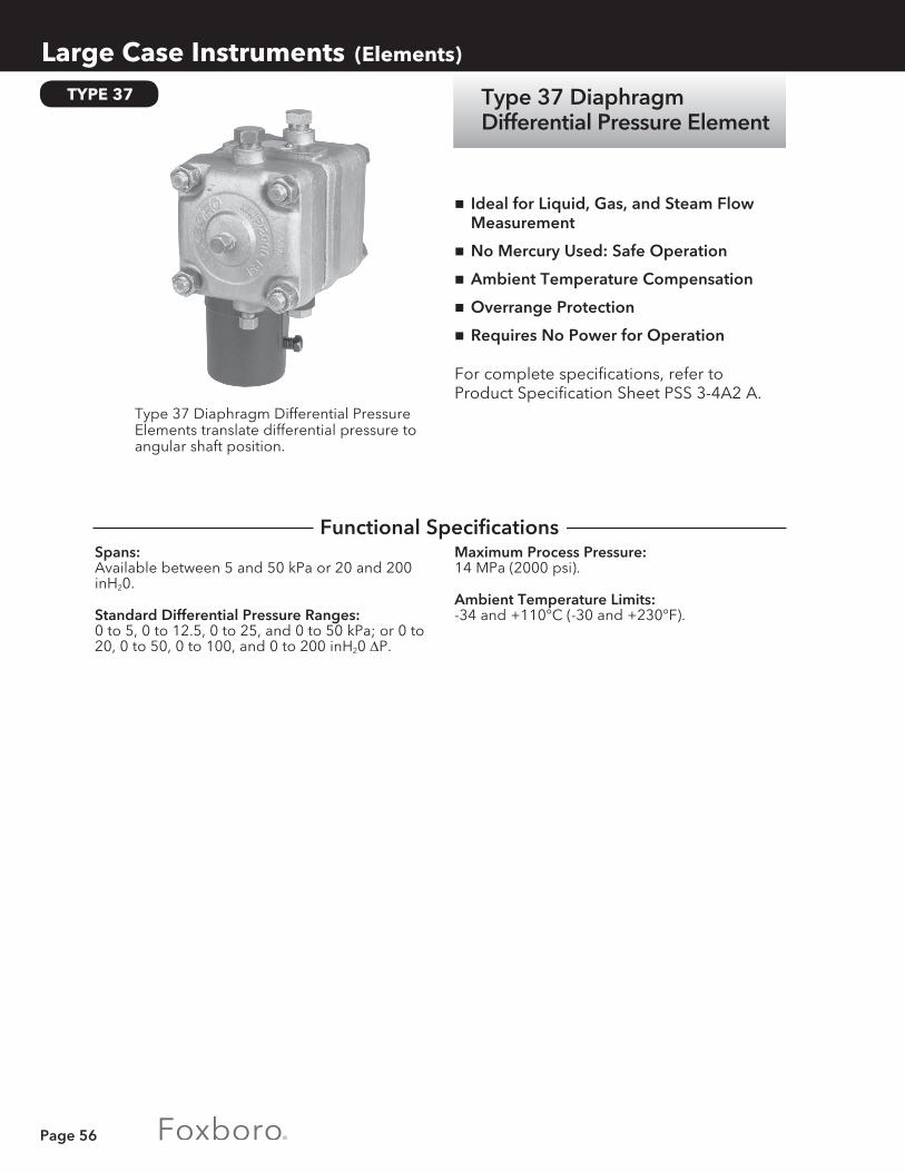
Page 56
Large Case Instruments (Elements)
TYPE 37
Maximum Process Pressure:14 MPa (2000 psi).
Ambient Temperature Limits:-34 and +110°C (-30 and +230°F).
nIdeal for Liquid, Gas, and Steam Flow Measurement
nNo Mercury Used: Safe Operation
nAmbient Temperature Compensation
nOverrange Protection
nRequires No Power for Operation
For complete specifications, refer to Product Specification Sheet PSS 3-4A2 A.
Spans:Available between 5 and 50 kPa or 20 and 200 inH20.
Standard Differential Pressure Ranges:0 to 5, 0 to 12.5, 0 to 25, and 0 to 50 kPa; or 0 to 20, 0 to 50, 0 to 100, and 0 to 200 inH20 ΔP.
Type 37 Diaphragm Differential Pressure Elements translate differential pressure to angular shaft position.
Functional Specifications
Type 37 Diaphragm Differential Pressure Element

Page 57
PRESSURE MEASURING ELEMENTS
Large Case Instruments (Elements)
Pressure Measuring Elements measure gauge and absolute pressure and actuate recorders, indicators, controllers, and transmitters.
Copper-Nickel-Manganese (Cu-Ni-Mn) Alloy.
K-Monel.
Element Materials:AISI Type 316 ss (316 ss).
Bronze or Brass.
Oxygen Service Preparation:Available for 316 ss spirals and 316 ss helicals. Copper bearing brazing material will be in contact with process.
Overrange Protection, Underrange Protection:Provides protection to the linkage and pointer, not the pressure element.
Accuracy:Better than ±0.5%.
nWide variety of element types, materials, and pressure ranges
nDurable and dependable for long service life
For complete specifications, refer to Product Specification Sheet PSS 3-2A1 A.
Performance Specifications
Physical Specifications
Optional Features
Pressure MeasuringElements
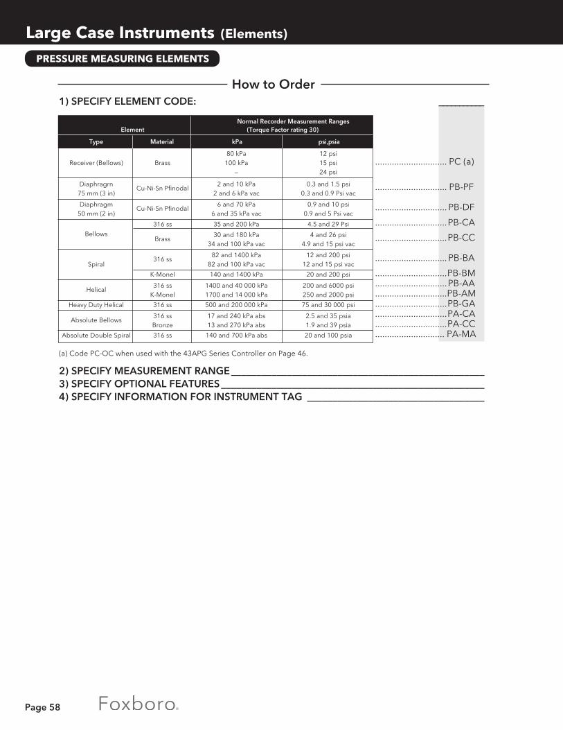
Page 58
Large Case Instruments (Elements)
PRESSURE MEASURING ELEMENTS
1) SPECIFY ELEMENT CODE: ___________
.............................. PC (a)
.............................. PB-PF
.............................. PB-DF
..............................PB-CA
..............................PB-CC
.............................. PB-BA
..............................PB-BM ..............................PB-AA ..............................PB-AM ..............................PB-GA ..............................PA-CA ..............................PA-CC ............................. PA-MA
(a) Code PC-OC when used with the 43APG Series Controller on Page 46.
2) SPECIFY MEASUREMENT RANGE __________________________________________________3) SPECIFY OPTIONAL FEATURES ____________________________________________________4) SPECIFY INFORMATION FOR INSTRUMENT TAG ___________________________________
Normal Recorder Measurement Ranges Element (Torque Factor rating 30)
Type Material kPa psi,psia
80 kPa 12 psi Receiver (Bellows) Brass 100 kPa 15 psi
— 24 psi
Diaphragrn Cu-Ni-Sn Pfinodal
2 and 10 kPa 0.3 and 1.5 psi 75 mm (3 in) 2 and 6 kPa vac 0.3 and 0.9 Psi vac
Diaphragm Cu-Ni-Sn Pfinodal
6 and 70 kPa 0.9 and 10 psi 50 mm (2 in) 6 and 35 kPa vac 0.9 and 5 Psi vac
316 ss 35 and 200 kPa 4.5 and 29 Psi
Bellows Brass
30 and 180 kPa 4 and 26 psi 34 and 100 kPa vac 4.9 and 15 psi vac
316 ss
82 and 1400 kPa 12 and 200 psi Spiral 82 and 100 kPa vac 12 and 15 psi vac
K-Monel 140 and 1400 kPa 20 and 200 psi
Helical
316 ss 1400 and 40 000 kPa 200 and 6000 psi K-Monel 1700 and 14 000 kPa 250 and 2000 psi
Heavy Duty Helical 316 ss 500 and 200 000 kPa 75 and 30 000 psi
Absolute Bellows
316 ss 17 and 240 kPa abs 2.5 and 35 psia Bronze 13 and 270 kPa abs 1.9 and 39 psia
Absolute Double Spiral 316 ss 140 and 700 kPa abs 20 and 100 psia
How to Order

Page 59
Filled Thermal System Elements consist of sensor, connection tubing, and mechanical element.
Class IIA:A thermal system that is evacuated and partially filled with a volatile liquid, such as methyl chloride (CL), ether (ET), butane (BU), or toluene (T).
Class IIIB:A gas system that is filled under pressure with purified nitrogen.
Thermal System Types:
Class IA:A thermal system that is completely filled with an incompressible liquid under pressure. The system is fully compensated for ambient temperature variations at case and along the tubing.
Standard Ranges, Standard Spans and Range Limits:
nDependable • Field-proven performance
nNonelectric • Continuous operation, even with power
failure
nSafe • Suitable for Class I, Division 1 hazardous
locations
For complete specifications, refer to Product Specification Sheet PSS 3-3A1 A.
THERMAL ELEMENTS
Large Case Instruments (Elements)
CLASS IA CLASS IIA CLASS IIIB Standard
X Length Range Limits Standard Standard Range Limits
Spans Minimum Maximum Ranges (Fills) Spans Minimum Maximum °C mm in °C °C °C °C °C °C
25 122 4.8 13 120 38 to 105 (BU) 100 -40 170 50 69 2.7 -15 200 105 to 150 (ET) 150 -15 400 75 53 2.1 -38 200 50 to 205 (T) 200 -15 500 100 43 1.7 -63 200 38 to 150 (ET) 250 -15 500 150 36 1.4 -73 250 50 to 250 (T) 300 -15 500 200 30 1.2 -73 260 400 -15 500 250 28 1.1 -73 260 500 -15 500 °F mm in °F °F °F °F °F °F 50 112 4.4 50 250 100 to 180 (CL) 150 -50 240 100 69 2.7 0 400 100 to 220 (BU) 200 -50 425 150 51 2.0 -50 400 100 to 250 (BU) 300 0 825 200 43 1.7 -100 400 100 to 270 (BU) 400 0 1000 250 36 1.4 -100 400 100 to 300 (ET) 500 0 1000 300 33 1.3 -100 500 100 to 350 (ET) 600 0 1000 400 28 1.1 -100 500 100 to 400 (T) 700 0 1000 500 25 1.0 -100 500 200 to 500 (T) 800 0 1000 1000 0 1000
Filled Thermal System Elements
Functional Specifications

Page 60
Large Case Instruments (Elements)
Thermowells:Refer to Page 35.
Mounting Flanges.
Special Purpose Sensors:Preformed capillary, coated type, etc.
J = 450mm(18in).
X = 100 mm (4 in) for Class IIA and 150 mm (6 in) for Class IIIB systems. For Class IA systems, X is governed by sensor diameter and measure-ment span. See table under “FUNCTIONAL SPECIFICATIONS” on previous page.
U = (minimum) = X + 50 mm (2 in).
U = (maximum) = X + 380 mm (15 in).
B = 1/2, 3/4, or 1 NPT external threads as specified for Class IA or IIA systems and 1 NPT external threads for Class IIIB systems.
Y = 9.53 mm (3/8 in) for Class IA and IIA, 22.26 mm (7/8 in) for Class IIIB.
Alternative Thermal Systems:
a) Longer capillary lenghts and types.
b) Other ranges and spans.
c) Sanitary fittings.
d) IIB system.
Sensor Type:Adjustable union, bendable extension.
Sensor Dimensions:X = Sensitive portion length.U = Insertion length.J = Extension length.B = Bushing thread type and size.Y = Sensor diameter.
Connecting Tubing:1.5, 4.5, or 7.5 m (5, 15, or 25 ft) flexible stainless steel over stainless capillary.
Class IIIB:±0.5% of calibrated span for spans up to 330°C (600°F).±0.75% of upper range value for upper range value above 330°C (600°F). ±0.75% of lower range value for lower range value below 45°C (-50°F).
Accuracy:Class IA:±0.5% of calibrated span for spans up to 215°C (400°F).±0.75% of calibrated span for spans between 215 and 330°C (400 and 600°F).
Class IIA:±0.5% of calibrated span over upper 2/3 of scale.
THERMAL ELEMENTS
Optional Features
Performance Specifications
Physical Specifications

Page 61
1) SPECIFY BASE INSTRUMENT BY MODEL NUMBER (Recorder, Indicator, Controller, Transmitter) __________________________________________________________
2) SPECIFY CLASS/TUBING/SENSOR CODES IA Liquid Filled: TA-1A/D-FS-SS/4542-J18 _____________________________________ IIA Vapor Filled: TA-2A/S-FS-SS/2542-J18 _____________________________________ IIIB Gas Filled: TA-3B/S-FS-SS/3542-J18 _______________________________________3) SPECIFY CALIBRATED RANGE (must meet requirements of table under
“Functional Specifications” on Page 51) ____________________________________________4) SPECIFY NORMAL WORKING TEMPERATURE _____________________________________5) SPECIFY AMBIENT TEMPERATURE AT CASE AND ALONG TUBING _________________6) SPECIFY SENSOR DISTANCE ABOVE OR BELOW CASE (Class IIA systems only) ______7) SPECIFY ANTICIPATED “U” DIMENSION (insertion length) __________________________8) SPECIFY BUSHING THREAD SIZE “B” DIMENSION; SPECIFY 1/2, 3/4, OR
1 NPT FOR IA OR IIA SYSTEMS, 1 NPT FOR IIIB SYSTEMS __________________________9) SPECIFY OPTIONAL FEATURES __________________________________________________10) SPECIFY INFORMATION FOR INSTRUMENT TAG __________________________________
Large Case Instruments (Elements)
THERMAL ELEMENTS
How to Order

Page 62
Range Sensor Codes Available Code Range mV mA °C °F K T J Q
J J T J Q J J J K K R J Q J K K J K J Q K J
K S J K S J K J K J K J K J K R R S
R J J K K S J K R K J K K J R R
K K K K K R S S
Range Sensor Codes Available Code Range mV mA °C °F M M M Q M Q Q Q Q J M Q J M J Q Q
Q J E J E E Q Q T J Q Q J E
Q
A A T J K Q J Q E J E Q Q T J Q T E Q T J Q J Q J K Q T J Q T E
J Q J Q J K Q T J K Q K Q J Q Q J K Q T J K Q T E K Q J
Large Case Instruments (Elements)
SERVO ELEMENTS
Input Impedance (mA inputs):4 to 20 mA (Range Code 21)-6.25 ohms.10 to 50 mA (Range Code 22)-2.5 ohms.
Power Required:See “HOW TO ORDER.”
nSealed Conductive Plastic Slidewire • Does not need frequent cleaning • Fast response and long life
nRFI Protected Electronics • Module may be field-mounted
ndc Torque Motor • No brushes or gears
For complete specifications, refer to Technical Information Sheet Tl 27-1a.
Standard Ranges:
Measurement Range Code Table (see “HOW TO ORDER” for description of sensor codes):
Electronic Servo Elements are used with 40P and 40M Series Recorders, Indicators, and Controllers; 43AP and 43EP Series Indicating Controllers; and 45P Series Transmitters.
01 0 to 5 02 0 to 10 03 0 to 20 04 0 to 30 05 0 to 50 06 -50 to -50 07 -100 to +50 08 0 to 75 09 -20 to +80 10 0 to 100
11 -100 to 0 12 -200 to +100 13 -100 to +100 14 50 to 100 15 -20 to +120 16 — 17 -25 to +125 18 0 to 150 19 -50 to -150 20 50 to 150
21 4 to 20 22 10 to 50 23 0 to 200 24 -100 to +200 25 100 to 200 26 0 to 250 27 -50 to +250 28 50 to 250 29 0 to 300 30 -350 to +300
31 100 to 300 32 0 to 40 33 100 to 40 34 200 to 400 35 0 to 500 36 -150 to +500 37 200 to 500 38 300 to 500
39 0 to 600 40 —
41 200 to 600 42 300 to 600 43 0 to 700 44 200 to 700 45 0 to 750 46 0 to 800 47 100 to 800 48 300 to 800 49 0 to 900 50 500 to 900
51 700 to 900 52 0 to 1000 53 500 to 1000 54 0 to 1200 55 200 to 1200 56 400 to 1200 57 0 to 1300 58 — 59 800 to 1400 60 900 to 1400
61 0 to 1500 62 500 to 1500 63 0 to 1600 64 1100 to 1600 65 1200 to 1600 66 500 to 1700 67 0 to 1800 68 0 to 2000 69 1000 to 2000 70 1200 to 2000
71 0 to 2400 72 1200 to 2400 73 0 to 2500 74 1000 to 2500 75 1500 to 2500 76 1700 to 2500
Electronic Servo Elements
Functional Specifications
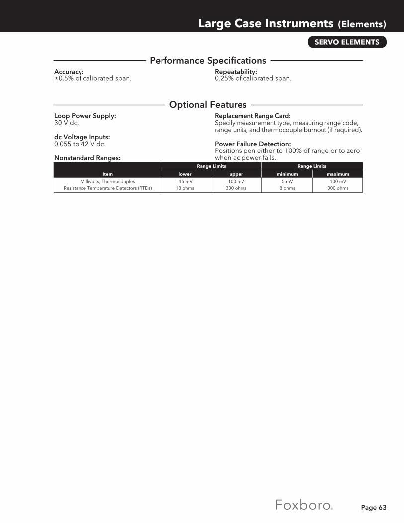
Page 63
Repeatability:0.25% of calibrated span.
Accuracy:±0.5% of calibrated span.
Replacement Range Card:Specify measurement type, measuring range code, range units, and thermocouple burnout (if required).
Power Failure Detection:Positions pen either to 100% of range or to zero when ac power fails.
Loop Power Supply:30 V dc.
dc Voltage Inputs:0.055 to 42 V dc.
Nonstandard Ranges:
SERVO ELEMENTS
Large Case Instruments (Elements)
Range Limits Span Limits Range Limits Range Limits
Item lower upper minimum maximum
Millivolts, Thermocouples -15 mV 100 mV 5 mV 100 mV Resistance Temperature Detectors (RTDs) 18 ohms 330 ohms 8 ohms 300 ohms
Performance Specifications
Optional Features

Page 64
1) SPECIFY BASE INSTRUMENT BY MODEL NUMBER: ______________ 2) SPECIFY SERVO ELEMENT: E ___ ___ ___ ___ ___
Power Supply: 120Vac ............................................................................................................................ S 220 V ac ..........................................................................................................................N 240 V ac .......................................................................................................................... P
Measurement—Sensor Type: EC/ISA T (Cu-CuNi) Thermocouple .....................................................................................T DIN 43710-77 (Cu-CuNi) Thermocouple ........................................................................... C EC/ISA J (Fe-CuNi) Thermocouple ......................................................................................J DIN 43710-77 (Fe-CuNi) Thermocouple............................................................................ D EC/ISA E (NiCr-CuNi) Thermocouple ..................................................................................E EC/ISA K (NiCr-NiAI) Thermocouple (DIN 43710-77) ...................................................... K EC/ISA R (Pt13Rh-Pt) Thermocouple ...................................................................................R EC/ISA S (Pt10Rh-Pt) Thermocouple (DIN 43710-77) .......................................................S EC/ISA B (Pt30Rh-Pt6Rh) Thermocouple ........................................................................... B dc mV .....................................................................................................................................M dc mA ..................................................................................................................................... A Platinum RTD, 100-ohm DIN Resistance ............................................................................ Q Nonstandard (including Temperature Difference) ........................................................... X
Measurement Range: Select 2-digit number from Measurement Range Code Table on Page 54. ........................ __
Range Units: Degrees Celsius ..................................................................................................................................... C Degrees Fahrenheit ................................................................................................................................F Millivolts ................................................................................................................................................... M Milliamperes ........................................................................................................................................... A
Burnout Feature (thermocouples only): Upscale action (not available with RTD) ....................................................................................................... U Downscale action (not available with RTD) .................................................................................................D None ...............................................................................................................................................................N Upscale action—Reverse Range (not available with RTD) .......................................................................... R Downscale action—Reverse Range (not available with RTD) ..................................................................... S None—Reverse Range ..................................................................................................................................... T
3) SPECIFY OPTIONAL FEATURES ____________________________________________________4) SPECIFY SENSOR (e.g., THERMOCOUPLE OR RTD) TO BE ORDERED
SEPARATELY _____________________________________________________________________5) SPECIFY INFORMATION FOR INSTRUMENT TAG ___________________________________
Large Case Instruments (Elements)
SERVO ELEMENTS
How to Order

Page 65
Type 70 Electronic Contacts
MR Series Receiver Gauges
70, MR
Large Case Instruments (Miscellaneous)
A Type 70 Electric Contact System is used to actuate external control or alarm circuits.
n Used in 40P and 40M Series Recorders, Indicators, and Controllers and 43AP Series Indicating Controllers
Rotor Units:Single or double rotor units are available, each having 3 or 5 contact segments. One segment serves as the common or collector ring contact resulting in 2, 4, or 6 segments being available for relay actuation. Contact segments are adjustable with relation to each other by micrometer adjustment screws. This relationship is not disturbed by the contact setting mechanism.
Contact Setting Mechanism:Each rotor unit is independently positioned to operate at desired values of measurement. A wide selection of setting mechanisms is available.
MR Series Receiver Gauges accept 3 to 15 psi inputs from remotely located pneumatic transmitters. A wide variety of dials and scales is available to indicate measurements in convenient engineering units.

Page 66
Panel-Mounted Pneumatic Instruments
CONSOTROL 100 is a complete family of pneumatic controllers, recorders, indicators, and auxiliary devices.
These instruments can handle the special requirements of virtually any application — from simple single control loops to interrelated multivariable systems.
Each CONSOTROL 100 unit is perfectly matched with other foxboro pneumatic instruments — including transmitters, valves, and accessories.
And they are engineered to fit into control configurations of all sizes. Together, they deliver exceptionally high system performance.
CONSOTROL 100 Instruments give you:
Bold, Readable DisplaysContinuous scale indication of process variables and deviation from set point.
Separate Automatic and Manual Functions Avoids forced shutdowns — control can be maintained in either mode.
Accurate Force Balance Control ModulesMetallic bellows, flexure-suspended balance member for precise opeation.
Balanceless, Bumpless Auto/Manual Transfer Fast, safe selection of operating mode.
Simple, Low Cost Mounting Shelves accomodate up to ten instruments. Integral air manifold reduces piping costs. Individual air shutoff valve for each instrument.
Easy ServicePneumatic circuit board has simple piping and connections. Components are highly accessible — all behind one sliding cover.
Panel-Mounted Pneumatic Instruments

Page 67
n130M—manual set point adjustment
n130P—set point pneumatically adjusted by a remote signal
n130F—remote/local switch for manual or pneumatic adjustment of set point
For complete specifications, refer to Product Specification Sheet PSS 2B-4H 1 A.
130M, 130P, and 130F Series Pneumatic CONSOTROL Indicating Controllers compare a remote transmitter signal with a set point and produce a control signal to a final actuator.
130M 130P 130F
Ambient Temperature Limits:-20 and +65°C (0 and 150°F) .
Control Action Reversal:The control action is reversed by a 90 degree rotation of the reversing switch.
Auto/Manual Transfer Unit:A 2-position switch lever located on the front of the manual unit is used to switch directly from automatic to manual or, on controllers with integral, from manual to automatic without bumping the process.
Alignment Error:Automatic Control Unit: Less than 0.5% of calibrated span.
Dead Band:Automatic Control Unit: Less than 0.1 % of cali-brated span.
Measurement and Set Point Indicators: Less than 0.1% of calibrated span.
Supply Pressure:140 to 150 kPa or 20 to 22 psi.
Input/Output Signal:20 to 100 kPa or 3 to 15 psi, as specified.
Mode Adjustment Limits:Proportional Band: 5 and 500%.
Integral Action:0.01 and 50 minutes per repeat.
Derivative Action:0.01 and 50 minutes.
Accuracy:Measurement and Set Point Indicators: ±0.5% of calibrated span.
Output Indicator:±2% of calibrated span.
Repeatability:Measurement and Set Point Indicators: Better than 0.25% of calibrated span.
Connections:Separate electric and pneumatic connectors are located on the rear of the chassis in accordance with the standard arrangement for 102 Series Shelves.
Nameplate:White translucent plastic with 2.5 mm (0.1 in) high black letters. There can be a maximum of 2 lines with 17 characters or spaces per line.
Mounting:These controllers are designed for flush mounting in vertical panels 3 to 25 mm (0.13 to 1 in) thick using 102 or 101 Series Shelves. Each controller requires 1 unit of shelf capacity. They may be calibrated for mounting in a panel inclined up to 75 degrees from vertical with the rear of the instrument lower than the front.
130M, 130P, 130F
Panel-Mounted Pneumatic Instruments (Indicating Controllers)
Functional Specifications
Performance Specifications
Physical Specifications
130M, 130P, 130F SeriesPneumatic CONSOTROLIndicating Controllers

Page 68
1) SPECIFY MODEL NUMBER: ________ __
Controller: with Manually Positioned Set Point............................................................................................130M-N with Pneumatically Positioned Set Point ................................................................................... 130P-N with Remote/Local Set ................................................................................................................. 130F-N
Control Function: On/off ............................................................................................................................................................... 1 Proportional ..................................................................................................................................................... 2 Proportional plus derivative .......................................................................................................................... 3 Proportional plus integral .............................................................................................................................. 4 Proportional plus integral plus derivative .................................................................................................... 5
2) SPECIFY INPUT/OUTPUT SIGNAL __________________________________________________3) SPECIFY SET POINT AND MEASUREMENT SCALE RANGE—REFER TO CHART AND DIAL
CATALOG 600 ___________________________________________________________________4) SPECIFY MOUNTING EQUIPMENT—102 OR 101 SERIES SHELVES ____________________5) SPECIFY OPTIONAL FEATURES ____________________________________________________6) SPECIFY INFORMATION FOR NAMEPLATE AND INSTRUMENT TAG __________________
Panel-Mounted Pneumatic Instruments (Indicating Controllers)
Scales:Vertical Scale: Removable, transparent plastic with black markings; 100 divisions, scaled as specified.
Output: Black markings on a white background; 20 divisions from 0 to 100% output signal. The red pointer continuously indicates automatic or manual output. Refer to Chart and Dial Catalog 600.
Pointers:Measurement: Red.
Manual Set (130M Series) and Remote Set (130P and 130F Series):Black on white.
Local Set (130F Series): Black.
Output: Red.
130M, 130P, 130F
Reference BSL.
External Connection to Integral Bellows:Permits connection of external feedback signal to prevent integral circuit saturation.
External Set Point Connection:Not available for 130F Series with External Connection to Integral Bellows option. Provides access to set point signal. Maximum transmission distance is 1.5 m (5 ft) and all external connections must be leaktight due to low air delivery of aspirating relay. Use 1:1 repeating relay for greater transmission distances.
Alarm Actuators and Alarm Lamps:Refer to Page 72.
“Batch” Controller:Prevents integral circuit saturation during shutdown or other periods of sustained set point and measurement deviation. Includes internal adjustment for preload.
High “Batch” Unit:Operates when controller output pressure exceeds 100 kPa or 15 psi. Specify by substituting 130MB, 130PB, or 130FB in place or 130M,130P, or 130F in Model Number.
Low “Batch” Unit:Operates when controller output pressure falls below 20 kPa or 3 psi. Specify by substituting 130MB, 130PB, or 130FB in place of 130M, 130P, or 130F in Model Number plus AS
How to Order
Physical Specifications (continued)
Optional Features

Page 69
The 130 Series Pneumatic CONSOTROL Auto-Selector Control System controls two or more related variables within preset limits.
Each controller requires 1 unit of shelf capacity. They may be calibrated for mounting in a panel, inclined up to 75 degrees from vertical, with the rear of the instrument lower than the front.
Ambient Temperature Limits:-20 and +65°C (0 and 150°F) .
Control Action Reversal:The control action is reversed by a 90 degree rotation of the reversing switch.
Auto/Manual Transfer Unit:A 2-position switch lever located on the front of the manual unit is used to switch directly from automatic to manual and from manual to automatic without bumping the process.
Mounting:These controllers are designed for flush mounting in vertical panels 3 to 25 mm (0.13 to 1 in) thick using 102 or 101 Series Shelves.
Dead Band:Automatic Control Unit: Less than 0.1% of calibrated span.
Measurement and Set Point Indicators: Less than 0.1% of calibrated span.
Alignment Error:Automatic Control Unit: Less than 0.5% of calibrated span.
Accuracy:Measurement and Set Point Indicators: ±0.5% of calibrated span.
Output Indicator: ±2% of calibrated span.
Repeatability:Measurement and Set Point Indicators: Better than 0.25% of calibrated span.
For complete specifications, refer to General Specification Sheet GS 2B-4H 1 D.
Supply Pressure:140 to 150 kPa or 20 to 22 psi.
Input/Output Signal:20 to 100 kPa or 3 to 15 psi, as specified.
Mode Adjustment Limits:Proportional Band: 5 and 500%.
Integral Action:0.01 and 50 minutes per repeat.
Derivative Action:0.01 and 50 minutes.
nOne Final Actuator • To prevent any of several process measure-
ments from exceeding their set points
nContinuous Measurement • Variables are measured and control is
transferred to the one that is tending to exceed its limit
nAuto/Manual Switch • Smooth transfer by means of a single
2-position switch • Balanceless, bumpless
nA Complete System Consists of: • One 130MS (local set) or 130FS (local/
remote set) controller with manual transfer unit • One or more 130MA (local set) or 130FA (local
/remote set) controllers without manual units • Rack-mounted high or low selector relays • A rack-mounted seal valve
130 AUTO-SELECTOR
Panel-Mounted Pneumatic Instruments (Indicating Controllers)
Functional Specifications
Physical Specifications
Performance Specifications
130 Series Pneumatic CONSOTROL Auto Selector Control System

Page 70
1) SPECIFY MODEL NUMBER: ________ __ ___
Controller: with Manually Positioned Set Point....................................................................................130M with Remote/Local Set Point ................................................................................................130F
Auto-Selector: without Manual Transfer Unit .............................................................................................................A with Manual Transfer Unit ................................................................................................................... S
Control Function: Proportional plus integral ............................................................................................................................N4 Proportional plus integral plus derivative ..................................................................................................N5
2) SPECIFY INPUT/OUTPUT SIGNAL __________________________________________________3) SPECIFY SET POINT AND MEASUREMENT SCALE—REFER TO CHART AND DIAL
CATALOG 600 ___________________________________________________________________4) SPECIFY SELECTOR RELAYS AND SEAL VALVE _____________________________________5) SPECIFY MOUNTING EQUIPMENT—102 OR 101 SERIES SHELVES ____________________6) SPECIFY OPTIONAL FEATURES ____________________________________________________7) SPECIFY INFORMATION FOR NAMEPLATE AND INSTRUMENT TAG __________________
Panel-Mounted Pneumatic Instruments (Indicating Controllers)
Output:Black markings on a white background; 20 divisions from 0 to 100% output signal. The red pointer continuously indicates automatic or manual output. Refer to Chart and Dial Catalog 600.
Nominal Dimensions (including manual unit):205 mm high x 70 mm wide x 555 mm deep (8.2 in high x 2.8 in wide x 21.8 in deep).
Selector Relays and Volume Booster:A low selector relay is required for each controller in a “LOW” Auto-Selector System. A “HIGH” selector system requires one less high selector relay than the number of controllers and one low selector relay used as a volume booster in the system output. Specify High Selector, Part No. B0114YL or Low Selector, Part No. B0114BZ.
Seal Valve:One pneumatically actuated seal valve is required per Auto-Selector System. Specify Part No. C0138RM.
Connections:Separate electric and pneumatic connectors are located on the rear of the chassis in accordance with the standard arrangement for 101, 102 Series Shelves..
Nameplate:White translucent plastic with 2.5 mm (0.1 in) high black letters. There can be a maximum of 2 lines with 17 characters or spaces per line.
Pointers:Measurement: Red.
Manual Set (130M Series) and Remote Set (130F Series): Black on white.
Local Set (130F Series): Black.
Output: Red.
Scales:Vertical Scale: Removable, transparent plastic with black markings; 100 divisions, scaled as specified.
130 AUTO-SELECTOR
Alarm Actuators and Alarm Lamps:Refer to Page 72.
“Batch” Controller:High “Batch” feature available only for controllers used in “LOW” Auto-Selector Systems. Add Suffix -B to Model Number.
Physical Specifications (continued)
Optional Features
How to Order

Page 71
110
The 110 Series Pneumatic CONSOTROL Indicators indicate 1, 2, or 3 process measurements received as proportional pneumatic signals from remote transmitters.
Panel-Mounted Pneumatic Instruments (Indicating Controllers)
Nameplate:White translucent plastic with 2.5 mm (0.1 in) high black characters. Maximum of 2 lines, 17 characters or spaces per line.
Overall Dimensions:165 mm high x 71 mm wide x 554 mm deep (6.5 in high x 2.8 in wide x 21.8 in deep).
Scale:Vertical. Effective length 100 mm (4 in). Black figures on clear plastic, scaled as specified.
Pointers:Red, green, blue.
Ambient Temperature Limits:-20 and +65°C (0 and 150°F).
Mounting:Flush in panels 3 to 25 mm (0.13 to 1 in) thick using 102 or 101 Series Shelves. Indicators require 1 unit width of mounting capacity.
Connections:Electrical and pneumatic multiprong receptacles on rear of chassis.
Element:One brass bellows per variable.
Damping:Integral and adjustable.
Input Signal:20 to 100 kPa or 3 to 15 psi, as specified.
Dead Band:Less than 0.1 % of calibrated span.
Accuracy:±0.5% of calibrated span.
Repeatability:0.25% of calibrated span.
Functional Specifications
Performance Specifications
Physical Specifications
nSimple Construction • No cables, clutches, or complicated
mechanisms • Ball and socket connectors for
frictionless linkage
nBold, Readable Display • Large, brightly colored pointers
nEasy Calibration • Indicator partially slides out of shelf • Adjustments made at front end of panel
nIntegral Recording • Optional circular chart recording
mechanism
nVersatile Mounting • Singly or with other instruments in 102
or 101 Series Shelves
For complete specifications, refer to General Specification Sheet GS 2B-3D1 A.
110 Series Pneumatic CONSOTROL Indicators

Page 72
110
Panel-Mounted Pneumatic Instruments (Indicating Controllers)
1) SPECIFY MODEL NUMBER: ________ One Variable ............................................................................................................................................. 111 Two Variables ........................................................................................................................................... 112 Three Variables ......................................................................................................................................... 113
2) SPECIFY INPUT SIGNAL ___________________________________________________________3) SPECIFY SCALE RANGES—REFER TO CHART AND DIAL CATALOG 600 _______________4) SPECIFY MOUNTING EQUIPMENT—102 OR 101 SERIES SHELVES ____________________5) SPECIFY OPTIONAL FEATURES ____________________________________________________6) SPECIFY NAMEPLATE AND INFORMATION FOR INSTRUMENT TAG __________________
Alarm Actuators and Alarm Lamps:Refer to Page 72.
Chart Record:Single variable indicators only may be furnished with an integral recording mechanism to provide a continuous record on a nominal 125 mm (5 in) circular chart with 50 mm (2 in) wide recording area. Electrical 2-speed chart drive, 24 h/24 min/off or 7 day/2.8 h/off rotation, as specified. Supply voltage 24, 120, or 240 V ac, 50 or 60 Hz, as specified. 24 V ac must be specified when alarm option is used. Foxboro and CSA certified for ordinary and Class I, Groups C and D, Division 2 hazardous locations. CSA certified units, Source - Canada. Max imum angle mounting is 15 degrees from vertical.
How to Order
Optional Features

Page 73
127S
Pen Speed:The elapsed time for the pen to travel from 10 to 90% of full scale is adjustable from less than 3 to greater than 20 seconds.
Mounting Position:Normal mounting position is horizontal. Instrument can also be mounted up to a 15 degree angle with the rear of the instrument above the front, or down to a 75 degree angle with the rear of the instrument below the front.
Adjustments:Zero and span adjustments are accessible in the service (partially withdrawn) position, and provide a minimum of ±2% adjustment after the instrument has been calibrated. Ribbon indicator has an adjustment for zeroing relative to pen. No separate ribbon span adjustment is necessary, since the ribbon travels with the pen.
Electrical Classification:These instruments have been designed for use in ordinary locations.
Repeatability:0.15% of calibrated span.
nBold, Readable Displays • Bright red, green, and blue ribbon
indicators • Individual scales
nSimple Maintenance • Accessible modular components • Adjustments can be made while
instrument is in operation
nEasy Chart Changing and Pen Replacement
• Removable chart drive • Snap-in, fiber-tip pen cartridges
nPrecise Servo Mechanism • Accurately positions pens • All-pneumatic • Guided by force balance detector
For complete specifications, refer to Product Specification Sheet PSS 2B-3E2 B.
Pneumatic Input Signal:3 to 15 psi (20 to 100 kPa) (0.20 to 1.0 Kg/cm2) or 3 to 18 psi (20 to 120 kPa) (0.2 to 1.2 Kg/cm).
Supply Pressure:120 to 150 kPa or 18 to 22 psi.
Power Requirements:24 ±4 V ac, 120 or 240 V ac, +10, -15%, 50 or 60 Hz, as specified. Required with electric chart drive only.
Fusing:Required with electric chart drive only. For 24 V ac: No fuse required.
For 120 V ac: 3/8 A.
For 240 V ac: 1/4 A.
Ambient Temperature Limits:5 and 50°C (40 and 120°F) .
Accuracy:±0.5% of calibrated span.
The 127S Series Pneumatic CONSOTROL Recorders record up to 3 process measurements received from remote transmitters.
Panel-Mounted Pneumatic Instruments (Recorders & Controllers)
Functional Specifications
Performance Specifications
127S Series PneumaticCONSOTROL Recorders

Page 74
127S
Special Pen Position for 2-Pen Recorder:Optionally available is a 2-pen recorder with the red pen in the center position and the blue pen in the outer position. Selectable by specifying model number for 2-pen recorder and AS Reference SPP.
Charts:A selection of standard charts is available. Refer to Foxboro Chart and Dial Catalog 600.
Alarm Lamps:Refer to Page 72.
Left Side Access Cover:Sliding cover provides access to internal parts. Cover material is transparent molded polycarbonate.
Instrument Mounting:Up to 10 instruments can be mounted in Foxboro 102 Series Shelves (706 mm [27.8 in] deep). Up to 4 instruments can be mounted in Foxboro 101 Series Shelves (544 mm [21.4 in] deep). Shelves are designed for flush mounting in 3 to 25 mm (0.13 to 1 in) thick panels.
Nameplate:A gray polycarbonate nameplate is attached to the lower surface of the front door. It provides space for 3 lines which can have approximately 24 characters (including spaces) to accommodate a description of each input signal. A green, red, and blue (from top to bottom) color identification dot at the beginning of each line corresponds to the pen color and applicable input signal description.
Chart Drives:The following chart drives are available at supply voltages of 24, 120, or 240 V, and frequencies of 50 or 60 Hz; EXCEPTION: 5 mm/h (0.2 in/h) not available with 24 V. Selectable by specifying single or dual speed, chart speed, voltage, and frequency.
Single Speed: 5, 10, 20, 40, 80, 120, 320, 720 and 2400 mm/h (0.2, 0.4, 0.8, 1.6, 3.1, 4.7, 6.4, 28.2 and 96.0 in/h).
Dual Speed: 20 mm/h and 20 mm/min (0.8 in/h and 0.8 in/min). 20 mm/h and 40 mm/min (0.8 in/h and 1.6 in/min).
Pneumatic Impulse: 20 mm/h (0.75 in/h).
Connections:Separate electric and pneumatic connectors are located on the rear of the instrument chassis in accordance with the standard arrangement for 102 and 101 Series Shelves.
Front Door:Hinged at bottom to provide access to chart and pens. Lens material is transparent molded polycarbonate.
Right Side Access Cover and Calibration Door:Removable access cover and a hinged-down calibration door provide access to internal parts and adjustments.
Nominal Dimensions:69 mm wide x 165 mm high x 478 mm long (2.7 in wide x 6.5 in high x 18.8 in long).
Pens:1, 2, or 3, as specified.
Red Pen: Located in center position.
Green Pen: Located in inner position.
Blue Pen: Located in outer position.
Pen Separation: Approximately 12 minutes at the standard chart speed of 20 mm/h (0.8 in/h).
Panel-Mounted Pneumatic Instruments (Recorders & Controllers)
Physical Specifications
Optional Features
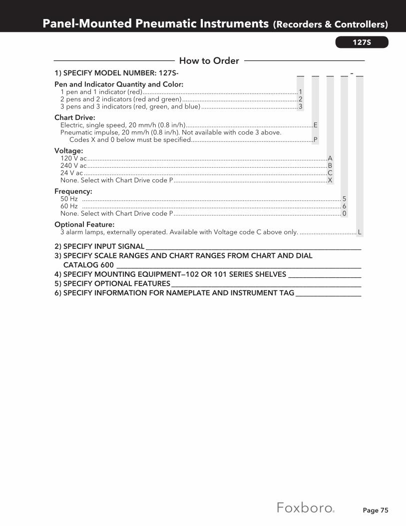
Page 75
1) SPECIFY MODEL NUMBER: 127S- __ __ __ __ – __
Pen and Indicator Quantity and Color: 1 pen and 1 indicator (red) ..........................................................................................1 2 pens and 2 indicators (red and green) ...................................................................2 3 pens and 3 indicators (red, green, and blue) ........................................................3
Chart Drive: Electric, single speed, 20 mm/h (0.8 in/h) ..........................................................................E Pneumatic impulse, 20 mm/h (0.8 in/h). Not available with code 3 above. Codes X and 0 below must be specified.......................................................................P
Voltage: 120 V ac ...........................................................................................................................................A 240 V ac ...........................................................................................................................................B 24 V ac .............................................................................................................................................C None. Select with Chart Drive code P .........................................................................................X
Frequency: 50 Hz ...................................................................................................................................................... 5 60 Hz ...................................................................................................................................................... 6 None. Select with Chart Drive code P ................................................................................................. 0
Optional Feature: 3 alarm lamps, externally operated. Available with Voltage code C above only. ................................. L
2) SPECIFY INPUT SIGNAL ___________________________________________________________3) SPECIFY SCALE RANGES AND CHART RANGES FROM CHART AND DIAL
CATALOG 600 ___________________________________________________________________4) SPECIFY MOUNTING EQUIPMENT—102 OR 101 SERIES SHELVES ____________________5) SPECIFY OPTIONAL FEATURES ____________________________________________________6) SPECIFY INFORMATION FOR NAMEPLATE AND INSTRUMENT TAG __________________
Panel-Mounted Pneumatic Instruments (Recorders & Controllers)
How to Order
127S

Page 76
nSelective Pneumatic Switching
nRemote Control Setting
nManual Loading of Final Operators
For complete specifications, refer to General Specification Sheet GS 2B-4H2 A.
135
135 Series Stations are complementary auxiliary units for 100 Series Control Systems.
Model 135S:Passes a standard input signal to a final operator or manually generates an accurate standard signal. It is normally used in control loops where a single master controller regulates two or more final oper-ators. The station contains a vertical scale, indicat-ing the input signal and the output of the manual generator. By matching the two indicators on the vertical scale and flipping the simple 2-position transfer switch, a bumpless transfer is ensured.
Model 135SG:Performs the same function as the Model 135S (above). An additional pointer is provided to display a standard input signal.
Model 135B:Performs the same functions as the Model 135S with the added feature that up to ±100% bias may be manually added to the standard input signal. It is normally used where a single master controller regulates two or more final operators, or where it remotely sets two or more controllers, and where it is necessary to bias one with respect to the other. This unit has three pointers. One is used to indicate the manually generated signal and the other two indicate the input signal before and after it is biased.
Ambient Temperature Limits:-20 and +65°C (0 and 150°F).
Input/Output Signal and Supply Pressure:
Model 135T:Provides an accurate manually adjusted standard output signal used for remote manual control of final operators or for the remote setting of any pneumatic receiver. A manual adjusting knob regulates a stable standard output indicated on a 100 mm (4 in) vertical scale.
Model 135TG:Performs the same function as the Model 135T (above). An additional pointer is provided to display a standard input signal.
Model 135TG2:Performs the same function as the Model 135T. Two additional pointers are provided to display standard input signals.
Panel-Mounted Pneumatic Instruments (Loading, Switching & Bias)
Input/Output Signal Supply Pressure
20 to 100 kPa 140 to 150 kPa 3 to 15 psi 20 to 22 psi
Functional Specifications
135 Series Manual Loading, Switching, and Bias Stations

Page 77
135
Manual Output Pointer:Output Indicator: 0.5% of calibrated span.
Repeatability of Setting: 0.25% of calibrated span.
Receiver-lndicator:Accuracy: ±0.5% of calibrated span.
Repeatability: 0.25% of calibrated span.
Dead Band: Less than 0.1% of calibrated span.
Connections:Electrical and pneumatic multiprong receptacles on rear of chassis.
Nameplate:White translucent plastic with 2.5 mm (0.1 in) high black letters. Maximum of 2 lines, 17 letters or spaces per line.
Mounting:Flush in panels 3 to 25 mm (0.13 to 1 in) thick using 102 or 101 Series Shelves. Units require 1 unit of mounting capacity.
Element:Brass bellows.
Scale:100 mm (4 in) vertical, black markings on white background.
Pointers:Manual output: black.
Bias output: red.
Inputs: green and blue.
Alarm Actuators and Alarm Lamps:Refer to Page 72.
Panel-Mounted Pneumatic Instruments (Loading, Switching & Bias)
How to Order
Performance Specifications
Physical Specifications
Optional Features
1) SPECIFY MODEL NUMBER: ________ Manual Loading ....................................................................................................................................... 135T Manual Loading with Variable Indicator .............................................................................................135TG Manual Loading with Two Variable Indicators ..................................................................................135TG2 Automatic/Manual Switching ................................................................................................................. 135S Automatic/Manual Switching with Variable Indicator .......................................................................135SG Automatic/Manual Switching and Bias ................................................................................................. 135B
2) SPECIFY INPUT AND OUTPUT SIGNALS ____________________________________________3) SPECIFY SCALE RANGES—REFER TO CHART AND DIAL CATALOG 600 _______________4) SPECIFY MOUNTING EQUIPMENT—102 OR 101 SERIES SHELVES ____________________5) SPECIFY OPTIONAL FEATURES ____________________________________________________6) SPECIFY INFORMATION FOR NAMEPLATE AND INSTRUMENT TAG __________________

Page 78
Panel-Mounted Pneumatic Instruments (Subpanel)
PM960
nPneumatic circuitry cast into base platenMany versions available, including
Manual Loader with process variable indicator
nSet point control knob secures to prevent accidental alteration
Pneumatic Subpanels are used in conjunction with pneumatic Standard Controllers for generating set point, manual output, and for auto-manual transfer switching.
PM960 Pneumatic Subpanel
Pneumatic SubpanelFront finish ....................... bezel grey RAL 7037 facia grey RAL 7035Supply air ......................... 1.4± 0.1 bar / 20 ± 1.4 psiManual-Auto-switch ....... flat slide valve
Pressure Indicator (built in)Version ............................. single-or double indicatorSystem.. ............................ bourdon tubeIndication range ............. 0 to 1.2 bar / 0 to 18 psiScale length .................... 44mmError limit ......................... ≤ 1 % f. s. d.Cross-matching error .... ≤ 0.5 % f. s. d.(Double indicator)
Pneumatic Signal Generator (built in)Output adjustable ............0 to supply air pressureAir consumption ...............≤ 100 l/h per signal gen.Supply air dependency ...≤ 0.2 %/0.1 barTemperature effect ..........≤ 0.3 %/10 K
MaterialsBourdon tube ....................bronzeOther components ..........al, brass, zinc-plated steel
For complete specification, refer to Product Specification Sheet PSS EIC4315 A-(en)
Version Front View Circuit Diagram Pneum. ConnectionsManual Loader
-A1 Zul. Supply air5yH Manual output
For Local Set Control
-F
1 Zul. Supply air2S Switch signal3w Setpoint4yA Controller output5Y Output

Page 79
___ ___ ___Pneumatic Subpanel PM960Version: Manual Loader ............................................................................................................................... -A Manual Loader with process indicator ....................................................................................... -B Double Manual Loader. ............................................................................................................... -C for slave control ............................................................................................................................. -D for Slave control, controller with PI switch. ................................................................................ -E for local set control ....................................................................................................................... -FIndicating Range (Scale): 0-1.2bar ................................................................................................................................................... 1 0-18psi ..................................................................................................................................................... 2 0-120kPa .................................................................................................................................................. 3Options: Wall mounting plate .....................................................................................................................................-W Tag No. Labeling with inscription ................................................................................................................-L
PM960 , 556, 557
Units provide output proportional to mathematical function of input. Model 557 performs square root function only.
Input and Output Signals:20 to 100 kPa or 3 to 15 psi, as specified.
Supply Pressure Limits:130 and 150 kPa or 19 and 22 psi.
Ambient Temperature Limits: -40 and +80°C (-40 and + 180°F).
Air Consumption Under Normal Operation:<.10 m3/h (.06 scfm) at standard conditions.
Air Connections:All air connections are tapped for 1/4 NPT.
Mounting:A bracket is supplied for vertical mounting on a rack or DN 50 or 2 in pipe. The bracket is designed for either horizontal or vertical pipes or rack struts.
Functions and Related Equations:The 556 Series performs any one of four functions and solves an equation as shown in the table. The 557 performs square root only.
A, B. and C are pneumatic signals expressed as decimal equivalents of percent of span. f = Scaling factor (limits: 0.750 and 3.500). s = Span factor for C signal (limits: 0.050 and
1.000). z = Zero suppression of C signal (limits: 0.000
and 0.950). NOTE: The sum of s and z must equal 1.000.
nVersatile • Multiply • Divide • Square • Square rootnWide Range of Applications • Flexible scaling for multiplication and
divisionnBuilt-in Function Switch • To select any of four computing
functionsnWeatherproof • Plastic cover • Die-cast, low copper content aluminum
alloy manifold • IEC IP53 and NEMA Type 3For complete specifications, refer to Product Specification Sheets PSS 2B-5E1 A and B.
Panel-Mounted Pneumatic Instruments (Computing Elements)
Function Equation
Multiplication A = fB(z+sC) Division B =
(f) (z A+ sC)
Square Root B = √A
Square A = C2
Functional Specifications
556 Series and Model 557 Pneumatic Analog Computers
How to Order

Page 80
556, 557
Panel-Mounted Pneumatic Instruments (Computing Elements)
1) SPECIFY MODEL NUMBER: ________
............................................................................556-8 ............................................................................556-9 .......................................................................... 556-10 .......................................................................... 556-11 ............................................................................. 557
(a) Refer also to Model 557, and accuracy statement in “PERFORMANCE SPECIFICATIONS.”
2) SPECIFY INPUT/OUTPUT RANGE IN PROCESS UNITS ________________________________3) SPECIFY FOR MODELS 556-8 AND 556-9:
SUPPLY THE VALUE OF f, s, AND z _________________________________________________ DEFINE INPUT/OUTPUT SIGNAL RANGE DESIRED, kPa OR psi _______________________
4) SPECIFY INFORMATION FOR INSTRUMENT TAG ___________________________________
Repeatability:0.1 % of output span.
Accuracy:Multiplication: ±0.5% of output span referred to input.
Division: ±0.5% of output span referred to input.
Square Root:556: ±0.25% of output span referred to input. 557: ±0.5% of output span referred to input.
Square: ±0.5% of output span.
Environmental Protection:The housing construction is weatherproof. It is dust-protected as defined in IEC IP53 and provides the environmental protection of NEMA Type 3.
Materials of Construction:Cover: Molded plastic with textured gray finish.
Manifold: Low copper content aluminum alloy die-casting with a gray epoxy finish.
Flexures: 17-4 PH stainless steel.
A and C Bellows: Brass.
B Diaphragm: Copper alloy.
Function Formula
Multiplication A = fB(z+sC)
Division B = A/f(z + sC)
Square Root (a) B = √A
Square a + C2
Square Root B = √A
Performance Specifications
Physical Specifications
How to Order
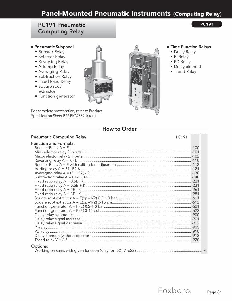
Page 81
____ ___Pneumatic Computing Relay PC191
Function and Formula: Booster Relay A = E ........................................................................................................................... -100 Min.-selector relay 2 inputs ............................................................................................................... -101 Max.-selector relay 2 inputs .............................................................................................................. -102 Reversing relay A = K - E ................................................................................................................... -110 Booster Relay A = E with calibration adjustment ........................................................................... -113 Adding relay A = E1+E2-K ................................................................................................................ -121 Averaging relay A = (E1+E2) / 2 ...................................................................................................... -130 Subtraction relay A = E1-E2 +K ........................................................................................................ -140 Fixed ratio relay A = 0.5E - K ............................................................................................................ -221 Fixed ratio relay A = 0.5E + K ........................................................................................................... -231 Fixed ratio relay A = 2E - K ............................................................................................................... -261 Fixed ratio relay A = 3E - K ............................................................................................................... -281 Square root extractor A = E(xp=1/2) 0.2-1.0 bar ........................................................................... -611 Square root extractor A = E(xp=1/2) 3-15 psi ................................................................................ -612 Function generator A = F (E) 0.2-1.0 bar ........................................................................................ -621 Function generator A = F (E) 3-15 psi ............................................................................................. -622 Delay relay symmetrical .................................................................................................................... -900 Delay relay signal increase ............................................................................................................... -901 Delay relay signal decrease .............................................................................................................. -902 PI-relay ................................................................................................................................................. -905 PD-relay ............................................................................................................................................... -910 Delay element (without booster) ..................................................................................................... -913 Trend relay V = 2.5 ............................................................................................................................ -920
Options: Working on cams with given function (only for -621 / -622) ................................................................... -A
Panel-Mounted Pneumatic Instruments (Computing Relay)
PC191
nTime Function Relays• Delay Relay• PI Relay• PD Relay• Delay element• Trend Relay
nPneumatic Subpanel• Booster Relay• Selector Relay• Reversing Relay• Adding Relay• Averaging Relay• Subtraction Relay• Fixed Ratio Relay• Square root
extractor• Function generator
For complete specification, refer to Product Specification Sheet PSS EIO4332 A-(en)
How to Order
PC191 Pneumatic Computing Relay

Page 82
____ ___Pneumatic Signal Selection Relay PS953
Function: Signal selector relay, mechanical setpoint change-over if setpoint is exceeded ..................... -100 Signal selector relay, mechanical setpoint change-over if setpoint is drops ............................ -101 Three-way signal selector relay, mech. setpoint, change-over if setpoint is exceeded, reversing if setpoint is drops ....................................................................................................... -111 Three-way signal selector relay, mech.setpoint (0,2-1,0 bar) with self-latch, change-over if setpoint is exceeded reversing manual (a) ..................................................... -112 Three-way signal selector relay, mech.setpoint (0-1,0 bar) with self-latch, change-over if setpoint is exceeded, reversing manual (a) .................................................... -114 Lock-in relay single-action ................................................................................................................ -200 Lock-in relay double-action. ............................................................................................................. -210 Limiting relay for max.pressure. ....................................................................................................... -410 Change-over relay pneum. conn. 1/8 - 27 NPT ............................................................................. -611 Change-over relay pneum. conn. 1/4 - 18 NPT ............................................................................. -613
Options: Push-button valve for venting pneum. signal lines (only for -112/114) ................................................. -A Adapter Plate for PS953-210 for large pneumatic connector .................................................................M Adapter Plate for PS953-200 for NAMUR mounting instead of SOV .....................................................N
NOTES:(a) With Option - A(b) With Option - B
PS953
nSignal selector relays • Signal selector Relay with mechanical
or pneumatic setpoint adjustment for pressure and pressure difference
nRelays for control applications • Lock-in relay • Limiting relay • Changeover relay • Push-button valve
For complete specification, refer to Product Specification Sheets PSS EIO4331 A-(en) for PS953
Panel-Mounted Pneumatic Instruments (Computing Relay)
PS953 Pneumatic Signal Selection Relay
How to Order

Page 83
130MD, 130PD, 130FD, 138, 130M-N, 102, 101, 120
Panel-Mounted Pneumatic Instruments (Miscellaneous)
138 Series Remote Mounted Pneumatic Controllers
130MD, 130PD &130FD Series Pneumatic CONSOTROL Control Stations
138 Series Remote Mounted Pneumatic Controllers are used with 130MD,130PD, and 130FD Series Control Stations. They provide the response advantage of a local controller with the convenience of a Panel-Mounted display.
130MD, 130PD, and 130FD Series Pneumatic CONSOTROL Control Stations provide Panel-Mounted measurement, set point, and auto/ manual transfer functions to operate separately mounted controllers. The stations are used with the 138 Series Controllers to minimize time lag resulting from long distances between control panels and the process.
102 & 101 Series Pneumatic CONSOTROL Shelves
130M-N Series Pneumatic CONSOTROL Indicating Gap Controllers
102 and 101 Series Pneumatic CONSOTROL Shelves allow flush panel mounting of pneumatic CONSOTROL instruments in panels. They are compact units, available in ten sizes for one to ten instruments. The shelves allow instruments to be wholly or partially withdrawn without interfering with the operation of others.
The Model 130M-N7 Differential Gap Controller is an on/off unit with an adjustable inert zone (gap) within which the controller will not respond to changes in the mea-surement.
The Model 130M-N94 Gap Action Floating Controller provides stan-dard proportional plus integral con-trol action when the measurement exceeds the high or low gap limit.
Alarm Actuatorsand Alarm Lamps
120 Series Pneumatic CONSOTROL Recorders
100 Series Pneumatic Alarm Actuators are available integrally mounted in CONSOTROL 100 instruments. The actuators are operated directly by the pneumatic input signals. They provide high sensitivity, accuracy, and dependability by eliminating intermediate receiver mechanisms. A wide variety of alarm configurations is available.
120 Series Pneumatic CONSOTROL Recorders record up to four process measurements received as standard pneumatic transmission signals from remote transmitters. Large, brightly colored pens clearly indicate the measurement. The recording is on a SCAN-FOLD chart.

Page 84
Converters
Converters
Many processes require both electronic and pneumatic instrumentation. Converters allow you to integrate that combination into your control strategy.
Foxboro makes converters for both purposes:
CURRENT-TO-PNEUMATIC (I/P) E69 SERIES • Available with a selection of input/output signals• Small, compact, lightweight—for easy installation• High air delivery rate for direct valve actuation
CURRENT-TO-PNEUMATIC (I/P) IP24 SERIES • Available with a large selection of input/output signals• Designed for field service / heavy duty application• Stainless steel version as option

Page 85
Converters (Current-to-Pneumatic)
E69F and E69R Series Current-to-Pneumatic Converters
E69, E69R
nLight, Compact • Easy to installnLow Air Consumption • Reduced operation costsnHigh Air Capacity • Eliminates need for volume boostersnChoice of Various Input and Output Signals • Suitable for all applicationsnSealed Air Purged Case (E69F) • Long-term dependability in dirty
environmentsnPrecise Performance
For complete specifications, refer to Product Specification Sheets PSS 4-8B1 A (E69F) and 2B-2A2 A (E69R).
E69F and E69R Series Current-to-Pneumatic Converters accept a dc milliampere input signal and convert to a proportional pneumatic output signal.
Supply Pressure: (a)
a) Not less than 20 kPa or 3 psi above maximum output.
Electrical Classification:FM, CSA, and ATEX certified. Explosion proof and intrinsically safe versions available. Refer to Foxboro for complete specifications.
requirements of IEC IP65 and provides the environmental protection of NEMA Type 4.
Mounting:Valve yoke, surface, or DN 50 or 2 in pipe. Calibrated for vertical mounting unless otherwise specified. Bracket is supplied as standard.
Input/Output Connections:Electrical: Tapped 1/2 in for conduit fitting to connect to a pair of 0.5m (18 in) long 18 AWG (1.0 mm2) twisted leads.
Pneumatic:1/4 NPT for air supply and output signal.
Input Signal Ranges (mA dc):4 to 20, 4 to 12, 12 to 20.10 to 50, 10 to 30, 30 to 50.
Output Signal Ranges:20 to 100 kPa or 3 to 15 psi.40 to 200 kPa or 6 to 30 psi.3 to 27 psi.7 to 125 kPa or 1 to 18 psi.7 to 220 kPa or 1 to 32 psi.
Input Impedance:170 Ω (4 to 20 mA dc).27 Ω (10 to 50 mA dc).
Accuracy: Output Signal codes 2 and 3: ±1.0% of calibrated span.
Output Signal codes 7 and 8: ±2% of calibrated span.
Linearity:0.5% of calibrated span typical.
Repeatability:0.25% of calibrated span typical.
E69F Enclosure:Die-cast copper (1% maximum) aluminum alloy body and cover (ASTM 512A and 512B), with a vinyl or epoxy powder finish. Meets the
Nominal Limits
140 kPa or 20 psi 130 and 160 kPa or 19 and 23 psi 240 kPa or 35 psi 225 and 260 kPa or 33 and 38 psi
Functional Specifications
Physical Specifications
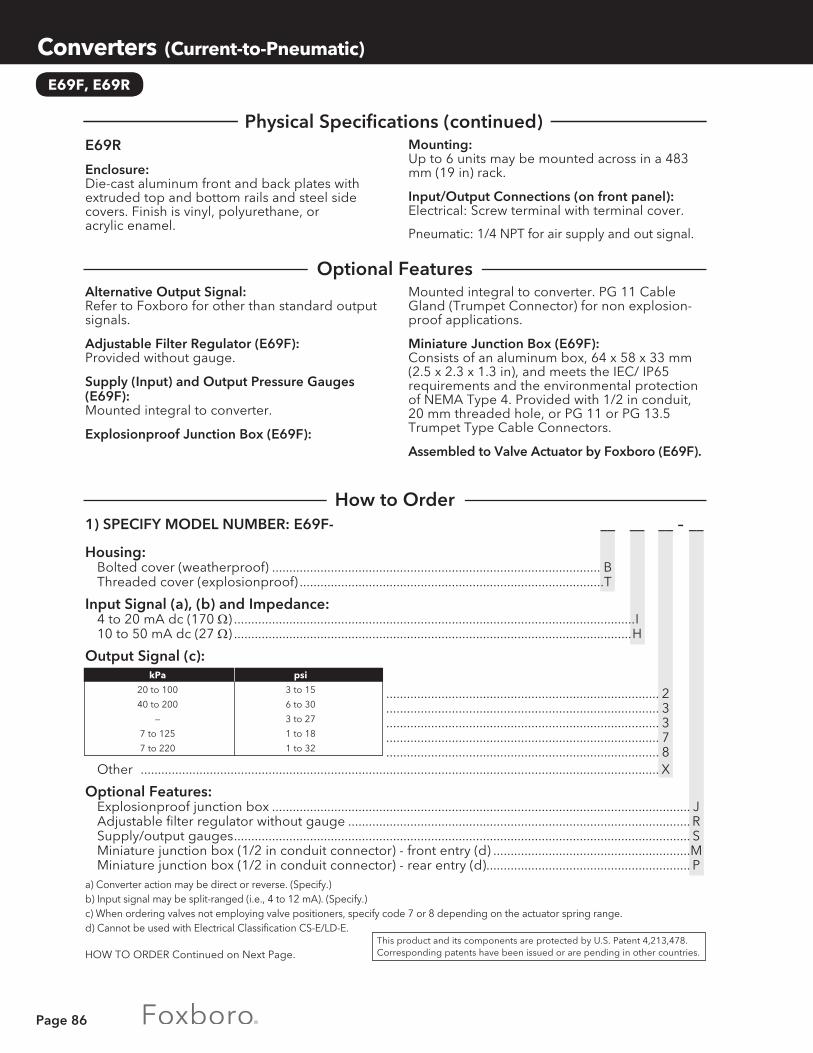
Page 86
E69F, E69R
Converters (Current-to-Pneumatic)
1) SPECIFY MODEL NUMBER: E69F- __ __ __ – __
Housing: Bolted cover (weatherproof) ............................................................................................... B Threaded cover (explosionproof) ........................................................................................T
Input Signal (a), (b) and Impedance: 4 to 20 mA dc (170 Ω) ....................................................................................................................I 10 to 50 mA dc (27 Ω) ...................................................................................................................H
Output Signal (c):
............................................................................... 2 ............................................................................... 3 ............................................................................... 3 ............................................................................... 7 ............................................................................... 8
Other ...................................................................................................................................................... X
Optional Features: Explosionproof junction box ......................................................................................................................... J Adjustable filter regulator without gauge ................................................................................................... R Supply/output gauges .................................................................................................................................... S Miniature junction box (1/2 in conduit connector) - front entry (d) .........................................................M Miniature junction box (1/2 in conduit connector) - rear entry (d). .......................................................... Pa) Converter action may be direct or reverse. (Specify.)b) Input signal may be split-ranged (i.e., 4 to 12 mA). (Specify.)c) When ordering valves not employing valve positioners, specify code 7 or 8 depending on the actuator spring range.d) Cannot be used with Electrical Classification CS-E/LD-E.
HOW TO ORDER Continued on Next Page.
Mounted integral to converter. PG 11 Cable Gland (Trumpet Connector) for non explosion-proof applications.
Miniature Junction Box (E69F): Consists of an aluminum box, 64 x 58 x 33 mm (2.5 x 2.3 x 1.3 in), and meets the IEC/ IP65 requirements and the environmental protection of NEMA Type 4. Provided with 1/2 in conduit, 20 mm threaded hole, or PG 11 or PG 13.5 Trumpet Type Cable Connectors.
Assembled to Valve Actuator by Foxboro (E69F).
Alternative Output Signal:Refer to Foxboro for other than standard output signals.
Adjustable Filter Regulator (E69F): Provided without gauge.
Supply (Input) and Output Pressure Gauges (E69F):Mounted integral to converter.
Explosionproof Junction Box (E69F):
Mounting:Up to 6 units may be mounted across in a 483 mm (19 in) rack.
Input/Output Connections (on front panel): Electrical: Screw terminal with terminal cover.
Pneumatic: 1/4 NPT for air supply and out signal.
E69R
Enclosure:Die-cast aluminum front and back plates with extruded top and bottom rails and steel side covers. Finish is vinyl, polyurethane, or acrylic enamel.
kPa psi
20 to 100 3 to 15
40 to 200 6 to 30
— 3 to 27
7 to 125 1 to 18
7 to 220 1 to 32
This product and its components are protected by U.S. Patent 4,213,478. Corresponding patents have been issued or are pending in other countries.
Optional Features
Physical Specifications (continued)
How to Order

Page 87
Converters (Current-to-Pneumatic)
E69, E69R
1) SPECIFY MODEL NUMBER: E69R- __ – __
Housing:Input Signal (a), (b) and Impedance: 4 to 20 mA dc (170 Ω) ............................................................................................................................ I 10 to 50 mA dc (27 Ω) ........................................................................................................................... H
Output Signal (c):
........................................................................................ 2 ........................................................................................ 3 ........................................................................................ 3 ........................................................................................ 7 ........................................................................................ 8
Other ............................................................................................................................................................... Xa) Converter action may be direct or reverse. (Specify.)b) Input signal may be split-ranged (i.e., 4 to 12 mA) (Specify.)c) When ordering valves not employing valve positioners, specify code 7 or 8 depending on the actuator spring range.
2) SPECIFY DIRECT OR REVERSE ACTION______________________________________________3) SPECIFY OUTPUT SIGNAL __________________________________________________________4) SPECIFY ELECTRICAL CLASSIFICATION _____________________________________________5) SPECIFY OPTIONAL FEATURES _____________________________________________________6) SPECIFY INFORMATION FOR INSTRUMENT TAG ____________________________________
kPa psi
20 to 100 3 to 15
40 to 200 6 to 30
— 3 to 27
7 to 125 1 to 18
7 to 220 1 to 32
How to Order (continued)

Page 88
IP24
For conversion of a standard electrical signal into a standard pneumatic signal.
For complete specification, refer to Product Specification Sheet PSS EVE0401 A-(en).
nHigh air capacitynLow input resistancenEasy adaptation of the Converter to
ranges 0 to 20 mA or 4 to 20 mAnMode of action normal or reversenProtection Class IP54 or IP65nVersion in II 2 G EEx ia IIC T6 acc. to ATEXnStainless Steel 316 as option
Converters (Current-to-Pneumatic)
IP24 Current to Pneumatic Converter for Field & Service
How to Order
InputSignal range ............................... 4 to 20 mA/0 to 20 mA/ 0 to 10 mA/0 to 10 VInput resistance (at 20 °C) Normal Version & Vers. II 2 G EEx ia IIC T6 acc. to ATEX ................................... <220 OhmsSignal Range 0 to 10 mA / 0 to 10 V .......... <1000 Ohms
OutputSignal range normal ................. 0.2 to 1 bar, 3 to 15 psi, 20 to 100 kPa, 0.2 to 4 barSignal range normal ................. 1 to 0.2 bar, 15 to 3 psi, 100 to 20 kPa, 4 to 0.2 bar
Supply air .................................... 1.4 ±0.1 bar ( 20 ±1.4 psi)Air consumption ........................ <100 l/hSupply air .................................... free of oil, dust, water according to ISO 8573-1 Max. particle-size and -density ... Class 2 Max. oil contents ................... Class 3
Transmission performanceNon-linearity (terminal-based) .. <0.3% of final valueHysteresis .................................... <0.1%Supply pressure dependence ... <0.25 %/0,1 barTemperature influence Output normal ....................... <0.3%/10 K Output reverse ...................... <0.5%/10 KSensitivety level ......................... <0.02%
Housing Material .................................... Aluminum casting, finished Protection Class ...................... IP54 or IP65
___ ___ ___Pneumatic Signal Selection Relay IP24
Input: Signal Range 0 - 20 mA ................................................................................................................. -A Signal Range 4 - 20 mA ................................................................................................................. -B Signal Range 0 - 10 mA(a) ............................................................................................................ -C Signal Range 0 - 10 V(a) ................................................................................................................ -D
Input: Signal Range 0. -1 bar. ............................................................................................................................K Signal Range 3-15 psi ..............................................................................................................................L Signal Range 20-100 kPa ....................................................................................................................... M Signal Range 0.2-4 bar(a). ...................................................................................................................... N Signal Range 0.2-5 bar(a) ........................................................................................................................P Signal Range 0.2-6 bar(a) ....................................................................................................................... Q
Mode of Action: Normal (For Version ZZZ) ............................................................................................................................... D Normal (For Version EAA according to ATEX) .............................................................................................E Reverse ..............................................................................................................................................................R
HOW TO ORDER Continued on Next Page.
Page 89
____ ___Electrical Certification: II 2 G EEx ia IIC T6 ................................................................................................................................ EAA Without ...................................................................................................................................................ZZZ
Options: Attachment Kit For Pipe Mounting ............................................................................................................... -A Protection Class IP65 ...................................................................................................................................... -B Calibration In kp/cm .......................................................................................................................................-C Assembled free of oil and Grease / Designed for Aux. Energy Oxygen. ............................................... -S
Tag No. Labeling: Stamped With Weather Resistant Color ......................................................................................................-G Stainless Steel Label Fixed With Wire .......................................................................................................... -L
NOTES:(a) Only available with Mode of Action Code D
Special VersionNr EP Specifications
EP0194 Special setting: Input 4-20 mA ≥ Output 0.2-0.6 bar
EP0210 Special setting: Input 4-20 mA ≥ Output 0.2-4 bar
EP0300 IP24 in Stainless Steel Housing 316
EP0305 Special setting: Input 4-20 mA ≥ Output 0.4-2 bar
EP0314 With 2 additional gauges (air supply, output)
How to Order (continued)
Converters (Current-to-Pneumatic)
IP24

Page 90
E69P Series Current-To-Pneumatic Valve Positioners
2A Series Cylinder Actuator with Power Positioner
The E69P Series Current-to-Pneumatic valve Positioner converts a direct current milliampere input signal into a pneumatic output signal for positioning control valve actuators. It eliminates the need for a separate converter and a separate positioner. It is available with the following input signal ranges (mA): 4 to 20, 4 to 12, 12 to 20, 10 to 50, 10 to 30, 30 to 50 with a corresponding output sugnal of up to 240 or 420 dPa (35 or 60 psi, 2.4 or 4.2 bar of kg/cm2).
The 2A Series Cylinders are used to actuate dampers, gates, shutters, doors, and large control valves. Power positioners are required with all pneumatic cylinders for throttling action. They convert the standard 20 to 100 kPa (3 to 15 psi) controller signal to full supply pressure on the cylinder piston and assure precise, positive positioning. Cylinders are available in bore sizes 83 through 355 mm (3 1/4 through 14 in) with strokes up to 810 mm (32 in).
P Series Pneumatic Spring Diaphragm Actuators
Models 20F/P50 & 30C/P110 Diaphragm Lever Actuators
The P Series Actuators can operate a variety of control valves, dampers, louvers, and gates. They are lightweight field-reversible units with low hysteresis and fast, precise response.
Nominal input signal: 20 to 100 or 40 to 200 kPa (3to 15 or 6 to 30 psi).
The Models 20F/P50 and 30C/P110 Diaphragm Lever Actuators are used to actuate dampers, gates, and butterfly valves. The topworks of the size P50 and P110 Diaphragm Actuators are made of vinyl coated, die-cast aluminum. Maximum input pressure is 420 kPa (60 psi). Bracket material is cast iron, and the carbon steel lever is predrilled. Lever strokes range from 116 to 254 mm (4.56 to 10 in).
Maximum Stroke Effective Area Material Model mm in m2 in2 Construction P25 19 3/4 0.016 25 aluminum P50 38 1 1/2 0.032 50 with cast P110 57 2 1/4 0.071 110 iron yoke
2A, P SERIES, 20F/P50, 30C/P110
Control Valves (Actuators)

Page 91
SRI986 Electro-Pneumatic Positioner
SRP981 Pneumatic Positioner
The SRI986 Positioner is designed to control pneumatic valve actuators from control systems and electrical controllers with electric control signals. It offers an easy adjustment by two mechanical screws.• Split range up to 3-fold possible• Input Signal from 0 to 20 mA or 4 to 20 mA• Explosion protection: o II 2 G EEx i (intrinsic safety) according to ATEX o Intrinsic safety according to FM and CSA• Ambient temperature –40 to 80°C (–40 to 176°F)
The SRP981 Positioner is designed to control pneumatic valve actuators with pneumatic control signals. It offers an easy adjustment by two mechanical screws.• Split range up to 4-fold possible• Input Signal from 0.2 … 1 bar (3 … 15 psig)• Supply pressure up to 6 bar (90 psig)• Single or double acting• ATEX Explosion protection II2 G EEx c (constructive safety)• Stainless steel 316 housing as option
SMP981 Pneumatic Position Transmitter
SRI983 Electro-Pneumatic Positioner
For the conversion of linear or rotary movements actuators into a 0.2 to 1 bar pneumatic signal.• Universal matching to all strokes by means of
differing range springs.• Simple installation and adjustment. Zero and
range settings non-interactive• ATEX Explosion protection II2 G EEx c
(constructive safety)
The SRI983 Positioner is designed to control pneumatic valve actuators from control systems and electrical controllers with electric control signals. It offers an easy adjustment by two mechanical screws.- Explosion protection:• II 2 G EEx d (flameproof) according to ATEX
explosion proof according to FM and CSA• Ambient temperature –40 to 80°C (–40 to
176°F)
For more information, please refer to our main instrument catalog, Foxboro Measurements and Instruments Catalog (PN FX-0181).
SRP981, SRI986, SRI983, SMP981
Control Valves (Positioners)
Page 92
Accessories and Supplies
Humitex Circular and Strip Charts
Standard circular charts are printed with gray ink, 1 side only, on 0.122 mm (0.0048 in) thick paper. Circular charts with heavy paper are printed on 0.178 mm (0.0070 in) paper. Charts are packaged 100 to a box.
Instrument Chart Size125 mm (5 in) Side-MountedRecorder …………………………125 mm (5 in) (a)12 Series Recorders ………………300 mm (12 in)40/740 Series Recorders ………..300 mm (12 in)39A Series Flow Recorders …..300 mm (12 in) (a)39 B Series Flow Recorders …………...MW Series 300mm (12in)(a)740R Series Recorders …………...300 mm (12 in)
a) Always printed on heavy paper.
Foxboro also prints circular charts for American Meter, Arcco-Anubis, Bailey, Bristol, Gotham (Ametek), Honeywell (Brown), Mercury, Palmer, Ranarex (Permutit), Rockwell, Taylor, UGC Industries, Warren Controls (Tagliabue), and Weksler which are made to their specifications.
Any Foxboro instrument user with an estimated yearly requirement of 500 boxes of circular and/or 500 boxes of strip charts or more may request a Chart Purchase Agreement. Under the agreement system, quantity prices are applied to the individual chart purchase order. The agreement is continuous, reviewed yearly for actual purchases, and a 30-day advance notice to changes is given. Refer to Foxboro with your annual requirements to receive a Chart Purchase Agreement.
Minimum Order Quantity—15 boxes of circular charts or 15 boxes of strip charts.
Toll Free Number
To order charts, call 888-FOXBORO (888-369-2676).
Types of Calibration Charts Available for Circular and Strip Charts
Uniform, Differential Pressure, Flow (Type 27), Vacuum Pressure, Square Root, Vapor Pressure, Dairy Charts, Dew Point, Thermocouple, Thermopile, Flow-Open Channel Weir and Flume, Log Function, Specific Gravity, and Balsbaugh.
Foxboro recording charts complement the precision and fine craftsmanship of our wide range of recording instruments. Charts combine the essential elements of special high-quality paper with rigidly controlled printing and trimming procedures. Over 17,000 different charts can be supplied in ranges and calibrations to meet the requirements of practically any process recording application. Special charts and new ranges not listed in the Chart Catalog and Dial List (Catalog 600) may require a new electro printing plate for specific customer needs. Contact our nearest Branch Office for Catalog 600.
Options for 300 mm (12 in) Circular Charts:
b) Add as suffix to circular chart number.c) Add Foxboro backprint number.d) Specify drop time and/or day of the week.e) Specify time.f) Must be available as an existing chart; see Catalog 600.
Description Code (b)
Heavy Paper -HP Backprinting (c) -BP Mullins Slotting (d) -MS-HP Overprinting of Two-Color Charts (f) -OP Color of Ink on Chart: Green -GRN Scanner Blue Ink -BLU-SBI Black -BLK Aqua -AQUA Dark Blue -DBLU Shrink Wrap -SW
Chart Purchase Agreement
Circular Chart Specifications
Humitex Circular and Strip Charts

Page 93
Accessories and Supplies
Recorders Chart
E20S 4 in Roll or SCAN-FOLD 53 For 4 in Roll, specify chart number 54 suffix -T if time numbering is required. 64 120 For SCAN-FOLD, specify chart number 220S suffix -6TX if time numbering is required. E27R 126S 100 mm Roll only 127S 226S Specify chart number suffix -T if time numbering is required. 227S 760R 761R L0120NP
762R
Fold - L0122RQ 50 Divisions - L0122RS 0-100 Linear Roll - L0122RR 50 Divisions - L0122RT 0-100 Linear
751R
Fold - L0122RS 0-100 Linear Roll - L0122RT 0-100 Linear
4 in Roll,100 mm Roll, and SCAN-FOLD charts can be supplied with or without time mark numbering. Standard time mark numbering is the hour of the day printed on the left side of the chart at 2-hour intervals (on the even hour). The standard speed for the 4 in Roll and SCAN-FOLD is 3/4 in/h which coincides with the chart drive speed. The standard speed for the 100 mm Roll is 20 mm/h.
A large selection of non-standard time mark numbering is available to match the chart speeds of your recorders. Refer to Catalog 600 for a listing.
4 in Roll Chart ........................................................................................................... One 30-day chart per box100 mm Roll Chart ................................................................................................... One 30-day chart per boxSCAN-FOLD Chart .................................................................................................. Two 16-day charts per box
Strip Chart Specifications

Page 94
Accessories and Supplies
Pen Arm, Item 1 Fiber Tip Pens (Package of 6), Item 2
Pen Location
Part Identification Part A Length
Number Holes Color Number mm in
1-Pen 0044899 2 Red L0121CH 12 0.47
2-Pen outer 0046965 3 Violet L0121CR 6 0.24 inner 0044899 2 Red L0121C J 12 0.47
nLarge, Disposable, Fiber Tip Pens for Circular Chart Recording Instruments
nDesigned to Write 365 meters (1200 feet)
nPrepackaged 6 Pens per Card
12R Series Round Case Recorders:
12RD (1 to 3 Pen) and 12RM (1 and 2 Pen) Series Round Case Recorders:
To order, call 888-FOXBORO (888-369-2676).
Pen Arm, Item 1 Fiber Tip Pens (Package of 6), Item 2
Pen Location
Part Identification Part A Length
Number Holes Color Number mm in 1-Pen 0044897 2 Red L0121CH 12 0.47
2-Pen inner M0122AC 1 Violet L0121CM 6 0.24 outer 0044897 2 Red L0121CH 12 0.47
3-Pen inner M0122AC 1 Violet L0121CM 6 0.24 center 0044897 2 Red L0121CH 12 0.47 outer M0122AB 3 Green L0121CU 18 0.71
4-Pen inner M0122AC 1 Violet L0121CM 6 0.24 next to inner 0044897 2 Red L0121CH 12 0.47 next to outer M0122AB 3 Green L0121CU 18 0.71 outer M0122AA 0 Blue L0121DA 24 0.94
Pen Arm, Item 1 Fiber Tip Pens (Package of 6), Item 2
Pen Location
Part Identification Part A Length
Number Holes Color Number mm in
1-Pen 0044899 2 Red L0121CT 18 0.71
2-Pen inner 0046964 1 Violet L0121CR 12 0.47 outer 0044899 2 Red L0121CT 18 0.71
3-Pen inner M0122NE 0 Violet L0121CR 12 0.47 center 0046964 1 Red L0121CT 18 0.71 outer 0044899 2 Green L0121CZ 24 0.94
Pens and Pen Arms
Recording40, 40M, 40P, and 39 Series Rectangular Case Recorders:

Page 95
Accessories and Supplies
Pen Arm/lndex, Item 1 Fiber Tip Pens (Package of 6), Item 2
Controller
Pen A Length
Type Location Part Part
Number Identification
Color Number mm in Holes or Color
Single Action 1-Pen 0044897 2 Index 0032301 Plain Red L0121CH 12 0.47
2-Pen
Single Action inner M0122AC 1 Violet L0121CR 12 0.47
with outer 0044897 2 Red L0121CT 18 0.71
Additional Pen
Index M0122LT Red
3-Pen Single Action inner M0122AC 1 Violet L0121CR 12 0.47 with 2 center 0044897 2 Red L0121CT 18 0.71 Additional Pens outer M0122AB 3 Green L0121CZ 24 0.94 Index M0122LT Red
1-Pen 0044897 2 Index Triple Setting inner M0122LS Violet Red L0121CY 24 0.94 center M0122LT Red outer M0122MA Green
2-Pen Ratio inner M0122AC 1 Violet L0121CR 12 0.47 outer 0044897 2 Red L0121CT 18 0.71 Index M0122LS Violet
3-Pen Ratio with inner inner M0122AC 1 Violet L0121CR 12 0.47 Additional Pen center 0044897 2 Red L0121CT 18 0.71 outer M0122AB 3 Green L0121CZ 24 0.94 Index M0122LS Violet
1-Pen 0044897 2 Duplex Index Red L0121CT 18 0.71 inner M0122LT Red outer M0122LS Violet
2-Pen Auto-Selector, inner M0122AC 1 Dual, or Duplex outer 0044897 2 Red L0121CT 18 0.71 with Index Violet L0121DB 24 0.94 Additional Pen inner M0122LT Red outer M0122LS Violet
1. On multiple pen recorders, if pens L0121CR (Violet), LC 121CS (Black), L0121CP (Green), or L012 CQ (Blue) are used as arcing pens, then the red inner pen (L0121CJ) must be used. Its length is 6 mm (0.24 in)
2. Black pens may be substituted for red or violet as follows: Use L0121CN for pen arm lengths of 6 mm (0.24 in) Use L0121CS for pen arm lengths of 12 mm (0.47 in)3. If replacing box pens with fiber tip pens, the color dot on the pen arm (Item 1 in drawing on preceding page) must be removed.
Disposable Fiber Tip Pen Cartridges for 40P/40M/12 and 740 Chart Recorders: A-Length mm in Red Violet Green Blue Black
6 0.24 L0121CJ L0121CM L0121CK L0121CL L0121CN 12 0.47 L0121CH L0121CR L0121CP L0121CQ L0121CS 18 0.71 L0121CT L0121CW L0121CU L0121CV L0121CX 24 0.94 L0121CY L0121DB L0121CZ L0121DA L0121DC
40, 40M, and 40P Series Rectangular Case Recording Controllers:
Recording Controllers

Page 96
Alumel is a trademark of Hoskins Manufacturing Company. Aminco is a trademark of American Instrument Company. Bakelite is a trademark of Union Carbide Corporation. Carpenter is a trademark of Carpenter Technology Corporation. Chromel is a trademark of Hoskins Manufacturing Company. Dacron is a trademark of E. I. duPont de Nemours & Company, Inc. Duranickel is a trademark of Huntington Alloys, Incorporated. Fluorinert is a trademark of 3M Company. Fluorolube is a trademark of Hooker Chemical Corporation. Grafoil is a trademark of Union Carbide Corporation. Hastelloy is a trademark of Stellite Division of Cabot Corporation. HART ia a trademark of the HART FoundationInconel is a trademark of Huntington Alloys, Incorporated. Kel-F is a trademark of 3M Company. Kynar is a trademark of The Pennwalt Corporation. Linatex is a trademark of Wilkinson Process Rubber, Ltd. Monel is a trademark of Huntington Alloys, Incorporated. Ni-Span is a trademark of Huntington Alloys, Incorporated. Noryl is a trademark of The General Electric Company. Ryton is a trademark of Phillips Petroleum Company. Teflon is a trademark of E. I. duPont de Nemours & Company, Inc. Tefzel is a trademark of E. I. duPont de Nemours & Company, Inc. TriClamp is a trademark of Ladish Company. Viton is a trademark of DuPont Dow Elastomers L.L.C. 17-4 PH is a trademark of Armco Steel Corporation. 17-7 PH is a trademark of Armco Steel Corporation.
The following are trademarks of The Foxboro Company:
CONSOTROL DEWCEL d/p Cell DYNATHERMFOXBOROHUMITEXSCANFOLD
The lntelligent Automation People is a Service Mark of The Foxboro Company.
Trademarks
Page 97
101 Series Shelf ................................Page 83120 Series Recorders ................................ 83130 M-N Gap Controller ........................... 83138 Series ................................................... 832A Actuator ................................................ 90E69P Series ................................................. 90Absolute Pressure Transmitters ............... 15Actuators ..................................................... 90Adjustable Range Transmitters ...................3Air Filters ..................................................... 32Air Regulators ............................................. 32Airsets .......................................................... 32Alarm Actuators ......................................... 83Alarm Lamps .............................................. 83Alarms ......................................................... 83Analog Computers .................................... 79Auto Selector Control Systems ................ 69Bias Stations ............................................... 76Buoyancy Transmitter................................ 32Bypass Manifolds ....................................... 32Chart Pen Arms .......................................... 94Chart Pens .................................................. 94Chart Purchase Agreement ...................... 92Computers .................................................. 79CONSOTROL Shelf .... 66, 67, 69, 71, 73, 83CONSOTROL .............................................. 83Control Stations ......................................... 83Control Valves ............................................ 90Controller ........................................42, 45, 83Converters .................................................. 84Current to Pneumatic Converter.............. 85d/p Cell ................................................... 3, 20Density Transmitter ................................... 20Dew Point Measurement System ............. 40DEWCEL ...................................................... 40Diaphragm Differential Pressure Element ... 56Diaphragm Pressure Seals ....................... 39Electronic Servo Elements ........................ 62Filled Thermal System Elements ............. 59
Flanged Transmitters ................................ 20Flanged Unions .......................................... 34Flow Integrators ............................................9Gap Controllers ......................................... 83Gauge Pressure Transmitters ................... 12Humitex Circular Charts ............................ 92Humitex Strip Charts ................................. 92IFOA Series ................................................. 36Indicating Controllers ............45, 67, 69, 71Indicating Transmitters ............................. 32Indicators ........................ .........51, 67, 69, 71Integral Flow Orifice Assemblies ............. 36Integrators .....................................................9Lamps .......................................................... 83Lever Actuators .......................................... 90Liquid Level Transmitters ....................20, 32Loading Stations ........................................ 76Low Range Transmitters ..............................3Manual Station ........................................... 76Model 101 .................................................. 83Model 102 .................................................. 83Model 110 .................................................. 71Model 11AH ............................................... 15Model 11AL ................................................ 15Model 11AM ............................................... 15Model 11DM .................................................7Model 11GH ............................................... 12Model 11GM .............................................. 12Model 120 .................................................. 83Model 127S ................................................ 73Model 12A .................................................. 28Model 12AS ................................................ 28Model 130M-N ........................................... 83Model 130F ................................................ 67Model 130FD ............................................. 83Model 130M ............................................... 67Model 130MD ............................................ 83Model 130P ................................................ 67Model 130PD ..............................................83
Continued on next page
Product Index
Page 98
Model 135 ................................................. 76Model 138 ................................................. 83Model 139PP ............................................. 18Model 13A ................................................... 3Model 13DEMP ......................................... 23Model 13DMP ........................................... 23Model 13F ................................................. 20Model 13FE ............................................... 20Model 13H ................................................... 3Model 14A ................................................... 9Model 15A ................................................... 3Model 15F ................................................. 20Model 167LP ............................................. 26Model 17BS ............................................... 32Model 17BT ............................................... 32Model 20F ................................................. 90Model 30C ................................................. 90Model 40M ..........................................42, 51Model 40P ...........................................42, 51Model 43AP ............................................... 45Model 43APG ............................................ 54Model 45P ................................................. 32Model 556 / 557 ....................................... 79Model E69F ............................................... 85Model E69R ............................................... 85Model FRS02 ............................................. 31Model FRS03 ............................................. 31Model IP24 ................................................ 84Model P110 ............................................... 90Model P417 ............................................... 48Model P50 ................................................. 90Model PC191 ............................................ 81Model PM960 ............................................ 78Model PS953 ............................................. 82MR Series Receiver Gauges .................... 65MR Series ................................................... 65Orifice Plates ............................................. 34Pneumatic Flow Integrator ........................ 9Pneumatic Transmitters ...................3, 7, 12
Positioners ................................................. 90Pressure Measuring Elements ................. 57Pressure Seals ........................................... 39Pressure Transmitter Seals ...................... 23Receiver Gauges ....................................... 65Recorders ......................... 51, 54, 73, 83, 94Recording Indicating Controllers .....42, 45Remote Mounted Controllers ................. 83Servo Elements ......................................... 62Spring Diaphragm Actuators .................. 90Switching Stations ..................................... 76Temperature Transmitters ....................... 28Thermal Elements ..................................... 59Thermowells .............................................. 40Transmitters ............................................. 3, 7Type 37 ...................................................... 56Type 70 ...................................................... 65Unions ........................................................ 34
Product Index continued

Page 99

Page 100

33 Commercial StreetFoxboro, Massachusetts 02035-2099 U.S.A.
Your Foxboro representative:
1) SPECIFY MODEL NUMBER: 13 – – –Transmitter: 316 ss body ......................................................................................................... A Monel body ......................................................................................................... A4 Hastelloy C body (supplied without process connectors) ............................ A5
Span Limits: 5 and 62 kPa or 20 and 250 inH2O ΔP ...................................................................... M 50 and 210 kPa or 200 and 850 inH2O ΔP................................................................ H
Body Material: 316 ss (13A only) .................................................................................................................... S Monel (13A4 only) .................................................................................................................. M Hastelloy C (13A5 only) (Process Connectors code 0 below must be specified .......... C
Process Connectors: 1/4 NPT ............................................................................................................................................. 1 1/2 NPT ............................................................................................................................................. 2 R1/4 ................................................................................................................................................... 3 R1/2 ................................................................................................................................................... 4 Welding neck for 14 x 21 mm tube and 1/2 in Schedule 80 pipe ........................................... 6 None, body tapped for 1/4 NPT ................................................................................................... 0
Optional Features: (also see previous page) Zero elevation kit ....................................................................................................................................... L Zero suppression kit ................................................................................................................................. R
2) SPECIFY OUTPUT SIGNAL __________________________________________________ 3) SPECIFY CALIBRATED DIFFERENTIAL PRESSURE RANGE ______________________ 4) SPECIFY ADDITIONAL OPTIONAL FEATURES ________________________________ 5) SPECIFY INFORMATION FOR INSTRUMENT TAG _____________________________
Ordering
Specifying Your Instrument or AccessoryYou can easily specify many instruments and accessories described in this catalog. Sections covering our most popular items include all the technical data you need to know for most applications. To specify the appropriate item, simply follow the step-by-step procedure at the end of each description. Your Foxboro representative can help also.
For Example:Choose the product code.Itemize the information needed to complete the specification.
Ordering:To order, contact your Foxboro representative.Or call, in North America: 1-866-746-6477, or International: 001-508-549-2424.Or visit www.buyautomation.com/officelocator. Give us the ordering information using this catalog. Then tell us where you want the order shipped and when you need it delivered. We’ll do the rest.
Need Help? If you have questions, let us know. We’re ready, and eager, to assist you. Applications are a Foxboro specialty. We can help you figure out the best instrument for your purpose.
Instrument catalog available — ask your Foxboro representative about it.

Pneumatic Instruments Catalog
Invensys plc 3rd Floor40 Grosvenor PlaceLondonSW1X 7AW United KingdomTel: +44 (0)203 155 1200www.invensys.com
Invensys, the Invensys logo, ArchestrA, Avantis, Eurotherm, Foxboro, IMServ, InFusion, SimSci-Esscor, Skelta, Triconex, and Wonderware are trademarks of Invensys plc, its subsidiaries or affiliates. All other brands and product names may be the trademarks or service marks of their representative owners.
© 2013 Invensys Systems, Inc. All rights reserved. No part of the material protected by this copyright may be reproduced or utilized in any form or by any means, electronic or mechanical, including photocopying, recording, broadcasting, or by any information storage and retrieval system, without permission in writing from Invensys Systems, Inc.
PN FX-0180 Rev. 04/13
Foxboro33 Commercial StreetFoxboro, Massachusetts 02035-2099 U.S.A.+1(866) 746-6477 Toll-free within U.S.A+1(508) 549-2424 Global
Foxboro EckardtPragstrasse 82D-70376 StuttgartGermanyTel +49 (0)711 502-0Fax +49 (0)711 502-597Email: [email protected]