pneumatic & electric actuator product guide - imperial
TRANSCRIPT
Pneumatic& ElectricActuatorProductGuideSystemCompatibleProducts forWorldwideFlow Control
EL-O-MATIC
We continue to grow as a customer-focused global resourcethat provides the best value in valve automation products.
We also remain committed to providing our customerswith a wide range of cost effective valve automationsolutions that are compatible with international valve andactuation standards.
Our aggressive approach to product R&D, manufacturing,QC, and global distribution allow us to provide highquality and outstanding customer service on a wide rangeof worldwide projects in the chemical, pharmaceutical,petroleum, offshore, mining, HVAC, pulp & paper,power, gas transmission, water and wastewater industries.
2
ContentsPage
Pneumatic Products
E&P Series Rack and Pinion Rotary Actuators 3-9
PosiFlex™ Integrated Valve Positioning System 10-11
Electric Products
ELS, EL and EL Extended Series
Rotary Actuators 12-16
ELQ Series “Modular” Rotary Actuators 17-19
Warranty
All EL-O-MATIC products carry our standard warranty,12 months from date of installation or 18 months from dateof purchase.
All engineering and manufacturing is conductedin accordance with ISO9001 standards.
3
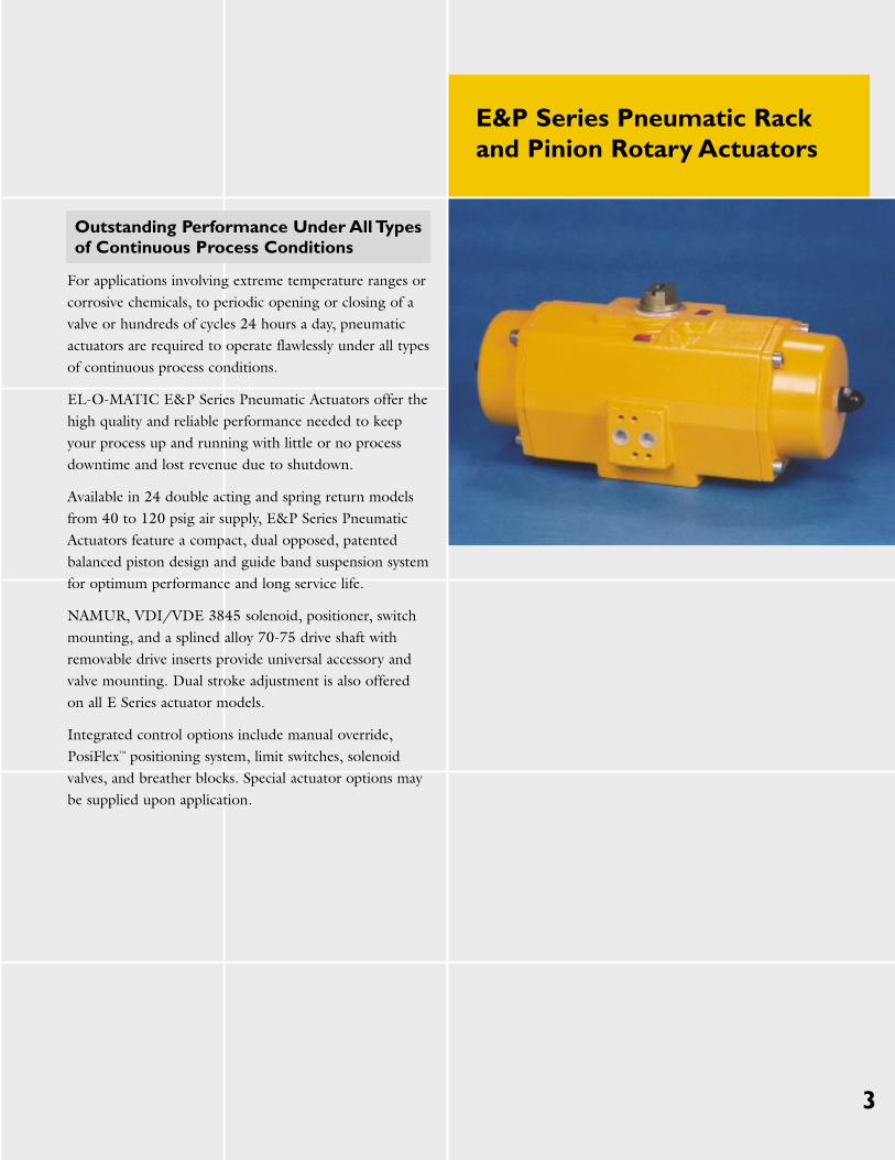
Outstanding Performance Under All Types of Continuous Process Conditions
For applications involving extreme temperature ranges orcorrosive chemicals, to periodic opening or closing of avalve or hundreds of cycles 24 hours a day, pneumaticactuators are required to operate flawlessly under all typesof continuous process conditions.
EL-O-MATIC E&P Series Pneumatic Actuators offer thehigh quality and reliable performance needed to keepyour process up and running with little or no processdowntime and lost revenue due to shutdown.
Available in 24 double acting and spring return modelsfrom 40 to 120 psig air supply, E&P Series PneumaticActuators feature a compact, dual opposed, patentedbalanced piston design and guide band suspension systemfor optimum performance and long service life.
NAMUR, VDI/VDE 3845 solenoid, positioner, switchmounting, and a splined alloy 70-75 drive shaft withremovable drive inserts provide universal accessory andvalve mounting. Dual stroke adjustment is also offered on all E Series actuator models.
Integrated control options include manual override, PosiFlex™ positioning system, limit switches, solenoidvalves, and breather blocks. Special actuator options maybe supplied upon application.
E&P Series Pneumatic Rackand Pinion Rotary Actuators
4
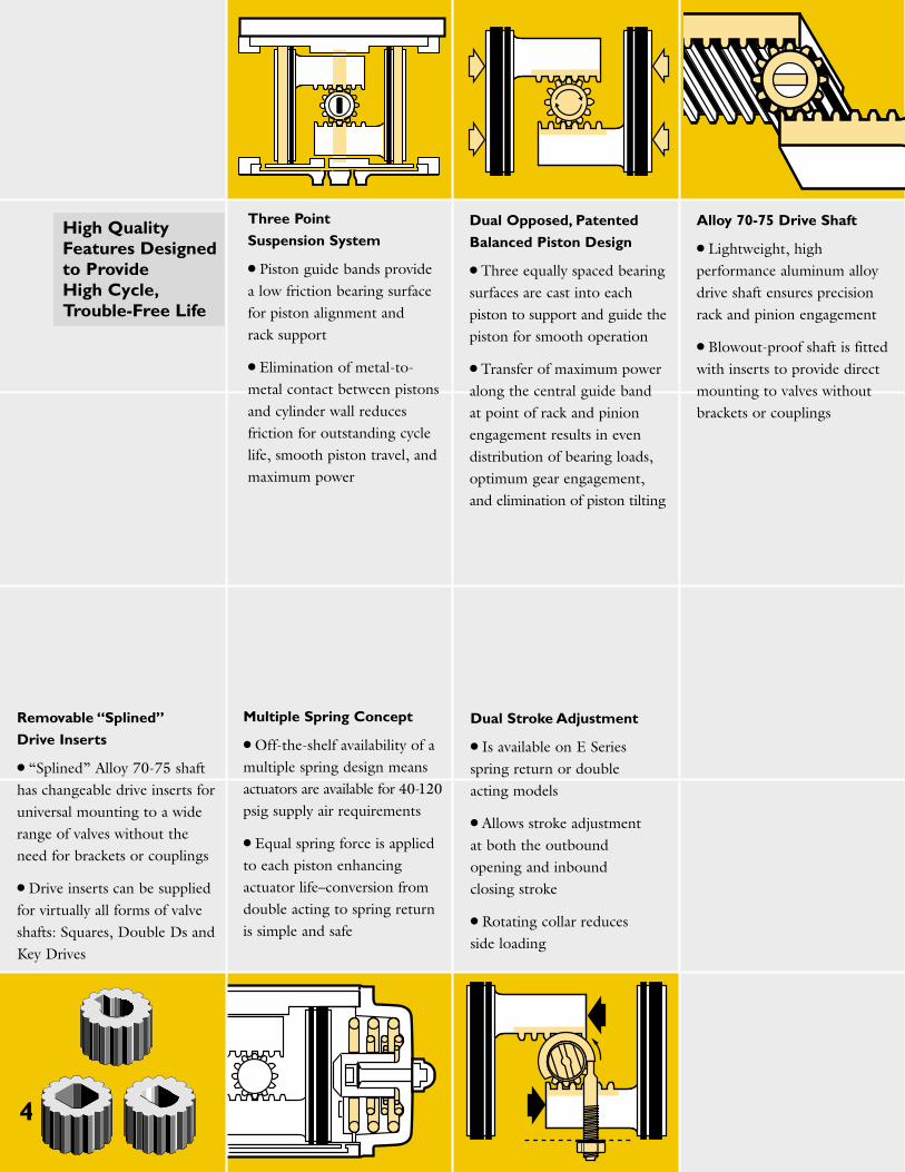
Dual Stroke Adjustment
● Is available on E Seriesspring return or doubleacting models
● Allows stroke adjustmentat both the outboundopening and inboundclosing stroke
● Rotating collar reducesside loading
Three Point
Suspension System
● Piston guide bands providea low friction bearing surfacefor piston alignment and rack support
● Elimination of metal-to-metal contact between pistonsand cylinder wall reducesfriction for outstanding cyclelife, smooth piston travel, andmaximum power
Dual Opposed, Patented
Balanced Piston Design
● Three equally spaced bearingsurfaces are cast into eachpiston to support and guide thepiston for smooth operation
● Transfer of maximum poweralong the central guide bandat point of rack and pinionengagement results in evendistribution of bearing loads,optimum gear engagement,and elimination of piston tilting
Alloy 70-75 Drive Shaft
● Lightweight, highperformance aluminum alloydrive shaft ensures precisionrack and pinion engagement
● Blowout-proof shaft is fittedwith inserts to provide directmounting to valves withoutbrackets or couplings
Removable “Splined”
Drive Inserts
● “Splined” Alloy 70-75 shafthas changeable drive inserts foruniversal mounting to a widerange of valves without theneed for brackets or couplings
● Drive inserts can be suppliedfor virtually all forms of valveshafts: Squares, Double Ds andKey Drives
Multiple Spring Concept
● Off-the-shelf availability of amultiple spring design meansactuators are available for 40-120psig supply air requirements
● Equal spring force is appliedto each piston enhancingactuator life–conversion fromdouble acting to spring returnis simple and safe
High Quality Features Designed to Provide High Cycle,Trouble-Free Life
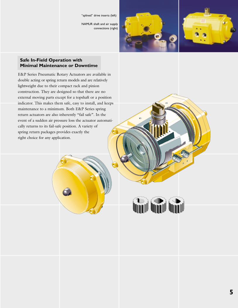
“splined” drive inserts (left)
NAMUR shaft and air supplyconnections (right)
Safe In-Field Operation with Minimal Maintenance or Downtime
E&P Series Pneumatic Rotary Actuators are available indouble acting or spring return models and are relativelylightweight due to their compact rack and pinionconstruction. They are designed so that there are noexternal moving parts except for a topshaft or a positionindicator. This makes them safe, easy to install, and keepsmaintenance to a minimum. Both E&P Series springreturn actuators are also inherently “fail safe”. In theevent of a sudden air pressure loss the actuator automati-cally returns to its fail-safe position. A variety of spring return packages provides exactly the right choice for any application.
5
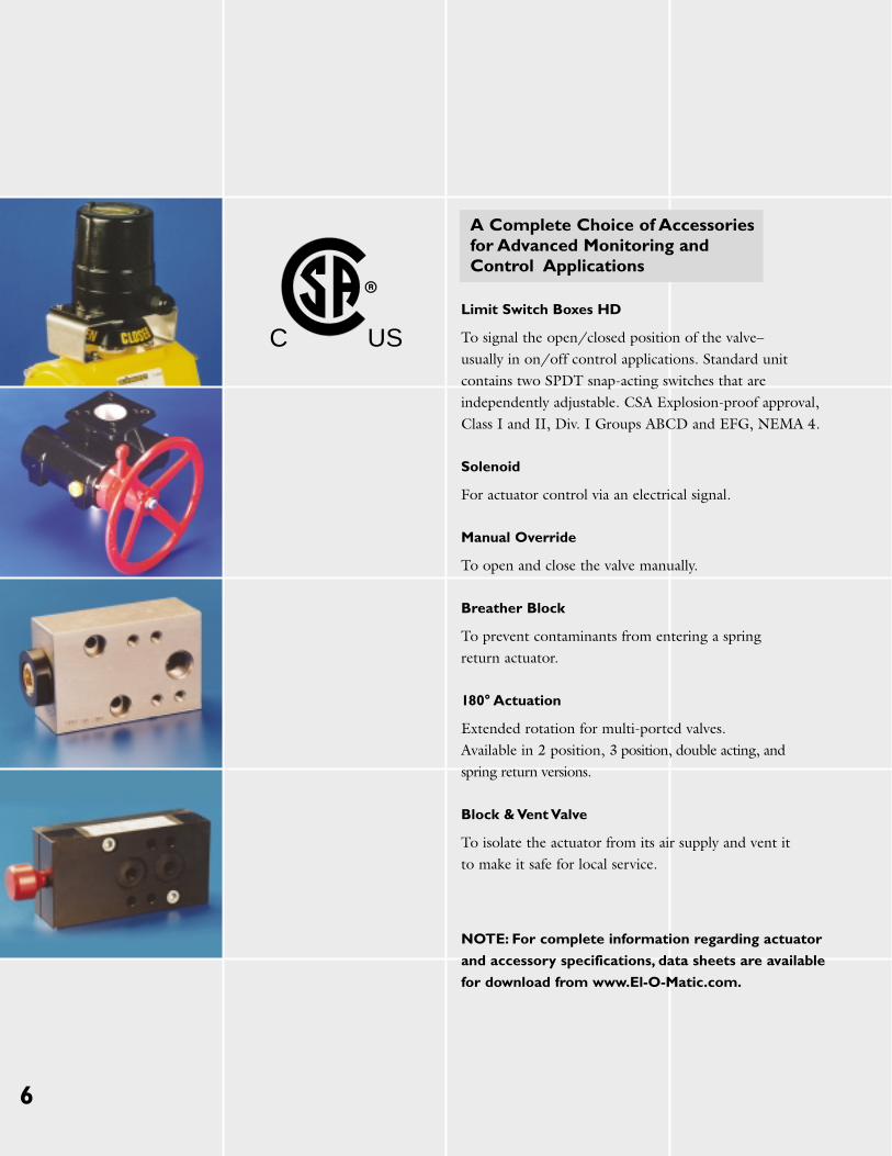
A Complete Choice of Accessories for Advanced Monitoring and Control Applications
Limit Switch Boxes HD
To signal the open/closed position of the valve–usually in on/off control applications. Standard unitcontains two SPDT snap-acting switches that are independently adjustable. CSA Explosion-proof approval,Class I and II, Div. I Groups ABCD and EFG, NEMA 4.
Solenoid
For actuator control via an electrical signal.
Manual Override
To open and close the valve manually.
Breather Block
To prevent contaminants from entering a spring return actuator.
180° Actuation
Extended rotation for multi-ported valves. Available in 2 position, 3 position, double acting, and spring return versions.
Block & Vent Valve
To isolate the actuator from its air supply and vent it to make it safe for local service.
NOTE: For complete information regarding actuator
and accessory specifications, data sheets are available
for download from www.El-O-Matic.com.
6
C US
7
SpecificationsOperating Pressure
(90° models) 40 to 120 psig (spring return)20 to 120 psig (double acting)
(180° models) 80 psig max. pressure (except E12)Temperature (standard) -4 to 175°F (-20 to 80°C)
(optional) -4 to 250°F (-20 to 121°C)-40 to 175°F (-40 to 80°C)
Media Air dry or lubricated; noncorrosive gasRotation 91.5° (96°-3°clockwise to +3°counterclockwise–DSA model)
Materials casing: aluminum alloyshaft: 70-75 aluminum alloy
Finish Polyester non-TGIC based powder coatingLife Up to one million cycles, depending on application
Available Models and Sizing Data
E&P Series Pneumatic Rotary Actuators are available in twelve (12) single acting and twelve (12) double acting models.
180° Dual Stroke Adjustment (DSA), Caustic SodaResistant (CSR) high or low temperature and fast-actingmodels are also available.
Complete sizing data for all major valve manufacturers ison file and available from EL-O-MATIC’s in-housedatabase to ensure proper selection of the right actuatorfor the right valve.
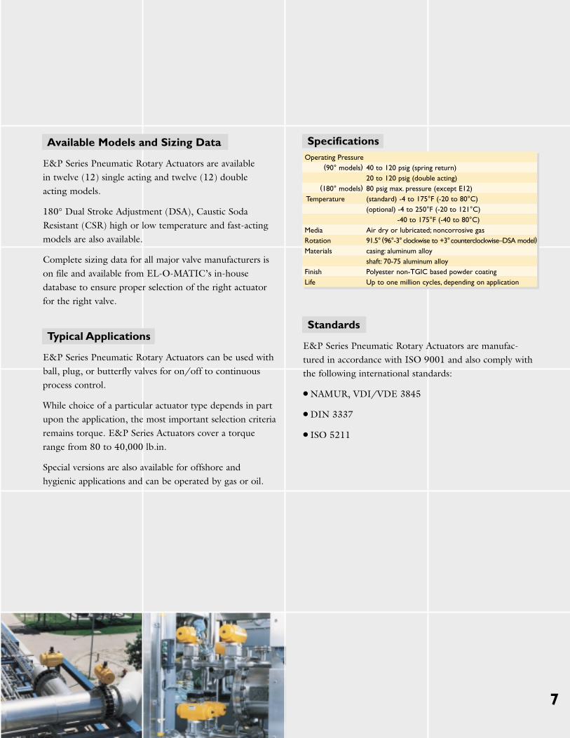
Typical Applications
E&P Series Pneumatic Rotary Actuators can be used withball, plug, or butterfly valves for on/off to continuousprocess control.
While choice of a particular actuator type depends in partupon the application, the most important selection criteriaremains torque. E&P Series Actuators cover a torquerange from 80 to 40,000 lb.in.
Special versions are also available for offshore andhygienic applications and can be operated by gas or oil.
Standards
E&P Series Pneumatic Rotary Actuators are manufac-tured in accordance with ISO 9001 and also comply withthe following international standards:
● NAMUR, VDI/VDE 3845
● DIN 3337
● ISO 5211
8
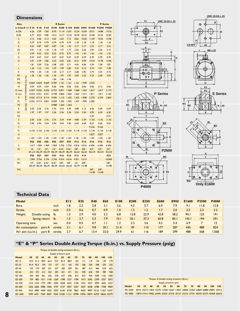
DimensionsDim. E Series P Series
in inchesE 12 E 25 E 40 E 65 E100 E200 E 350 E600 E950 E1600 P2500 P4000
A DA 6.26 7.09 7.83 8.70 11.14 12.01 15.24 16.69 20.31 14.88 19.76
B SR 6.77 8.03 9.80 10.51 14.17 15.24 18.78 20.35 25.08 22.44 32.83
C 3.15 3.66 4.13 4.65 5.63 7.13 8.66 10.20 11.69 14.02 14.96
D 0.79 0.79 0.79 0.79 0.79 0.79 1.18 1.18 1.18 1.18 1.18
E 0.63 0.87 0.87 0.87 1.42 1.42 2.17 2.17 2.52 2.17 2.52
E2 0.91 1.18 1.18 1.18 1.77 1.77 2.56 2.56 2.95 2.56 3.15
F 0.39 0.55 0.55 0.55 0.75 0.75 1.42 1.42 1.42 1.42 1.42
G 0.47 0.47 0.47 0.47 0.47 0.47 0.39 0.39 0.39 0.39 0.39
H 2.91 3.39 3.86 4.25 5.04 6.81 8.15 9.09 10.43 13.78 14.96
I 1.81 2.09 2.26 2.48 2.87 3.71 4.45 4.96 5.59 7.28 7.87
J 1.26 1.32 1.54 1.59 1.99 2.85 3.33 4.15 4.74 7.01 7.48
K 0.94 1.30 1.30 1.50 2.17 2.17 2.68 2.95 3.74 3.35 4.72
M1 1.36 1.36 1.36 1.36 1.97 1.97 2.05 2.52 3.23 2.60 3.03
M2 - - - 1.06 1.46 1.46 - - - - -
M3 0.669 0.669 0.669 0.787 1.161 1.161 1.161 1.949 2.303 - -
N 0.04 0.04 0.04 0.06 0.06 0.06 0.06 0.06 0.06 0.12 0.06
O max. 0.437 0.556 0.556 0.753 0.871 1.068 1.068 1.424 1.817 1.817 2.173
O min. 0.433 0.551 0.551 0.748 0.866 1.063 1.063 1.417 1.811 1.811 2.165
P 0.555 0.713 0.713 0.992 1.110 1.425 1.425 1.898 2.370 2.370 2.843
P1 0.555 0.713 0.831 0.909 1.303 1.303 1.437 1.909 2.382 - -
P2 - - - 0.988 1.264 1.264 - - - - -
R 2.05 2.56 2.76 2.76 3.54 4.49 4.88 5.12 6.06 6.69 6.69
R1 1.97 1.97 1.97 2.36 2.36 2.36 3.54 3.54 4.92 6.30 6.30
R2 - - - - - - - - 5.20 - 10.31
S 2.05 2.56 2.76 2.76 3.54 4.49 4.88 5.59 11.02 11.42 11.42
S1 3.94 3.94 3.94 3.94 3.94 3.94 6.69 6.69 8.27 9.65 9.65
T - - - - - - - - 9.236 9.236 -
T1 3.150 3.150 3.150 3.150 3.150 3.150 5.118 5.118 5.118 5.118 5.118
U - - - - - - - - 3.827 3.827 -
U1 1.181 1.181 1.181 1.181 1.181 1.181 1.181 1.181 1.181 1.181 1.181
F03 F05 F05 F05 F07 F07 F12 F14 F16 F16 F16
V 1.417 1.969 1.969 1.969 2.756 2.756 4.016 4.016 6.496 6.496 6.496
W 10- 1/4"- 1/4"- 1/4"- 5/16"- 5/16"- 3/8"- 3/8"- 3/4"- 3/4"- 3/4"-24 x,31 20x.39 20x.39 20x.39 18x.39 18x.39 16x.63 16x.63 10x1.14 10x1.14 10x1.14
F05 F07 F07 F07 F10 F10 F12 F14 - - F25
V1 1.969 2.756 2.756 2.756 4.016 4.016 4.921 5.512 - - 10.000
W1 1/4"- 5/16"- 5/16"- 5/16"- 3/8"- 3/8"- 1/2"- 5/8"- 5/8"-20x.39 18x.39 18x.39 18x.39 16x.63 16x.63 13x.79 11x.98 - - 11x.98
W2 - - - - - 5/8"- 5/8"-11x.98 11x.98
For E12 dimensions see A
1.103.102
Technical DataModel E12 E25 E40 E65 E100 E200 E350 E600 E950 E1600 P2500 P4000Bore inch 1.8 2.2 2.8 3.1 3.6 4.3 5.7 6.9 7.9 9.1 11.8 12.8Stroke inch 0.5 0.6 0.7 0.9 1.0 1.5 1.5 1.7 2.0 2.5 2.2 3.2Weight: Double acting lb. 1.3 2.9 4.0 5.3 6.8 12.8 22.9 42.8 58.2 94.1 125 191
Spring return lb. 1.5 3.7 5.3 7.9 10.1 20.1 37.3 60.8 85.1 145.1 194 291Operating time sec. 0.4 0.5 0.7 1.1 1.2 2.3 3.6 4.5 5.4 6.9 7 12Air consumption port A stroke 3.1 6.1 9.8 20.1 21.4 49 110 177 287 445 488 824At1 atm (cu./in.) port B stroke 3.7 6.7 13.4 22.0 29.9 61 116 189 299 488 568 1.068
Torque of double acting actuators (lb.in.)
Supply pressure (psi)
Model 30 35 40 45 50 55 60 70 75 80 90 100 120
ED 12 43.9 51.4 58.9 66.4 73.9 81.4 88.9 104 111 119 134 149 179
ED 25 81.4 95.3 109 123 137 151 165 193 206 220 248 276 332
ED 40 153 179 205 231 257 283 309 361 387 413 466 518 622
ED 65 233 272 312 352 392 431 471 551 590 630 709 789 948
ED 100 344 402 461 520 578 637 696 813 872 930 1048 1165 1400
ED 200 754 883 1011 1140 1269 1398 1527 1784 1913 2042 2299 2557 3072
ED 350 1310 1534 1757 1981 2205 2428 2652 3100 3323 3547 3994 4442 5337
ED 600 2226 2606 2986 3366 3747 4127 4507 5267 5647 6028 6788 7548 9069
ED 950 3323 3890 4458 5025 5593 6160 6728 7862 8430 8997 10132 11267 13537
ED 1600 5493 6431 7369 8307 9245 10183 11121 12998 13936 14874 16750 18626 22379
Torque of double acting actuators (lb.in.)
Supply pressure (psi)
Model 30 35 40 45 50 55 60 70 75 80 90 100 120
PD 2500 8774 10273 11825 13270 14768 16267 17847 20858 22363 23869 26880 29891 35912
PD 4000 1487417414 19962 22495 25035 27576 30127 35210 37751 40293 45375 50458 60623
W2
U
TS
R2
Only E1600
S
O R
W1W
P +.02
M1M2
K
N ±.02
E SeriesP1P2
H
4
I M6 x 12
241/4 NPT
A
32
B
UNC 10-24 x .31
U1
T1 UNC 10-24 x .31
R1
4S1
G
D
C
J
E2
FE
M1
K
TV
N ±.02
P Series
BA
P +.02
W2
O U R
WS
P2500
W1
R R2
P4000
W
V1 V
V1V
“E” & “P” Series Double Acting Torque (lb.in.) vs. Supply Pressure (psig)
9
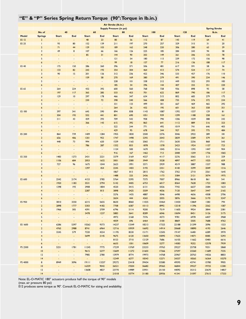
Note: EL-O-MATIC 180° actuators produce half the torque of 90° models(max. air pressure 80 psi)E12 produces same torque as 90°. Consult EL-O-MATIC for sizing and availability.
“E” & “P” Series Spring Return Torque (90°:Torque in lb.in.)Air Stroke (lb.in.)
Supply Pressure (in psi) Spring Stroke
No. of 40 60 80 100 120 lb.in.
Model Springs Start End Start End Start End Start End Start End Start End
ES 12 2 - - 48 23 80 56 112 87 143 119 64 41
ES 25 1 93 80 152 139 211 197 270 257 329 315 31 20
2 71 44 129 103 189 162 248 220 306 280 63 39
3 49 8 107 66 166 126 225 185 284 243 94 58
4 - - 85 31 144 90 202 149 261 206 125 78
5 - - - - 121 54 180 113 239 172 156 98
6 - - - - 99 18 157 77 216 136 188 117
ES 40 1 175 150 286 260 396 371 506 481 617 591 58 36
2 133 82 243 193 354 304 464 413 574 524 117 74
3 90 15 201 126 312 236 422 346 533 457 176 110
4 - - 159 58 270 169 380 279 491 390 234 146
5 - - - - 228 101 338 212 449 322 293 183
6 - - - - 185 34 296 144 407 255 351 220
ES 65 1 264 224 432 392 600 560 768 728 936 898 93 58
2 197 117 365 285 533 453 701 622 869 790 186 117
3 129 10 297 178 466 347 634 515 802 683 279 175
4 - - 230 72 398 240 566 408 735 576 372 234
5 - - - - 331 133 499 301 667 469 465 292
6 - - - - 264 26 432 195 601 363 558 351
ES 100 1 397 341 645 590 894 838 1143 1087 1392 1337 129 81
2 304 192 552 441 801 690 1051 939 1299 1188 258 161
3 211 43 459 293 709 542 958 790 1206 1039 388 242
4 - - 366 143 615 392 863 641 1112 889 516 323
5 - - - - 522 244 771 492 1019 741 646 403
6 - - - - 429 95 678 344 927 593 775 484
ES 200 1 864 739 1409 1284 1955 1830 2500 2376 3046 2922 289 181
2 656 406 1201 952 1747 1498 2292 2043 2839 2589 579 361
3 448 73 994 620 1539 1165 2065 1711 2630 2256 868 543
4 - - 786 287 1332 833 1878 1378 2423 1924 1157 723
5 - - - - 1124 500 1670 1045 2216 1592 1447 904
6 - - - - 916 167 1462 713 2008 1259 1736 1065
ES 350 1 1483 1273 2431 2221 3379 3169 4327 4117 5276 5065 513 329
2 1106 684 2053 1632 3001 2580 3949 3528 4897 4477 1025 659
3 727 96 1675 1044 2623 1991 3571 2939 4519 3887 1537 988
4 - - 1297 454 2245 1403 3192 2351 4140 3299 2049 1316
5 - - - - 1867 813 2815 1762 3762 2710 2561 1645
6 - - - - 1488 225 2436 1173 3384 2121 3074 1975
ES 600 1 2542 2174 4153 3785 5764 5395 7375 7007 8966 8618 861 541
2 1920 1183 3531 2794 5142 4405 6753 6017 8364 7628 1723 1083
3 1298 193 2908 1804 4520 3415 6131 5026 7742 6637 2584 1623
4 - - 2287 813 3898 2425 5509 4036 7120 5647 3447 2165
5 - - - - 3276 1435 4887 3046 6498 4656 4308 2706
6 - - - - 2654 444 4265 2055 5876 3666 5170 3247
ES 950 1 3810 3250 6215 5655 8620 8060 11025 10464 13430 12869 1282 794
2 2898 1777 5303 4182 7708 6587 10113 8992 12518 11396 2562 1587
3 1966 305 4391 2709 6796 5114 9200 7519 11605 9924 3844 2381
4 - - 3478 1237 5883 3641 8289 6046 10694 8451 5126 3175
5 - - - - 4972 2168 7376 4573 9781 6978 6407 3968
6 - - - - 4059 696 6464 3100 8869 5505 7688 4762
ES 1600 1 6286 5397 10262 9373 14237 13349 18213 17325 22188 21299 2096 1323
2 4765 2988 8741 6964 12716 10939 16692 14914 20668 18890 4193 2646
3 3245 579 7220 4554 11195 8530 15171 12505 19147 16481 6289 3970
4 - - 5699 2145 9675 6120 13650 10095 17625 14071 8385 5293
5 - - - - 8153 3710 12129 7686 16105 11662 10481 6616
6 - - - - 6633 1301 10609 5277 14583 9252 12578 7939
PS 2500 8 5251 1781 11245 7775 17239 13769 23233 19763 29227 25758 9351 5868
10 - - 9615 5277 15609 11272 21603 17266 27597 23260 11689 7335
12 - - 7985 2780 13979 8774 19973 14768 25967 20763 14026 8803
14 - - - - 12349 6277 18343 12271 24337 18265 16364 10270
PS 4000 8 8949 3096 19111 13257 29272 23418 39434 33580 49595 43741 15780 9905
10 - - 16359 9042 26521 19204 36682 29365 46844 39527 19725 12381
12 - - 13608 4827 23770 14989 33931 25150 44092 35312 23670 14857
14 - - - - 21018 10774 31180 20936 41341 31097 27615 17333
10
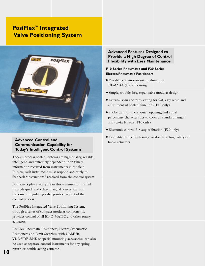
PosiFlex™ IntegratedValve Positioning System
Advanced Control and Communication Capability for Today’s Intelligent Control Systems
Today’s process control systems are high quality, reliable,intelligent–and extremely dependent upon timelyinformation received from instruments in the field.In turn, each instrument must respond accurately tofeedback “instructions” received from the control system.
Positioners play a vital part in this communications linkthrough quick and efficient signal conversion, andresponse in regulating valve position as part of the control process.
The PosiFlex Integrated Valve Positioning System,through a series of compact modular components,provides control of all EL-O-MATIC and other rotaryactuators.
PosiFlex Pneumatic Positioners, Electro/PneumaticPositioners and Limit Switches, with NAMUR,VDI/VDE 3845 or special mounting accessories, can alsobe used as separate control instruments for any springreturn or double acting actuator.
Advanced Features Designed toProvide a High Degree of ControlFlexibility with Less Maintenance
F10 Series Pneumatic and F20 Series
Electro/Pneumatic Positioners
● Durable, corrosion-resistant aluminum NEMA 4X (IP65) housing
● Simple, trouble-free, expandable modular design
● External span and zero setting for fast, easy setup and adjustment of control functions (F10 only)
● 3 lobe cam for linear, quick opening, and equal percentage characteristics to cover all standard ranges and stroke lengths (F10 only)
● Electronic control for easy calibration (F20 only)
● Flexibility for use with single or double acting rotary or linear actuators
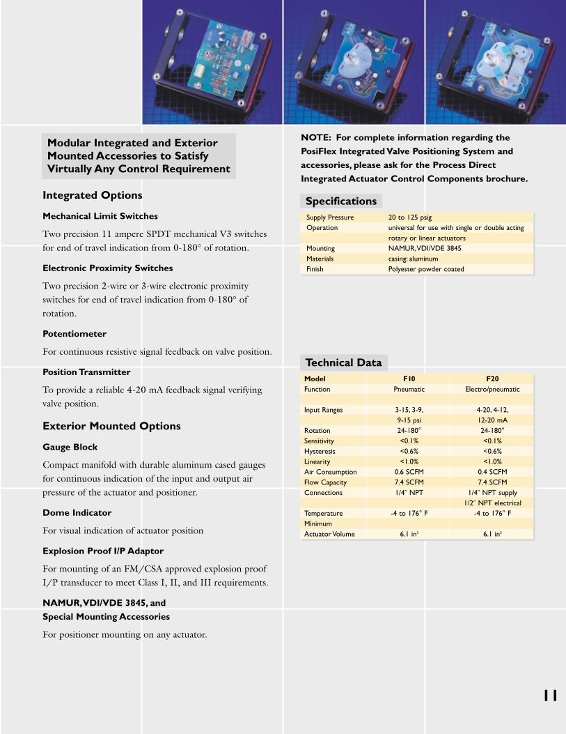
Modular Integrated and Exterior Mounted Accessories to Satisfy Virtually Any Control Requirement
Integrated Options
Mechanical Limit Switches
Two precision 11 ampere SPDT mechanical V3 switchesfor end of travel indication from 0-180° of rotation.
Electronic Proximity Switches
Two precision 2-wire or 3-wire electronic proximityswitches for end of travel indication from 0-180° ofrotation.
Potentiometer
For continuous resistive signal feedback on valve position.
Position Transmitter
To provide a reliable 4-20 mA feedback signal verifyingvalve position.
Exterior Mounted Options
Gauge Block
Compact manifold with durable aluminum cased gaugesfor continuous indication of the input and output airpressure of the actuator and positioner.
Dome Indicator
For visual indication of actuator position
Explosion Proof I/P Adaptor
For mounting of an FM/CSA approved explosion proofI/P transducer to meet Class I, II, and III requirements.
NAMUR,VDI/VDE 3845, and
Special Mounting Accessories
For positioner mounting on any actuator.
11
NOTE: For complete information regarding the
PosiFlex Integrated Valve Positioning System and
accessories, please ask for the Process Direct
Integrated Actuator Control Components brochure.
SpecificationsSupply Pressure 20 to 125 psigOperation universal for use with single or double acting
rotary or linear actuatorsMounting NAMUR,VDI/VDE 3845Materials casing: aluminum Finish Polyester powder coated
Technical DataModel F10 F20Function Pneumatic Electro/pneumatic
Input Ranges 3-15, 3-9, 4-20, 4-12,9-15 psi 12-20 mA
Rotation 24-180° 24-180°Sensitivity <0.1% <0.1%Hysteresis <0.6% <0.6%Linearity <1.0% <1.0%Air Consumption 0.6 SCFM 0.4 SCFMFlow Capacity 7.4 SCFM 7.4 SCFMConnections 1/4˝ NPT 1/4˝ NPT supply
1/2˝ NPT electricalTemperature -4 to 176° F -4 to 176° FMinimumActuator Volume 6.1 in3 6.1 in3
12
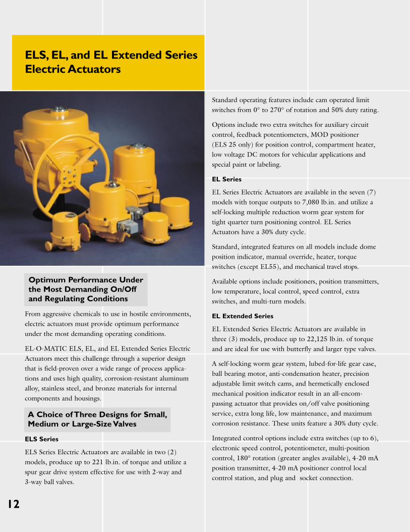
ELS, EL, and EL Extended SeriesElectric Actuators
Optimum Performance Under the Most Demanding On/Off and Regulating Conditions
From aggressive chemicals to use in hostile environments,electric actuators must provide optimum performanceunder the most demanding operating conditions.
EL-O-MATIC ELS, EL, and EL Extended Series ElectricActuators meet this challenge through a superior designthat is field-proven over a wide range of process applica-tions and uses high quality, corrosion-resistant aluminumalloy, stainless steel, and bronze materials for internalcomponents and housings.
A Choice of Three Designs for Small,Medium or Large-Size Valves
ELS Series
ELS Series Electric Actuators are available in two (2)models, produce up to 221 lb.in. of torque and utilize aspur gear drive system effective for use with 2-way and 3-way ball valves.
Standard operating features include cam operated limitswitches from 0° to 270° of rotation and 50% duty rating.
Options include two extra switches for auxiliary circuitcontrol, feedback potentiometers, MOD positioner (ELS 25 only) for position control, compartment heater,low voltage DC motors for vehicular applications andspecial paint or labeling.
EL Series
EL Series Electric Actuators are available in the seven (7)models with torque outputs to 7,080 lb.in. and utilize aself-locking multiple reduction worm gear system fortight quarter turn positioning control. EL SeriesActuators have a 30% duty cycle.
Standard, integrated features on all models include domeposition indicator, manual override, heater, torqueswitches (except EL55), and mechanical travel stops.
Available options include positioners, position transmitters,low temperature, local control, speed control, extraswitches, and multi-turn models.
EL Extended Series
EL Extended Series Electric Actuators are available inthree (3) models, produce up to 22,125 lb.in. of torqueand are ideal for use with butterfly and larger type valves.
A self-locking worm gear system, lubed-for-life gear case,ball bearing motor, anti-condensation heater, precisionadjustable limit switch cams, and hermetically enclosedmechanical position indicator result in an all-encom-passing actuator that provides on/off valve positioningservice, extra long life, low maintenance, and maximumcorrosion resistance. These units feature a 30% duty cycle.
Integrated control options include extra switches (up to 6),electronic speed control, potentiometer, multi-positioncontrol, 180° rotation (greater angles available), 4-20 mAposition transmitter, 4-20 mA positioner control localcontrol station, and plug and socket connection.
EL Extended Series
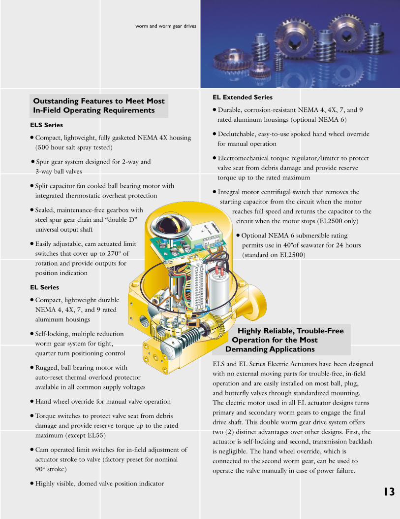
● Durable, corrosion-resistant NEMA 4, 4X, 7, and 9 rated aluminum housings (optional NEMA 6)
● Declutchable, easy-to-use spoked hand wheel override for manual operation
● Electromechanical torque regulator/limiter to protect valve seat from debris damage and provide reserve torque up to the rated maximum
● Integral motor centrifugal switch that removes the starting capacitor from the circuit when the motor
reaches full speed and returns the capacitor to thecircuit when the motor stops (EL2500 only)
● Optional NEMA 6 submersible rating permits use in 40”of seawater for 24 hours(standard on EL2500)
Highly Reliable, Trouble-FreeOperation for the Most
Demanding Applications
ELS and EL Series Electric Actuators have been designedwith no external moving parts for trouble-free, in-fieldoperation and are easily installed on most ball, plug, and butterfly valves through standardized mounting. The electric motor used in all EL actuator designs turnsprimary and secondary worm gears to engage the finaldrive shaft. This double worm gear drive system offerstwo (2) distinct advantages over other designs. First, theactuator is self-locking and second, transmission backlashis negligible. The hand wheel override, which isconnected to the second worm gear, can be used tooperate the valve manually in case of power failure.
13
worm and worm gear drives
Outstanding Features to Meet Most In-Field Operating Requirements
ELS Series
● Compact, lightweight, fully gasketed NEMA 4X housing(500 hour salt spray tested)
● Spur gear system designed for 2-way and 3-way ball valves
● Split capacitor fan cooled ball bearing motor with integrated thermostatic overheat protection
● Sealed, maintenance-free gearbox with steel spur gear chain and “double-D” universal output shaft
● Easily adjustable, cam actuated limit switches that cover up to 270° of rotation and provide outputs for position indication
EL Series
● Compact, lightweight durable NEMA 4, 4X, 7, and 9 rated aluminum housings
● Self-locking, multiple reduction worm gear system for tight, quarter turn positioning control
● Rugged, ball bearing motor with auto-reset thermal overload protectoravailable in all common supply voltages
● Hand wheel override for manual valve operation
● Torque switches to protect valve seat from debris damage and provide reserve torque up to the rated maximum (except EL55)
● Cam operated limit switches for in-field adjustment of actuator stroke to valve (factory preset for nominal 90° stroke)
● Highly visible, domed valve position indicator
14
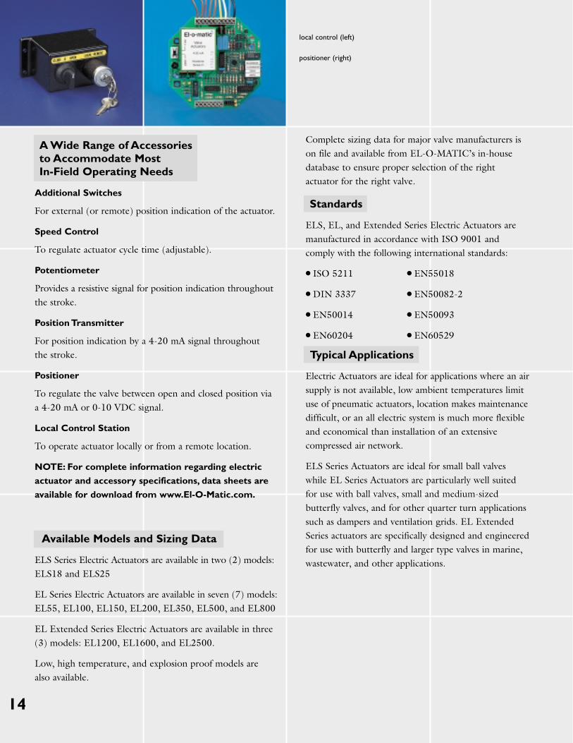
local control (left)
positioner (right)
A Wide Range of Accessories to Accommodate Most In-Field Operating Needs
Additional Switches
For external (or remote) position indication of the actuator.
Speed Control
To regulate actuator cycle time (adjustable).
Potentiometer
Provides a resistive signal for position indication throughoutthe stroke.
Position Transmitter
For position indication by a 4-20 mA signal throughout the stroke.
Positioner
To regulate the valve between open and closed position viaa 4-20 mA or 0-10 VDC signal.
Local Control Station
To operate actuator locally or from a remote location.
NOTE: For complete information regarding electric
actuator and accessory specifications, data sheets are
available for download from www.El-O-Matic.com.
Available Models and Sizing Data
ELS Series Electric Actuators are available in two (2) models:ELS18 and ELS25
EL Series Electric Actuators are available in seven (7) models:EL55, EL100, EL150, EL200, EL350, EL500, and EL800
EL Extended Series Electric Actuators are available in three(3) models: EL1200, EL1600, and EL2500.
Low, high temperature, and explosion proof models are also available.
Complete sizing data for major valve manufacturers ison file and available from EL-O-MATIC’s in-housedatabase to ensure proper selection of the rightactuator for the right valve.
Standards
ELS, EL, and Extended Series Electric Actuators aremanufactured in accordance with ISO 9001 andcomply with the following international standards:
● ISO 5211 ● EN55018
● DIN 3337 ● EN50082-2
● EN50014 ● EN50093
● EN60204 ● EN60529
Typical Applications
Electric Actuators are ideal for applications where an airsupply is not available, low ambient temperatures limituse of pneumatic actuators, location makes maintenancedifficult, or an all electric system is much more flexibleand economical than installation of an extensivecompressed air network.
ELS Series Actuators are ideal for small ball valves while EL Series Actuators are particularly well suited for use with ball valves, small and medium-sizedbutterfly valves, and for other quarter turn applicationssuch as dampers and ventilation grids. EL ExtendedSeries actuators are specifically designed and engineeredfor use with butterfly and larger type valves in marine,wastewater, and other applications.
15
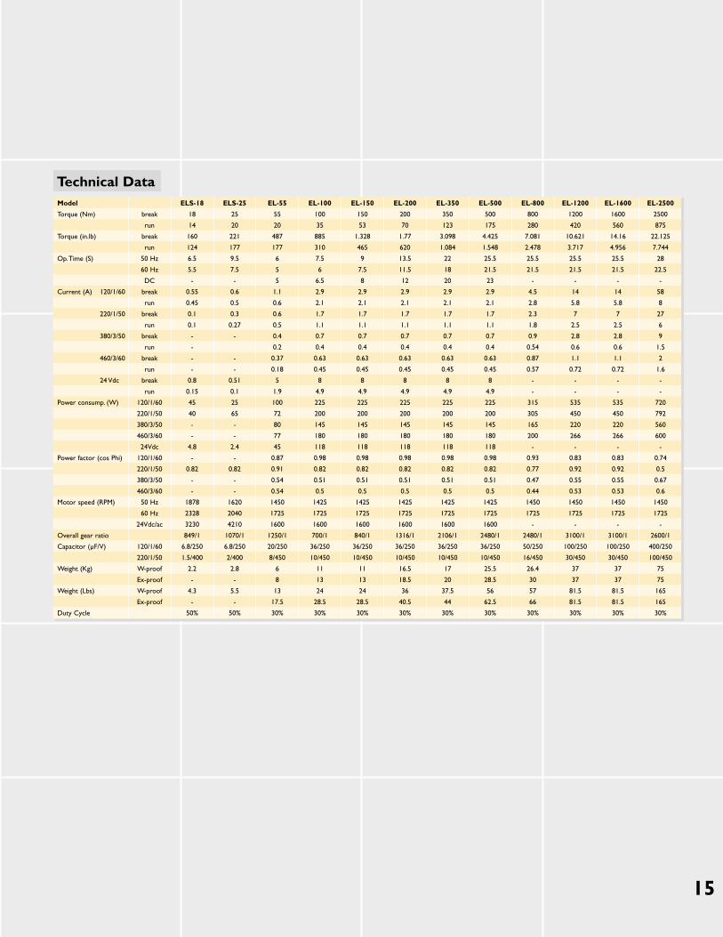
Technical DataModel ELS-18 ELS-25 EL-55 EL-100 EL-150 EL-200 EL-350 EL-500 EL-800 EL-1200 EL-1600 EL-2500
Torque (Nm) break 18 25 55 100 150 200 350 500 800 1200 1600 2500
run 14 20 20 35 53 70 123 175 280 420 560 875
Torque (in.lb) break 160 221 487 885 1.328 1.77 3.098 4.425 7.081 10.621 14.16 22.125
run 124 177 177 310 465 620 1.084 1.548 2.478 3.717 4.956 7.744
Op.Time (S) 50 Hz 6.5 9.5 6 7.5 9 13.5 22 25.5 25.5 25.5 25.5 28
60 Hz 5.5 7.5 5 6 7.5 11.5 18 21.5 21.5 21.5 21.5 22.5
DC - - 5 6.5 8 12 20 23 - - - -
Current (A) 120/1/60 break 0.55 0.6 1.1 2.9 2.9 2.9 2.9 2.9 4.5 14 14 58
run 0.45 0.5 0.6 2.1 2.1 2.1 2.1 2.1 2.8 5.8 5.8 8
220/1/50 break 0.1 0.3 0.6 1.7 1.7 1.7 1.7 1.7 2.3 7 7 27
run 0.1 0.27 0.5 1.1 1.1 1.1 1.1 1.1 1.8 2.5 2.5 6
380/3/50 break - - 0.4 0.7 0.7 0.7 0.7 0.7 0.9 2.8 2.8 9
run - 0.2 0.4 0.4 0.4 0.4 0.4 0.54 0.6 0.6 1.5
460/3/60 break - - 0.37 0.63 0.63 0.63 0.63 0.63 0.87 1.1 1.1 2
run - - 0.18 0.45 0.45 0.45 0.45 0.45 0.57 0.72 0.72 1.6
24 Vdc break 0.8 0.51 5 8 8 8 8 8 - - - -
run 0.15 0.1 1.9 4.9 4.9 4.9 4.9 4.9 - - - -
Power consump. (W) 120/1/60 45 25 100 225 225 225 225 225 315 535 535 720
220/1/50 40 65 72 200 200 200 200 200 305 450 450 792
380/3/50 - - 80 145 145 145 145 145 165 220 220 560
460/3/60 - - 77 180 180 180 180 180 200 266 266 600
24Vdc 4.8 2.4 45 118 118 118 118 118 - - - -
Power factor (cos Phi) 120/1/60 - - 0.87 0.98 0.98 0.98 0.98 0.98 0.93 0.83 0.83 0.74
220/1/50 0.82 0.82 0.91 0.82 0.82 0.82 0.82 0.82 0.77 0.92 0.92 0.5
380/3/50 - - 0.54 0.51 0.51 0.51 0.51 0.51 0.47 0.55 0.55 0.67
460/3/60 - - 0.54 0.5 0.5 0.5 0.5 0.5 0.44 0.53 0.53 0.6
Motor speed (RPM) 50 Hz 1878 1620 1450 1425 1425 1425 1425 1425 1450 1450 1450 1450
60 Hz 2328 2040 1725 1725 1725 1725 1725 1725 1725 1725 1725 1725
24Vdc/ac 3230 4210 1600 1600 1600 1600 1600 1600 - - - -
Overall gear ratio 849/1 1070/1 1250/1 700/1 840/1 1316/1 2106/1 2480/1 2480/1 3100/1 3100/1 2600/1
Capacitor (µF/V) 120/1/60 6.8/250 6.8/250 20/250 36/250 36/250 36/250 36/250 36/250 50/250 100/250 100/250 400/250
220/1/50 1.5/400 2/400 8/450 10/450 10/450 10/450 10/450 10/450 16/450 30/450 30/450 100/450
Weight (Kg) W-proof 2.2 2.8 6 11 11 16.5 17 25.5 26.4 37 37 75
Ex-proof - - 8 13 13 18.5 20 28.5 30 37 37 75
Weight (Lbs) W-proof 4.3 5.5 13 24 24 36 37.5 56 57 81.5 81.5 165
Ex-proof - - 17.5 28.5 28.5 40.5 44 62.5 66 81.5 81.5 165
Duty Cycle 50% 50% 30% 30% 30% 30% 30% 30% 30% 30% 30% 30%
16
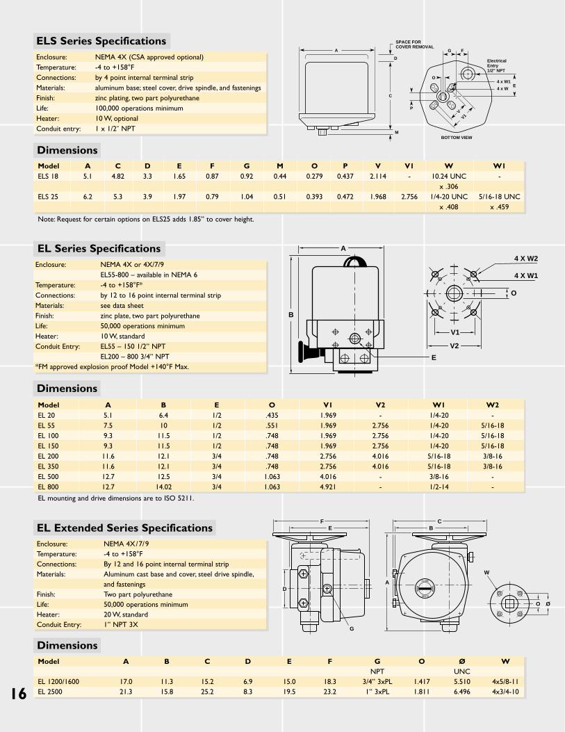
Model A C D E F G M O P V V1 W W1ELS 18 5.1 4.82 3.3 1.65 0.87 0.92 0.44 0.279 0.437 2.114 - 10.24 UNC -
x .306ELS 25 6.2 5.3 3.9 1.97 0.79 1.04 0.51 0.393 0.472 1.968 2.756 1/4-20 UNC 5/16-18 UNC
x .408 x .459
Note: Request for certain options on ELS25 adds 1.85” to cover height.
Model A B E O V1 V2 W1 W2EL 20 5.1 6.4 1/2 .435 1.969 - 1/4-20 -EL 55 7.5 10 1/2 .551 1.969 2.756 1/4-20 5/16-18EL 100 9.3 11.5 1/2 .748 1.969 2.756 1/4-20 5/16-18EL 150 9.3 11.5 1/2 .748 1.969 2.756 1/4-20 5/16-18EL 200 11.6 12.1 3/4 .748 2.756 4.016 5/16-18 3/8-16EL 350 11.6 12.1 3/4 .748 2.756 4.016 5/16-18 3/8-16EL 500 12.7 12.5 3/4 1.063 4.016 - 3/8-16 -EL 800 12.7 14.02 3/4 1.063 4.921 - 1/2-14 -
EL mounting and drive dimensions are to ISO 5211.
Model A B C D E F G O Ø WNPT UNC
EL 1200/1600 17.0 11.3 15.2 6.9 15.0 18.3 3/4” 3xPL 1.417 5.510 4x5/8-11EL 2500 21.3 15.8 25.2 8.3 19.5 23.2 1” 3xPL 1.811 6.496 4x3/4-10
FE
D
G
CB
A CLOSE
OP
EN
OP
EN
CLOSE
A
B
E
4 X W2
BOTTOM VIEW
SPACE FORCOVER REMOVAL
FG
E4 x W1
Electrical Entry1/2" NPT
4 x W
O
P
A
D
C
M
VV1
ELS Series SpecificationsEnclosure: NEMA 4X (CSA approved optional)Temperature: -4 to +158°FConnections: by 4 point internal terminal stripMaterials: aluminum base; steel cover, drive spindle, and fasteningsFinish: zinc plating, two part polyurethaneLife: 100,000 operations minimumHeater: 10 W, optionalConduit entry: 1 x 1/2˝ NPT
EL Series SpecificationsEnclosure: NEMA 4X or 4X/7/9
EL55-800 – available in NEMA 6Temperature: -4 to +158°F*Connections: by 12 to 16 point internal terminal stripMaterials: see data sheet Finish: zinc plate, two part polyurethaneLife: 50,000 operations minimumHeater: 10 W, standardConduit Entry: EL55 – 150 1/2” NPT
EL200 – 800 3/4” NPT*FM approved explosion proof Model +140°F Max.
4 X W2
4 X W1
O
V1
V2
W
O O
EL Extended Series SpecificationsEnclosure: NEMA 4X/7/9Temperature: -4 to +158°FConnections: By 12 and 16 point internal terminal stripMaterials: Aluminum cast base and cover, steel drive spindle,
and fasteningsFinish: Two part polyurethaneLife: 50,000 operations minimumHeater: 20 W, standardConduit Entry: 1” NPT 3X
Dimensions
Dimensions
Dimensions
17
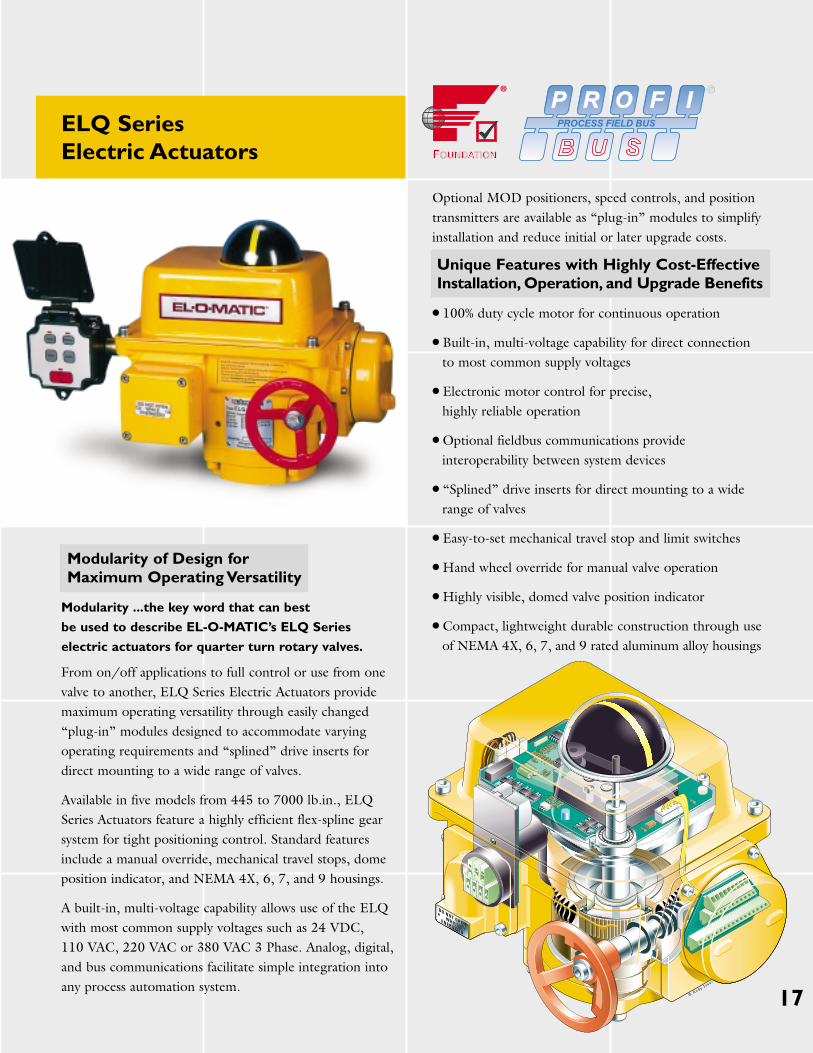
ELQ SeriesElectric Actuators
Modularity of Design for Maximum Operating Versatility
Modularity ...the key word that can best
be used to describe EL-O-MATIC’s ELQ Series
electric actuators for quarter turn rotary valves.
From on/off applications to full control or use from onevalve to another, ELQ Series Electric Actuators providemaximum operating versatility through easily changed“plug-in” modules designed to accommodate varyingoperating requirements and “splined” drive inserts fordirect mounting to a wide range of valves.
Available in five models from 445 to 7000 lb.in., ELQSeries Actuators feature a highly efficient flex-spline gearsystem for tight positioning control. Standard featuresinclude a manual override, mechanical travel stops, domeposition indicator, and NEMA 4X, 6, 7, and 9 housings.
A built-in, multi-voltage capability allows use of the ELQ with most common supply voltages such as 24 VDC, 110 VAC, 220 VAC or 380 VAC 3 Phase. Analog, digital,and bus communications facilitate simple integration intoany process automation system.
Optional MOD positioners, speed controls, and positiontransmitters are available as “plug-in” modules to simplifyinstallation and reduce initial or later upgrade costs.
Unique Features with Highly Cost-Effective Installation, Operation, and Upgrade Benefits
● 100% duty cycle motor for continuous operation
● Built-in, multi-voltage capability for direct connection to most common supply voltages
● Electronic motor control for precise, highly reliable operation
● Optional fieldbus communications provide interoperability between system devices
● “Splined” drive inserts for direct mounting to a wide range of valves
● Easy-to-set mechanical travel stop and limit switches
● Hand wheel override for manual valve operation
● Highly visible, domed valve position indicator
● Compact, lightweight durable construction through useof NEMA 4X, 6, 7, and 9 rated aluminum alloy housings
18
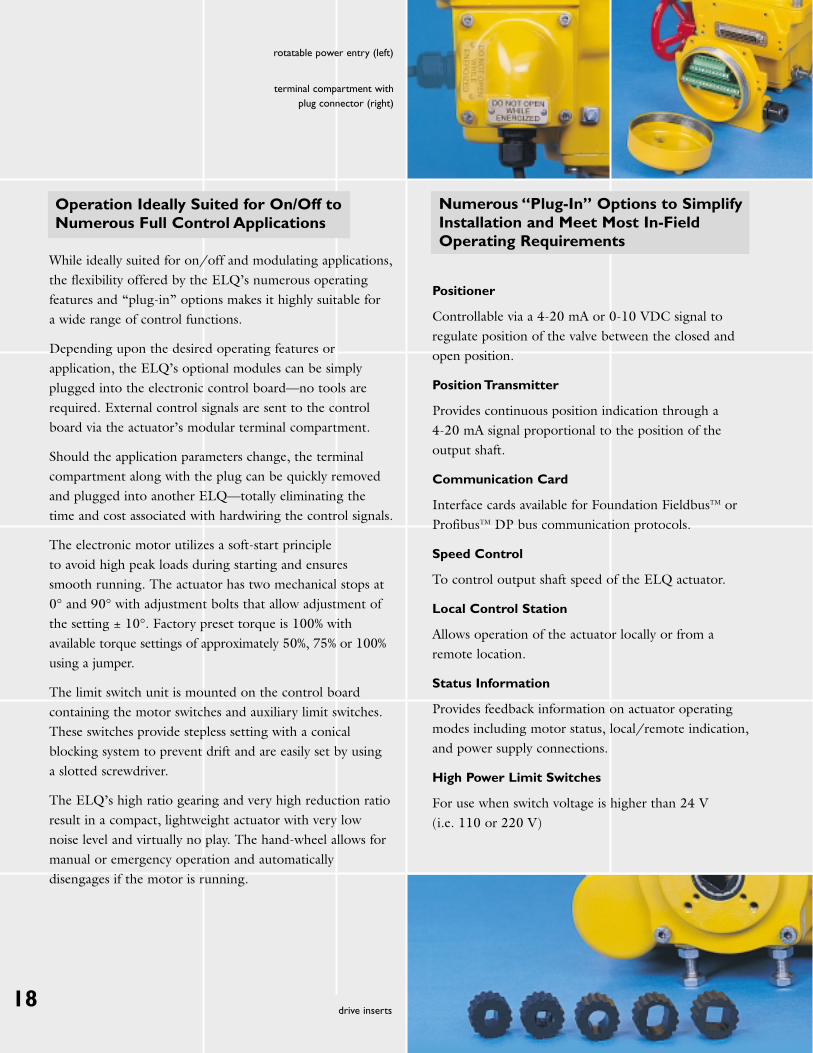
rotatable power entry (left)
terminal compartment withplug connector (right)
drive inserts
Operation Ideally Suited for On/Off to Numerous Full Control Applications
While ideally suited for on/off and modulating applications,the flexibility offered by the ELQ’s numerous operatingfeatures and “plug-in” options makes it highly suitable for a wide range of control functions.
Depending upon the desired operating features orapplication, the ELQ’s optional modules can be simplyplugged into the electronic control board—no tools arerequired. External control signals are sent to the controlboard via the actuator’s modular terminal compartment.
Should the application parameters change, the terminalcompartment along with the plug can be quickly removedand plugged into another ELQ—totally eliminating thetime and cost associated with hardwiring the control signals.
The electronic motor utilizes a soft-start principle to avoid high peak loads during starting and ensuressmooth running. The actuator has two mechanical stops at0° and 90° with adjustment bolts that allow adjustment ofthe setting ± 10°. Factory preset torque is 100% withavailable torque settings of approximately 50%, 75% or 100%using a jumper.
The limit switch unit is mounted on the control boardcontaining the motor switches and auxiliary limit switches.These switches provide stepless setting with a conicalblocking system to prevent drift and are easily set by using a slotted screwdriver.
The ELQ’s high ratio gearing and very high reduction ratioresult in a compact, lightweight actuator with very lownoise level and virtually no play. The hand-wheel allows formanual or emergency operation and automaticallydisengages if the motor is running.
Numerous “Plug-In” Options to Simplify Installation and Meet Most In-Field Operating Requirements
Positioner
Controllable via a 4-20 mA or 0-10 VDC signal toregulate position of the valve between the closed andopen position.
Position Transmitter
Provides continuous position indication through a 4-20 mA signal proportional to the position of theoutput shaft.
Communication Card
Interface cards available for Foundation FieldbusTM orProfibusTM DP bus communication protocols.
Speed Control
To control output shaft speed of the ELQ actuator.
Local Control Station
Allows operation of the actuator locally or from aremote location.
Status Information
Provides feedback information on actuator operatingmodes including motor status, local/remote indication,and power supply connections.
High Power Limit Switches
For use when switch voltage is higher than 24 V (i.e. 110 or 220 V)
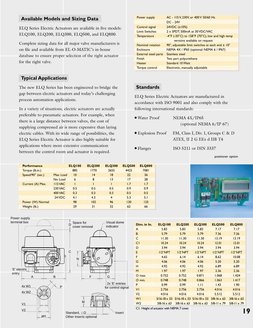
positioner option
Power supply terminal box Space for
cover removalVisual dome indicator
'E' electric entry
Standard,Other inserts optional
2x 'E' entries for control signal
Insert
M
O
V1
V2
øH
P4x W1
4x W2
D
C
A B F G
N
Power supply AC - 115 V, 230V, or 400 V 50/60 Hz
DC - 24V
Control signal 24VDC (±10%)Limit Switches 2 x SPDT, 500mA at 30 VDC/VACTemperature -4°F (-20°C) to 158°F (70°C), low and high temp
versions available on requestNominal rotation 90°, adjustable limit switches at each end ± 10°Enclosure NEMA 4X / IP65 (optional: NEMA 6 / IP67)External steel parts Stainless steelFinish Two part polyurethaneHeater Standard 10 WattTorque control Electronic, manually adjustable
Performance ELQ100 ELQ200 ELQ300 ELQ500 ELQ800Torque (lb.in.) 885 1770 2655 4425 7081Speed/90° (sec.) Max. Load 10 14 18 22 36
No Load 6 8 13 17 28Current (A) Max. 115 VAC 1 1 1 1.7 1.7
230 VAC 0.5 0.5 0.5 0.9 0.9 400 VAC 0.3 0.3 0.3 0.5 0.524 VDC 4.1 4.3 4 5.3 5.1
Power (W) Normal 98 102 96 130 125Weight (lb.) 29 31 32 62 66
Dim. in In. ELQ100 ELQ200 ELQ300 ELQ500 ELQ800A 5.83 5.83 5.83 7.17 7.17B 5.79 5.79 5.79 7.36 7.36C 11.30 11.30 11.30 13.19 13.19C1 10.24 10.24 10.24 12.01 12.01D 3.94 3.94 3.94 3.94 3.94E 1/2˝NPT 1/2˝NPT 1/2˝NPT 1/2˝NPT 1/2˝NPTF 4.65 6.14 6.14 8.62 10.08G 4.06 4.06 4.06 5.20 5.20H 4.92 4.92 4.92 6.89 6.89M 1.97 1.97 1.97 2.36 2.36O max. 0.752 0.752 0.871 1.068 1.424O min. 0.748 0.748 0.866 1.063 1.417P 0.99 0.99 1.11 1.43 1.90V1 2.756 2.756 2.756 4.016 4.016V2 4.016 4.016 4.016 5.512 5.512W1 5/16-18 x .53 5/16-18 x .53 5/16-18 x .53 3/8-16 x .63 3/8-16 x .63W2 3/8-16 x .63 3/8-16 x .63 3/8-16 x .63 5/8-11 x .79 5/8-11 x .79
C1: Height of actuator with NEMA 7 cover. 19
Standards
ELQ Series Electric Actuators are manufactured in accordance with ISO 9001 and also comply with thefollowing international standards:
● Water Proof NEMA 4X/IP65(optional NEMA 6/IP 67)
● Explosion Proof FM, Class I, Div. 1, Groups C & DATEX, II 2 G EEx d IIB T4
● Flanges ISO 5211 or DIN 3337
Available Models and Sizing Data
ELQ Series Electric Actuators are available in five models:ELQ100, ELQ200, ELQ300, ELQ500, and ELQ800.
Complete sizing data for all major valve manufacturers ison file and available from EL-O-MATIC’s in-housedatabase to ensure proper selection of the right actuatorfor the right valve.
Typical Applications
The new ELQ Series has been engineered to bridge thegap between electric actuators and today’s challengingprocess automation applications.
In a variety of situations, electric actuators are actuallypreferable to pneumatic actuators. For example, whenthere is a large distance between valves, the cost ofsupplying compressed air is more expensive than layingelectric cables. With its wide range of possibilities, theELQ Series Electric Actuator is also highly suitable forapplications where more extensive communicationbetween the control room and actuator is required.

NORTH & SOUTH AMERICAEmerson Process Management,Valve Automation division9009 King Palm DriveTampaFlorida33619United States of America T +1 813 630 2255F +1 813 630 [email protected]
SOUTH AFRICAEmerson Process Management,Valve Automation divisionP.O. Box 979Isando16002 Monteer RoadIsandoSouth AfricaT +27 11 974 3336F +27 11 974 [email protected]
SINGAPOREEmerson Process Management,Valve Automation division9 Gul Road #01-02 Singapore 629361T +65 6501 4600 F +65 6268 [email protected]
EUROPE MIDDLE EAST & AFRICAEmerson Process Management,Valve Automation divisionP.O. Box 2237550 AE Hengelo (O)Asveldweg 117556 BT Hengelo (O)The NetherlandsT +31 74 256 10 10F +31 74 291 09 [email protected]
GERMANYEmerson Process Management,Valve Automation divisionPostfach 500155D-47870 WillichSiemensring 112D-47877 WillichGermanyT +49 2154 499 660F +49 2154 499 [email protected]
Important: Due to Emerson’s continuing commitment to engineeredproduct advancement, data presented herein is subject to change.
EL-O-MATIC® is a registered trademark of EL-O-MATIC International.PosiFlex™ is a trademark of EL-O-MATIC International.PROFIBUS™ is a registered trademark of PROFIBUS International. Foundation Fieldbus® is a registered trademark of Fieldbus Foundation.
Bulletin # 101.00 Rev: 3-06
© 2001 Emerson. All rights reserved. 2.5M/3-06
Please visit www.El-O-Matic.comfor the latest product information.