pneumatic diaphragm actuator (pda) gate valve … · usa api 6a diaphragm pneumatic gate valve. we...
TRANSCRIPT

[email protected] BOOKLET OF VALVEWORKS USA. DO NOT REPRODUCE WITHOUT EXPLICIT PERMISSION.
Page 1 [email protected]
PNEUMATIC DIAPHRAGM ACTUATOR (PDA)GATE VALVE SERVICE AND OPERATION MANUAL
PROPRIETARY BOOKLET OF VALVEWORKS USA. DO NOT REPRODUCE WITHOUT EXPLICIT PERMISSION.

[email protected] BOOKLET OF VALVEWORKS USA. DO NOT REPRODUCE WITHOUT EXPLICIT PERMISSION.
Page 2
PDA SERVICE AND OPERATION MANUAL
INTRODUCTIONIn appreciation to our customer for purchasing our product, we have prepared this OperationManual to assist you in the Operation, Maintenance, Assembly and Installation of the ValveworksUSA API 6A Diaphragm Pneumatic Gate Valve. We encourage following the recommendations in this booklet to attain the best possible service from our product, which is designed and proven to offer the service one can expect of a quality product.To contact a representative for more specific information pertaining to a special problem:
1650 SWAN LAKE ROADBOSSIER CITY, LA USA 71111
PHONE 318-425-0266FAX 318-425-0934TOLL FREE 888-425-0266EMAIL [email protected] WWW.VALVEWORKSUSA.COM
QUALITYValveworks USA management and employees are committed to continually improve the effectiveness of our quality management system to produce a quality assured product which meets or exceeds our customer’s expectations and requirements.
SAFETYCaution must be taken as to the surrounding area and its potential dangers of projectiles.Pressure kills! Even a loose, stand alone valve may contain trapped pressure which will turn any component into a projectile missile when disassembled, causing injury or death. Never stand over a component or in its path of release during assembly. Always operate the valves from the open to close position slowly releasing trapped pressure. Always remove fittings first, taking extreme caution to their potential danger as a projectile. If the valve is frozen and can not be operated, take extreme caution to the disassembly of the components. Weighted blankets or protective screens and shields should be utilized. Caution should be taken when handling components during disassembly and assembly, as most components are heavy, greasy, hard to handle and have edges which can cause injury. Always be cautious of how the valve is positioned and standing. Be sure the valve is secured in position so there is no possible chance of tipping over. Never apply test pressure above the manufacturers rated working pressure. The shell test pressure above the working pressure has already been tested by the manufacturer and is not required after the initial assembly test of the valve. The manufacturer has already verified the quality of the valve shell body components and will void the warranty from the manufacturer if the valve is pressure tested above the rated working pressure indicated for the valve. Always wear steel toes shoes, hard hat, eye and ear protection while performing repairs.

[email protected] BOOKLET OF VALVEWORKS USA. DO NOT REPRODUCE WITHOUT EXPLICIT PERMISSION.
Page 3
TABLE OF CONTENTSAPPLICATIONS 4TEMPERATURE RATING 4TRIM CHART 4ORDERING INFORMATION 5ACTUATOR ASSEMBLY INSTRUCTIONS 6ACTUATOR ASSEMBLY-BOM 7-9BONNET ASSEMBLY INSTRUCTIONS 10BONNET ASSEMBLY-BOM 10BONNET TO VALVE ASSEMBLY INSTRUCTIONS 11BONNET TO VALVE ASSEMBLY-BOM 12PERIODIC MAINTENANCE 12OPERATION 13OPENING AND CLOSING THE VALVE 13TROUBLESHOOTING 14APPENDIX 15-18LIMITED PRODUCT WARRANTY 19-20ORDERS POLICY 20PHYSICAL DMENSIONS 21
PDA SERVICE AND OPERATION MANUAL

[email protected] BOOKLET OF VALVEWORKS USA. DO NOT REPRODUCE WITHOUT EXPLICIT PERMISSION.
Page 4
APPLICATIONSValveworks USA Diaphragm Pneumatic gate valves can be applied to the following sizes and working pressures.
APPLICATION OPTIONS AVAILABLEGATE VALVE SIZE 1-13/16 through 7-1/16MAXIMUM ALLOWABLE WORKING PRESSURE (MAWP) 0 to 20MACTUATOR MAXIMUM OPERATING PRESSURE 170 PSITEMPERATURE RANGE -46°C TO 121°C
(-50°F TO 250°F)
The Diaphragm Pneumatic Gate Valves covered in this manual are suitable for performance requirement levels 1 and 2, PR1 and PR2 respectively.TEMPERATURE RATING
TEMPERATURECLASSIFICATION
OPERATING RANGE°C (°F)
K -60 82 -75 180L -46 82 -50 180N -46 60 -50 140P -29 82 -20 180S -18 60 0 140T -18 82 0 180U -18 121 0 250V 2 121 35 250
TRIM CHARTMATERIAL
CLASSMINIMUM MATERIAL REQUIREMENTS
BODY, BONNET, END AND OUTLETCONNECTIONS
PRESSURE-CONTROLLING PARTS, STEMS, AND MANDREL HANGERS
AA - General Service Carbon or low-alloy steel Carbon or low-alloy steelBB - General Service Carbon or low-alloy steel Stainless steelCC - General Service Stainless steel Stainless steelDD - Sour Service a Carbon or low-alloy steel b Carbon or low-alloy steel b
EE - Sour Service a Carbon or low-alloy steel b Stainless steel b
FF - Sour Service a Stainless steel b Stainless steel b
HH - Sour Service a CRAs b CRAs b
a As defined by NACE MR0175.b In compliance with NACE MR0175.
As shown by API-6A. For specific details consult Valveworks USA.
PDA SERVICE AND OPERATION MANUAL

[email protected] BOOKLET OF VALVEWORKS USA. DO NOT REPRODUCE WITHOUT EXPLICIT PERMISSION.
Page 5
ORDERING INFORMATIONThe following information should be provided with any request for quote or order placement of Valveworks USA Diaphragm Pneumatic Gate Valves: DIAPHRAGM• Model, Series and Size of Diaphragm• API 6A Requirements (PR – PSL)• ISO Certification Requirements• Well Fluid Pressure• Temperature• Location (Onshore/Offshore)• Material Class• Actuator Control Pressure Availability• Special Test Requirements• Special Material Requirements
VALVE• Model and Size of Valve• Pressure Rating (maximum)• API 6A Requirements (PR-PSL)• Temperature Rating (API 6A)• Material (API 6A)• Any Special Test Requirements• Any Special Material Requirements• Any Special Coating or Protection Requirements• Other Specifications and/or Certifications
ACTUATOR ACCESSORIES (MECHANICAL)Safety Lock Open Device:This device is used to mechanically stroke the actuator. It is used on small or low-pressure valves while valve body is pressurized. It is typically used during installation and testing phases of well completions.
Fusible Lock Open Cap:Mechanically holds open the actuator and valve during work over or when the safety systems are inoperative. This device locks the actuator in the down position, allowing it to rise only in the event of a fire.
PDA SERVICE AND OPERATION MANUAL

[email protected] BOOKLET OF VALVEWORKS USA. DO NOT REPRODUCE WITHOUT EXPLICIT PERMISSION.
Page 6
PDA SERVICE AND OPERATION MANUAL
ASSEMBLY INSTRUCTIONSThe following steps have to be followed before assembly of any component of the PDA series equipped valves.
• Assembly work area must be clean and free of dirt, metallic shavings and wood particles.• Surface preparation of work area should be metallic or covered with a layer of corrugated cardboard.• All lubricants and utensils used in assembly must be clean.• All tools used in assembly must be clean and in good working order.• Clean all components (metallic) prior to assembly.• Keep all elastomers and plastic base materials in bags or boxes until needed for assembly.• Inspect all components for burrs, dings, marks, scrapes, nicks, and etc. prior to assembly.
PNEUMATIC DIAPHRAGM ACTUATOR• Place the O-ring in the o-ring groove at the base of the Top Shaft.• Lay the Diaphragm over the domed side of the Diaphragm Plate and align the center holes.• Screw the top shaft into the diaphragm plate while ensuring that the o-ring stays in the groove. Tighten
with the open-end wrench.• Tilt the top Shaft and diaphragm Plate 90° to gain access to the bottom of the diaphragm plate. Do not pinch
the diaphragm under the diaphragm plate.• Place the Lock Washer on the Cap Screw. Insert the screw through the diaphragm plate and screw it into
the top shaft. Tighten the cap screw with the hex key wrench while bracing the top shaft with the open-end wrench.
• This sub-assembly should rest on the bottom of the diaphragm plate.• Install the Rod Wiper into the groove inside the Seal Retainer with the inside edge of the rod• wiper pointing in the direction of the smaller diameter portion (top) of the seal retainer.• Install the O-Ring in the ring groove located inside of the seal retainer.• Install the two O-Rings in the ring grooves located on the outside of the seal retainer.• Insert the Seal Retainer Assembly into the top plug of the Upper Diaphragm Case with the smaller diameter
portion facing up. Press the seal retainer into the top plug of the upper diaphragm case so that the ring-groove in the top plug is fully exposed.
• Install the Retainer Ring in the ring-groove in the top plug to hold the seal retainer in place.• With the upper diaphragm case turned upside-down, install the Wear Bearing in the wear bearing pocket
located just inside the bottom of the top plug of the upper diaphragm plate.• With the Diaphragm Assembly resting on the bottom of the diaphragm plate, lower the upper diaphragm case
onto the diaphragm with the top shaft protruding through the top plug of the upper diaphragm case.• This sub-assembly should rest on the bottom of the diaphragm plate until used for Main Assembly.• Place the Lower Diaphragm Case on the lower ring with breather holes aligned with valve body flanges.
Install and tighten the 8 Hex. Bolts that fasten the lower diaphragm plate to the lower ring.• Place the Upper Diaphragm Case Assembly on the lower diaphragm case assembly with bolt holes aligned.
Insert 24 Hex. Bolts into the bolt holes and install 24 Lock Washers and 24 Hex. Nuts and tighten• using star pattern as described in WI-0014 using the pneumatic ratchet wrench on an air hose• regulated to produce 70 lbf-ft of torque on the hex. nuts.• Install 4 Breathers in threaded breather holes.• After the actuator has been pressure tested, install Burst Disc Fitting in the pressure nipple located on the
same side of the assembly as the body grease fittings.

[email protected] BOOKLET OF VALVEWORKS USA. DO NOT REPRODUCE WITHOUT EXPLICIT PERMISSION.
Page 7
Diaphragm Pneumatic Actuator
PDA SERVICE AND OPERATION MANUAL

[email protected] BOOKLET OF VALVEWORKS USA. DO NOT REPRODUCE WITHOUT EXPLICIT PERMISSION.
Page 8
PDA SERVICE AND OPERATION MANUAL
Diaphragm Pneumatic Actuator

[email protected] BOOKLET OF VALVEWORKS USA. DO NOT REPRODUCE WITHOUT EXPLICIT PERMISSION.
Page 9
Diaphragm Pneumatic Actuator - BILL OF MATERIALSITEM DESCRIPTION QTY
1 DIAPHRAGM 12 DIAPHRAGM PLATE 13 ANTI-ROTATE SLIP 14 SEAL RETAINER 15 LOWER RING 16 SEAL RETAINER SHAFT 17 BOLT, HEX HD 18 LOCK OPEN CAP 19 SPRING 1
10 UPPER DIAPHRAGM CASE - WELDMENT 111 LOWER DIAPHRAGM CASE - WELDMENT 112 WEAR BEARING 113 ROD WIPER 114 RETAINER RING 115 BREATHER 416 CAP SCREW 117 WASHER, LOCK STANDARD 118 BOLT, HEX HD 919 BOLT, HEX HD 2420 WASHER, LOCK STANDARD 2421 NUT, HEX HD 2422 BURSC DISC 123 SHIM 224 PACKING RETAINER 126 SPRING PLATE 127 WEAR BEARING 128 POLYPAK SEAL 129 SET SCREW 139 O-RING 140 O-RING 141 O-RING 142 O-RING 246 O-RING 1
PDA SERVICE AND OPERATION MANUAL

[email protected] BOOKLET OF VALVEWORKS USA. DO NOT REPRODUCE WITHOUT EXPLICIT PERMISSION.
Page 10
PDA SERVICE AND OPERATION MANUAL
BONNET ASSEMBLY - BILL OF MATERIALSITEM DESCRIPTION QTY
27 SHIMS 428 PACKING RETAINER 129 STEM, BONNET 131 BONNET 132 WEAR BEARING 133 POLYPAK SEAL 334 O- RING 135 O- RING 139 STUD 840 HEX NUT 8
BONNET ASSEMBLY INSTRUCTIONS• Install the Body Grease Fitting in the side of the bonnet flange. (Model FC bonnets only)• Place Bonnet on flat surface and insert Stem Packing with the bead (pressure-side) facing down toward the
bonnet flange.• Insert Wear Bearing into Packing Retainer using channel-lock pliers to compress the wear bearing.• Install Inner O-Ring in ring groove located inside the packing retainer.• Install Outer O-Ring in the packing retainers outside ring groove that has no holes in it.• Screw Packing Retainer Assembly into the bonnet and tighten with a large pipe wrench using the upper (non-
threaded) portion of the packing retainer.

[email protected] BOOKLET OF VALVEWORKS USA. DO NOT REPRODUCE WITHOUT EXPLICIT PERMISSION.
Page 11
BONNET TO VALVE ASSEMBLY INSTRUCTIONS• Insert the Operating Stem into the bottom of the bonnet and lower the bonnet onto the Valve Body Assembly.
Install bonnet nuts and tighten using star pattern.• Screw the Lower Ring onto the bonnet and tighten.• Screw the Anti-Rotate Slip onto the packing retainer and tighten.• Screw Set Screw into the threaded hole at the top of the anti-rotate slip. The set screw should be tightened
firmly against the upper (non-threaded) portion of the packing retainer.• Move the gate into the open position and verify with the drift rod. Hold the Spring Plate in position on top
of the operating stem and slide a stack of shims into the space between the top of the packing retainer and the bottom of the spring plate to determine the correct number of shims to use for setting the drift. Remove spring plate and slide shims onto operating stem so that they rest on the packing retainer. Replace the spring plate to ensure that no space exist between the shims and the bottom of the spring plate.
• Place the spring on the lower ring. Place the spring plate on the top of the spring and insert the spring plate bolt through the spring plate. Screw the spring plate bolt into the top of the operating stem as far as possible by hand. Using a wrench, compress the spring by screwing the spring plate bolt into the operating stem until it is tight.
• The bonnet assembly is now ready to accept a Valveworks pneumatic diaphragm actuator.
PDA SERVICE AND OPERATION MANUAL

[email protected] BOOKLET OF VALVEWORKS USA. DO NOT REPRODUCE WITHOUT EXPLICIT PERMISSION.
Page 12
PDA SERVICE AND OPERATION MANUAL
BONNET TO VALVE - BILL OF MATERIALSITEM DESCRIPTION QTY
27 SHIM 428 PACKING RETAINER 129 STEM, BONNET 131 BONNET 132 WEAR BEARING 133 POLYPAK SEAL 334 O- RING 138 BODY GREASE FITTING 239 BODY, FLANGED 140 GATE 141 LIFT NUT 142 SEAT 243 GATE GUIDE 244 HEX NUT 845 STUD 846 BONNET SEAL RING 1
47 BONNET 1
PERIODIC MAINTENANCEValveworks USA recommends the following maintenance schedule.
Interval Maintenance OperationOnce a Month Cycle open and close one time.As Required Clean debris from vent and breather holes. Replace
as needed.Every 250 cycles Replace diaphragm, seals and wear rings.When seals are Replaced Inspect top shaft and operating stem.As Required Keep valve body cavity filled with grease at all times.As Required Tighten the nuts on the actuator housing to minimize
leaks
These are just recommended intervals of maintenance. Depending on the level of usage, your valve(s) may require more or less maintenance than this manual suggests. For more information, contact Valveworks USA.

[email protected] BOOKLET OF VALVEWORKS USA. DO NOT REPRODUCE WITHOUT EXPLICIT PERMISSION.
Page 13
PDA SERVICE AND OPERATION MANUAL
OPERATIONThe Safety Valve with a Valveworks USA actuator is normally supplied in the fail-closed operating configuration. Pneumatic actuator supply drives the valve’s reverse ported gate down and holds it in open position under normal operating conditions. In the event of an abnormal condition, the actuator supply pressure is released or bled off by quick exhaust mechanisms, allowing the valve to close by body pressure acting on the bonnet stem diameter and spring force. Restoration of pneumatic actuator supply pressure automatically reopens the valve.
When required, the valve can be configured with a fail open gate design for a blow-down system.
OPENING AND CLOSING THE VALVEThe actuator input pressure drives the reverse ported gate downwards into open position as shown in the figure. The arrow shows the pressure input location.
As the actuator pressure exits from the diaphragm, valve body pressure and actuator spring force close the valve as shown in the figure. The arrow shows the pressure exit location.

[email protected] BOOKLET OF VALVEWORKS USA. DO NOT REPRODUCE WITHOUT EXPLICIT PERMISSION.
Page 14
TROUBLESHOOTINGPROBLEM CAUSE SOLUTION
LEAKAGE WHEN CLOSED
Seats Disconnect from service and replace the seats.
LEAKAGE WHEN OPEN THRU BODY/BONNET
CONNECTION
Bonnet Seal Ring Disconnect from service and replace the bonnet seal ring.
LEAKAGE WHEN PARTIALLY OPEN THRU
TOP OF BONNET
Packing Disconnect from service and replace the packing.
LEAKAGE AT FLANGE Flange Seal Ring Disconnect from service and replace the flange seal ring.
CONTROL PRESSURE WILL NOT BUILD IN
ACTUATOR
Damaged control line Inspect control line for damage and/or leaking fittings.Insufficient pressure in
control lineInstall gauge at pressure source to verify desired pressure available.
Perforated Diaphragm Replace diaphragm.Leaking around bolted
flangeTighten flange bolts. If problem persists, replace diaphragm.
Leaking through top plug of actuator
Replace top shaft seal.
ACTUATOR WILL NOT STROKE ON A
VALVE WHETHER OR NOT VALVE
IS PRESSURIZED
Insufficient pressure in control line
Check pressure from source. Consult control pressure information from the information chart per size valve application (appendix).
Bonnet to bonnet stem binding
Consult appropriate maintenance and operating instructions for bonnet.
Valve and/or seals improperly installed
Remove actuator and bonnet. Repair and/or replace faulty valve components.
Debris in actuator and/or valve body
Remove actuator and inspect for large pieces of debris or build-up of small debris. If no interference is found, remove bonnet and inspect
valve cavity. Remove any debris found.
LEAKAGE WHEN CLOSED
Excessive friction due to loss of lubrication in
bonnet/valve.
Lubricate valve in accordance with maintenance instructions.
Gate and seats are improperly installed causing excessive
friction.
Remove actuator per instructions in this manual. Manually push and/or pull bonnet stem to determine severity of binding. If severe, clean
and inspect gate and seats for wear/abrasion. Replace if signs of galling are observed.
Valve has frozen liquid in valve body
Steam the valve from outside such that the frozen liquid inside melts.
Trapped pressure on the diaphragm
Remove the burst disc from the actuator to bleed the trapped pressure.
Restriction of movement of top shaft
Remove manual override or top cap such that the top cap is visible.
VALVE BORE WILL NOT DRIFT AFTER
ASSEMBLY OF BONNET TO VALVE
Wrong number of shims installed.
Remove actuator per instructions. Check number of spacers.
Improper gate to stem engagement.
Remove actuator and bonnet as per instruction manual. Adjust engagement per valve in manufacturer’s instructions and/or drawings.
ACTUATOR LOWER RING TRIES TO
UNSCREW
Anti-Rotate Slip is not torqued.
Remove Pot assembly, Spring, Spring plate and re-torque with pipe wrench as per torque specifications.
PDA SERVICE AND OPERATION MANUAL

[email protected] BOOKLET OF VALVEWORKS USA. DO NOT REPRODUCE WITHOUT EXPLICIT PERMISSION.
Page 15
PDA SERVICE AND OPERATION MANUAL
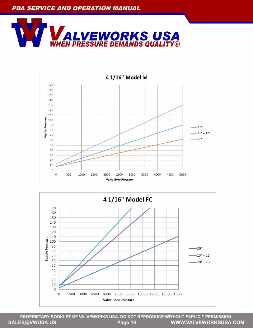
APPENDIXThe plots shown below are close approximations and can vary on a case by case. Please contact Valveworks USA for more information.

[email protected] BOOKLET OF VALVEWORKS USA. DO NOT REPRODUCE WITHOUT EXPLICIT PERMISSION.
Page 16
PDA SERVICE AND OPERATION MANUAL

[email protected] BOOKLET OF VALVEWORKS USA. DO NOT REPRODUCE WITHOUT EXPLICIT PERMISSION.
Page 17
PDA SERVICE AND OPERATION MANUAL
[email protected] BOOKLET OF VALVEWORKS USA. DO NOT REPRODUCE WITHOUT EXPLICIT PERMISSION.
Page 18
PDA SERVICE AND OPERATION MANUAL

[email protected] BOOKLET OF VALVEWORKS USA. DO NOT REPRODUCE WITHOUT EXPLICIT PERMISSION.
Page 19
PDA SERVICE AND OPERATION MANUAL
Limited Product WarrantyThe following limited warranty (“Limited Warranty”) is exclusive and shall supersede all other warranties, whether express, implied or statutory, including, but not by way of limitation, any warranty of merchantability of fitness for any particular purpose. All other warranties or liabilities, expressed or implied, oral or statutory, including any warranty of merchantability or fitness for a particular purpose are hereby terminated and waived upon Purchaser purchasing any Products (as that term is defined herein) manufactured by VALVEWORKS USA.
VALVEWORKS USA hereby warrants to each original purchaser (“Purchaser”) of material(s) or product(s) (hereinafter collectively referred to as “Products” or “Product(s)”) manufactured by VALVEWORKS USA that such products are free from material and workmanship defects when operated under Normal Use (as defined herein) and Normal Service (as defined herein) for a period of one (1) year from the date of shipment (“Warranty Period”). This warranty is valid only for the original purchaser of the material(s) or product(s), and is non-transferrable. “Normal Use” shall mean the intended use of the product for which it was designed by VALVEWORKS USA. “Normal Service” shall mean the necessary servicing as suggested or required by VALVEWORKS USA, industry standards, or applicable laws and regulations.
THIS WARRANTY WILL BE NULL AND VOID FOR THE FOLLOWING PRODUCTS:
• Other than testing during testing processes by VALVEWORKS USA in accordance with industry rules and regulations, any Product(s) that has been tested to, or subjected to, any pressure greater than the stated product working pressure* at any time, other than by VALVEWORKS USA during testing processes per industry rules and regulations. PRODUCTS SHOULD NEVER BE TESTED / SUBJECTED TO PRESSURE GREATER THAN THE STATED PRODUCT WORKING PRESSURE*. THIS IMMEDIATELY VOIDS THIS LIMITED WARRANTY, AND IS AN EXTREMELY DANGEROUS SAFETY RISK. • Any product repaired, altered, or modified by any contractor, laborer, person or entity that has not been authorized in writing by VALVEWORKS USA. • Any product, in VALVEWORKS USA’s reasonable judgment, that has been subject to negligence, accident, improper storage, or improper handling by any person(s). • Any product which has not been operated or maintained in accordance with normal practices and in conformity with the manufacturer’s recommendations, industry standards, and operation and maintenance specifications of VALVEWORKS USA. *Stated Product Working Pressure is defined as “the maximum internal pressure that the equipment is designed to contain and / or control”
Under any circumstances where this Limited Warranty is voided on any Product(s) manufactured and supplied by VALVEWORKS USA, VALVEWORKS USA is immediately excluded from any and all liabilities associated with such Product(s).
For gate valves used in extreme service conditions such as “frac” applications, VALVEWORKS USA recommends full lubrication of the gate valve body cavity and bonnet assemblies between each frac stage (or zone). Failure to comply with this recommendation COULD result in warranty claims being denied. Custom orders, or orders where modifications are made to VALVEWORKS USA products by VALVEWORKS USA per the purchaser’s request to the purchaser’s design criteria, and do not conform to VALVEWORKS USA design criteria, are subject to review at the time of contract review to determine whether warranty coverage applies to that particular order. Unless specified otherwise in writing at the time of order placement, warranty coverage will NOT apply to the aforementioned type(s) of order(s).

[email protected] BOOKLET OF VALVEWORKS USA. DO NOT REPRODUCE WITHOUT EXPLICIT PERMISSION.
Page 20
VALVEWORKS USA obligations under this Limited Warranty consist of, and shall be expressly limited to, reasonable efforts to repair, replace or, at VALVEWORKS USA’S sole option, refund the purchase price. The cost of labor for installing a Product that has been repaired or replaced shall be borne by Purchaser. Replacement parts provided under the terms of this Limited Warranty are covered by this Limited Warranty for the remainder of the Warranty Period, and no obligations fulfilled under the terms and conditions of this Limited Warranty shall ever extend the Warranty Period. Limited Warranty services provided hereunder shall not give rise to any kind of liability that may be caused by the delays in VALVEWORKS USA performing its obligations under this Limited Warranty.
The remedy for claims against VALVEWORKS USA for any breach of this Limited Warranty shall be limited to the replacement of any product that was proven defective in material or workmanship. Such remedy shall only be available upon written notice to VALVEWORKS USA of such defect within thirty (30) days of delivery of the Product(s), and the return of such Product(s) to VALVEWORKS USA at the address provided herein for written notice. Costs of labor, freight, drayage, or other similar charges shall be at the expense of the customer.
Please contact VALVEWORKS USA at 1-318-425-0266 prior to returning any Product(s) covered by this Limited Warranty. Upon determination that a Limited Warranty claim is valid, VALVEWORKS USA shall issue a return authorization number. HOWEVER, THE DELIVERY OF AN ALLEGEDLY DEFECTIVE PRODUCT NOT BEARING A VALID RETURN AUTHORIZATION NUMBER WILL BE REFUSED, AND THE SHIPMENT WILL BE RETURNED TO THE SENDER AT THE SENDER’S EXPENSE. Except as specifically provided herein, any Purchaser hereby waives the right to seek claims, damages or other legal or equitable remedies against or from VALVEWORKS USA, its principals, subcontractors, agents, vendors, suppliers and/or design professionals under any and all causes of action whether statutory, at common law or at equity, including but not limited to any claims based on implied warranties of fitness, redhibition, reduction of the purchase price, negligence and/or strict liability. The agreements and remedies contained in this Limited Warranty are the sole remedies available to any Purchaser as to the issues raised herein, shall be enforceable to the fullest extent permissible by applicable state and federal law, and shall apply to any claim thereafter made against VALVEWORKS USA or any other person related to any VALVEWORKS USA Products. Purchaser’s sole remedy is as prescribed in the terms and conditions of this Limited Warranty document. In no event shall VALVEWORKS USA, its agent(s), or employees be liable for any injuries or damages to any person or property whatsoever, or for any special, indirect, secondary, or consequential damage of any nature however arising. By Purchaser purchasing any Products from VALVEWORKS USA, Purchaser agrees (without any further action required by VALVEWORKS USA or Purchaser) to all remedies, waivers and limitations of warranty set forth herein.
Written Notice: Any written notice shall be sent to 1650 Swan Lake Road, Bossier City, Louisiana 71111.
The obligations of VALVEWORKS USA under this Limited Warranty are limited by the terms and conditions provided herein.
This warranty is limited in extent to the warranty, if any, which the user receives from the manufacturer(s) of any component part(s) or buyout items for resell. All other warranties or liabilities, expressed or implied, oral or statutory, including any warranty of merchantability or fitness for a particular purpose are expressly denied. In no event shall VALVEWORKS USA, its agent(s), or employees be liable for injury or damage to any person or property whatsoever or for any special, indirect, secondary, or consequential damage of any nature however arising.
ORDERS POLICY
All orders for Product(s) are subject to acceptance by VALVEWORKS USA, and such acceptance shall not be unreasonably withheld. Prices are subject to change without notice and any errors in published or quoted prices are subject to correction. No Product(s) may be returned for credit without written authorization from VALVEWORKS USA. Credit will not be issued for Product(s) after the Warranty Period. VALVEWORKS USA reserves the right to deduct reconditioning and handling charges when issuing credit for returned material(s) or product(s). Products of special design, not considered “standard” to the VALVEWORKS USA product line, will not be permitted to be returned.
PDA SERVICE AND OPERATION MANUAL

[email protected] BOOKLET OF VALVEWORKS USA. DO NOT REPRODUCE WITHOUT EXPLICIT PERMISSION.
Page 21
PDA SERVICE AND OPERATION MANUAL
SERIES A B C D E F G10” 16.166 13.533 4.759 11.281 1.247 6.170 12.87512” 18.143 15.284 3.612 13.038 1.247 7.495 15.15015” 20.666 16.774 3.463 14.511 1.247 7.825 18.39518” 26.048 20.868 6.470 18.666 1.247 9.600 21.13020” 25.865 22.031 6.171 19.826 1.247 9.760 23.500
ALL DIMENSIONS ARE IN INCHES
PHYSICAL DIMENSIONS

[email protected] BOOKLET OF VALVEWORKS USA. DO NOT REPRODUCE WITHOUT EXPLICIT PERMISSION.
Page 22 [email protected] BOOKLET OF VALVEWORKS USA. DO NOT REPRODUCE WITHOUT EXPLICIT PERMISSION.
1650 SWAN LAKE ROADBOSSIER CITY, LA USA 71111
PHONE 318-425-0266FAX 318-425-0934TOLL FREE 888-425-0266EMAIL [email protected] WWW.VALVEWORKSUSA.COM