pneumatic delivery of samples of iron, steel, and slag to the chemical laboratory
TRANSCRIPT
P N E U M A T I C DELIVERY OF S A M P L E S OF I R O N , S T E E L ,
A N D S L A G T O T H E C H E M I C A L L A B O R A T O R Y
(UDC 669.1.621.547)
A, I . D o r m a n , L. Z . L e s h c h i n s k i i , V . S. K l y a s h k o , A . S. B a k s h i n o v , a n d A . N, L u k a s h o v a
Magnitogorsk Meta l lu rg ica l Combine Translated from Metallurg, No. 10,
pp. 12-13, October, 1964
Contemporary requirements for conduct ingblast - furnace and open-hear th smelt ing have led to the necessity
of making a large number of chemica l analyses of samples of iron, steel, and slag. Thus, in the blas t - furnace mi l l
of our combine up to 100 samples of iron and slag are taken every day, and a great dea l of t ime is wasted in
del iver ing them to the chemica l laboratory. When the length of the modern blast- furnace mi l I is up to 1 O00 m and the
c h e m i c a l laboratory is located in the center of the mil l , the distance from the outermost furnaces to the laboratory is up to 500 rn and del ivery of a single sample takes 8-10 rain. For delivery of 100 samples 30 man-hours are required daily, in the open-hear th mi l l st i l l more working t ime is wasted in del ivering samples.
The technologica l bureau of the blas t - furnace mi t l worked out a scheme for mechaniz ing the del ivery of samples of iron and slag from the cast ing bays of the b ias t - fumaces to the c h e m i c a l laboratory by means of com-
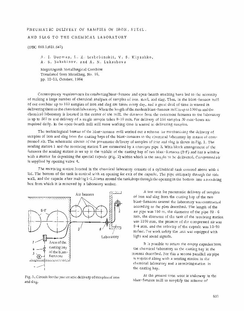
pressed air. The schemat ic circuit of the pneumat ic del ivery of samples of iron and slag is shown in Fig. 1. The
sending station 1 and the rece iv ing station 2 are connected by a conveyer pipe 3. With block arrangement of the
furnaces the sending station is set up in the middle of the casting bay of two blast.- furnaces (B-F) and has a window
with a shutter for depositing the specia l capsule (Fig. 2) within which is the sample to be del ivered, Compressed air is supplied by opening va lve 4.
The receiv ing station loca ted in the chemica l laboratory consists of a cyl indr ica l tank covered above with a l id . The bottom of the tank is conical with an opening for exit of the capsule. The pipe obtiqueIy through the side wall, and the capsule after making 1-1.5 turns around the tank, drops through the opening in the bottom into a receiving box from which it is removed by a laboratory worker.
Air heaters 7;',, '/: 7
B-F
Laborato y
~ casting bay 1 ,5 , T of the blast- ,]
I
Fig. 1, Circuit for the pneumat ic del ivery o f samples of iron and slag.
A test unit for pneumat ic del ivery of samples of iron and slag from the casting bay of the two blast-furnaces nearest the laboratory was constructed
according to the plan described. The length of the air pipe was 180 m, the d iameter of the pipe 89 . 6
ram, the d iameter of the tank of the receiv ing station was t100 ram, the pressure of the compressed an'was 2-4 atm, and the ve loc i ty of the capsule was 15-20 m/sec . For work safety the unit was equipped with light and sound signals.
It is possible to return the empty capsules from the chemica l laboratory to the casting bay in the
manner described. For this a second para l l e l air pipe is required along with a sending station in the chemica l laboratory and a rece iv ings ta t ion in the casting bay.
At the present t ime work is underway in the blast-furnace mi l l to s implify the scheme of
537
I = 130 "~I ~ i , I . . , I
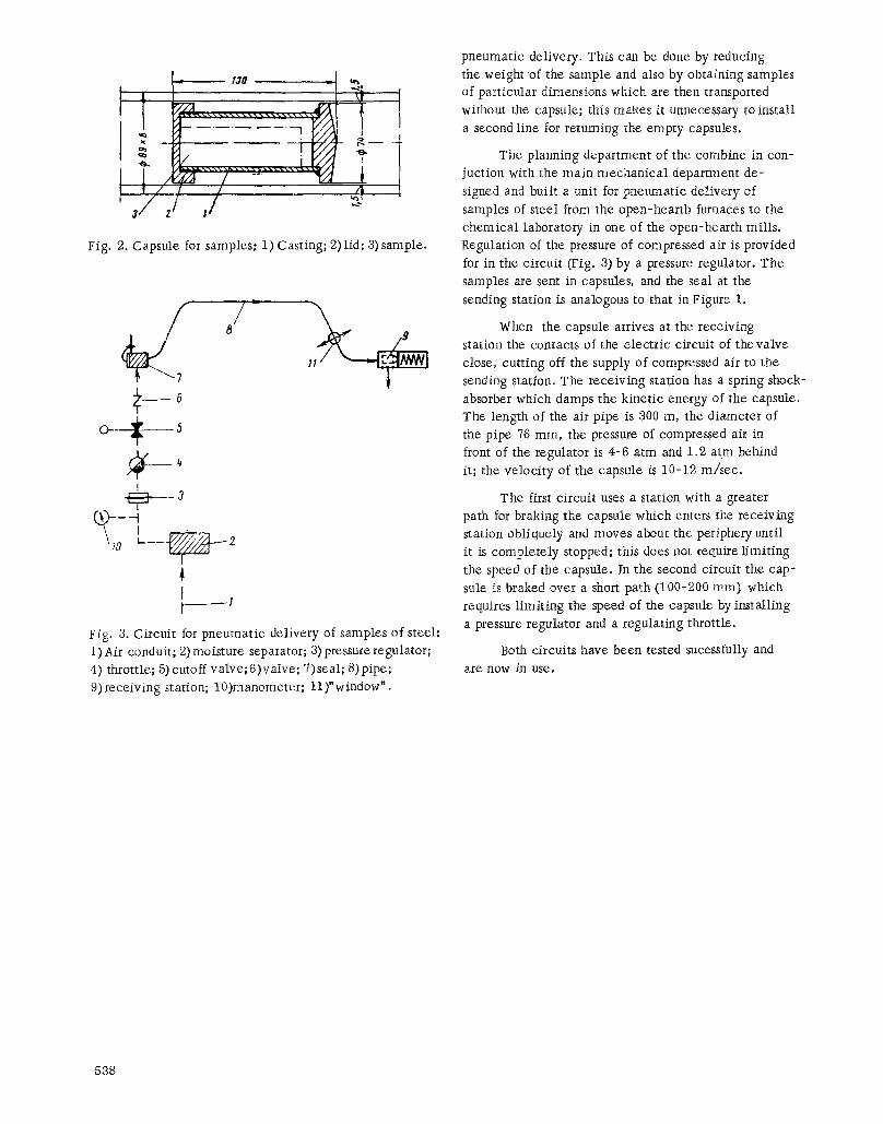
Fig. 2. Capsule for samples: 1) Casting; 2) lid; 3) sample.
O--- -~- 5
e --3
s0
4 1
Fig. 3. Circuit for pneumatic delivery of samples of steel: 1) Air conduit; 2) moisture separator; 3) pressure regulator; 4) throttle; 5)cutoff valve; 6)valve; 7)seal; 8)pipe; 9) receiving station; 10)manometer; 11)"window'.
pneumatic delivery. This can be done by reducing the weight o f the sample and also by obtaining samples of particular dimensions which are then transported without the capsule; this makes it unnecessary to install a second line for returning the empty capsules.
The planning department of the combine in con- juction with the main mechanical department de- signed and built a unit for pneumatic delivery of samples of steel from the open-hearth furnaces to the chemical laboratory in one of the open-hearth mills. Regulation of the pressure of compressed air is provided for in the circuit (Fig. 3) by a pressure regulator. The samples are sent in capsules, and the seal at the sending station is analogous to that in Figure 1.
When the capsule arrives at the receiving station the contacts of the electric circuit of the valve close, cutting off the supply of compressed air to the sending station. The receiving station has a spring shock- absorber which damps the kinetic energy of the capsule. The length of the air pipe is 300 m, the diameter of the pipe 76 ram, the pressure of compressed air in front of the regulator is 4-6 atm and 1.2 atm behind it; the velocity of the capsule is 10-12 m/sec.
The first circuit uses a station with a greater path for braking the capsule which enters the receiving station obliquely and moves about the periphery until it is completely stopped; this does not require limiting the speed of the capsule. In the second circuit the cap- sule is braked over a short path (100-200 ram) which requires limiting the speed of the capsule by installing a pressure regulator and a regulating throttle.
Both circuits have been tested sucessfully and are now in use.
538