pneumatic basic principles
TRANSCRIPT
01 - Pneumatic basic principles
- Pressure and vacuum- Boyle - Mariotte law- Gay - Lussac law- Flow characteristics- Coefficient "C" and "b"- Coefficient Kv- Nominal flow rate Q.Nn
01
IIThe overall dimensions and tecnical information are provided solely for information reasons and may be subject to change without notice
Pneumatic base principles
III
01
FP=S
P=
51bar= 10 Pa (100kPa)
=Pa (Pascal) N (Newton) 2m
2,5 bar absolute 1,5 bar relative
0 bar relative
-0,5 bar relative
Absolute vacuum 100%0 bar absolute -1,013 bar relative
0,5 bar absolute
1 bar absolute
Ab
so
lute
pre
ssu
re
Re
lati
ve
pre
ssu
re
Atm
osp
he
ric
pre
ssu
re
PRESSURE
Pressure is defined as the ratio between force and the surface area upon which it acts
International system measurement unit:
As a Pa is a very small unit, it is preferred to use bar:
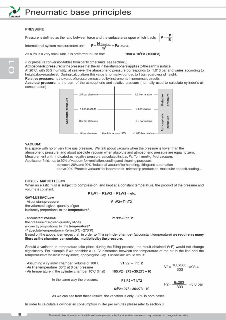
(For pressure conversion tables from bar to other units, see section 3),Atmospheric pressure: is the pressure that the air in the atmosphere applies to the earth’s surface.At 20°C, with 65% humidity, at sea level the atmospheric pressure corresponds to 1,013 bar and varies according to height above sea level. During calculations this value is normally rounded to 1 bar regardless of height.Relative pressure: is the value of pressure measured by instruments in pneumatic circuits.Absolute pressure: is the sum of the atmospheric and relative pressure (normally used to calculate cylinder’s air consumption)
VACUUM:Is a space with no or very little gas pressure. We talk about vacuum when the pressure is lower than the atmospheric pressure, and about absolute vacuum when absolute and atmospheric pressure are equal to zero.Measurement unit: indicated as negative pressure calculated in: bar, Pa, Torr, mmHg, % of vacuum.Application field: - up to 20% of vacuum for ventilation, cooling and cleaning purposes - between 20% and 99% "Industrial vacuum" for handling, lifting and automation - above 99% "Process vacuum" for laboratories , microchip production, molecular deposit coating…
BOYLE - MARIOTTE LawWhen an elastic fluid is subject to compression, and kept at a constant temperature, the product of the pressure and volume is constant.
P1xV1 = P2xV2 = P3xV3 = etc.GAY-LUSSAC Law- At constant pressure V1:V2=T1:T2 the volume of a given quantity of gas is directly proportional to the temperature*.
- at constant volume P1:P2=T1:T2the pressure of a given quantity of gas is directly proportional to the temperature* (* absolute temperature in Kelvin:0°C=273°K)Based on the above, it emerges that in order to fill a cylinder chamber (at constant temperature) we require as many liters as the chamber can contain, multiplied by the pressure.
Should a variation in temperature take place during the filling process, the result obtained (V·P) would not change significantly. For example if we consider a 20 C° difference between the temperature of the air in the line and the temperature of the air in the cylinder; applying the Gay - Lussac law would result: · Assuming a cylinder chamber volume of 100 I.· Air line temperature 30°C at 6 bar pressure· Air temperature in the cylinder chamber 10°C (final)
In the same way the pressure:
As we can see from these results the variation is only 6.6% in both cases.
In order to calculate a cylinder air consumption in liter per minutes please refer to section 8.
V1:V2 = T1:T2
100:V2=273+30:273+10
V2= =93,4l.100x283303
P1:P2=T1:T2
6:P2=273+30:273+10
P2= =5,6 bar6x283303
The overall dimensions and tecnical information are provided solely for information reasons and may be subject to change without notice
01
Pneumatic base principles
IV
P2P1
21
3
Flow characteristics
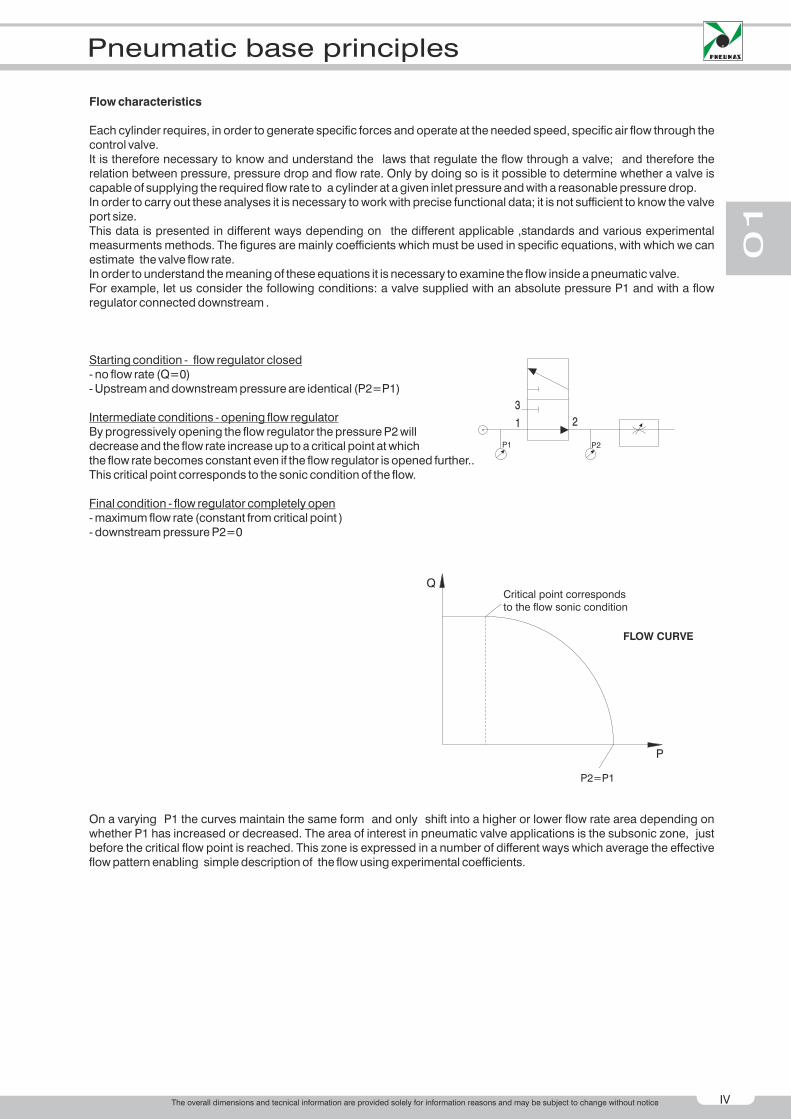
Each cylinder requires, in order to generate specific forces and operate at the needed speed, specific air flow through the control valve. It is therefore necessary to know and understand the laws that regulate the flow through a valve; and therefore the relation between pressure, pressure drop and flow rate. Only by doing so is it possible to determine whether a valve is capable of supplying the required flow rate to a cylinder at a given inlet pressure and with a reasonable pressure drop. In order to carry out these analyses it is necessary to work with precise functional data; it is not sufficient to know the valve port size.This data is presented in different ways depending on the different applicable ,standards and various experimental measurments methods. The figures are mainly coefficients which must be used in specific equations, with which we can estimate the valve flow rate.In order to understand the meaning of these equations it is necessary to examine the flow inside a pneumatic valve.For example, let us consider the following conditions: a valve supplied with an absolute pressure P1 and with a flow regulator connected downstream .
Starting condition - flow regulator closed- no flow rate (Q=0)- Upstream and downstream pressure are identical (P2=P1)
Intermediate conditions - opening flow regulatorBy progressively opening the flow regulator the pressure P2 will decrease and the flow rate increase up to a critical point at whichthe flow rate becomes constant even if the flow regulator is opened further..This critical point corresponds to the sonic condition of the flow.
Final condition - flow regulator completely open- maximum flow rate (constant from critical point )- downstream pressure P2=0
On a varying P1 the curves maintain the same form and only shift into a higher or lower flow rate area depending on whether P1 has increased or decreased. The area of interest in pneumatic valve applications is the subsonic zone, just before the critical flow point is reached. This zone is expressed in a number of different ways which average the effective flow pattern enabling simple description of the flow using experimental coefficients.
Critical point corresponds to the flow sonic condition
P2=P1
FLOW CURVE
Q
P
The overall dimensions and tecnical information are provided solely for information reasons and may be subject to change without notice

V
01
Pneumatic base principles
1M
1t
1d
M p
d2
M2
3d
CA B
10d 1
D E
3d 10d 1 2
F G
2
H L
VALVE COEFFICIENTS "C" e "B"
CETOP RP50P recommendation (derived from ISO 6358 standard) expresses flow rate in function of two experimental coefficients: - conductance C - critical pressure ratio b.
Conductance C = Q*/P1 is the ratio between maximum flow rate Q* and absolute inlet pressure P1 under sonic flow condition at a temperature of 20°C.Critical ratio b = P*2/P1 is the ratio between the output absolute pressure P2 and the inlet absolute pressure P1 at which the flow becomes sonic.The expression that represents an elliptic approximation of the relationship between pressure and flow follows:
Where: QN is the flow rate in dm /s at normal condition : 1,013 bar and 20°C;
C is the valve conductance
P1 is the inlet absolute pressure;
r is the ratio between downstream and upstream pressure (P2/P1);
b is the pressures critical ratio;
kt = is a corrective factor that consider the absolute inlet temperature T1;
T1= is the absolute temperature (t1 is the temperature in °C).
The experimental determination of the valve coefficient C & b is carried out with compressed air following standar-dised procedures and according to the scheme below.
CETOP test circuit
A Compressed air generator.B Pressure regulator to set upstream pressure P1.C Shut off valve.D Temperature sensor to check upstream temperature t 1, positioned in a low velocity area.E Pipe where the upstream pressure is measured F Test valve.G Pipe where the downstream pressure is measured .H Flow regulator to adjust the downstream pressure P2.L Flow meter.M1,M2 Pressure measuring equipment for upstream and downstream .MDP Pressure drop measuring equipment assuming P1-P2< 1 bar. Pipes E & G, used to measure the valve upstream and downstream pressure, must be sized according to the standard’s specifications and change in size depending on the valve port sizes; the position of the connection at which the measurements are taken depends on the pipe’s inner diameter.Conductance C is determined with the following equation, measuring the critical flow rate Q* through the valve, where upstream pressure P1 is constant and greater than 3 bar.
3
3
273+t1
293/T1
dm
3dm /s
s•bar
bar
Ö
C = Q*
P1 • Kt
2
QN = C • P1 • Kt • 1 - ( )
( )
(°K)
r - b1 - bÖ [1]
[2]
( )
( )
The overall dimensions and tecnical information are provided solely for information reasons and may be subject to change without notice

01
VI
Pneumatic base principles
Pressure critical ration b can be calculated using the following equation:
Considering a given constant pressure P1 it is necessary to proceed measuring the flow rate Q' corresponding to a pressure drop DP = P1-P2 = 1 bar.Equation 3 is used to calculate the critical ratio as it is difficult to experimentally identify the exact pressure P*2 at which the flow becomes sonic.The values of both the conductance C and the critical ratio b are experimentally calculated and are the average of the results obtained.Equation [1] is used to calculate the flow in subsonic conditions P2>b·P1 when values C ; b and the valve working conditions (P1, P2, T1) are known.Under sonic conditions , P2£ b · P1 the equation can be simplified and the maximum flow rate can be calculated as
follows:
Q* = C · P1 · kt
The hydraulic coefficient allows, using the equation Q=Kv The calculation of the flow rate of a fluid through a valveWhere: Q is the fluid flow rate in l/min Dp is the pressure drop inside the valve calculated in bar (P1 - P1) is the fluid density calculated in Kg/dm³
Kv is the hydraulic coefficient calculated in
Using these measurement units the flow rate coefficient Kv represents the flow rate (in liters) of water across the valve with a pressure drop of 1 bar.
The measurement are carried out using the standardised circuit below on which the connection ports are positioned according to the pipe inner bore size (norm VDE/VDI 2173).
Hydraulic circuit
3In some cases flow rate is measured in m /h which correspond a Kv measured
To obtain Kv expressed in it is sufficient to multiply the Kv value expressed in
By the coefficient 16,66.
The coefficient kv is perfectly suitable to express the flow rate of fluids but only gives approximate values in case of compressed air .
Experiences gained in hydraulic environments can be inferred in the pneumatic field, bearing in mind the difference in density, and assuming that the air flow will generate the same pressure drops and flow reductions as waterIt is therefore possible to calculate reliable values for compressed air using flow coefficients Kv obtained from experiments with water.
P
1d
20d
d 1P
5d10d
VALVEUNDER TEST
2P 
b = 1 - D P___
1 Ö ___([ [(Q'P1 1- 1- Q*
2 [3]
[4]
[5]
kg
dm³•bar ________
½
min
I __ ( (
kg
dm³•bar ________
½
min
I __ ( ( kg
dm³•bar
________ ½
h
m³ __ ( (
HYDRAULIC COEFFICIENT KV
Dp
¶Ö (l/min)
The overall dimensions and tecnical information are provided solely for information reasons and may be subject to change without notice
VII
01
Pneumatic base principles
To define the flow rate Qn through a valve at a given constant absolute inlet pressure P1, regardless of fluctuations of the downstream absolute pressure P2, refer to the equation below :
where: Qn is the flow rate in volume I/min;
Kv is the hydraulic coefficient
Tn is the absolute reference temperature;T1 is the inlet absolute temperature in °K;P2 is the downstream absolute pressure in bar;DP is the pressure drop P1 - P2 in bar.
Equation [6] is real up to P = therefore P2 =
For lower P2 values the flow rate is considered to be constant, corresponding to the sonic flow rate Q*n given by the following equation:
Q*N = 14,3 · KV · P1
The nominal flow rate is the flow volume (at normal conditions) that passes through a valve with an upstream pressure P1=6bar (7 bar absolute pressure) and a pressure drop of 1 bar, corresponding to a downstream relative pressure P2 of 5bar (6 bar absolute pressure).Normally the nominal flow rate is expressed in l/min and can be easily deduced from an experimental flow curve drawn for a upstream pressure of 6 bar (relative).Nominal flow rate can be useful for a preliminary assesment of the performances of different valves but in reality can be used only if the working conditions are the same as those mentioned before. In order to be able to compare valve charactersistics which are expressed in different coefficients it is possible to use conversion equations.Given the C and b coefficient, it is possible to determine the nominal flow rate using the following equation:
QNn = 420 • C •
Where : QNn = is in I/min and C in
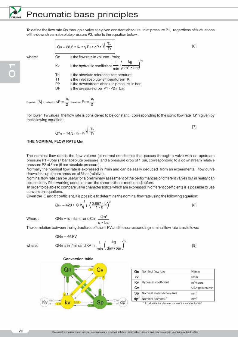
The correlation between the hydraulic coefficient KV and the corresponding nominal flow rate is as follows:
QNn = 66 KV
where: QNn is in I/min and KV in
[6]
[7]
[8]
[9]
QN = 28,6 • Kv • P2 • DP • Ö Ö Tn
T1
Ö Tn
T1
P1
2
P1
2
THE NOMINAL FLOW RATE QNn
2
1 - ( ) 0,857 - b1 - bÖ
s • bar
dm³
kg
dm³•bar
½
min
I ( (
kg
dm³ • bar
½
min
I ( (
Conversion table
Qn Nominal flow rate Nl/min
kv l/min
Kv m3/hours
Cv USA gallons/min
Sp Nominal inner section area mm2
dp2
Nominal diameter 2 mm2
2 2* to calculate the diameter dp (mm ) square root of dp
Hydraulic coefficient
D
The overall dimensions and tecnical information are provided solely for information reasons and may be subject to change without notice