pmcs network and device configurator - ge grid … · client applications ... the pmcs network and...
TRANSCRIPT
GE MULTILIN TM PMCS Network and Device Configurator
DDE/OPC Server User’s Guide GEH-6510
GE Multilin PMCS
DDE Server User’s Guide • i
Notice
The information contained in this document is subject to change without notice. GE makes no warranty of any kind with regard to this material, including, but not limited to, the implied warranties of merchantability and fitness for a particular purpose. GE shall not be liable for errors contained herein or incidental consequential damages in connection with the furnishing, performance, or use of this material.
This document contains proprietary information, which is protected by copyright. All rights are reserved. No part of this document may be photocopied or otherwise reproduced without consent of GE.
Copyright ©2003-2005 by GE
Published in a limited copyright sense and all rights, including trade secrets, are reserved.
Document Edition - First 03/04 Second 09/04
Third 05/05
The following are products of General Electric Company:
POWER LEADERTM Meter 239 Motor Protection Relay GE Fanuc Series 90/30 PLC POWER LEADER Modbus Monitor 269 Plus Motor Management Relay GE Fanuc Series 90/70 PLC POWER LEADER Electronic Power Meter
369 Motor Management Relay Power Quality Meter (PQM)
Spectra MicroVersaTrip 469 Motor Management Relay EPM 7300 Electronic Power Meter EPM 7600 Electronic Power Meter EPM 7500 Electronic Power Meter EPM 7330 Electronic Power Meter Enhanced MicroVersaTrip-C 489 Generator Management Relay EPM 7700 Electronic Power Meter Enhanced MicroVersaTrip-D 565 Feeder Management Relay EPM 3710 Electronic Power Meter MDP Overcurrent Relay 735 Feeder Relay EPM 3720 Electronic Power Meter 750/760 Feeder Management Relay SR745 Transformer Management Relay Spectra Electronic Control Module Universal Relay EPM7430D/EPM7450D (Futura) Motor Manager II (MMII) GE-Zenith MX200 (Microprocessor Controller)
GE-Zenith Generator PLC (Series 90-70)
EPM5300P/EPM5200P
EPM5350P (DMMS350) EPM5000P (DMWH300) EPM9450Q (Nexus1250) EPM9650Q (Nexus1252) Power Quality Meter II (PQMII) F650 Bay Controller Remote RTD Motor Manager III (MMIII) 737 Feeder Relay Entellisys Low Voltage Switchgear MIFII Feeder Management Relay EPM 2000 Digital Power Meter EPM 1000 Sub-Meter EPM 4000 Sub-Meter EPM 6000 Multifunction Electricity
Meter GE-Zenith MX250 GE-Zenith MX150
Multilin 269+ Motor Management Relay® is a registered trademark of Multilin Inc., and Multilin SR489 Generator Management Relay™ and Multilin SR745 Transformer Management Relay™ are trademarks of Multilin Inc. Microsoft, Microsoft Excel, and Microsoft PowerPoint are registered trademarks, and Windows 2000 SP3 / SP4 or Windows XP SP1 is a trademark of Microsoft Corporation.
US Pat Nos 5,768,148; 5,764,155; 5,862,391
ii • DDE Server User’s Guide
Back to Main Menu
Contents
Chapter One - Introduction 1 Welcome....................................................................................................................................1 About DDE................................................................................................................................2 About the PMCS DDE Server ...................................................................................................2 Installation .................................................................................................................................3
Chapter Two - Overview 5 About PMCS..............................................................................................................................5 Devices ......................................................................................................................................6 Networks....................................................................................................................................7 PMCS DDE Server ....................................................................................................................7 Client Applications ....................................................................................................................7 What’s Next...............................................................................................................................7
Chapter Three - Getting Started 8 Introduction ...............................................................................................................................8 First-Time Configuration...........................................................................................................8
Communication Ports ..................................................................................................8 Device Configuration ..................................................................................................8
Launching the Program .............................................................................................................9 What’s on the DDE Server Screen? ..........................................................................................9 Menu Bar ...................................................................................................................................9
Menu Conventions ....................................................................................................10 Configuring Communication ports ..........................................................................................10 Configuring the Devices ..........................................................................................................16 Starting the Server ...................................................................................................................19 Displaying I/O Traffic .............................................................................................................19
Chapter Four - Menus and Toolbars 25 System Menu ...........................................................................................................................25 Tab Bar ....................................................................................................................................25
Main Tab ...................................................................................................................26 Log Tab .....................................................................................................................27
Server Menu ............................................................................................................................28 Run ............................................................................................................................28 Stop ...........................................................................................................................28 Suspend Protocol/Resume Protocol ..........................................................................29 Print I/O Traffic.........................................................................................................29 Exit ............................................................................................................................29
View Menu ..............................................................................................................................29
DDE Server User’s Guide • iii
I/O Traffic Display ....................................................................................................29 Clear Display .............................................................................................................32 Save Display To File .................................................................................................32 Port Statistics .............................................................................................................32 Configuration.............................................................................................................33
Configure Menu.......................................................................................................................33 Configure...................................................................................................................34
Reports Menu...........................................................................................................................45 Configuration.............................................................................................................45 Active Links ..............................................................................................................45 OPC Server Status .....................................................................................................45
Help Menu ...............................................................................................................................46 Toolbar.....................................................................................................................................46
Chapter Five - Troubleshooting 47 Trouble-Shooting the PMCS DDE Server...............................................................................47
WWLogger................................................................................................................47 Communications – Client to Server .........................................................................................48 Communications – Server to Device .......................................................................................49 Trouble-Shooting Flowchart....................................................................................................50 Trouble-Shooting Chart ...........................................................................................................52 Error Messages ........................................................................................................................52
Chapter Six - Advanced Options 59 Warning ...................................................................................................................................59 Device Type Information – Adding Generic Devices .............................................................59
Add Default Type ......................................................................................................60 Delete.........................................................................................................................60 Function Codes..........................................................................................................61 Register Map .............................................................................................................62 Mnemonics ................................................................................................................67
Optimizing Server Performance ..............................................................................................69 Server Operational Parameters ..................................................................................69 PMCS DDE Server .ini File ......................................................................................70
Appendix A – Register Addressing Conventions 73 Data-Addressing Conventions .................................................................................................73
Standard Data Organization ......................................................................................74 Special Naming Conventions ....................................................................................75 Register Array Format ...............................................................................................77
Glossary of Terms 79 Terms You Should Know ........................................................................................................79
Index 81
iv • DDE Server User’s Guide

(This page left blank intentionally)
DDE Server User’s Guide • v

Chapter One - Introduction
Welcome The PMCS Network and Device Configurator with DDE Server is the heart of a MULTILINTM PMCS, a tool that helps you increase productivity, reduce downtime, and improve power quality by automatically collecting the wealth of data available from devices in your power network. You select data to monitor and configure the PMCS DDE Server to communicate with the selected devices in your system. The PMCS DDE Server collects the requested data and supplies it to your choice of software applications for analysis and trending.
The information gathered by the PMCS DDE Server, when analyzed by the appropriate client software, provides you with the following benefits:
• Improved power quality — Identify sources of “dirty” power, otherwise invisible, and take corrective action to save wear, tear, and possible damage to critical equipment.
• Faster corrective maintenance — Quickly pinpoint the root causes of problems using time-stamped alarms and event-sequence logs.
• Higher productivity — Free up maintenance and repair personnel to perform other duties.
• Less downtime — Identify and correct problems before they lead to loss of power and/or costly damage to loads such as production equipment and computers.
• Increased safety — Provide a central source of information, reducing the need for physical contact with equipment and shop-floor presence.
The PMCS DDE Server collects and communicates metering, status, event, and alarm data from metering, control, and protection devices on the network to other PMCS software tools, such as third party HMI development tools, Event Logger, or Waveform Capture. The data can easily be imported into spreadsheets, such as Microsoft Excel, for analysis and presentation.
The PMCS DDE Server allows you to collect data from any PMCS -compatible device; you can also custom-configure your own device types to accommodate additional third-party devices.1
1 The DDE Server can be configured to collect data from any device that supports Modbus RTU register-based communications.
DDE Server User’s Guide Chapter One - Introduction • 1
About DDE DDE is the acronym for Dynamic Data Exchange, a communications protocol that allows independently developed Microsoft Windows 2000 SP3 / SP4 or Windows XP SP1 programs to share data and instructions with each other.
DDE implements a client-server relationship between two concurrently running programs. The server application provides data and accepts requests from any other applications interested in its data. The applications requesting the data are called clients.
Requests for data can be of two types: one-time requests or permanent data links. With one-time requests, the client program requests a “snapshot” of the desired data from the server application. An example of a one-time request is a program such as Excel running a report-generating macro. The macro opens a temporary link to another application, requests specific data, closes the link, and uses the data to generate the report.
Permanent data links are called hot links. When a client application sets up a hot link to another application, it requests the server application to advise the client whenever a specific item’s data value changes. Hot links remain active until either the client or server program terminates the link. Hot links are an efficient means of exchanging data because, once the link has been established, no communication occurs until the specified data value changes.
The DDE protocol specification includes standardized formats for messages to be exchanged between DDE-compliant applications (such as Microsoft Excel).
About the PMCS DDE Server The PMCS Dynamic Data Exchange (DDE) Server is a Windows 2000 SP3 / SP4 or Windows XP SP1 application that allows other Windows 2000 SP3 / SP4 or Windows XP SP1 applications to access data from GE devices and third-party devices.
It communicates directly with other PMCS applications, such as third-party HMI tools to form a powerful and flexible power-management system. The PMCS DDE Server acts as the bridge between Modbus RTU or Ethernet power-management networks and DDE-compliant software applications for display, analysis, and control.
The PMCS DDE Server application program is named PMCS-RS485 (GE32MODB -RS-485 Modbus RTU version), PMCS –TCPIP (GE32MTCP -TCP/IP Modbus version).
The PMCS DDE Server is easy to use. It provides a Windows graphical user interface with a toolbar and pull-down menus for quick and easy device definition, configuration, I/O display, and report generation.
The DDE Server supports both DDE for sharing data with applications on the same computer and NetDDE for sharing data with other computers in a local-area network (LAN).
Server with OPC Interfaces DDEServer supports OPC interfaces. These servers can be used with third party software clients, which are OPC compliant.
2 • Chapter One - Introduction DDE Server User’s Guide
Installation To install the PMCS DDE Server, refer to Read This Book First, which contains installation procedures for all MULTILINTM system and application software packages. This guide accompanied the PMCS software package, and is also contained (as a PDF file) on the PMCS software installation CD-ROM.
Installing the PMCS Network and Device Configurator software creates the following directory in the root directory of the specified drive:
\ge_pmcs\server\ (for Modbus version of the DDE Server)
\ge_pmcs\ge32mtcp\ (for Modbus TCP/IP version of the DDE Server)
Although you do not need to know the directory structure to use the PMCS DDE Server, you should know where the files are located on your hard drives so that you do not accidentally move or erase them.
DDE Server User’s Guide Chapter One - Introduction • 3

Chapter Two - Overview
About PMCS GE Multilin’s PMCS consists of four basic parts: the power-management devices, the network connecting the devices to the host, the PMCS DDE Servers (PMCS-RS485 and PMCS-TCPIP. From here on in the document wherever PMCS DDE Server is referred it could be any one of the mentioned two, either RS485 version or TCPIP version) software, and the client applications. This section provides an overview of the parts and their functions.
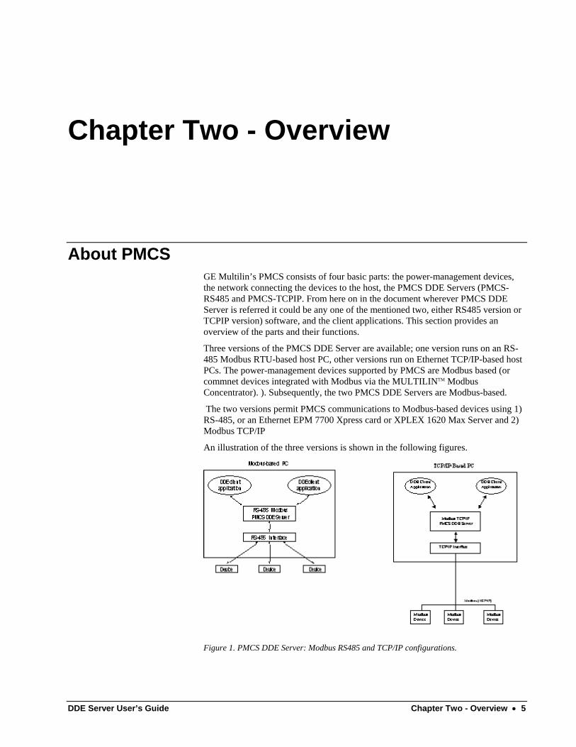
Three versions of the PMCS DDE Server are available; one version runs on an RS-485 Modbus RTU-based host PC, other versions run on Ethernet TCP/IP-based host PCs. The power-management devices supported by PMCS are Modbus based (or commnet devices integrated with Modbus via the MULTILINTM Modbus Concentrator). ). Subsequently, the two PMCS DDE Servers are Modbus-based.
The two versions permit PMCS communications to Modbus-based devices using 1) RS-485, or an Ethernet EPM 7700 Xpress card or XPLEX 1620 Max Server and 2) Modbus TCP/IP
An illustration of the three versions is shown in the following figures.
Figure 1. PMCS DDE Server: Modbus RS485 and TCP/IP configurations.
DDE Server User’s Guide Chapter Two - Overview • 5
The differences between the two versions of the Server are minor and, except where noted the software is functionally identical. The Modbus-host version of the PMCS DDE Server is the focus in this document; differences in the TCP/IP versions are noted when present. The Modbus version of the server may be used to service local RS-485 ports directly from the host PC, as well as remote serial ports accessed via the Ethernet Gateway over TCP/IP communications. Another variant of the DDE server works in the same way as the Modbus RS-485 DDE server on EI Protocol.
In the interest of brevity, we’ll refer to the PMCS Network and Device Configurator with DDE Server, as “the PMCS –RS485” or simply “the Communication Server” – be aware that this document describes only the PMCS-RS485 or TCPIP. The information herein is not intended to apply to other DDE servers.
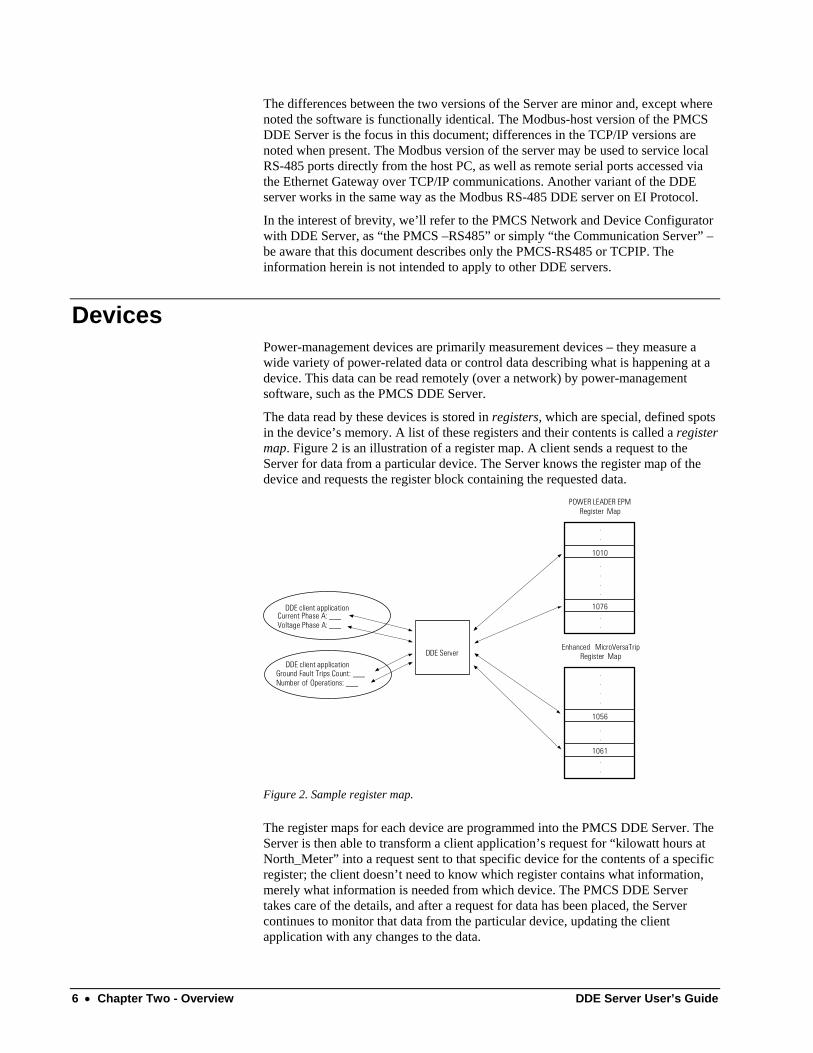
Devices Power-management devices are primarily measurement devices – they measure a wide variety of power-related data or control data describing what is happening at a device. This data can be read remotely (over a network) by power-management software, such as the PMCS DDE Server.
The data read by these devices is stored in registers, which are special, defined spots in the device’s memory. A list of these registers and their contents is called a register map. Figure 2 is an illustration of a register map. A client sends a request to the Server for data from a particular device. The Server knows the register map of the device and requests the register block containing the requested data.
DDE Server
P O W E R L E A D E R
E P M
R e g i s t e r M a p
1 0 1 0
1 0 7 6
.
.
.
.
.
.
.
. D D E
c l i e n t
a p plication
C u r r e n t P h a s e
A :
___
V o l t a g e P h a s e
A :
___
D D E c l i e n t
a p plication
G r o u n d F a u l t
T r i p s
Count:
___
N u m b e r o f
O p e r ations:
___
1 0 5 6
1 0 6 1
Enh a n c e d
M i c r o V e r s a T r i p R e g i s t e r
M a p
.
.
.
.
.
.
.
. Figure 2. Sample register map.
The register maps for each device are programmed into the PMCS DDE Server. The Server is then able to transform a client application’s request for “kilowatt hours at North_Meter” into a request sent to that specific device for the contents of a specific register; the client doesn’t need to know which register contains what information, merely what information is needed from which device. The PMCS DDE Server takes care of the details, and after a request for data has been placed, the Server continues to monitor that data from the particular device, updating the client application with any changes to the data.
6 • Chapter Two - Overview DDE Server User’s Guide
The register maps of the MULTILINTM family of devices and a variety of other devices are pre-configured in the Server. If you wish to use a device whose register map is not pre-configured, you need to supply the appropriate register information to the Server so it will know where in the device’s memory to get the information you are requesting. We’ll refer to these as generic devices since we don’t know what they might be. Defining new device types is detailed in Chapter 6, Advanced Options.
Networks The network consists of an interface at the host PC and the cables connecting the various devices to the host. There are physical requirements and limitations to the networks, which are explained in GEH-6502, Network Architecture Guide.
PMCS DDE Server The PMCS DDE Server has two basic functions: it collects data from attached devices and it provides data to client applications (both on the host PC and on networked PCs).
The PMCS DDE Server keeps track of the devices attached to the PMCS networks, listens for requests for data from client applications, and, at specified intervals, polls the requested data from the appropriate devices and reports it back to the clients. The Server does not continuously poll all data from each device unless it is told to do so; to do this would require enormous network bandwidth and result in degraded performance. Instead, the PMCS DDE Server retrieves only the specific data that client applications have requested.
Client Applications Client applications request specific data from the PMCS DDE Server and then provide calculations, trending, and display of the data on screen and/or printer.
Various client applications are available to serve different needs. Event Logger, Waveform Capture, and Cost Allocation are just a few of the applications that are fully optimized for PMCS.
Any DDE-compliant application can request data from the PMCS DDE Server by initiating a “conversation” with the server and providing the correct information phrased in DDE format – i.e., what data from which device.
A common example of a DDE-compliant application used to analyze data from the PMCS DDE Server is Microsoft Excel, which provides data manipulation and analysis tools. However, any DDE-compliant application may retrieve from the PMCS DDE Server. For instance, a presentation on the power consumption at an industrial facility might be created using Microsoft PowerPoint, charting power consumption data requested from the PMCS DDE Server.
What’s Next You’ve now learned about the four major parts of PMCS – next you’ll learn how to configure your PMCS DDE Server.
DDE Server User’s Guide Chapter Two - Overview • 7
Chapter Three - Getting Started
Introduction In this chapter, we’ll explain how to configure the PMCS DDE Server for use: starting the software, understanding what’s on the screen, setting it up for communications, and telling it what devices are connected and how to communicate with them.
This chapter is a functional tutorial rather than a comprehensive reference. Chapter 4, Menus and Toolbars, provides in-depth descriptions of the menus and each function available.
This manual also assumes that the hardware side of the PMCS network has been set up and wired correctly, and that the host PC that PMCS will run on has been properly connected to the network.
First-Time Configuration As we mentioned in Chapter 2, the PMCS DDE Server collects data from devices connected across a network. We’ll have to set up our Server to communicate correctly with the network and recognize the devices we’ve attached.
First-time configuration involves two basic procedures: setting up communication ports and then configuring devices. We’ll provide examples of each procedure.
Communication Ports You must identify the communication settings for each of the Server’s communication ports: baud rates, parity, stop bits, etc. This permits the Server to communicate correctly with the attached networks. (Note for Ethernet users: configuration of Ethernet communications is slightly different and will be covered later in the document.)
Device Configuration Here you’ll be telling the PMCS DDE Server the specific devices that are connected to the network by defining topics for the Server to look at. A topic consists of a device name, the number of the communication port the device is connected to, the Modbus address of the device, the device type, and related scan-interval information. After this information is entered into the Server, the Server knows which data you want, how often you want it, and where to get it.
8 • Chapter Three - Getting Started DDE Server User’s Guide
Launching the Program First, let’s launch the program. To start the PMCS DDE Server, open the PMCS program group in Windows. The PMCS DDE Server program icon (Modbus version) is shown below. The icon for other versions of the PMCS DDE Server software is identical with the exception of the application name, which may be PMCS – TCPIP depending on your particular network configuration. Double-click on the icon to start the PMCS DDE Server program.
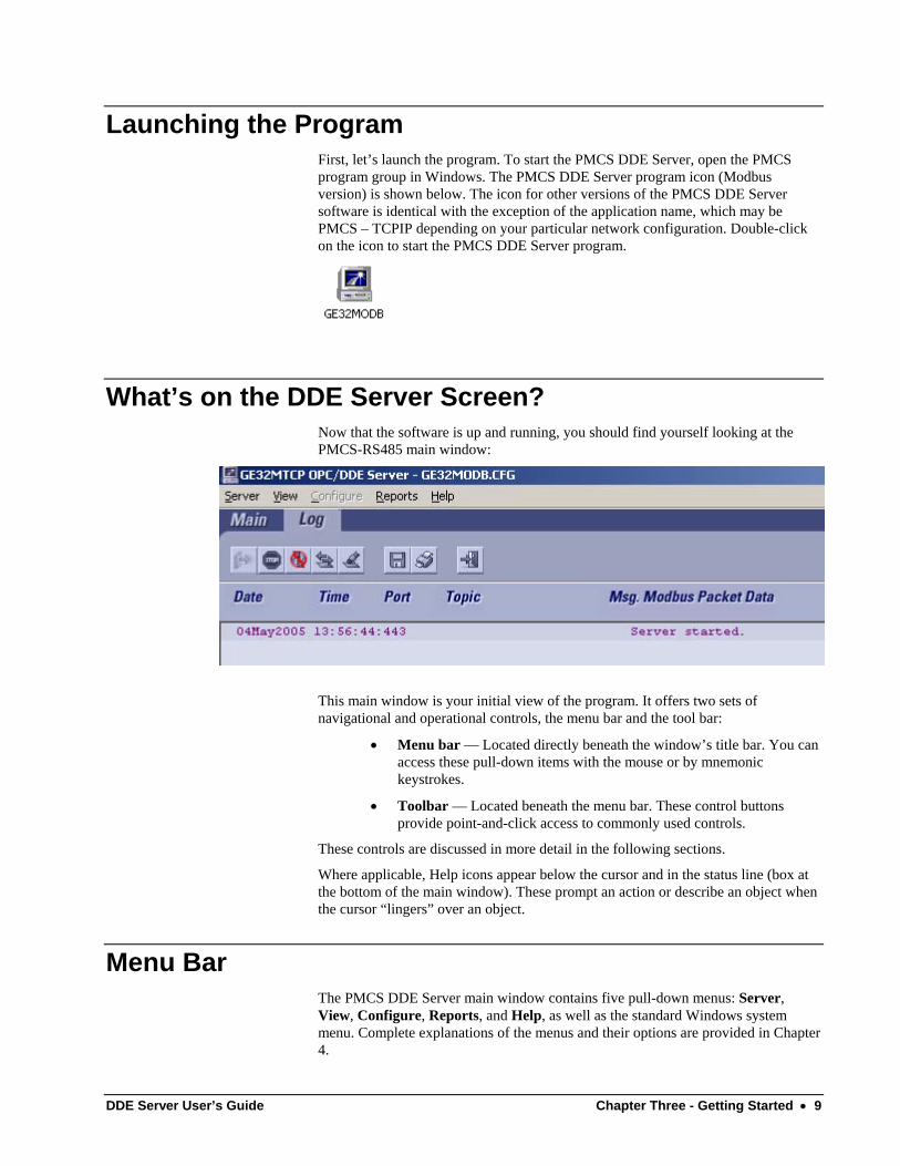
What’s on the DDE Server Screen? Now that the software is up and running, you should find yourself looking at the PMCS-RS485 main window:
This main window is your initial view of the program. It offers two sets of navigational and operational controls, the menu bar and the tool bar:
• Menu bar — Located directly beneath the window’s title bar. You can access these pull-down items with the mouse or by mnemonic keystrokes.
• Toolbar — Located beneath the menu bar. These control buttons provide point-and-click access to commonly used controls.
These controls are discussed in more detail in the following sections.
Where applicable, Help icons appear below the cursor and in the status line (box at the bottom of the main window). These prompt an action or describe an object when the cursor “lingers” over an object.
Menu Bar The PMCS DDE Server main window contains five pull-down menus: Server, View, Configure, Reports, and Help, as well as the standard Windows system menu. Complete explanations of the menus and their options are provided in Chapter 4.
DDE Server User’s Guide Chapter Three - Getting Started • 9
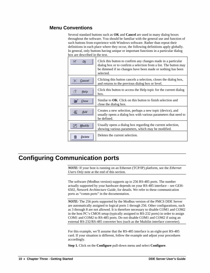
Menu Conventions Several standard buttons such as OK and Cancel are used in many dialog boxes throughout the software. You should be familiar with the general use and function of such buttons from experience with Windows software. Rather than repeat their definitions in each place where they occur, the following definitions apply globally. In general, only buttons having unique or important functions in a particular dialog box are described in the text.
Click this button to confirm any changes made in a particular dialog box or to confirm a selection from a list. The button may be dimmed if no changes have been made or nothing has been selected.
Clicking this button cancels a selection, closes the dialog box, and returns to the previous dialog box or level.
Click this button to access the Help topic for the current dialog box.
Similar to OK. Click on this button to finish selection and close the dialog box.
Creates a new selection, perhaps a new topic (device), and usually opens a dialog box with various parameters that need to be defined.
Usually opens a dialog box regarding the current selection, showing various parameters, which may be modified.
Deletes the current selection.
Configuring Communication ports NOTE: If your host is running on an Ethernet (TCP/IP) platform, see the Ethernet Users Only note at the end of this section.
The software (Modbus version) supports up to 256 RS-485 ports. The number actually supported by your hardware depends on your RS-485 interface – see GEH-6502, Network Architecture Guide, for details. We refer to these communication ports as “comm ports” in the documentation.
NOTE: The 256 ports supported by the Modbus version of the PMCS DDE Server are automatically assigned to logical ports 1 through 256. Other configurations, such as 3 through 8 are not allowed. It is therefore necessary to disable COM1 and COM2 in the host PC’s CMOS setup (typically assigned to RS-232 ports) in order to assign COM1 and COM2 to RS-485 ports. Do not disable COM1 and COM2 if using an external RS-232/RS-485 converter box (such as the Multilin interface converter).
For this example, we’ll assume that the RS-485 interface is an eight-port RS-485 card. If your situation is different, follow the example and adjust your procedures accordingly.
Step 1. Click on the Configure pull-down menu and select Configure.
10 • Chapter Three - Getting Started DDE Server User’s Guide
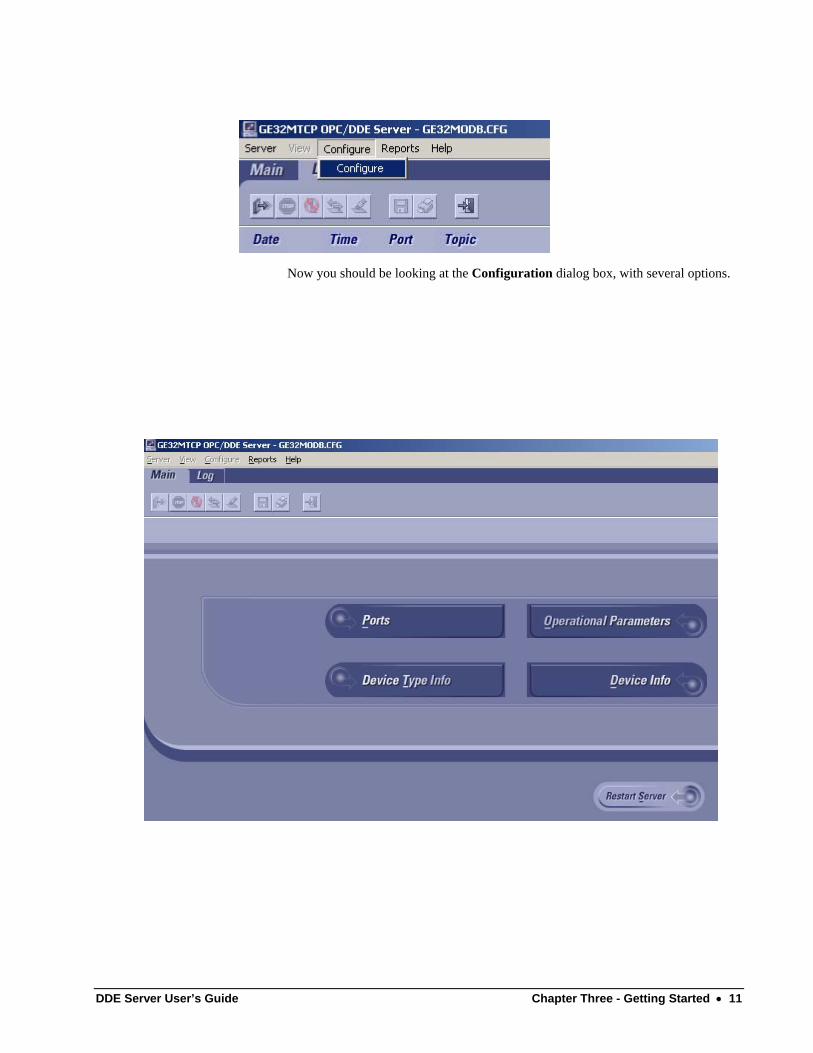
Now you should be looking at the Configuration dialog box, with several options.
DDE Server User’s Guide Chapter Three - Getting Started • 11
We want to configure communication ports, so click on the Ports button.
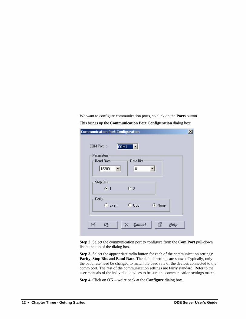
This brings up the Communication Port Configuration dialog box:
Step 2. Select the communication port to configure from the Com Port pull-down list at the top of the dialog box.
Step 3. Select the appropriate radio button for each of the communication settings: Parity, Stop Bits and Baud Rate. The default settings are shown. Typically, only the baud rate need be changed to match the baud rate of the devices connected to the comm port. The rest of the communication settings are fairly standard. Refer to the user manuals of the individual devices to be sure the communication settings match.
Step 4. Click on OK – we’re back at the Configure dialog box.
12 • Chapter Three - Getting Started DDE Server User’s Guide
That’s it; you now know how to configure a communication port. Go ahead and configure any other communication ports that will be used, following the procedure above.
Hint: You don’t need to leave the Communication Port Configuration dialog box to configure multiple ports. Select a port from the pull-down list, make your changes, then you can select another port from the pull-down list and configure it as well. Configure as many ports as you need to, then click OK to save your changes and return to the Configure dialog box.
Ethernet Users Only:
EPM 7700 Xpress Card or XPLEX 1620 Max Server Users
If your host software is running on an Ethernet-based PC, you may be using a special hardware gateway to communicate to your RS-485 ports This extra layer of hardware entails some minor differences in the configuration software, specifically in the Ports dialog boxes. These differences are explained below.
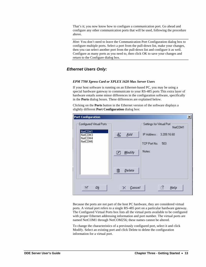
Clicking on the Ports button in the Ethernet version of the software displays a slightly different Port Configuration dialog box:
Because the ports are not part of the host PC hardware, they are considered virtual ports. A virtual port refers to a single RS-485 port on a particular hardware gateway. The Configured Virtual Ports box lists all the virtual ports available to be configured with proper Ethernet addressing information and port number. The virtual ports are named NetCOM1 through NetCOM256; these names cannot be altered.
To change the characteristics of a previously configured port, select it and click Modify. Select an existing port and click Delete to delete the configuration information for a virtual port.
DDE Server User’s Guide Chapter Three - Getting Started • 13
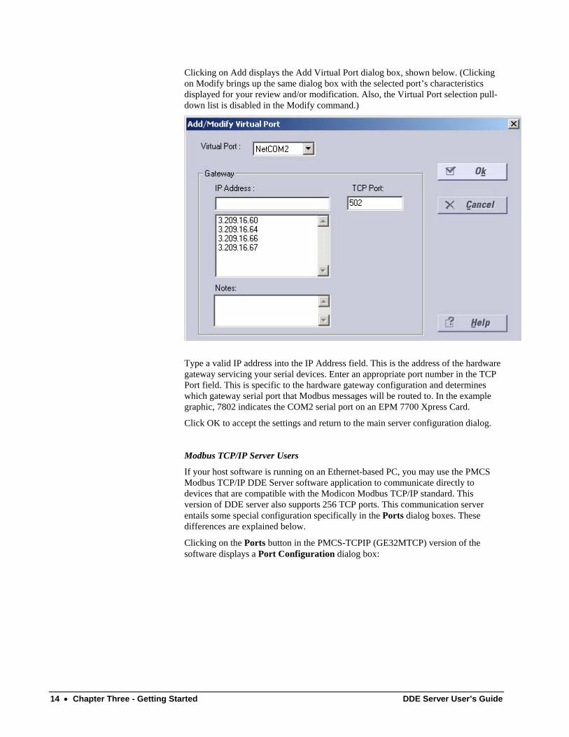
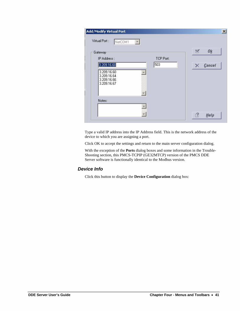
Clicking on Add displays the Add Virtual Port dialog box, shown below. (Clicking on Modify brings up the same dialog box with the selected port’s characteristics displayed for your review and/or modification. Also, the Virtual Port selection pull-down list is disabled in the Modify command.)
Type a valid IP address into the IP Address field. This is the address of the hardware gateway servicing your serial devices. Enter an appropriate port number in the TCP Port field. This is specific to the hardware gateway configuration and determines which gateway serial port that Modbus messages will be routed to. In the example graphic, 7802 indicates the COM2 serial port on an EPM 7700 Xpress Card.
Click OK to accept the settings and return to the main server configuration dialog.
Modbus TCP/IP Server Users
If your host software is running on an Ethernet-based PC, you may use the PMCS Modbus TCP/IP DDE Server software application to communicate directly to devices that are compatible with the Modicon Modbus TCP/IP standard. This version of DDE server also supports 256 TCP ports. This communication server entails some special configuration specifically in the Ports dialog boxes. These differences are explained below.
Clicking on the Ports button in the PMCS-TCPIP (GE32MTCP) version of the software displays a Port Configuration dialog box:
14 • Chapter Three - Getting Started DDE Server User’s Guide
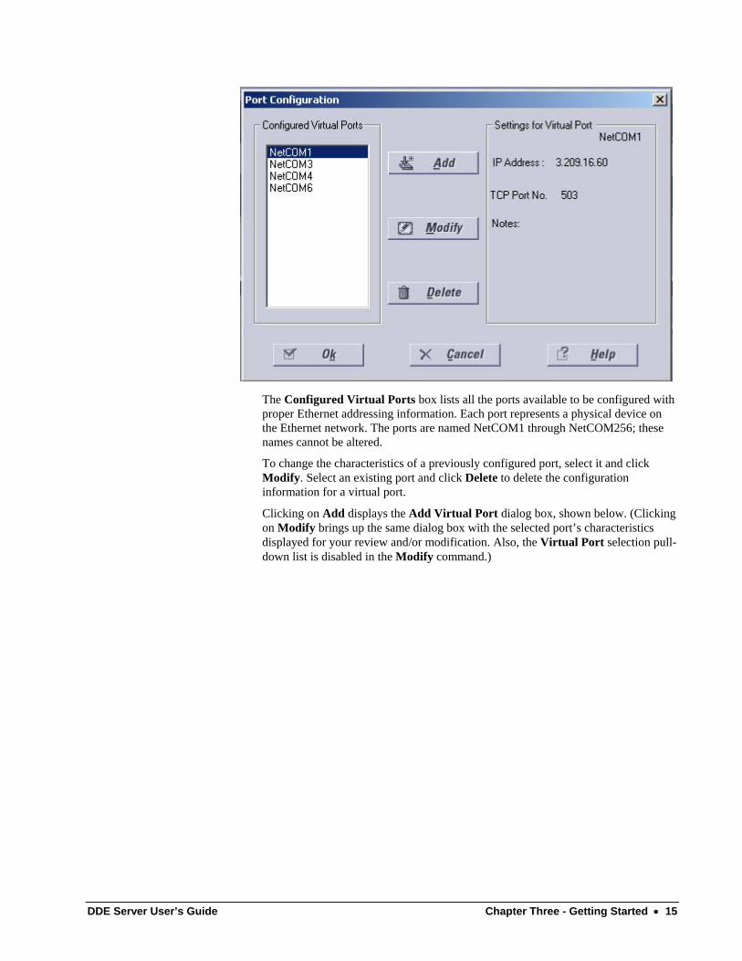
The Configured Virtual Ports box lists all the ports available to be configured with proper Ethernet addressing information. Each port represents a physical device on the Ethernet network. The ports are named NetCOM1 through NetCOM256; these names cannot be altered.
To change the characteristics of a previously configured port, select it and click Modify. Select an existing port and click Delete to delete the configuration information for a virtual port.
Clicking on Add displays the Add Virtual Port dialog box, shown below. (Clicking on Modify brings up the same dialog box with the selected port’s characteristics displayed for your review and/or modification. Also, the Virtual Port selection pull-down list is disabled in the Modify command.)
DDE Server User’s Guide Chapter Three - Getting Started • 15
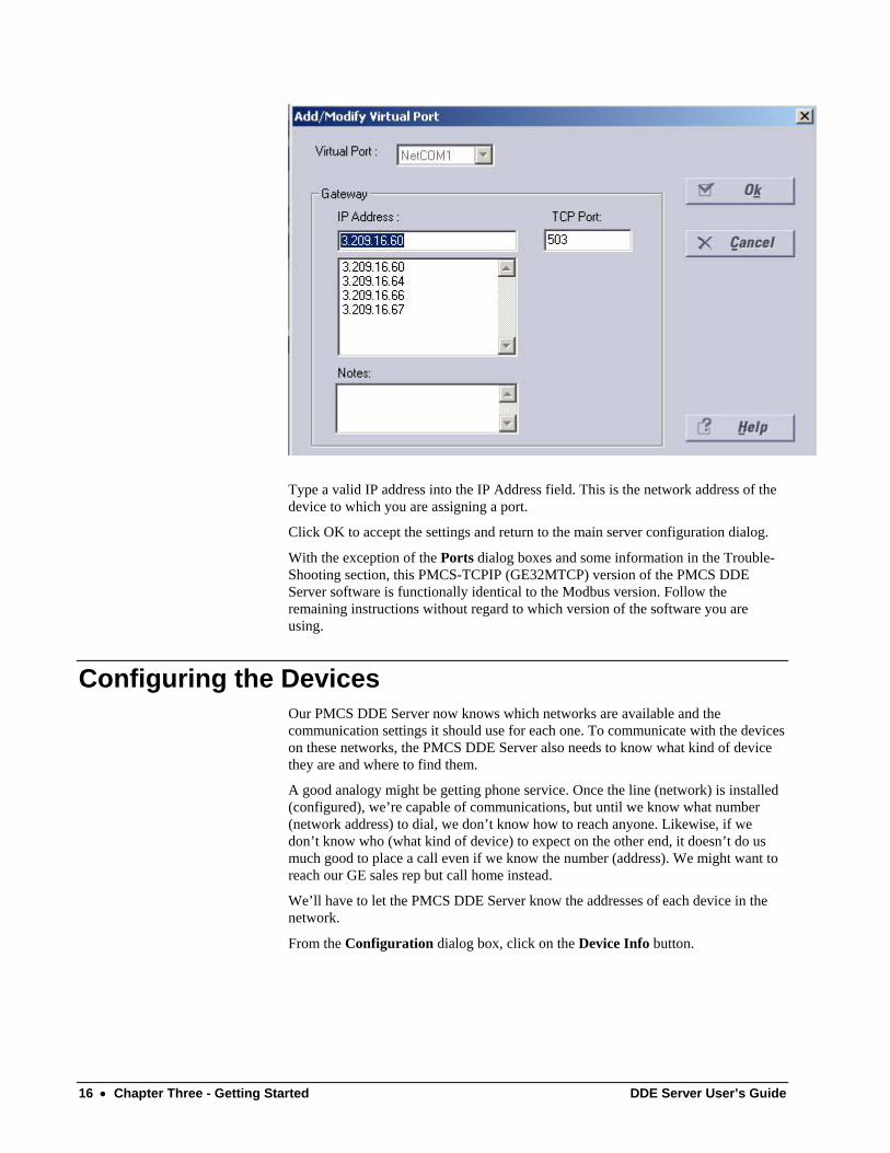
Type a valid IP address into the IP Address field. This is the network address of the device to which you are assigning a port.
Click OK to accept the settings and return to the main server configuration dialog.
With the exception of the Ports dialog boxes and some information in the Trouble-Shooting section, this PMCS-TCPIP (GE32MTCP) version of the PMCS DDE Server software is functionally identical to the Modbus version. Follow the remaining instructions without regard to which version of the software you are using.
Configuring the Devices Our PMCS DDE Server now knows which networks are available and the communication settings it should use for each one. To communicate with the devices on these networks, the PMCS DDE Server also needs to know what kind of device they are and where to find them.
A good analogy might be getting phone service. Once the line (network) is installed (configured), we’re capable of communications, but until we know what number (network address) to dial, we don’t know how to reach anyone. Likewise, if we don’t know who (what kind of device) to expect on the other end, it doesn’t do us much good to place a call even if we know the number (address). We might want to reach our GE sales rep but call home instead.
We’ll have to let the PMCS DDE Server know the addresses of each device in the network.
From the Configuration dialog box, click on the Device Info button.
16 • Chapter Three - Getting Started DDE Server User’s Guide
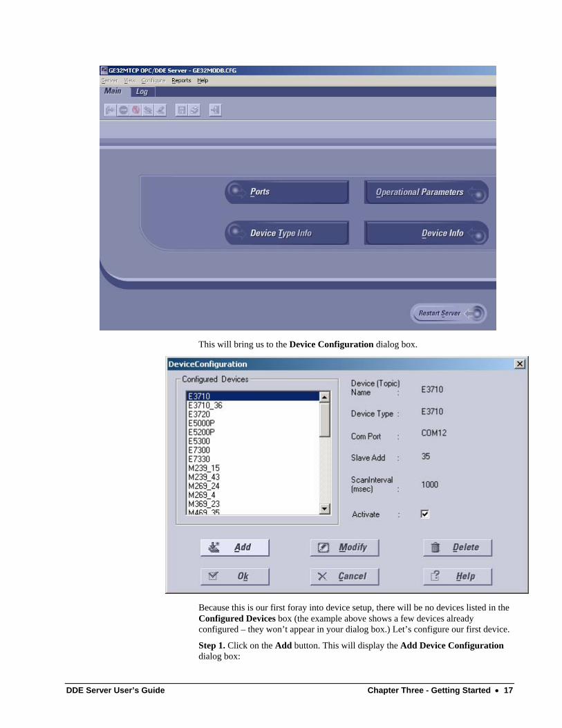
This will bring us to the Device Configuration dialog box.
Because this is our first foray into device setup, there will be no devices listed in the Configured Devices box (the example above shows a few devices already configured – they won’t appear in your dialog box.) Let’s configure our first device.
Step 1. Click on the Add button. This will display the Add Device Configuration dialog box:
DDE Server User’s Guide Chapter Three - Getting Started • 17
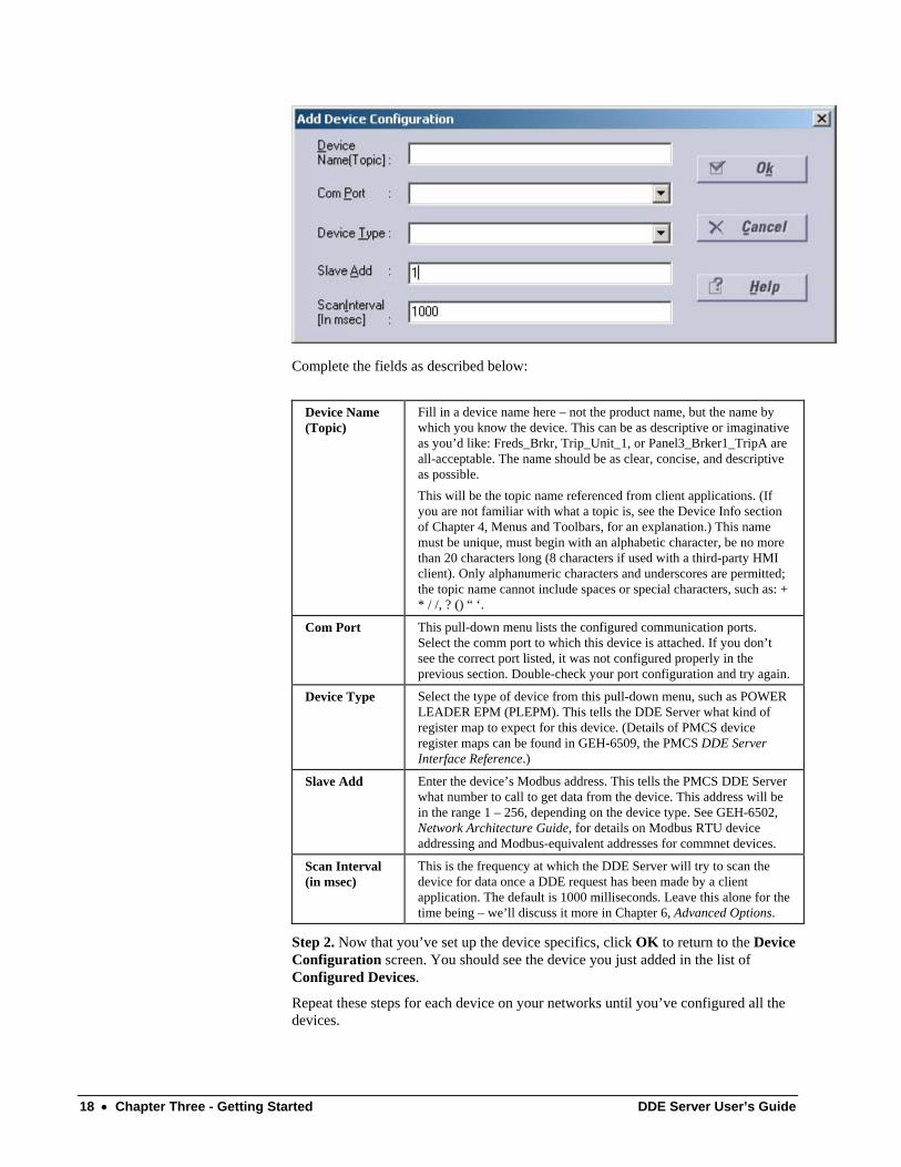
Complete the fields as described below:
Device Name (Topic)
Fill in a device name here – not the product name, but the name by which you know the device. This can be as descriptive or imaginative as you’d like: Freds_Brkr, Trip_Unit_1, or Panel3_Brker1_TripA are all-acceptable. The name should be as clear, concise, and descriptive as possible. This will be the topic name referenced from client applications. (If you are not familiar with what a topic is, see the Device Info section of Chapter 4, Menus and Toolbars, for an explanation.) This name must be unique, must begin with an alphabetic character, be no more than 20 characters long (8 characters if used with a third-party HMI client). Only alphanumeric characters and underscores are permitted; the topic name cannot include spaces or special characters, such as: + * / /, ? () “ ‘.
Com Port This pull-down menu lists the configured communication ports. Select the comm port to which this device is attached. If you don’t see the correct port listed, it was not configured properly in the previous section. Double-check your port configuration and try again.
Device Type Select the type of device from this pull-down menu, such as POWER LEADER EPM (PLEPM). This tells the DDE Server what kind of register map to expect for this device. (Details of PMCS device register maps can be found in GEH-6509, the PMCS DDE Server Interface Reference.)
Slave Add Enter the device’s Modbus address. This tells the PMCS DDE Server what number to call to get data from the device. This address will be in the range 1 – 256, depending on the device type. See GEH-6502, Network Architecture Guide, for details on Modbus RTU device addressing and Modbus-equivalent addresses for commnet devices.
Scan Interval (in msec)
This is the frequency at which the DDE Server will try to scan the device for data once a DDE request has been made by a client application. The default is 1000 milliseconds. Leave this alone for the time being – we’ll discuss it more in Chapter 6, Advanced Options.
Step 2. Now that you’ve set up the device specifics, click OK to return to the Device Configuration screen. You should see the device you just added in the list of Configured Devices.
Repeat these steps for each device on your networks until you’ve configured all the devices.
18 • Chapter Three - Getting Started DDE Server User’s Guide
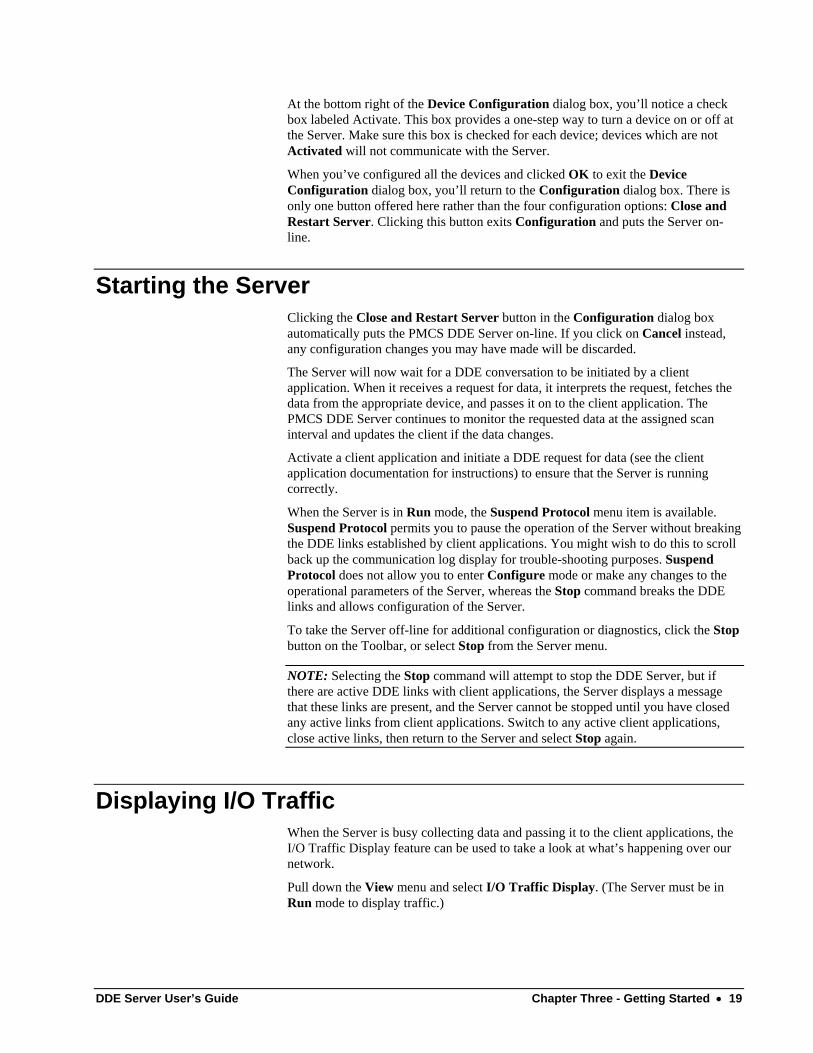
At the bottom right of the Device Configuration dialog box, you’ll notice a check box labeled Activate. This box provides a one-step way to turn a device on or off at the Server. Make sure this box is checked for each device; devices which are not Activated will not communicate with the Server.
When you’ve configured all the devices and clicked OK to exit the Device Configuration dialog box, you’ll return to the Configuration dialog box. There is only one button offered here rather than the four configuration options: Close and Restart Server. Clicking this button exits Configuration and puts the Server on-line.
Starting the Server Clicking the Close and Restart Server button in the Configuration dialog box automatically puts the PMCS DDE Server on-line. If you click on Cancel instead, any configuration changes you may have made will be discarded.
The Server will now wait for a DDE conversation to be initiated by a client application. When it receives a request for data, it interprets the request, fetches the data from the appropriate device, and passes it on to the client application. The PMCS DDE Server continues to monitor the requested data at the assigned scan interval and updates the client if the data changes.
Activate a client application and initiate a DDE request for data (see the client application documentation for instructions) to ensure that the Server is running correctly.
When the Server is in Run mode, the Suspend Protocol menu item is available. Suspend Protocol permits you to pause the operation of the Server without breaking the DDE links established by client applications. You might wish to do this to scroll back up the communication log display for trouble-shooting purposes. Suspend Protocol does not allow you to enter Configure mode or make any changes to the operational parameters of the Server, whereas the Stop command breaks the DDE links and allows configuration of the Server.
To take the Server off-line for additional configuration or diagnostics, click the Stop button on the Toolbar, or select Stop from the Server menu.
NOTE: Selecting the Stop command will attempt to stop the DDE Server, but if there are active DDE links with client applications, the Server displays a message that these links are present, and the Server cannot be stopped until you have closed any active links from client applications. Switch to any active client applications, close active links, then return to the Server and select Stop again.
Displaying I/O Traffic When the Server is busy collecting data and passing it to the client applications, the I/O Traffic Display feature can be used to take a look at what’s happening over our network.
Pull down the View menu and select I/O Traffic Display. (The Server must be in Run mode to display traffic.)
DDE Server User’s Guide Chapter Three - Getting Started • 19
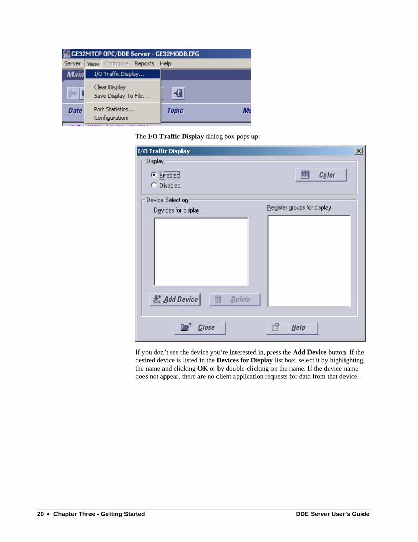
The I/O Traffic Display dialog box pops up:
If you don’t see the device you’re interested in, press the Add Device button. If the desired device is listed in the Devices for Display list box, select it by highlighting the name and clicking OK or by double-clicking on the name. If the device name does not appear, there are no client application requests for data from that device.
20 • Chapter Three - Getting Started DDE Server User’s Guide
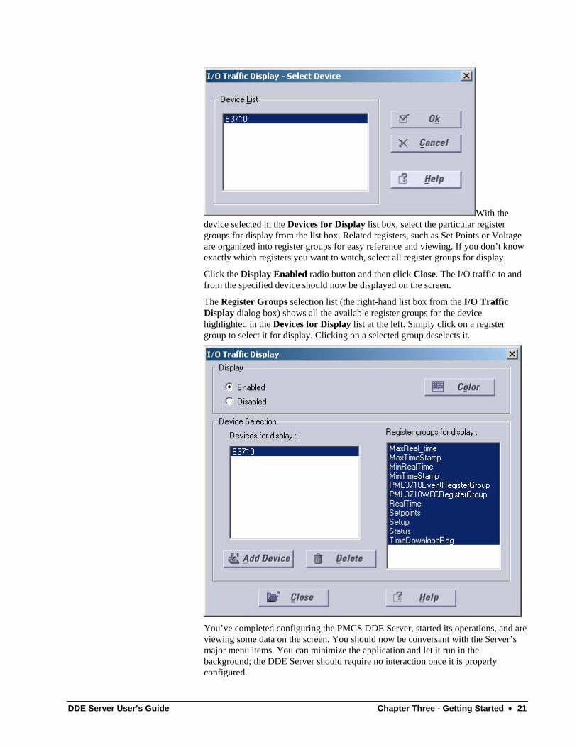
With the device selected in the Devices for Display list box, select the particular register groups for display from the list box. Related registers, such as Set Points or Voltage are organized into register groups for easy reference and viewing. If you don’t know exactly which registers you want to watch, select all register groups for display.
Click the Display Enabled radio button and then click Close. The I/O traffic to and from the specified device should now be displayed on the screen.
The Register Groups selection list (the right-hand list box from the I/O Traffic Display dialog box) shows all the available register groups for the device highlighted in the Devices for Display list at the left. Simply click on a register group to select it for display. Clicking on a selected group deselects it.
You’ve completed configuring the PMCS DDE Server, started its operations, and are viewing some data on the screen. You should now be conversant with the Server’s major menu items. You can minimize the application and let it run in the background; the DDE Server should require no interaction once it is properly configured.
DDE Server User’s Guide Chapter Three - Getting Started • 21

For more advanced use, study Chapter 4, Menus and Toolbars, which goes into detail on each menu and all available options.
22 • Chapter Three - Getting Started DDE Server User’s Guide

(This page left blank intentionally)
DDE Server User’s Guide Chapter Three - Getting Started • 23

Chapter Four - Menus and Toolbars
In this chapter, we’ll examine each menu and toolbar item in detail, describing its functions and options. As in Chapter 3, we’ll assume that some buttons (such as OK and Cancel) are self-evident and that you can interpret their functions from general experience with the Windows interface.
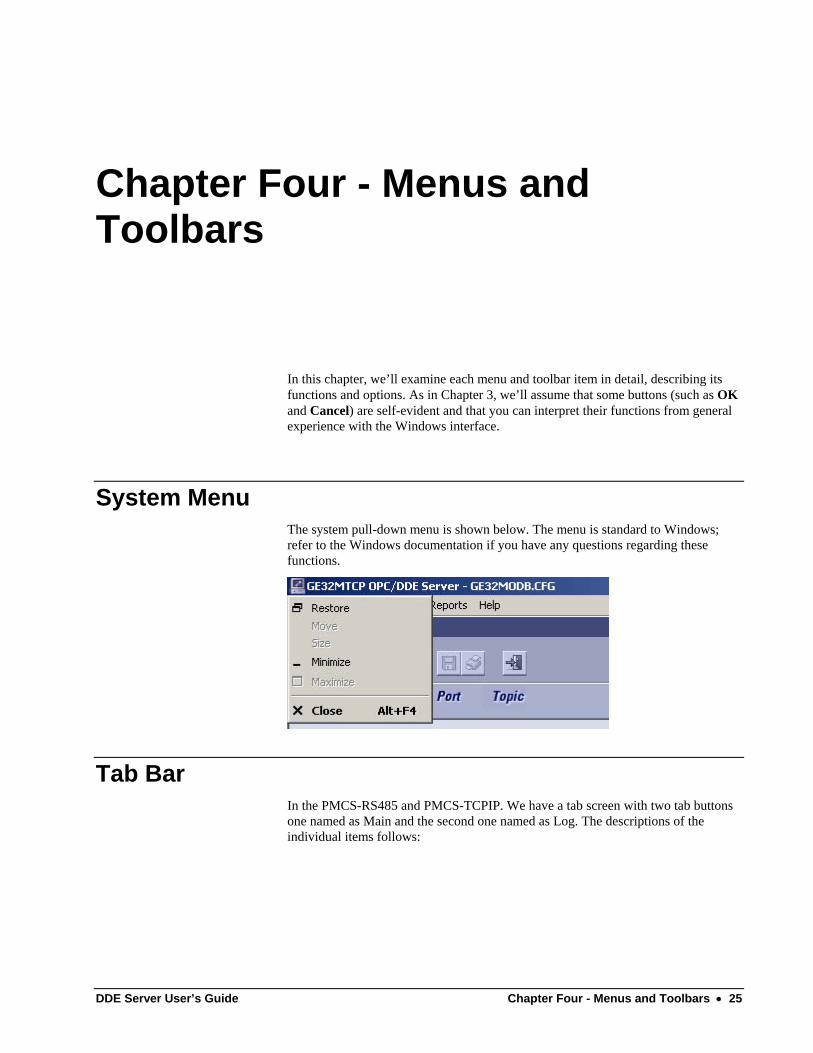
System Menu The system pull-down menu is shown below. The menu is standard to Windows; refer to the Windows documentation if you have any questions regarding these functions.
Tab Bar In the PMCS-RS485 and PMCS-TCPIP. We have a tab screen with two tab buttons one named as Main and the second one named as Log. The descriptions of the individual items follows:
DDE Server User’s Guide Chapter Four - Menus and Toolbars • 25
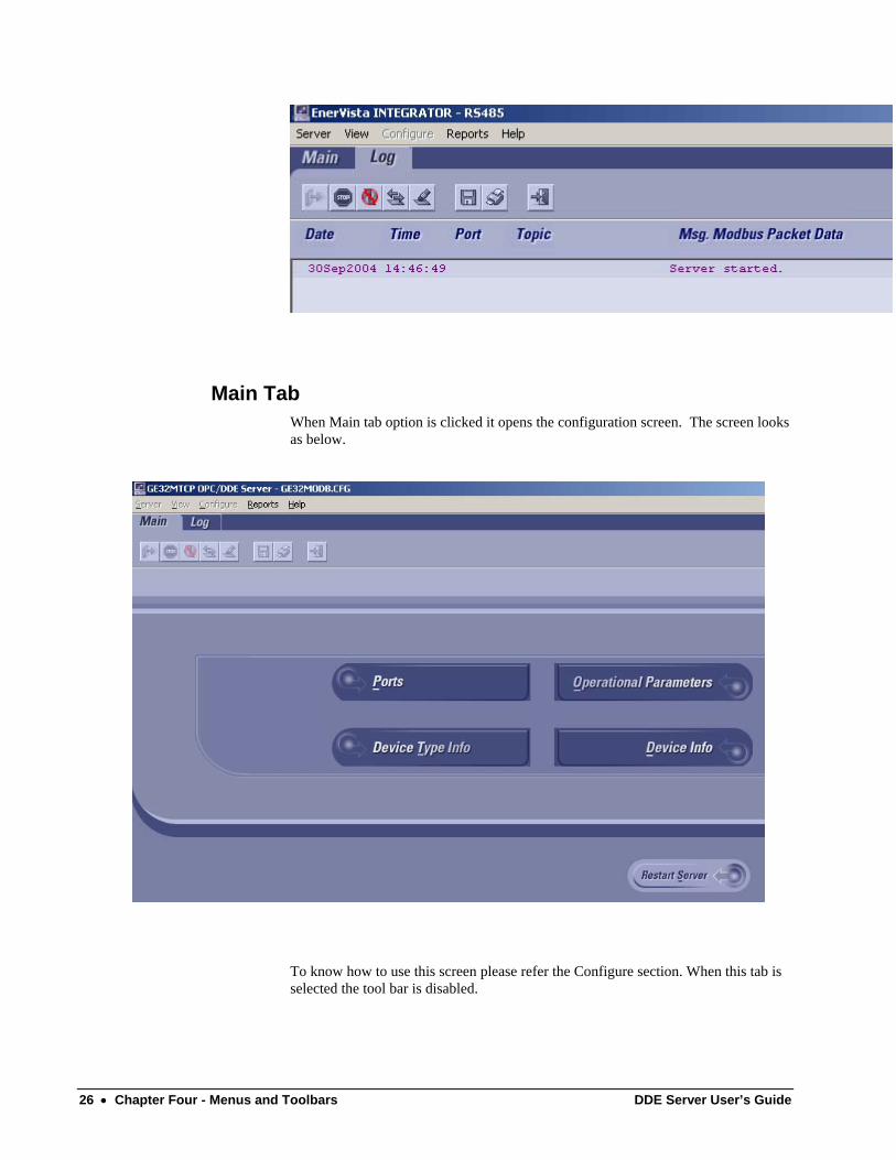
Main Tab When Main tab option is clicked it opens the configuration screen. The screen looks as below.
To know how to use this screen please refer the Configure section. When this tab is selected the tool bar is disabled.
26 • Chapter Four - Menus and Toolbars DDE Server User’s Guide
When the server is in start mode. We can restart the server by clicking on restart server in the above screen. When the server is in stop mode we have close option in the screen, which closes the main screen and opens in log mode.
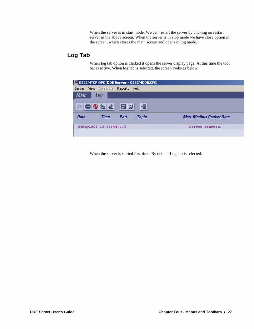
Log Tab When log tab option is clicked it opens the server display page. At this time the tool bar is active. When log tab is selected, the screen looks as below:
When the server is started first time. By default Log tab is selected.
DDE Server User’s Guide Chapter Four - Menus and Toolbars • 27
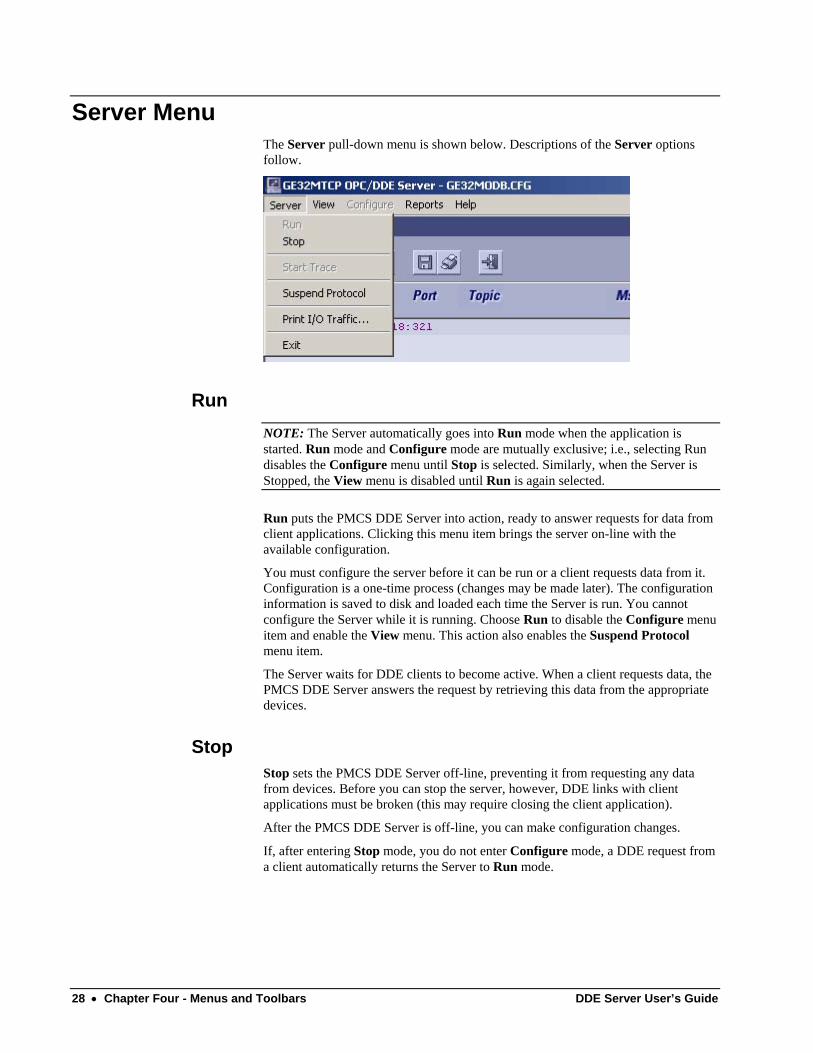
Server Menu The Server pull-down menu is shown below. Descriptions of the Server options follow.
Run NOTE: The Server automatically goes into Run mode when the application is started. Run mode and Configure mode are mutually exclusive; i.e., selecting Run disables the Configure menu until Stop is selected. Similarly, when the Server is Stopped, the View menu is disabled until Run is again selected.
Run puts the PMCS DDE Server into action, ready to answer requests for data from client applications. Clicking this menu item brings the server on-line with the available configuration.
You must configure the server before it can be run or a client requests data from it. Configuration is a one-time process (changes may be made later). The configuration information is saved to disk and loaded each time the Server is run. You cannot configure the Server while it is running. Choose Run to disable the Configure menu item and enable the View menu. This action also enables the Suspend Protocol menu item.
The Server waits for DDE clients to become active. When a client requests data, the PMCS DDE Server answers the request by retrieving this data from the appropriate devices.
Stop Stop sets the PMCS DDE Server off-line, preventing it from requesting any data from devices. Before you can stop the server, however, DDE links with client applications must be broken (this may require closing the client application).
After the PMCS DDE Server is off-line, you can make configuration changes.
If, after entering Stop mode, you do not enter Configure mode, a DDE request from a client automatically returns the Server to Run mode.
28 • Chapter Four - Menus and Toolbars DDE Server User’s Guide
Suspend Protocol/Resume Protocol This menu item is enabled when the Server starts running. Suspend Protocol and Resume Protocol are mutually exclusive options. One or the other is displayed on the Server menu, depending on the current state of the program.
Suspend Protocol temporarily halts the operation of the DDE Server without requiring that the links be broken, whereas Stop requires that the links be broken first. When you select Suspend, any DDE links remain intact; they merely become idle until you select Resume.
When you select Suspend Protocol, the Server stops data acquisition and the menu item changes to Resume Protocol. If the I/O Traffic display option is enabled, choosing this option stops data acquisition and display on the server screen.
When you select Resume Protocol, the suspended DDE links become active again and the Server resumes the process of answering requests for data.
Print I/O Traffic Print I/O Traffic sends the contents of the input/output traffic buffer to the default printer via the standard Windows Print dialog. You should Suspend the Server before printing or save to a file for later printing; while the Server is running, traffic may be passing so quickly that it will not print correctly.
Exit Exit is the standard Windows function for leaving the program.
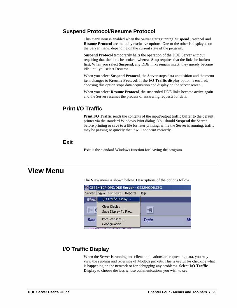
View Menu The View menu is shown below. Descriptions of the options follow.
I/O Traffic Display When the Server is running and client applications are requesting data, you may view the sending and receiving of Modbus packets. This is useful for checking what is happening on the network or for debugging any problems. Select I/O Traffic Display to choose devices whose communications you wish to see:
DDE Server User’s Guide Chapter Four - Menus and Toolbars • 29
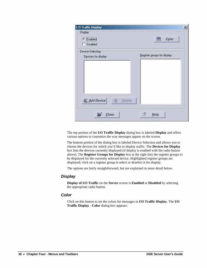
The top portion of the I/O Traffic Display dialog box is labeled Display and offers various options to customize the way messages appear on the screen.
The bottom portion of the dialog box is labeled Device Selection and allows you to choose the devices for which you’d like to display traffic. The Devices for Display box lists the devices currently displayed (if display is enabled with the radio button above). The Register Groups for Display box at the right lists the register groups to be displayed for the currently selected device. Highlighted register groups are displayed; click on a register group to select or deselect it for display.
The options are fairly straightforward, but are explained in more detail below.
Display Display of I/O Traffic on the Server screen is Enabled or Disabled by selecting the appropriate radio button.
Color Click on this button to set the colors for messages in I/O Traffic Display. The I/O Traffic Display - Color dialog box appears:
30 • Chapter Four - Menus and Toolbars DDE Server User’s Guide
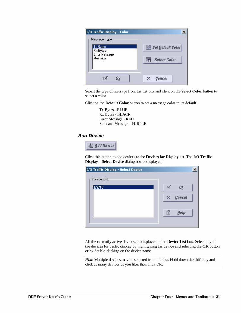
Select the type of message from the list box and click on the Select Color button to select a color.
Click on the Default Color button to set a message color to its default:
Tx Bytes - BLUE Rx Bytes - BLACK Error Message - RED Standard Message - PURPLE
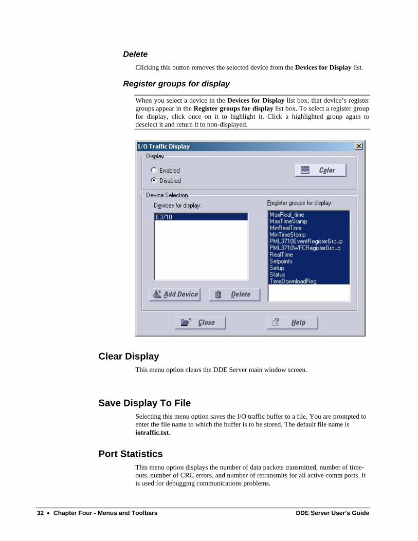
Add Device
Click this button to add devices to the Devices for Display list. The I/O Traffic Display – Select Device dialog box is displayed:
All the currently active devices are displayed in the Device List box. Select any of the devices for traffic display by highlighting the device and selecting the OK button or by double-clicking on the device name.
Hint: Multiple devices may be selected from this list. Hold down the shift key and click as many devices as you like, then click OK.
DDE Server User’s Guide Chapter Four - Menus and Toolbars • 31
Delete Clicking this button removes the selected device from the Devices for Display list.
Register groups for display
When you select a device in the Devices for Display list box, that device’s register groups appear in the Register groups for display list box. To select a register group for display, click once on it to highlight it. Click a highlighted group again to deselect it and return it to non-displayed.
Clear Display This menu option clears the DDE Server main window screen.
Save Display To File Selecting this menu option saves the I/O traffic buffer to a file. You are prompted to enter the file name to which the buffer is to be stored. The default file name is iotraffic.txt.
Port Statistics This menu option displays the number of data packets transmitted, number of time-outs, number of CRC errors, and number of retransmits for all active comm ports. It is used for debugging communications problems.
32 • Chapter Four - Menus and Toolbars DDE Server User’s Guide
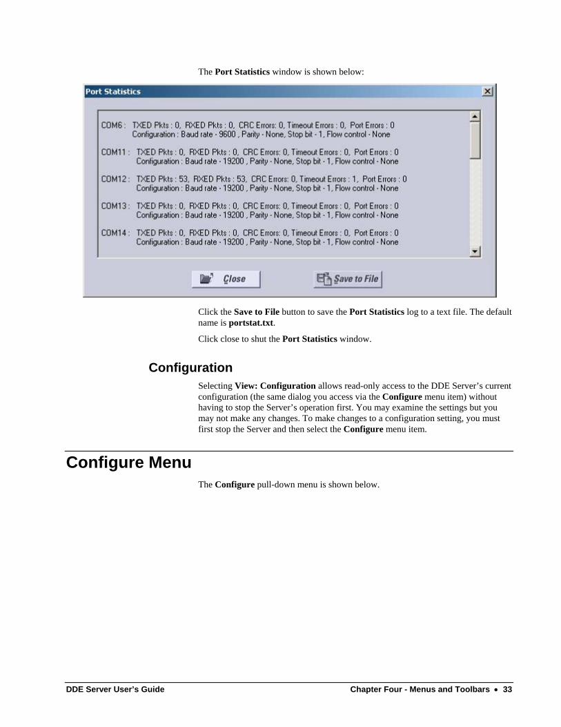
The Port Statistics window is shown below:
Click the Save to File button to save the Port Statistics log to a text file. The default name is portstat.txt.
Click close to shut the Port Statistics window.
Configuration Selecting View: Configuration allows read-only access to the DDE Server’s current configuration (the same dialog you access via the Configure menu item) without having to stop the Server’s operation first. You may examine the settings but you may not make any changes. To make changes to a configuration setting, you must first stop the Server and then select the Configure menu item.
Configure Menu The Configure pull-down menu is shown below.
DDE Server User’s Guide Chapter Four - Menus and Toolbars • 33
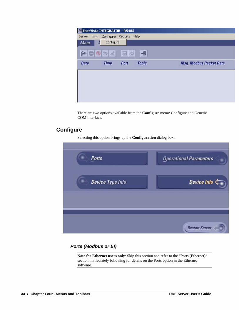
There are two options available from the Configure menu: Configure and Generic COM Interface.
Configure Selecting this option brings up the Configuration dialog box.
Ports (Modbus or EI)
Note for Ethernet users only: Skip this section and refer to the “Ports (Ethernet)” section immediately following for details on the Ports option in the Ethernet software.
34 • Chapter Four - Menus and Toolbars DDE Server User’s Guide
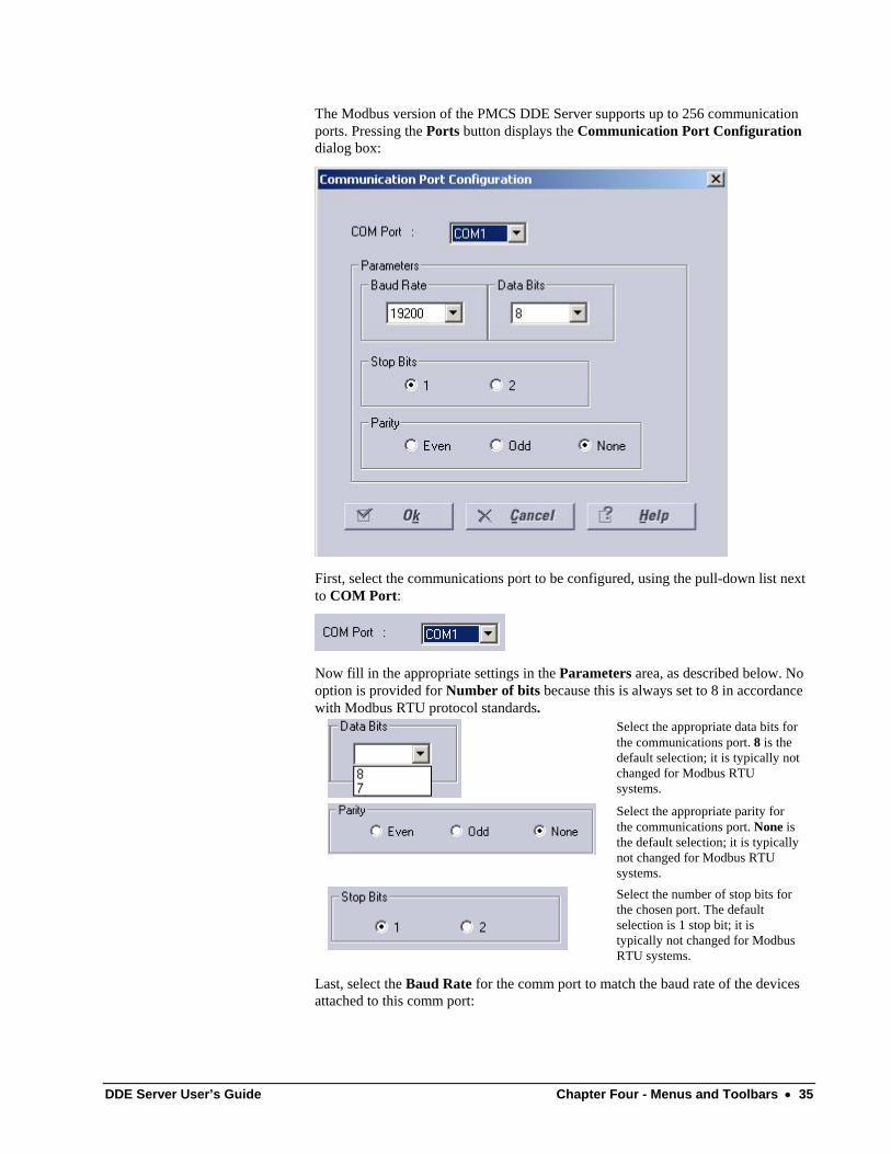
The Modbus version of the PMCS DDE Server supports up to 256 communication ports. Pressing the Ports button displays the Communication Port Configuration dialog box:
First, select the communications port to be configured, using the pull-down list next to COM Port:
Now fill in the appropriate settings in the Parameters area, as described below. No option is provided for Number of bits because this is always set to 8 in accordance with Modbus RTU protocol standards.
Select the appropriate data bits for the communications port. 8 is the default selection; it is typically not changed for Modbus RTU systems.
Select the appropriate parity for the communications port. None is the default selection; it is typically not changed for Modbus RTU systems.
Select the number of stop bits for the chosen port. The default selection is 1 stop bit; it is typically not changed for Modbus RTU systems.
Last, select the Baud Rate for the comm port to match the baud rate of the devices attached to this comm port:
DDE Server User’s Guide Chapter Four - Menus and Toolbars • 35
Click OK or Cancel to accept or reject the options selected.
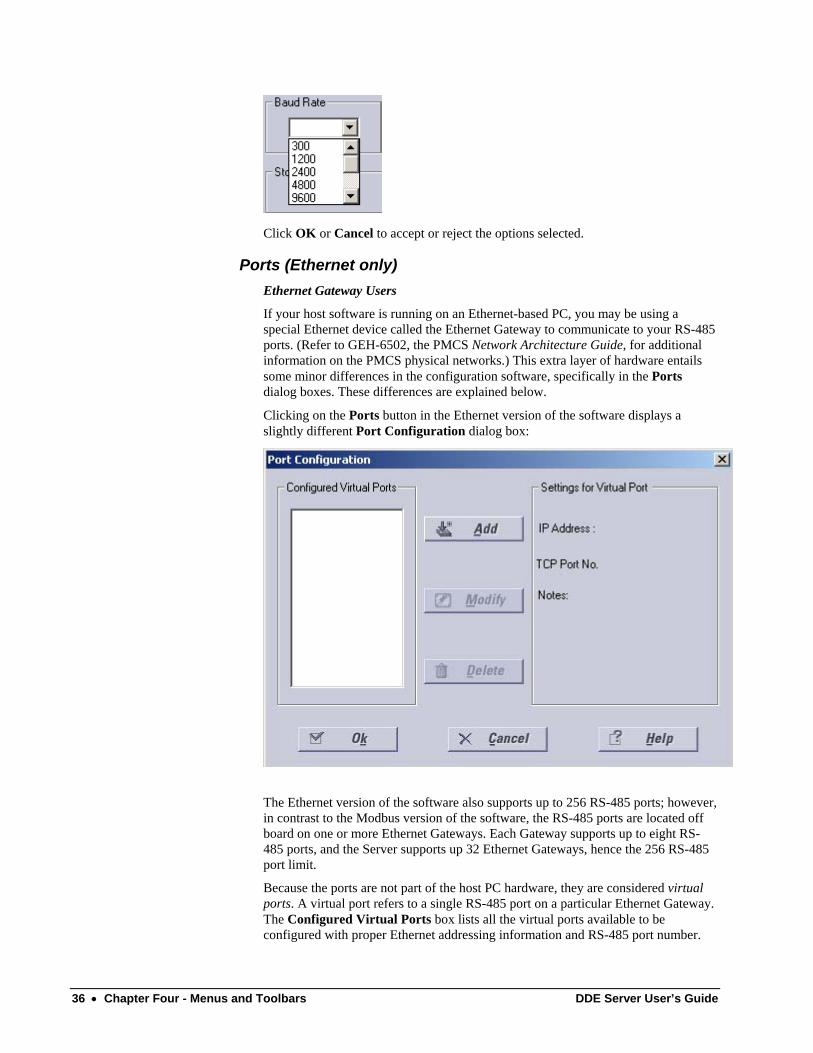
Ports (Ethernet only) Ethernet Gateway Users
If your host software is running on an Ethernet-based PC, you may be using a special Ethernet device called the Ethernet Gateway to communicate to your RS-485 ports. (Refer to GEH-6502, the PMCS Network Architecture Guide, for additional information on the PMCS physical networks.) This extra layer of hardware entails some minor differences in the configuration software, specifically in the Ports dialog boxes. These differences are explained below.
Clicking on the Ports button in the Ethernet version of the software displays a slightly different Port Configuration dialog box:
The Ethernet version of the software also supports up to 256 RS-485 ports; however, in contrast to the Modbus version of the software, the RS-485 ports are located off board on one or more Ethernet Gateways. Each Gateway supports up to eight RS-485 ports, and the Server supports up 32 Ethernet Gateways, hence the 256 RS-485 port limit.
Because the ports are not part of the host PC hardware, they are considered virtual ports. A virtual port refers to a single RS-485 port on a particular Ethernet Gateway. The Configured Virtual Ports box lists all the virtual ports available to be configured with proper Ethernet addressing information and RS-485 port number.
36 • Chapter Four - Menus and Toolbars DDE Server User’s Guide
The virtual ports are named NetCOM1 through NetCOM256; these names cannot be altered.
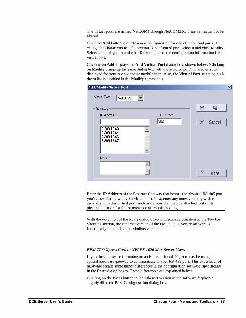
Click the Add button to create a new configuration for one of the virtual ports. To change the characteristics of a previously configured port, select it and click Modify. Select an existing port and click Delete to delete the configuration information for a virtual port.
Clicking on Add displays the Add Virtual Port dialog box, shown below. (Clicking on Modify brings up the same dialog box with the selected port’s characteristics displayed for your review and/or modification. Also, the Virtual Port selection pull-down list is disabled in the Modify command.)
Enter the IP Address of the Ethernet Gateway that houses the physical RS-485 port you’re associating with your virtual port. Last, enter any notes you may wish to associate with this virtual port, such as devices that may be attached to it or its physical location for future reference or troubleshooting.
With the exception of the Ports dialog boxes and some information in the Trouble-Shooting section, the Ethernet version of the PMCS DDE Server software is functionally identical to the Modbus version.
EPM 7700 Xpress Card or XPLEX 1620 Max Server Users
If your host software is running on an Ethernet-based PC, you may be using a special hardware gateway to communicate to your RS-485 ports This extra layer of hardware entails some minor differences in the configuration software, specifically in the Ports dialog boxes. These differences are explained below.
Clicking on the Ports button in the Ethernet version of the software displays a slightly different Port Configuration dialog box:
DDE Server User’s Guide Chapter Four - Menus and Toolbars • 37
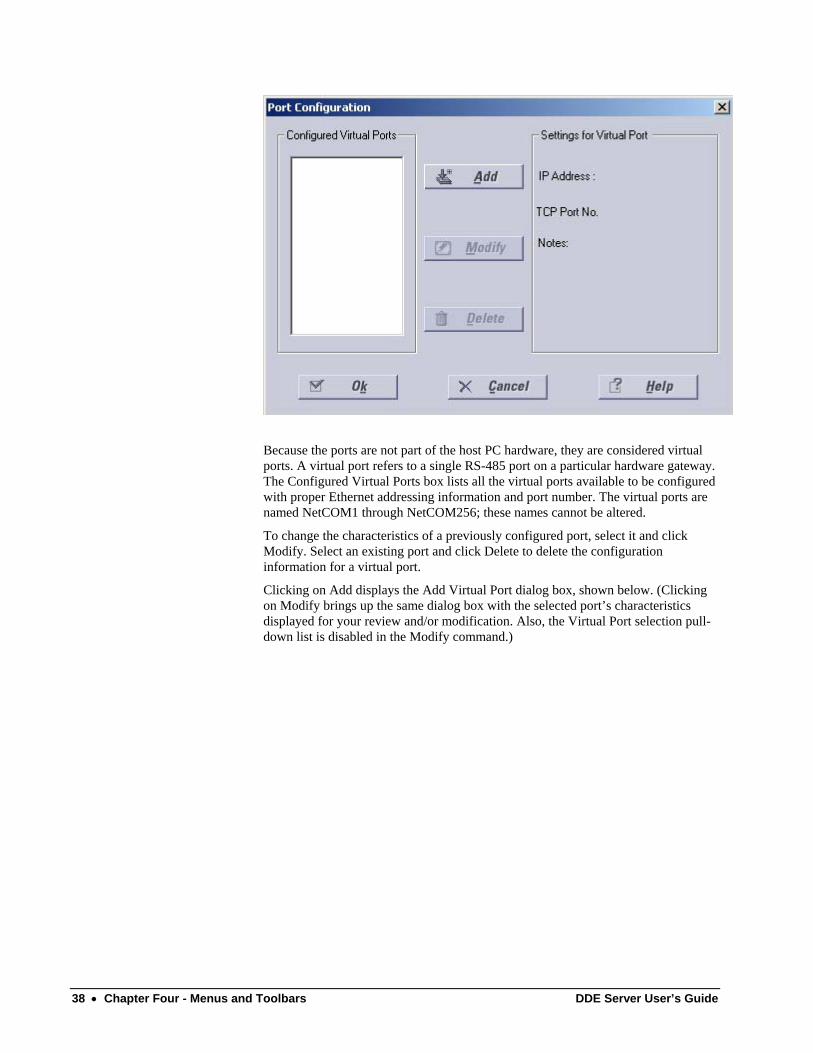
Because the ports are not part of the host PC hardware, they are considered virtual ports. A virtual port refers to a single RS-485 port on a particular hardware gateway. The Configured Virtual Ports box lists all the virtual ports available to be configured with proper Ethernet addressing information and port number. The virtual ports are named NetCOM1 through NetCOM256; these names cannot be altered.
To change the characteristics of a previously configured port, select it and click Modify. Select an existing port and click Delete to delete the configuration information for a virtual port.
Clicking on Add displays the Add Virtual Port dialog box, shown below. (Clicking on Modify brings up the same dialog box with the selected port’s characteristics displayed for your review and/or modification. Also, the Virtual Port selection pull-down list is disabled in the Modify command.)
38 • Chapter Four - Menus and Toolbars DDE Server User’s Guide
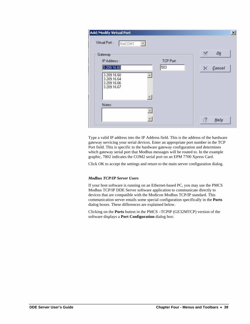
Type a valid IP address into the IP Address field. This is the address of the hardware gateway servicing your serial devices. Enter an appropriate port number in the TCP Port field. This is specific to the hardware gateway configuration and determines which gateway serial port that Modbus messages will be routed to. In the example graphic, 7802 indicates the COM2 serial port on an EPM 7700 Xpress Card.
Click OK to accept the settings and return to the main server configuration dialog.
Modbus TCP/IP Server Users
If your host software is running on an Ethernet-based PC, you may use the PMCS Modbus TCP/IP DDE Server software application to communicate directly to devices that are compatible with the Modicon Modbus TCP/IP standard. This communication server entails some special configuration specifically in the Ports dialog boxes. These differences are explained below.
Clicking on the Ports button in the PMCS –TCPIP (GE32MTCP) version of the software displays a Port Configuration dialog box:
DDE Server User’s Guide Chapter Four - Menus and Toolbars • 39
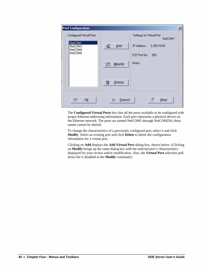
The Configured Virtual Ports box lists all the ports available to be configured with proper Ethernet addressing information. Each port represents a physical device on the Ethernet network. The ports are named NetCOM1 through NetCOM256; these names cannot be altered.
To change the characteristics of a previously configured port, select it and click Modify. Select an existing port and click Delete to delete the configuration information for a virtual port.
Clicking on Add displays the Add Virtual Port dialog box, shown below. (Clicking on Modify brings up the same dialog box with the selected port’s characteristics displayed for your review and/or modification. Also, the Virtual Port selection pull-down list is disabled in the Modify command.)
40 • Chapter Four - Menus and Toolbars DDE Server User’s Guide
Type a valid IP address into the IP Address field. This is the network address of the device to which you are assigning a port.
Click OK to accept the settings and return to the main server configuration dialog.
With the exception of the Ports dialog boxes and some information in the Trouble-Shooting section, this PMCS-TCPIP (GE32MTCP) version of the PMCS DDE Server software is functionally identical to the Modbus version.
Device Info Click this button to display the Device Configuration dialog box:
DDE Server User’s Guide Chapter Four - Menus and Toolbars • 41
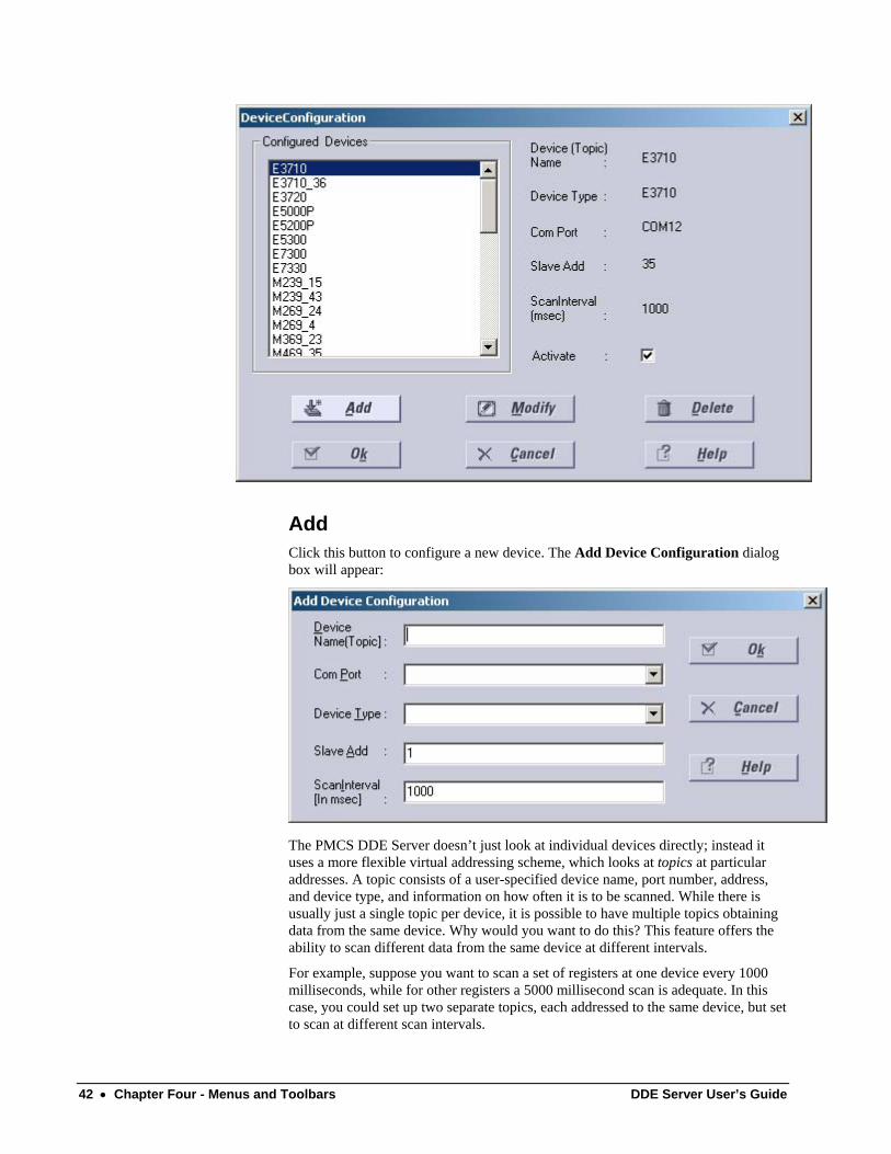
Add Click this button to configure a new device. The Add Device Configuration dialog box will appear:
The PMCS DDE Server doesn’t just look at individual devices directly; instead it uses a more flexible virtual addressing scheme, which looks at topics at particular addresses. A topic consists of a user-specified device name, port number, address, and device type, and information on how often it is to be scanned. While there is usually just a single topic per device, it is possible to have multiple topics obtaining data from the same device. Why would you want to do this? This feature offers the ability to scan different data from the same device at different intervals.
For example, suppose you want to scan a set of registers at one device every 1000 milliseconds, while for other registers a 5000 millisecond scan is adequate. In this case, you could set up two separate topics, each addressed to the same device, but set to scan at different scan intervals.
42 • Chapter Four - Menus and Toolbars DDE Server User’s Guide
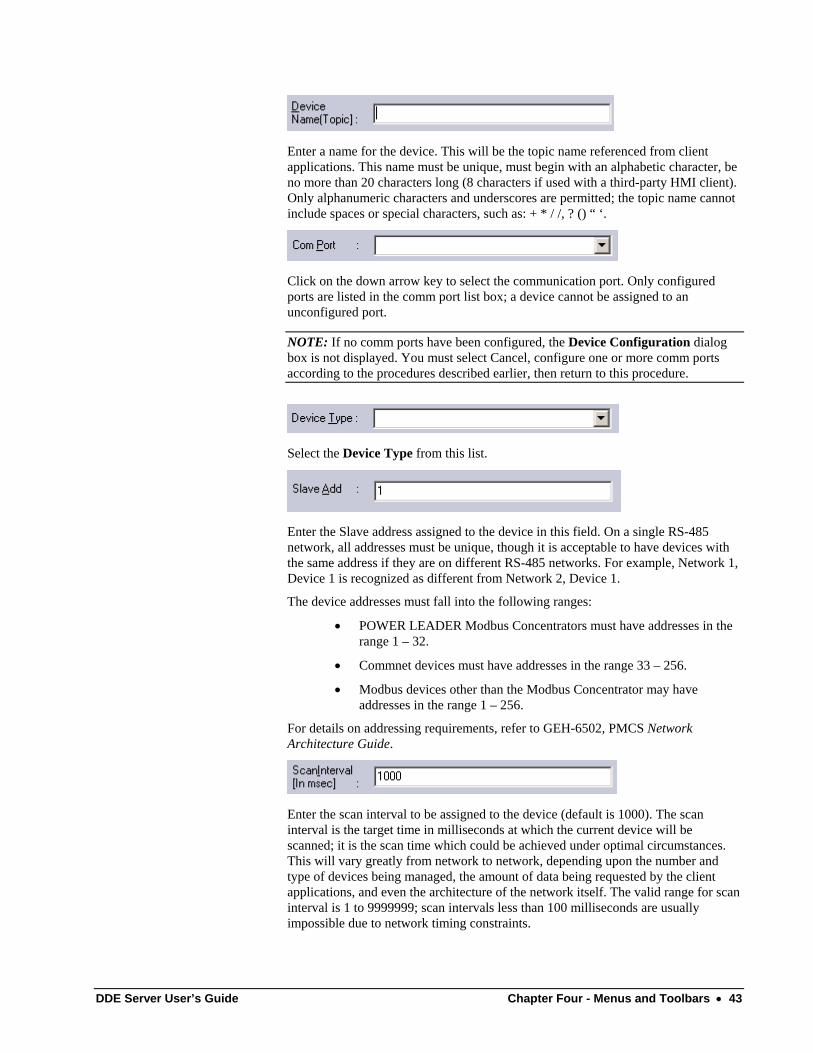
Enter a name for the device. This will be the topic name referenced from client applications. This name must be unique, must begin with an alphabetic character, be no more than 20 characters long (8 characters if used with a third-party HMI client). Only alphanumeric characters and underscores are permitted; the topic name cannot include spaces or special characters, such as: + * / /, ? () “ ‘.
Click on the down arrow key to select the communication port. Only configured ports are listed in the comm port list box; a device cannot be assigned to an unconfigured port.
NOTE: If no comm ports have been configured, the Device Configuration dialog box is not displayed. You must select Cancel, configure one or more comm ports according to the procedures described earlier, then return to this procedure.
Select the Device Type from this list.
Enter the Slave address assigned to the device in this field. On a single RS-485 network, all addresses must be unique, though it is acceptable to have devices with the same address if they are on different RS-485 networks. For example, Network 1, Device 1 is recognized as different from Network 2, Device 1.
The device addresses must fall into the following ranges:
• POWER LEADER Modbus Concentrators must have addresses in the range 1 – 32.
• Commnet devices must have addresses in the range 33 – 256.
• Modbus devices other than the Modbus Concentrator may have addresses in the range 1 – 256.
For details on addressing requirements, refer to GEH-6502, PMCS Network Architecture Guide.
Enter the scan interval to be assigned to the device (default is 1000). The scan interval is the target time in milliseconds at which the current device will be scanned; it is the scan time which could be achieved under optimal circumstances. This will vary greatly from network to network, depending upon the number and type of devices being managed, the amount of data being requested by the client applications, and even the architecture of the network itself. The valid range for scan interval is 1 to 9999999; scan intervals less than 100 milliseconds are usually impossible due to network timing constraints.
DDE Server User’s Guide Chapter Four - Menus and Toolbars • 43
Clicking OK accepts the entries and returns to the Device Configuration dialog box.
Modify Select the device (topic) to be modified and click the Modify button. The Modify Device Configuration dialog box will appear. The options and fields in this dialog box are similar to those in the Add Device Configuration dialog box. Make any necessary modifications and click on the OK button. The modified information is reflected in the Device Configuration dialog box.
Delete To delete a device (topic), select it and click on this button.
Activate checkbox At the bottom right of the Device Configuration dialog box, you’ll notice a check box labeled Activate. This box provides a one-step way to turn a device on or off at the Server. Make sure this box is checked for each device; devices which are not Activated will not communicate with the Server. Conversely, for troubleshooting purposes, you can use this checkbox to quickly take a device off-line.
Device Type Information CAUTION: Advanced users only. Do not access this option unless you have studied Chapter 6 and are sure of what you are doing. Misuse of this option may cause errors or malfunction of the Server.
See Chapter 6 of the GEH-6510 PMCS DDE Server User’s Guide for information on this option.
Operational Parameters CAUTION: Advanced users only. Do not access this option unless you have studied Chapter 6 and are sure of what you are doing. Misuse of this option may cause errors or malfunction of the Server.
See Chapter 6 of the User’s Guide, Advanced Options, for information on this option.
44 • Chapter Four - Menus and Toolbars DDE Server User’s Guide
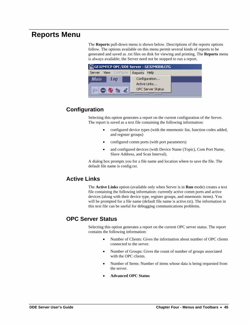
Reports Menu The Reports pull-down menu is shown below. Descriptions of the reports options follow. The options available on this menu permit several kinds of reports to be generated and saved as .txt files on disk for viewing and printing. The Reports menu is always available; the Server need not be stopped to run a report.
Configuration Selecting this option generates a report on the current configuration of the Server. The report is saved as a text file containing the following information:
• configured device types (with the mnemonic list, function codes added, and register groups)
• configured comm ports (with port parameters)
• and configured devices (with Device Name (Topic), Com Port Name, Slave Address, and Scan Interval).
A dialog box prompts you for a file name and location where to save the file. The default file name is config.txt.
Active Links The Active Links option (available only when Server is in Run mode) creates a text file containing the following information: currently active comm ports and active devices (along with their device type, register groups, and mnemonic items). You will be prompted for a file name (default file name is active.txt). The information in this text file can be useful for debugging communications problems.
OPC Server Status Selecting this option generates a report on the current OPC server status. The report contains the following information:
• Number of Clients: Gives the information about number of OPC clients connected to the server.
• Number of Groups: Gives the count of number of groups associated with the OPC clients.
• Number of Items: Number of items whose data is being requested from the server.
• Advanced OPC Status
DDE Server User’s Guide Chapter Four - Menus and Toolbars • 45
• Set Sample Period (ms): Here we can set the sample period for the items being requested. By default the value that is assigned is 1000.
• Number of read transactions performed per sample period.
• Number of write transactions performed per sample period.
• Number of change notifications performed per sample period.
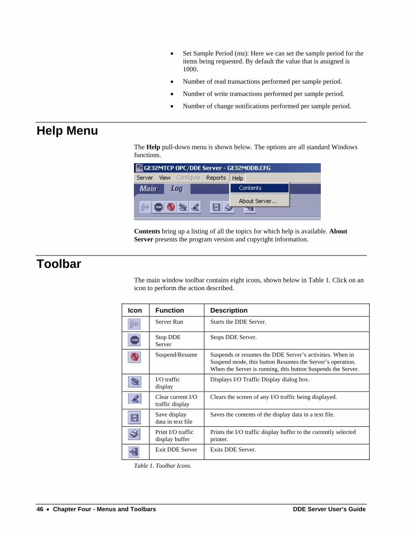
Help Menu The Help pull-down menu is shown below. The options are all standard Windows functions.
Contents bring up a listing of all the topics for which help is available. About Server presents the program version and copyright information.
Toolbar The main window toolbar contains eight icons, shown below in Table 1. Click on an icon to perform the action described.
Icon Function Description
Server Run Starts the DDE Server.
Stop DDE Server
Stops DDE Server.
Suspend/Resume Suspends or resumes the DDE Server’s activities. When in
Suspend mode, this button Resumes the Server’s operation. When the Server is running, this button Suspends the Server.
I/O traffic display
Displays I/O Traffic Display dialog box.
Clear current I/O traffic display
Clears the screen of any I/O traffic being displayed.
Save display data in text file
Saves the contents of the display data in a text file.
Print I/O traffic display buffer
Prints the I/O traffic display buffer to the currently selected printer.
Exit DDE Server Exits DDE Server.
Table 1. Toolbar Icons.
46 • Chapter Four - Menus and Toolbars DDE Server User’s Guide
Chapter Five - Troubleshooting
Trouble-Shooting the PMCS DDE Server This section provides you with some simple steps that can be taken to isolate and correct communication problems. The problems described here represent the most probable causes of communication failure.
NOTE: This is a general trouble-shooting guide – it does not cover every possible source of conflict. If you still cannot establish communications after reading this section, call the GE Resolution Center, at 1-800-547-8629.
WWLogger WWLogger is a software application that is included with the PMCS installation. It is installed in GE_PMCS \Server\ or GE_PMCS\GE32MTCP\ folders. The WWLogger application tracks all error messages generated by DDE communications or Server to device communications. Obviously this can be of tremendous value for trouble-shooting purposes. The messages tracked by WWLogger describe the application and topic or device that caused a given error. This information can then be used to diagnose and correct the cause of the error.
If you are experiencing trouble, launch WWLogger, and attempt to reproduce the error condition. You can then use the error messages displayed by WWLogger to troubleshoot your problem.
Error messages that may be encountered in the WWLogger are listed at the end of this chapter, in the section titled Error Messages.
DDE Server User’s Guide Chapter Five - Troubleshooting • 47
Communications – Client to Server This section explains the most common error situations that can occur when attempting to establish DDE conversations between client applications and the PMCS DDE Server.
When a client requires the status of a DDE item, it opens a link with the PMCS DDE Server and requests the data. The DDE Server collects the data from the device and returns it to the client application; it also begins monitoring the data and advises the client whenever the data item changes.
The DDE Server automatically handles all of the messages to and from the device. The client application simply tells the DDE Server what register, coil number, or I/O point to read or write. The DDE Server then automatically updates the client upon any change of that data value.
Always start the DDE Server before starting any client software. If a client attempts to establish a link with a Server that is not running, an error message will result.
When an error message is displayed, note the information shown in the error message. You can often determine the source of the error message from the message itself – usually an application that is not running or a topic that is not properly configured.
Below are several situations that will cause a DDE conversation error message to appear:
1. The DDE Server application is not running. You can verify this by opening the Windows Task List (press Shift+Ctrl+Esc keys) and checking the list of currently running applications for the Server.
2. The Server's program name is misspelled in the DDE Access Name definition. The Server is running, but its name is misspelled in one or more DDE Access Name definitions. The name entered in the DDE Access Name definition must be the DDE Server's actual program name (less the .exe extension) as seen in the Windows File Manager. If the name is misspelled, the Server will not be found.
3. The topic is not defined in the Server or it is misspelled. The Server may be functioning properly, but if a client requests data from a topic that doesn’t exist, an error is generated.
4. The mnemonic or register address is not defined in the Server or it is misspelled. The Server may be functioning properly, but if a client requests data from a mnemonic or register address that doesn’t exist, an error is generated.
Let’s assume that the Server’s name is spelled correctly in the client’s DDE request and that the Server is running. The client is now looking for a topic defined in the Server; for example, Device1. To check the topic name, close the client (the Server cannot be configured if the client is running) and open the Server’s program window. Invoke the Configure:Device Info... command. Is there a topic defined as Device1 listed in the dialog box? Is it spelled exactly (including spaces, etc.) as it is in the DDE Access Name definition?
NOTE: Make sure there are no blank spaces after the topic name in both the Server or in the DDE Access Name definition in the client.
48 • Chapter Five - Troubleshooting DDE Server User’s Guide
When you have checked all of the above, restart the client and switch to the Server’s program window. Make sure I/O Traffic Display is on; various messages should be appearing in the window. This indicates that the client and the Server are communicating.
If nothing appears in the Server’s window, try using WWLogger to track your error messages. The most probable error message indicates that the item used with one or more tagnames is unrecognized by the Server. Tagnames use specific naming conventions when accessing data from a Server, and deviation from these conventions can cause errors.
If a device you want data from is not available to any client software, make sure that any device you wish to see data from is Active. The Activate checkbox in the Server’s Device Configuration dialog box determines whether client software can see the device or not. Devices whose Activate checkbox is empty will not be available to client programs.
Communications – Server to Device This section addresses communications between the PMCS DDE Server and a device.
When attempting to establish communication, if no data appears in the client’s window, check the WWLogger for error messages. For example, one of the most common error messages is:
TIME-OUT COMn: DeviceName
This message indicates a problem between the Server and a device on comm port n named DeviceName. In most cases, either the Server is not communicating through the communication port or the device is not responding.
First, ensure that the RS-485 communication port configured for use with the topic matches the physical port the device is connected to. Second, check for other programs that may be accessing the port, such as other DDE Servers or terminal monitors. Shut down any such programs. Third, verify that the communication port is operating correctly in Windows. If the communications port is not operating correctly, the WWLogger may show a message “Unable to Open Port.”
To verify that the communication port is working properly in Windows, shut down the Server and start the Windows Terminal program. Configure the Terminal program to use the same communication port and settings (baud rate, parity, etc.). Use a null-modem cable to connect to another computer’s port running a Terminal program with the same settings. See if characters can be sent between the two computers. If you don’t have two computers but the computer you are using has another port available, connect the two communication ports, start two Terminal programs (each set to its own port) and try communicating between them. Alternatively, connect an external modem to the communication port in question and see if you can dial out with it.
NOTE: Remember, two devices cannot share interrupts (IRQs). Make sure the communication port you are using has a unique IRQ assigned.
If the communication port is working properly, look for problems on the device side. Potential problems in this area could be, but are not limited to, cabling, baud rate, parity, stop bits, faulty device communication port, and improper addressing of a Modbus Concentrator or Ethernet Gateway.
DDE Server User’s Guide Chapter Five - Troubleshooting • 49

If the device is an EPM 3710 or 3720, check to make sure the device is set to 32-bit mode, with invalid objects set to yes and password protection set to no. These settings must be made at the device itself.
If the problem is with a Multilin device, make sure the device is not in TEST mode. The PMCS DDE Server does not support TEST mode for any device, as a device in TEST mode will generate invalid data.
If you have completed all of these steps and are still unable to communicate with the device, call the GE Resolution Center at 1-800-547-8629.
Trouble-Shooting Flowchart The flowchart below may help you quickly isolate problems and direct you to solutions. If you work through the flowchart and still experience difficulty, refer to the Troubleshooting chart in the next section.
50 • Chapter Five - Troubleshooting DDE Server User’s Guide
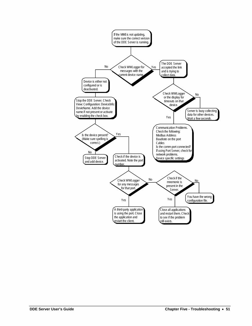
If the MMI is not updating,make sure the correct versionof the DDE Server is running.
Check WWLogger formessages with the
current device name.
Devic e is eit her notcon fig ure d o r i sdea cti vat ed.
Check WWLo gg er or the display for timeouts on th at
device . Serv er is busy collectingdata fo r o the r devices.Wait a fe w seconds.
No
Yes
Communication Prob lem s. Check the followin g: Modbus AddressBaudrate on the por t CablesIs the comm port co nne cte d? If using Port Server, ch eck for network problems. Device specific sett ings
The DDE Serve r accepted the lin k and is trying to collect data.
Stop th e D DE Ser ver. CheckView: Con figur atio n: DeviceInfo:Devi eNa me. Ad d t he devicename if not pre sent or activateby ena bli ng the c hec k box.
Is the de vic e p resent?(Mak e s ure spe lling is
cor re ct. )
No
Yes
Sto p D DE Se rverand a dd de vice.
Check if the device isactivated. Note the portnumber.
Check WWLoggerfor any messages
for that port.
No
Yes
A third-party applicationis using the port. Closethe application andrestart the client.
Check if the mnemonic is present in th e
Server .
No
You h ave t he wrongconfi gurat ion file.
Close all applicat ions and restart them . C hec k to see if the pro blem still exists.
Yes
YesNo
DDE Server User’s Guide Chapter Five - Troubleshooting • 51
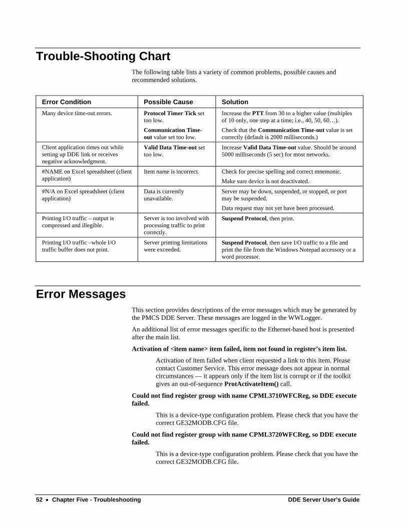
Trouble-Shooting Chart The following table lists a variety of common problems, possible causes and recommended solutions.
Error Condition Possible Cause Solution Many device time-out errors. Protocol Timer Tick set
too low. Communication Time-out value set too low.
Increase the PTT from 30 to a higher value (multiples of 10 only, one step at a time; i.e., 40, 50, 60…). Check that the Communication Time-out value is set correctly (default is 2000 milliseconds.)
Client application times out while setting up DDE link or receives negative acknowledgment.
Valid Data Time-out set too low.
Increase Valid Data Time-out value. Should be around 5000 milliseconds (5 sec) for most networks.
#NAME on Excel spreadsheet (client application)
Item name is incorrect. Check for precise spelling and correct mnemonic. Make sure device is not deactivated.
#N/A on Excel spreadsheet (client application)
Data is currently unavailable.
Server may be down, suspended, or stopped, or port may be suspended. Data request may not yet have been processed.
Printing I/O traffic – output is compressed and illegible.
Server is too involved with processing traffic to print correctly.
Suspend Protocol, then print.
Printing I/O traffic –whole I/O traffic buffer does not print.
Server printing limitations were exceeded.
Suspend Protocol, then save I/O traffic to a file and print the file from the Windows Notepad accessory or a word processor.
Error Messages This section provides descriptions of the error messages which may be generated by the PMCS DDE Server. These messages are logged in the WWLogger.
An additional list of error messages specific to the Ethernet-based host is presented after the main list.
Activation of <item name> item failed, item not found in register’s item list.
Activation of item failed when client requested a link to this item. Please contact Customer Service. This error message does not appear in normal circumstances — it appears only if the item list is corrupt or if the toolkit gives an out-of-sequence ProtActivateItem() call.
Could not find register group with name CPML3710WFCReg, so DDE execute failed.
This is a device-type configuration problem. Please check that you have the correct GE32MODB.CFG file.
Could not find register group with name CPML3720WFCReg, so DDE execute failed.
This is a device-type configuration problem. Please check that you have the correct GE32MODB.CFG file.
52 • Chapter Five - Troubleshooting DDE Server User’s Guide
Could not find register group with name CPML3720WFRReg, so DDE execute failed.
This is a device-type configuration problem. Please check that you have the correct GE32MODB.CFG file
Could not enable comm notification for <comm port>.
The Server could not initialize notification-based (interrupt-driven) communication for the communication port. Communication with the devices may not work well. Restart the Server. If the problem persists, check the communication port integrity.
Could not find register group with name PLMeterWFCRegisterGroup, so DDE execute failed
This is a device-type configuration problem. Check that you have the correct GE32MODB.CFG file.
Could not open RMS data file <file name>
The data file to store MicroVersaTrip device Peak Demand computation parameters could not be opened by the Server as defined in GE32MODB.INI. The .ini file entry may be wrong or the file may have been deleted.
Comport <comm port> is not configured, cannot close...
Server internal error. Please contact Customer Support. This error cannot occur if the Server is functioning properly. This error indicates corruption of the internal data structures.
COM<n> <device name> : Slave Address Error
The Server polled one Modbus address and got a response from some other address. This condition does not occur if all the devices on network are behaving correctly.
CPML3720WFCReg::OnRetrieveWFR Invalid BufferNo...
An incorrect buffer number was passed by the Waveform Client in the RetrieveWFR DDE Execute command. Please contact Customer Support.
CRC ERROR <comm port> : <device name>
The Server received a response from a slave with a CRC error. If there are frequent CRC errors, some possible causes are:
• Excess noise on the RS-485 network. Device responses are corrupted by noise.
• Some devices may require a certain idle time on the RS-485 network. If the Server’s protocol timer tick value is set too low, then such devices may give frequent CRC errors. For currently supported devices, timer tick values less than 30 milliseconds are not recommended.
CServerApp::OnDeleteDev - Invalid toolkit index
Internal error in the Server. Please contact Customer Service
DDE Execute <DDE execute command> failed
Possible causes are:
• The execute command is misspelled.
DDE Server User’s Guide Chapter Five - Troubleshooting • 53
• Parameters passed with the execute command are not proper. Refer to the Server interface specifications for correct parameter syntax and range.
• The execute command string has some extra space characters. The Server does not accept extra space characters in execute commands. Please follow the Server interface specifications strictly.
• The DDE execute command is not supported for the topic on which it was issued.
Device <device name> DEAD
The device is declared DEAD as a result of communication failure. This means the device has not responded to repeated queries in a certain time and the system assumes that there is some problem at the device keeping it from responding, that the device is dead for the moment. Dead devices are scanned occasionally to see if they have come back on-line.
Device <device name> ACTIVE
A previously DEAD device has resumed communications.
<device name> device got deleted – discarding packet
This is an informational message. A client application deleted a topic and the Server is deleting a scheduled communication packet.
Error allocating new topic (<topic>, <toolkit id>) => 0
The Server is unable to initiate a DDE transaction with the topic. The possible causes are :
• The topic is not configured on the Server. Configure the topic in the Server.
• The communication port associated with the topic could not be opened or initialized properly. In this case, the Server displays communication port-related error messages just preceding this error message in WWLogger.
• The device type of the topic is not configured. Configure the topic’s Generic Device Type in the Server.
Exception Response, Error Code = <exception code> : <exception code string>
A slave device returned an exception code to a request from the Server. Following are the common exceptions:
• Illegal Function — The function code sent by the Server is not supported by the slave device.
• Illegal Data Address — The data address requested by the Server is not supported by the slave device.
• Illegal Data Value — The data value sent by the Server for a Holding register or a Coil is not a proper value for the particular register.
• Slave Device Failure — A slave device has detected an internal failure.
• Failure in Associated Device — An external device connected to the slave device has failed and the data requested cannot be sent. The
54 • Chapter Five - Troubleshooting DDE Server User’s Guide
Server logs this error and continues with the next packet of data to the same device.
• Acknowledge — The slave device has accepted the request and is processing it, but will require a long time to do so. This response is returned by some of the slave devices to prevent a time-out error at the Server. The Server notes the device as “sleeping” and waits for its response, rather than requerying the device. The length of time (in milliseconds) the Server waits for the response is referred to as the elapsed retry time. This parameter is set in the Server’s .ini file. When the elapsed retry time has passed, the Server will resume sending packets to the device.
• Slave Device Busy — A slave device is busy processing internal computations. This message is similar to Acknowledge above. The Server marks the device as “sleeping” and will not transmit packets of data to the device until the elapsed retry time has passed.
• Negative Acknowledge — A slave device cannot perform the program function in the query. An example might be a circuit breaker in local-control mode when the Server attempts to exercise an on/off command. The device will not permit remote control to override local control and will reply a Negative Acknowledge.
• Memory Parity Error — The slave attempted to read extended memory but detected a parity error in the memory.
• Unknown Error Code — The slave device has returned an unknown error code. Check the slave device manual for explanations of device-specific exception codes.
Failed to activate item(<logical device handle>, <Protocol Handle>)=>0
Server internal error. Please contact Customer Support.
Failed to create item (<logical device handle>) (<toolkit handle>) (<item name>) =>0
Possible causes are :
• The item name is not spelled correctly on the client.
• The item register(s) is (are) not configured in any of the register groups of the device type. Check the device type’s register-group configuration.
• If the item name uses a mnemonic convention, then the mnemonic is not defined on the Server. Check the device type’s mnemonic configuration.
Failed to deactivate item(<logical device handle>, <Protocol Handle>)
Server internal error. Please contact Customer Support.
Failed to delete item(<logical device handle>, <Protocol Handle>)
Server internal error. Please contact Customer Support.
Initialization failed for <comm port>
The Server failed to open the communication port. Possible causes of this error are:
DDE Server User’s Guide Chapter Five - Troubleshooting • 55
• The communication port does not exist on the PC running the DDE Server. Reconfigure topics that are configured with this port to another port. This problem may be caused by improper configuration of the RS-485 card driver (if you are using some special multiport card). Please refer to the card driver’s configuration manual.
• The port is already being used by another application. Close any other applications on the machine and restart the Server.
• The port may not be working. Test the port with a communication program such as HyperTerminal.
No Write to Individual Discrete Bits
The client tried writing to individual bits of a read/write register, which is not allowed.
Open comm for <comm port> failed
This error may be followed by one of the following error messages:
• Invalid or unsupported ID <comm port> — The port is not supported or the port ID is bad. Check the ID of the port to which the devices are connected and reconfigure the topics with the correct port ID.
• Device already open <comm port> — Try restarting the Server. If the problem persists, the port may be in use by another application.
• Device not open <comm port> — Try restarting the Server.
• Unable to allocate queues — Try restarting the Server.
• Error in default parameters — The default parameters set for the port in the DDE Server configuration or other programs are bad.
• Hardware not present or already allocated <comm port> — Port hardware is not available. If there is a communication port-disabling facility (some notebook PCs have this facility to save power), enable the ports, reboot the machine, and try starting the Server again.
• Invalid byte size — The byte size is invalid.
• Unsupported baud rate — The baud rate that was programmed is not supported by the communication port. Please refer to the communication port hardware reference for supported baud rates.
• Unknown error from OpenComm: <error code> — Try restarting the Server.
RegFormat Name is INVALID
The register name(either as mnemonic equivalent or as item name) is not valid.
Retrieve command time not occurred <device name>
This error occurs when the Waveform client sends the RetrieveWFC command very soon after it has sent the TriggerWFC command. Introduce a small delay (approx. 5 seconds) before issuing the RetrieveWFC command to the Server. This will allow the device to collect waveform data properly.
RetrieveWFR : Got out of range values for depth, range is 1-3
56 • Chapter Five - Troubleshooting DDE Server User’s Guide
The Waveform Client has passed an out-of-range value for the PML3720 waveform recorder depth parameter. Valid values are 1, 2, or 3.
The device type <device type name> is NOT a valid type for topic
The Server detected an unconfigured device type for a topic being created. Possible reasons are :
• The <device type name> has been deleted from the device-type configuration file (GE32MODB.CFG). Reconfigure the device type that generated the error or, if you intend to remove all the devices of that particular type, go to device (topic) configuration and remove all the topics with this device type. NOTE: This applies to generic devices only.
• GE32MODB.INI entry DocFile points to an incorrect device-type configuration file. Enter the correct path to the configuration file.
TIME-OUT <comm port> : <device name>
The Server timed out for a query to the slave device. This can happen under various conditions :
• Topic configuration has the wrong port configured for the device.
• The slave address configured for the topic is not correct.
• The communication time-out value is set too low on the Server. Check the value set for ‘Communication time-out’ entry of the GE32MODB.INI file. Values less than 2000 milliseconds are not recommended.
• The port configuration for the device does not match the port configuration at the Server. (Wrong baud rate, wrong stop bits, wrong number of bits, wrong parity, etc.)
• The device and the Host PC are not connected properly. Check the RS-485 network connections.
• Excess noise on the RS-485 network. Devices may not be receiving Server query packets properly.
• Some devices may require a certain idle time on the RS-485 network. If the Server’s protocol timer tick value is set too low, then such devices may give frequent time-out errors. For currently supported devices on Server version 6.0xxx, timer tick values less than 65 milliseconds are not recommended.
Unable to free topic (hLogDev = <logical device handle>)
Internal error for the Server. Please contact Customer Support according to the information in the Read-This-Book-First.
Unable to open RMS data file for rewriting RMS data
The RMS data file has been deleted since the Server started. Restart the Server. The Server will create a new RMS data file during startup.
DDE Server User’s Guide Chapter Five - Troubleshooting • 57

(This page left blank intentionally)
58 • Chapter Five - Troubleshooting DDE Server User’s Guide
Chapter Six - Advanced Options
Warning CAUTION: For advanced users only!
These advanced options are for experts only! Do not attempt these actions if you are not sure of what you are doing; it is possible to render your PMCS DDE Server inoperable, forcing you to reinstall it and potentially lose your device configurations. Please read all instructions before attempting any advanced configuration.
The information contained in this section applies to two types of devices:
• the broadly-defined generic devices that must be completely defined by the user
• the highly flexible GE Fanuc PLC family of products.
The GE Fanuc PLC 90/70, PLC 90/30, and Micro90 PLC consist of a backplane to which may be attached a wide variety of modules with a broad range of functions, from metering and data collection to process control. Because these devices are so flexible and there is no way to predict the options that will be chosen by the end user, they must be configured in the same manner as a generic device.
Device Type Information – Adding Generic Devices The PMCS DDE Server is pre-configured to support the MULTILINTM family of power-management devices, as well as a variety of third-party devices. However, you may add additional kinds of devices by creating your own device type. These “generic” devices have the register maps and functions that you assign, as explained in this section. The generic device type does not support the use of the DDE Server’s special device handling, such as automatic time synchronization, waveform capability, or event handling.
The procedure for adding a generic device is as follows. The details of each option mentioned are provided after the procedure. Remember that the Server must be stopped before you can do any configuration.
Step 1. Select the Device Type Info option from the Configuration menu to display the Device Types dialog box, shown below.
Step 2. Enter the name for your new generic device in the field at the bottom of the dialog box. The field is labeled Enter Device Type Name. Click the Add Default Type button to add the new device type to the list of Configured Device Types.
DDE Server User’s Guide Chapter Six - Advanced Options • 59
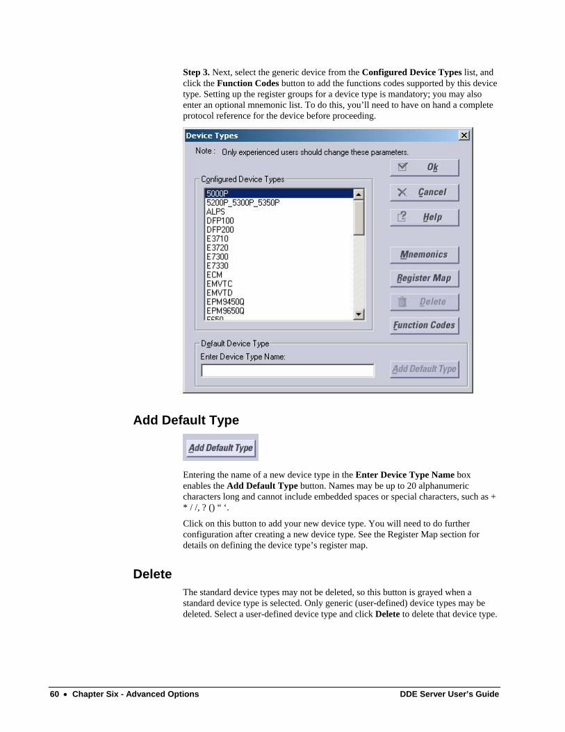
Step 3. Next, select the generic device from the Configured Device Types list, and click the Function Codes button to add the functions codes supported by this device type. Setting up the register groups for a device type is mandatory; you may also enter an optional mnemonic list. To do this, you’ll need to have on hand a complete protocol reference for the device before proceeding.
Add Default Type
Entering the name of a new device type in the Enter Device Type Name box enables the Add Default Type button. Names may be up to 20 alphanumeric characters long and cannot include embedded spaces or special characters, such as + * / /, ? () “ ‘.
Click on this button to add your new device type. You will need to do further configuration after creating a new device type. See the Register Map section for details on defining the device type’s register map.
Delete The standard device types may not be deleted, so this button is grayed when a standard device type is selected. Only generic (user-defined) device types may be deleted. Select a user-defined device type and click Delete to delete that device type.
60 • Chapter Six - Advanced Options DDE Server User’s Guide
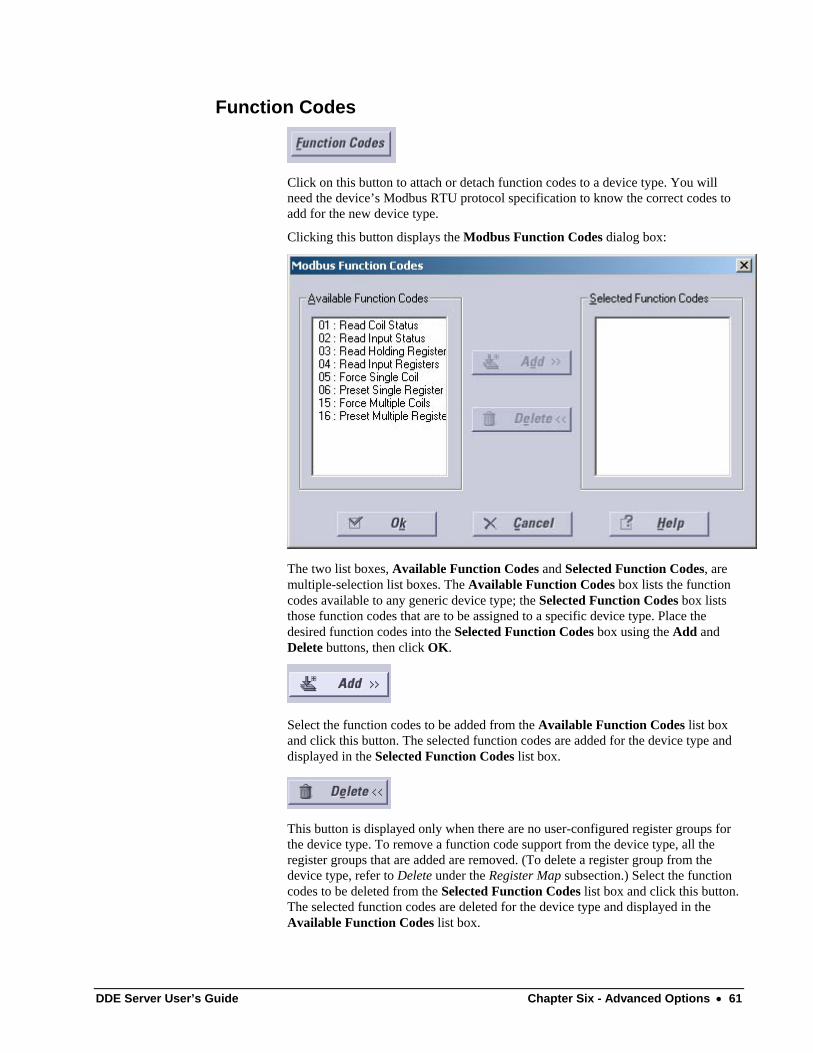
Function Codes
Click on this button to attach or detach function codes to a device type. You will need the device’s Modbus RTU protocol specification to know the correct codes to add for the new device type.
Clicking this button displays the Modbus Function Codes dialog box:
The two list boxes, Available Function Codes and Selected Function Codes, are multiple-selection list boxes. The Available Function Codes box lists the function codes available to any generic device type; the Selected Function Codes box lists those function codes that are to be assigned to a specific device type. Place the desired function codes into the Selected Function Codes box using the Add and Delete buttons, then click OK.
Select the function codes to be added from the Available Function Codes list box and click this button. The selected function codes are added for the device type and displayed in the Selected Function Codes list box.
This button is displayed only when there are no user-configured register groups for the device type. To remove a function code support from the device type, all the register groups that are added are removed. (To delete a register group from the device type, refer to Delete under the Register Map subsection.) Select the function codes to be deleted from the Selected Function Codes list box and click this button. The selected function codes are deleted for the device type and displayed in the Available Function Codes list box.
DDE Server User’s Guide Chapter Six - Advanced Options • 61
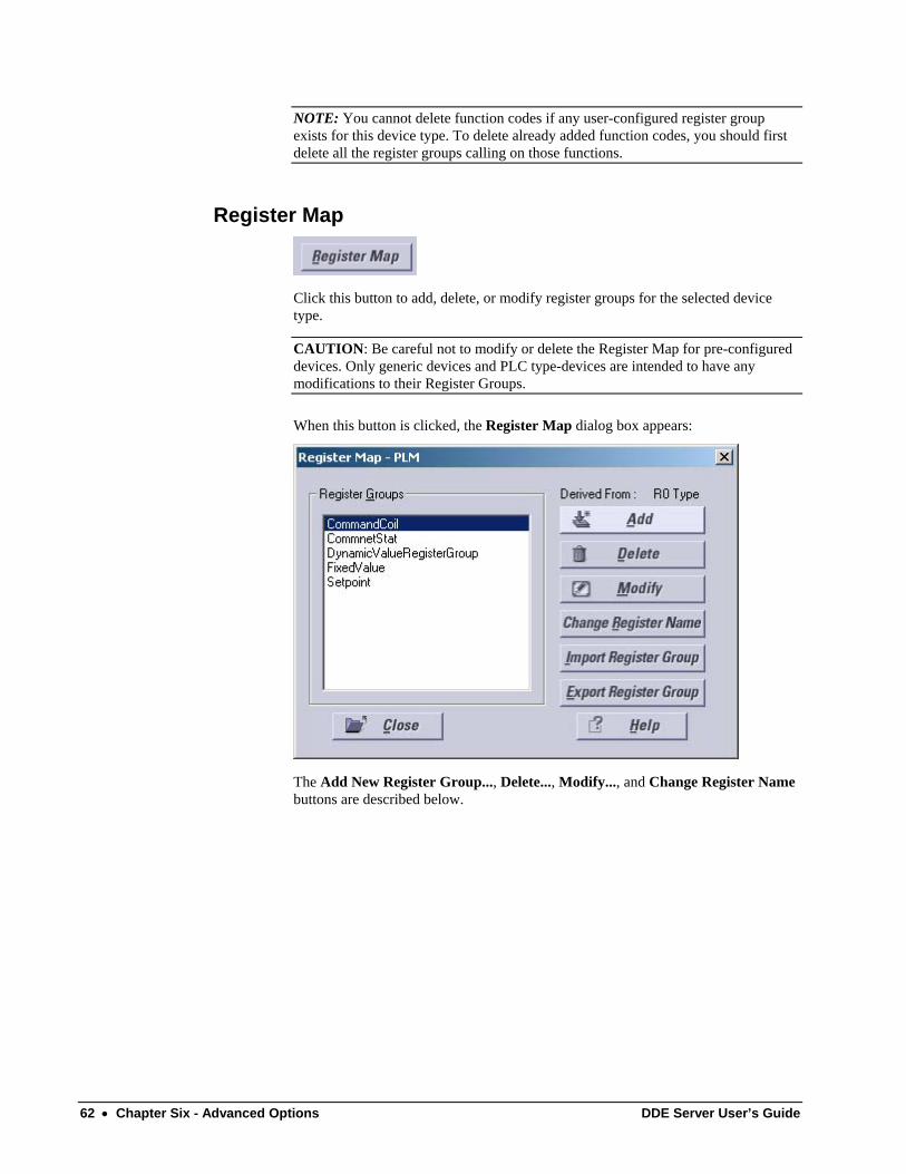
NOTE: You cannot delete function codes if any user-configured register group exists for this device type. To delete already added function codes, you should first delete all the register groups calling on those functions.
Register Map
Click this button to add, delete, or modify register groups for the selected device type.
CAUTION: Be careful not to modify or delete the Register Map for pre-configured devices. Only generic devices and PLC type-devices are intended to have any modifications to their Register Groups.
When this button is clicked, the Register Map dialog box appears:
The Add New Register Group..., Delete..., Modify..., and Change Register Name buttons are described below.
62 • Chapter Six - Advanced Options DDE Server User’s Guide
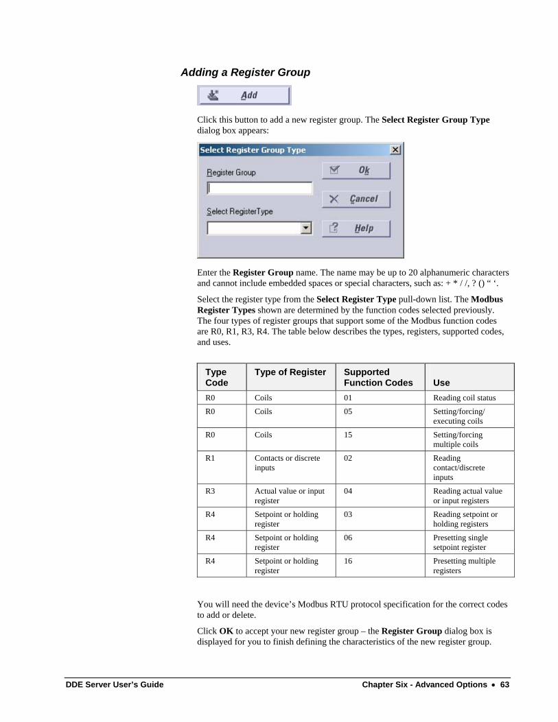
Adding a Register Group
Click this button to add a new register group. The Select Register Group Type dialog box appears:
Enter the Register Group name. The name may be up to 20 alphanumeric characters and cannot include embedded spaces or special characters, such as: + * / /, ? () “ ‘.
Select the register type from the Select Register Type pull-down list. The Modbus Register Types shown are determined by the function codes selected previously. The four types of register groups that support some of the Modbus function codes are R0, R1, R3, R4. The table below describes the types, registers, supported codes, and uses.
Type Code
Type of Register Supported Function Codes
Use
R0 Coils 01 Reading coil status
R0 Coils 05 Setting/forcing/ executing coils
R0 Coils 15 Setting/forcing multiple coils
R1 Contacts or discrete inputs
02 Reading contact/discrete inputs
R3 Actual value or input register
04 Reading actual value or input registers
R4 Setpoint or holding register
03 Reading setpoint or holding registers
R4 Setpoint or holding register
06 Presetting single setpoint register
R4 Setpoint or holding register
16 Presetting multiple registers
You will need the device’s Modbus RTU protocol specification for the correct codes to add or delete.
Click OK to accept your new register group – the Register Group dialog box is displayed for you to finish defining the characteristics of the new register group.
DDE Server User’s Guide Chapter Six - Advanced Options • 63
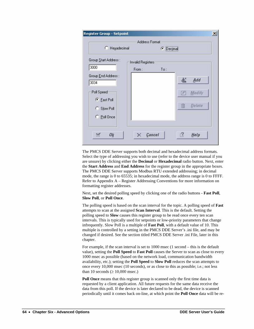
The PMCS DDE Server supports both decimal and hexadecimal address formats. Select the type of addressing you wish to use (refer to the device user manual if you are unsure) by clicking either the Decimal or Hexadecimal radio button. Next, enter the Start Address and End Address for the register group in the appropriate boxes. The PMCS DDE Server supports Modbus RTU extended addressing; in decimal mode, the range is 0 to 65535; in hexadecimal mode, the address range is 0 to FFFF. Refer to Appendix A – Register Addressing Conventions for more information on formatting register addresses.
Next, set the desired polling speed by clicking one of the radio buttons - Fast Poll, Slow Poll, or Poll Once.
The polling speed is based on the scan interval for the topic. A polling speed of Fast attempts to scan at the assigned Scan Interval. This is the default. Setting the polling speed to Slow causes this register group to be read once every ten scan intervals. This is typically used for setpoints or low-priority parameters that change infrequently. Slow Poll is a multiple of Fast Poll, with a default value of 10. This multiple is controlled by a setting in the PMCS DDE Server’s .ini file, and may be changed if desired. See the section titled PMCS DDE Server .ini File, later in this chapter.
For example, if the scan interval is set to 1000 msec (1 second – this is the default value), setting the Poll Speed to Fast Poll causes the Server to scan as close to every 1000 msec as possible (based on the network load, communication bandwidth availability, etc.); setting the Poll Speed to Slow Poll reduces the scan attempts to once every 10,000 msec (10 seconds), or as close to this as possible; i.e.; not less than 10 seconds (≥ 10,000 msec.)
Poll Once means that this register group is scanned only the first time data is requested by a client application. All future requests for the same data receive the data from this poll. If the device is later declared to be dead, the device is scanned periodically until it comes back on-line, at which point the Poll Once data will be re-
64 • Chapter Six - Advanced Options DDE Server User’s Guide
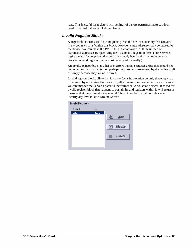
read. This is useful for registers with settings of a more permanent nature, which need to be read but are unlikely to change.
Invalid Register Blocks A register block consists of a contiguous piece of a device’s memory that contains many points of data. Within this block, however, some addresses may be unused by the device. We can make the PMCS DDE Server aware of these unused or extraneous addresses by specifying them as invalid register blocks. (The Server’s register maps for supported devices have already been optimized; only generic devices’ invalid register blocks must be entered manually.)
An invalid register block is a list of registers within a register group that should not be polled for data by the Server, perhaps because they are unused by the device itself or simply because they are not desired.
Invalid register blocks allow the Server to focus its attention on only those registers of interest; by not asking the Server to poll addresses that contain no data of interest, we can improve the Server’s potential performance. Also, some devices, if asked for a valid register block that happens to contain invalid registers within it, will return a message that the entire block is invalid. Thus, it can be of vital importance to identify any invalid blocks to the Server.
DDE Server User’s Guide Chapter Six - Advanced Options • 65
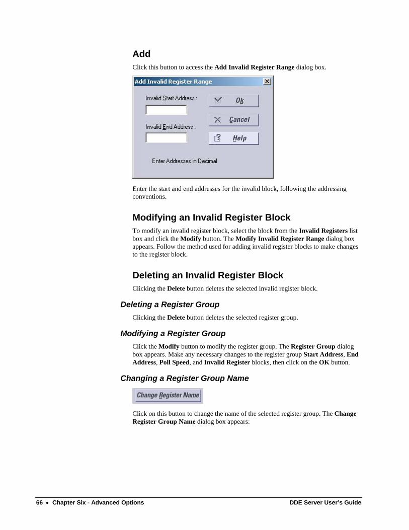
Add Click this button to access the Add Invalid Register Range dialog box.
Enter the start and end addresses for the invalid block, following the addressing conventions.
Modifying an Invalid Register Block To modify an invalid register block, select the block from the Invalid Registers list box and click the Modify button. The Modify Invalid Register Range dialog box appears. Follow the method used for adding invalid register blocks to make changes to the register block.
Deleting an Invalid Register Block Clicking the Delete button deletes the selected invalid register block.
Deleting a Register Group Clicking the Delete button deletes the selected register group.
Modifying a Register Group Click the Modify button to modify the register group. The Register Group dialog box appears. Make any necessary changes to the register group Start Address, End Address, Poll Speed, and Invalid Register blocks, then click on the OK button.
Changing a Register Group Name
Click on this button to change the name of the selected register group. The Change Register Group Name dialog box appears:
66 • Chapter Six - Advanced Options DDE Server User’s Guide
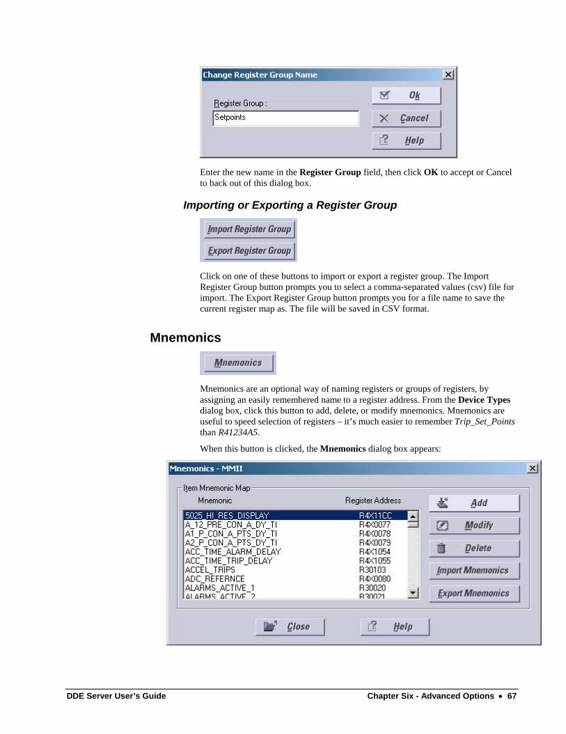
Enter the new name in the Register Group field, then click OK to accept or Cancel to back out of this dialog box.
Importing or Exporting a Register Group
Click on one of these buttons to import or export a register group. The Import Register Group button prompts you to select a comma-separated values (csv) file for import. The Export Register Group button prompts you for a file name to save the current register map as. The file will be saved in CSV format.
Mnemonics
Mnemonics are an optional way of naming registers or groups of registers, by assigning an easily remembered name to a register address. From the Device Types dialog box, click this button to add, delete, or modify mnemonics. Mnemonics are useful to speed selection of registers – it’s much easier to remember Trip_Set_Points than R41234A5.
When this button is clicked, the Mnemonics dialog box appears:
DDE Server User’s Guide Chapter Six - Advanced Options • 67
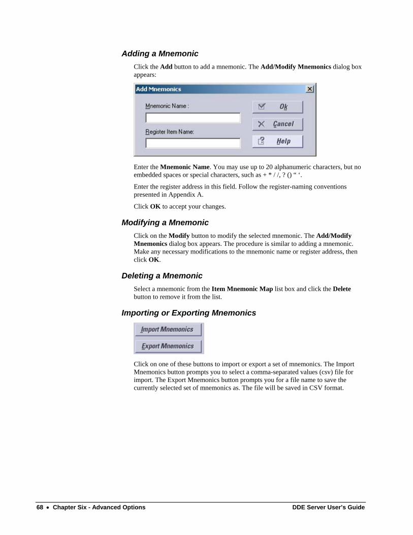
Adding a Mnemonic Click the Add button to add a mnemonic. The Add/Modify Mnemonics dialog box appears:
Enter the Mnemonic Name. You may use up to 20 alphanumeric characters, but no embedded spaces or special characters, such as + * / /, ? () “ ‘.
Enter the register address in this field. Follow the register-naming conventions presented in Appendix A.
Click OK to accept your changes.
Modifying a Mnemonic Click on the Modify button to modify the selected mnemonic. The Add/Modify Mnemonics dialog box appears. The procedure is similar to adding a mnemonic. Make any necessary modifications to the mnemonic name or register address, then click OK.
Deleting a Mnemonic Select a mnemonic from the Item Mnemonic Map list box and click the Delete button to remove it from the list.
Importing or Exporting Mnemonics
Click on one of these buttons to import or export a set of mnemonics. The Import Mnemonics button prompts you to select a comma-separated values (csv) file for import. The Export Mnemonics button prompts you for a file name to save the currently selected set of mnemonics as. The file will be saved in CSV format.
68 • Chapter Six - Advanced Options DDE Server User’s Guide
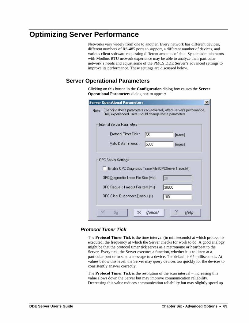
Optimizing Server Performance Networks vary widely from one to another. Every network has different devices, different numbers of RS-485 ports to support, a different number of devices, and various client software requesting different amounts of data. System administrators with Modbus RTU network experience may be able to analyze their particular network’s needs and adjust some of the PMCS DDE Server’s advanced settings to improve its performance. These settings are discussed below.
Server Operational Parameters Clicking on this button in the Configuration dialog box causes the Server Operational Parameters dialog box to appear:
Protocol Timer Tick The Protocol Timer Tick is the time interval (in milliseconds) at which protocol is executed; the frequency at which the Server checks for work to do. A good analogy might be that the protocol timer tick serves as a metronome or heartbeat to the Server. Every tick, the Server executes a function, whether it is to listen at a particular port or to send a message to a device. The default is 65 milliseconds. At values below this level, the Server may query devices too quickly for the devices to consistently answer correctly.
The Protocol Timer Tick is the resolution of the scan interval – increasing this value slows down the Server but may improve communication reliability. Decreasing this value reduces communication reliability but may slightly speed up
DDE Server User’s Guide Chapter Six - Advanced Options • 69
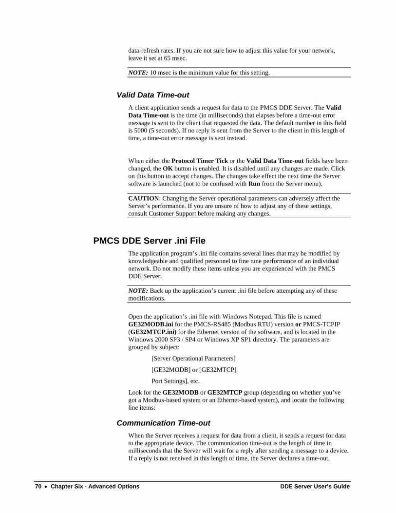
data-refresh rates. If you are not sure how to adjust this value for your network, leave it set at 65 msec.
NOTE: 10 msec is the minimum value for this setting.
Valid Data Time-out A client application sends a request for data to the PMCS DDE Server. The Valid Data Time-out is the time (in milliseconds) that elapses before a time-out error message is sent to the client that requested the data. The default number in this field is 5000 (5 seconds). If no reply is sent from the Server to the client in this length of time, a time-out error message is sent instead.
When either the Protocol Timer Tick or the Valid Data Time-out fields have been changed, the OK button is enabled. It is disabled until any changes are made. Click on this button to accept changes. The changes take effect the next time the Server software is launched (not to be confused with Run from the Server menu).
CAUTION: Changing the Server operational parameters can adversely affect the Server’s performance. If you are unsure of how to adjust any of these settings, consult Customer Support before making any changes.
PMCS DDE Server .ini File The application program’s .ini file contains several lines that may be modified by knowledgeable and qualified personnel to fine tune performance of an individual network. Do not modify these items unless you are experienced with the PMCS DDE Server.
NOTE: Back up the application’s current .ini file before attempting any of these modifications.
Open the application’s .ini file with Windows Notepad. This file is named GE32MODB.ini for the PMCS-RS485 (Modbus RTU) version or PMCS-TCPIP (GE32MTCP.ini) for the Ethernet version of the software, and is located in the Windows 2000 SP3 / SP4 or Windows XP SP1 directory. The parameters are grouped by subject:
[Server Operational Parameters]
[GE32MODB] or [GE32MTCP]
Port Settings], etc.
Look for the GE32MODB or GE32MTCP group (depending on whether you’ve got a Modbus-based system or an Ethernet-based system), and locate the following line items:
Communication Time-out When the Server receives a request for data from a client, it sends a request for data to the appropriate device. The communication time-out is the length of time in milliseconds that the Server will wait for a reply after sending a message to a device. If a reply is not received in this length of time, the Server declares a time-out.
70 • Chapter Six - Advanced Options DDE Server User’s Guide
The default Communication Time-out value is 2000 milliseconds.
Increasing this number may improve communication reliability, but will decrease performance.
Slow Poll Count The Slow Poll Count is a multiplier, with a default value of 10. The Slow Poll Count multiplied by the scan interval for a topic equals the scan interval for a register block if slow poll has been selected.
Increasing the Slow Poll Count value causes the Sever to scan slow-poll data less often, allowing more time to be devoted to scanning fast-poll registers. Decreasing this value requires the slow-poll register groups to be scanned more often, reducing the performance of fast-poll scanning.
Maximum Query Retries This is the number of time-outs that must be encountered from a device before the Server declares the device dead. The default value is 5.
Increasing this value increases the length of time before a device is declared dead. Decreasing this value causes a device to be declared dead sooner. The tradeoff is that increasing the value may cause wasted time in scanning devices that are dead, while decreasing the scan time may cause devices to be declared dead prematurely and result in error messages.
Dead Device Scan Interval The Dead Device Scan Interval is the interval in milliseconds at which the Server will scan a device it has declared dead, to see if it has come back on-line. Reducing this value devotes more time to scanning dead devices for recovery, which means that less time is available to scan live devices. Increasing this value means that devices that may have recovered and come back on-line may not be scanned in time to respond to a client’s request for data.
The default Dead Device Scan Interval is 120,000 milliseconds.
SleepTime For Exception 5 SleepTime For Exception 6
Occasionally, when a power-management device is performing a very processor-intensive computation, the device will reply to queries from the DDE Server with an exception code of Acknowledge or Slave Device Busy. These exception codes can be roughly interpreted as a message from the device saying “Give me a moment to finish what I’m doing and then I can help you.”
The SleepTime for Exception X is the length of time in milliseconds that the Server will allow a device to complete its tasks before the Server again begins processing packets addressed to that device. The count begins from the time the Server receives the exception code.
SleepTime values are supported for Exception Code 5, Acknowledge, and for Exception Code 6, Slave Device Busy. The default value for both SleepTime parameters is 1000 milliseconds.
When a device responds with Exception 5, Acknowledge, it is essentially saying “I have received and accepted the command, now give me some time to go and execute
DDE Server User’s Guide Chapter Six - Advanced Options • 71
it.” The Server will allow the SleepTime interval to elapse, then send the next packet addressed to the device.
When a device responds with Exception 6, Slave Device Busy, it is essentially saying, “I cannot accept any commands now, please ask again later.” The Server will allow the SleepTime interval to elapse, then re-send the same packet to the device.
SleepTime intervals apply only to the device in question. While the Server notes a device as sleeping, it carries on its business with the remaining devices on the network without interruption.
TimeDownLoad Period The PMCS DDE Server performs automatic time synchronization by periodically sending a time sync message to each device on the network. By default, this message is sent every 15 minutes (900,000 milliseconds) for the Modbus Concentrator, every 5 seconds for the Modbus Monitor, and every 24 hours for all other devices. This can be changed on a device-by-device basis by altering the TimeDownLoad Period parameter for an individual device in the .ini file. The value should be entered in milliseconds. Note that increasing this value will free up processor time for the Server’s use, but may allow devices to slip out of sync with the Server’s clock. Decreasing this value causes the Server to spend more of its time synchronizing device clocks and leaves less time available to process client requests for data.
NOTE: A related value, the Time Download Start Addr, is used by the Server to address time-synchronization messages to devices. DO NOT CHANGE THIS VALUE. If this value is changed, the device will not be able to time sync with the DDE Server.
ExitDisable This setting allows users to close the DDE Server. It's default setting is Disable when PMCS DDE Server is installed as NT Service, and Enable when PMCS DDE Server is installed as a standard application.
UIHide This setting controls whether or not the DDE Server's user interface is visible to the user. It's default setting is Unhide (program visible to user).
Bear in mind that if you change parameters of the .ini file, such as increasing the Communication Time-out Factor, the Maximum Query Retries or the Dead Device Scan Interval, you will slow down your network performance. On the other hand, if you reduce these values, you may generate unnecessary time-outs or have devices declared dead when they are not actually off-line.
Please avoid changing any other parameters of the .ini file beyond those listed here, as doing so may adversely affect Server performance.
72 • Chapter Six - Advanced Options DDE Server User’s Guide
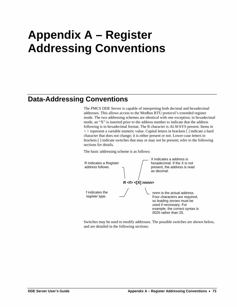
Appendix A – Register Addressing Conventions
Data-Addressing Conventions The PMCS DDE Server is capable of interpreting both decimal and hexadecimal addresses. This allows access to the Modbus RTU protocol’s extended register mode. The two addressing schemes are identical with one exception; in hexadecimal mode, an “X” is inserted prior to the address number to indicate that the address following is in hexadecimal format. The R character is ALWAYS present. Items in < > represent a variable numeric value. Capital letters in brackets [ ] indicate a hard character that does not change; it is either present or not. Lower-case letters in brackets [ ] indicate switches that may or may not be present; refer to the following sections for details.
The basic addressing scheme is as follows:
R indicates a Registeraddress follows.
f indicates theregister type.
X indicates a address ishexadecimal. If the X is notpresent, the address is readas decimal.
nnnn is the actual address.Four characters are required,so leading zeroes must beused if necessary. Forexample, the correct syntax is0025 rather than 25.
R <f> <[X] nnnn>
Switches may be used to modify addresses. The possible switches are shown below, and are detailed in the following sections:
DDE Server User’s Guide Appendix A – Register Addressing Conventions • 73
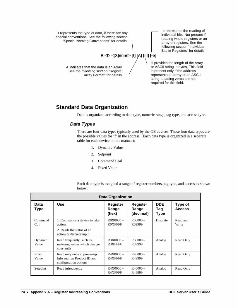
t represents the type of data, if there are anyspecial conventions. See the following section
“Special Naming Conventions” for details.
A indicates that the data is an Array.See the following section “Register
Array Format” for details.
-b represents the reading ofindividual bits. Not present ifreading whole registers or anarray of registers. See thefollowing section “IndividualBits in Registers” for details.
lll provides the length of the arrayor ASCII string in bytes, This fieldis present only if the addressrepresents an array or an ASCIIstring. Leading zeros are notrequired for this field.
R <f> <[X]nnnn> [t] [A] [lll] [-b]
Standard Data Organization Data is organized according to data type, numeric range, tag type, and access type.
Data Types There are four data types typically used by the GE devices. These four data types are the possible values for ‘f’ in the address. (Each data type is organized in a separate table for each device in this manual):
1. Dynamic Value
2. Setpoint
3. Command Coil
4. Fixed Value
Each data type is assigned a range of register numbers, tag type, and access as shown below:
Data Organization
Data Type
Use Register Range (hex)
Register Range (decimal)
DDE Tag Type
Type of Access
Command Coil
1. Commands a device to take action. 2. Reads the status of an action or discrete input.
R0X0000 – R0XFFFF
R00000 – R09999
Discrete Read and Write
Dynamic Value
Read frequently, such as metering values which change constantly
R3X0000 – R3XFFFF
R30000 – R39999
Analog Read Only
Fixed Value
Read only once at power-up. Info such as Product ID and configuration options
R4X0000 – R4XFFFF
R40000 – R49999
Analog Read Only
Setpoint Read infrequently R4X0000 – R4XFFFF
R40000 – R49999
Analog Read Only
74 • Appendix A – Register Addressing Conventions DDE Server User’s Guide
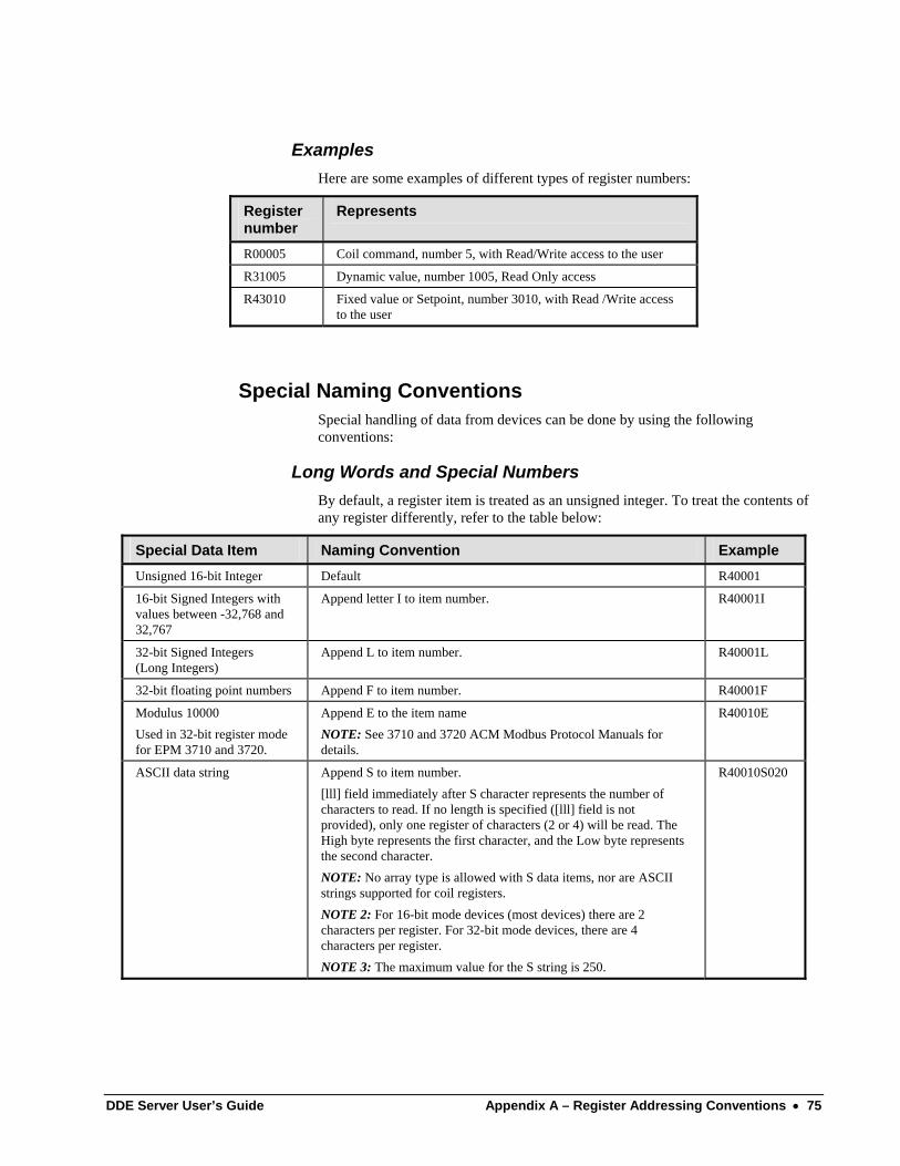
Examples Here are some examples of different types of register numbers:
Register number
Represents
R00005 Coil command, number 5, with Read/Write access to the user
R31005 Dynamic value, number 1005, Read Only access
R43010 Fixed value or Setpoint, number 3010, with Read /Write access to the user
Special Naming Conventions Special handling of data from devices can be done by using the following conventions:
Long Words and Special Numbers By default, a register item is treated as an unsigned integer. To treat the contents of any register differently, refer to the table below:
Special Data Item Naming Convention Example Unsigned 16-bit Integer Default R40001
16-bit Signed Integers with values between -32,768 and 32,767
Append letter I to item number. R40001I
32-bit Signed Integers (Long Integers)
Append L to item number. R40001L
32-bit floating point numbers Append F to item number. R40001F
Modulus 10000 Used in 32-bit register mode for EPM 3710 and 3720.
Append E to the item name NOTE: See 3710 and 3720 ACM Modbus Protocol Manuals for details.
R40010E
ASCII data string Append S to item number. [lll] field immediately after S character represents the number of characters to read. If no length is specified ([lll] field is not provided), only one register of characters (2 or 4) will be read. The High byte represents the first character, and the Low byte represents the second character. NOTE: No array type is allowed with S data items, nor are ASCII strings supported for coil registers. NOTE 2: For 16-bit mode devices (most devices) there are 2 characters per register. For 32-bit mode devices, there are 4 characters per register. NOTE 3: The maximum value for the S string is 250.
R40010S020
DDE Server User’s Guide Appendix A – Register Addressing Conventions • 75
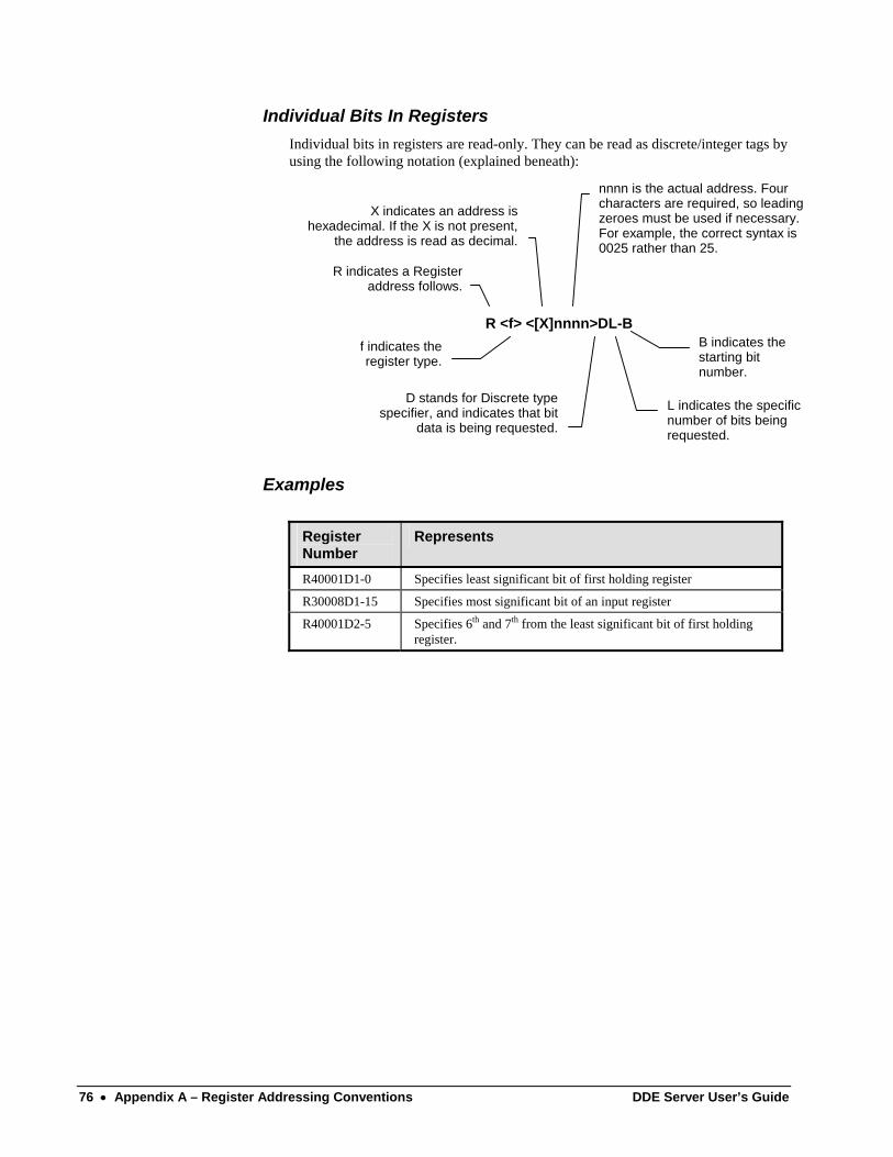
Individual Bits In Registers Individual bits in registers are read-only. They can be read as discrete/integer tags by using the following notation (explained beneath):
R indicates a Registeraddress follows.
f indicates theregister type.
X indicates an address ishexadecimal. If the X is not present,
the address is read as decimal.
nnnn is the actual address. Fourcharacters are required, so leadingzeroes must be used if necessary.For example, the correct syntax is0025 rather than 25.
D stands for Discrete typespecifier, and indicates that bit
data is being requested.
L indicates the specificnumber of bits beingrequested.
B indicates thestarting bitnumber.
R <f> <[X]nnnn>DL-B
Examples
Register Number
Represents
R40001D1-0 Specifies least significant bit of first holding register
R30008D1-15 Specifies most significant bit of an input register
R40001D2-5 Specifies 6th and 7th from the least significant bit of first holding register.
76 • Appendix A – Register Addressing Conventions DDE Server User’s Guide
Register Array Format If multiple data items are being requested from a single topic, it is more efficient to request a block of contiguous registers than to place multiple requests for single registers. This is referred to as register array format. The register array format is used for the following applications:
• to read a block of register values into a column of cells in a worksheet (such as Microsoft Excel).
• to pass waveform data to a client application (refer to GEH-6509, PMCS DDE Server Interface Reference, for details)
The rules for register arrays are as follows:
1. A register array, or series of consecutive registers, can be treated as a block of numeric values. Up to 100 sixteen-bit registers or 50 thirty-two-bit registers can be read as a block. Enter the starting register address, and append it with type specifier “A”, followed by the length field. For example, the register address R30501A12 accesses registers 501 through 512 as a block.
2. When the DDE Server returns a new value for a register array to the client, it is in the form of a character string containing a value for each register, separated by a carriage return.
For example, for R30021A6, the values returned might look like this:
50<cr><lf>
17<cr><lf>
0<cr><lf>
5<cr><lf>
1007<cr><lf>
20<cr><lf>
NOTE: All arrays must be terminated by a null character (ASCII 0).
3. When the client application writes a value to a register array, it must be in the form of a character string containing a value for each register in the array. The register values can be separated by commas, tabs, spaces, carriage returns or line feeds. For example, for R40001A6, the value string could be written:
1,2,3,4,5,6
or
1<tab>2<tab>3<tab>4<tab>5<tab>6
or
1 2 3 4 5 6
DDE Server User’s Guide Appendix A – Register Addressing Conventions • 77

(This page left blank intentionally)
78 • Appendix A – Register Addressing Conventions DDE Server User’s Guide
Glossary of Terms
Terms You Should Know Application Name – The name of the DDE Server program. This is supplied by the DDE client to establish a DDE conversation with a DDE Server application.
Client – An application requesting data from the DDE Server.
Communication Time-out – The maximum time to wait for a response from a device after Server has requested data from the device. If no response is received within the time-out period, the Server decides that the device will never respond and gives up on the current request for data, responding with a time-out error message. If a device times out repeatedly, the Server declares the device to be dead then occasionally queries the device to see if it has recovered.
DDE – Acronym for Dynamic Data Exchange, a message protocol that allows Windows applications to exchange data with one another.
GE32MODB – Application name for PMCS-RS485, RS-485 Modbus version.
GE32MTCP – Application name for PMCS-TCPIP, Modbus TCP/IP version
Generic Device – A user-defined device type that is not pre-configured for support by the PMCS DDE Server. The user must supply the associated register map, communications parameters, function codes, etc. PLCs, due to their highly flexible nature, are included in this device type.
Invalid Register Block – A range of register addresses within a register block that the PMCS DDE Server has been instructed not to scan. These may be addresses unused by the device itself, or simply registers in which the user is not interested.
Item – A name to identify the data in which communicating parties are interested. For the DDE Server, an item is the desired data point.
Mnemonic – Easily remembered name or string of characters representing the item register address, assigned by the user to make using the software easier.
Polling – Continuous scheduled acquisition of data. The DDE Server’s scanning of devices to satisfy client’s DDE requests.
Protocol Timer Tick – The time interval at which the Server executes DDE protocol; how often the Server listens for an incoming message from a device or transmits a message to a device.
Register – Location in a device’s memory containing a single binary datum. Each register has a particular address, and the DDE Server can access a register’s data by specifying the device and the register’s address. Mnemonics are used to make the numeric register addresses more meaningful; for example, VOLTS_A is understandable as the volts on phase A of a particular device, whereas the actual register address might be R10024-A1, which conveys no meaning to the reader.
DDE Server User’s Guide Glossary of Terms • 79
Register Map – Comprehensive listing of all register addresses and what they contain.
Scan Interval – Defines how often a device is to be scanned under optimal conditions; this is a target time which may not be attained due to network traffic load, number of devices, amount of data being requested, etc. A scan interval of 1000 msec (1 second) indicates that the DDE Server will attempt to scan the device as close to once per second as it can.
Server – A DDE-compliant MS Windows application providing data to other DDE-compliant applications (clients) on their request.
Time-out – The error message generated when no reply is received to a query after a given period of time.
Topic – A user-defined name associated with a specific device set to be polled at a particular frequency.
Valid Data Time-out – The time (in milliseconds) that elapses after a client has made a request for data to the PMCS DDE Server before a time-out error message is returned to the client.
80 • Glossary of Terms DDE Server User’s Guide
Index
C client, 2 client-server, 2 Configure menu, 32
D DDE, 2 DDE Server, 1 DDE Server icon, 9 Dynamic Data Exchange (DDE) Server, 2
E Ethernet, 2
H Help menu, 44
I Installing DDE Server, 3
M Main window, 10 Main window controls, 10 menu bar, 10 Modbus RTU, 2
P DDE Server, 1
S server, 2 Server menu, 26 System menu, 25
T Toolbar, 10, 44 Toolbar icons, 44
V View menu, 27
DDE Server User’s Guide Index • 81

USA & Canada: 1-800-547-8629 Global: (905) 294-6222 Fax: (905) 201-2098 Email: [email protected] <mailto:[email protected]>
GEH-6510 R045 01/02 © 2000 - 2005 General Electric Company
g GE MULTILIN General Electric Company 215 Anderson Avenue, Markham ON, L6E 1B3, CANADA.