plumbing submittal - hajoca · plumbing submittal panera bread #4460 ... submitted by accent...
TRANSCRIPT
Plumbing SubmittalPlumbing SubmittalPlumbing SubmittalPlumbing Submittal
PANERA BREAD #4460PANERA BREAD #4460PANERA BREAD #4460PANERA BREAD #4460
Submitted bySubmitted bySubmitted bySubmitted by
ACCENT PLUMBINGACCENT PLUMBINGACCENT PLUMBINGACCENT PLUMBING
9/27/20169/27/20169/27/20169/27/2016
MOORE SUPPLY COMOORE SUPPLY COMOORE SUPPLY COMOORE SUPPLY CO
8740 SHOAL CREEK BLVDAUSTIN, TX 78757-6816
Phone: 512 454-4616Fax: 512 454-4610
www.mooresupply.com
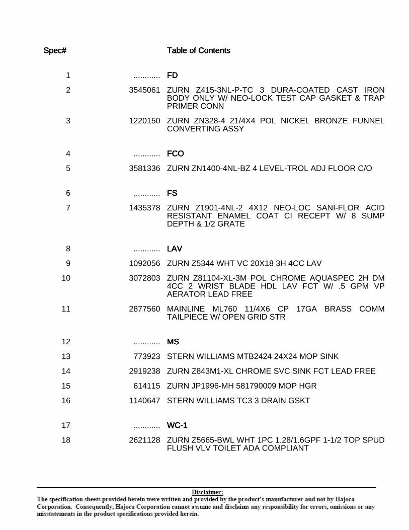
Spec#Spec#Spec#Spec# Table of ContentsTable of ContentsTable of ContentsTable of Contents
1 ............ FDFDFDFD
2 3545061 ZURN Z415-3NL-P-TC 3 DURA-COATED CAST IRONBODY ONLY W/ NEO-LOCK TEST CAP GASKET & TRAPPRIMER CONN
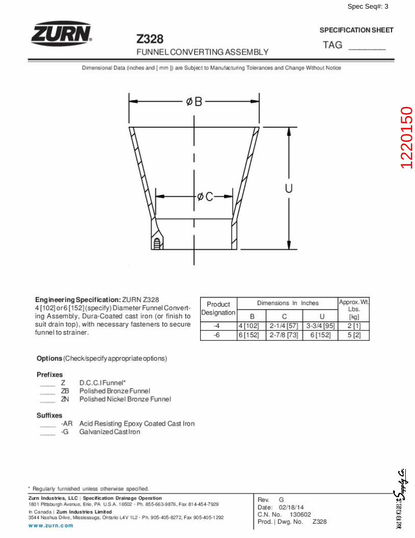
3 1220150 ZURN ZN328-4 21/4X4 POL NICKEL BRONZE FUNNELCONVERTING ASSY
4 ............ FCOFCOFCOFCO
5 3581336 ZURN ZN1400-4NL-BZ 4 LEVEL-TROL ADJ FLOOR C/O
6 ............ FSFSFSFS
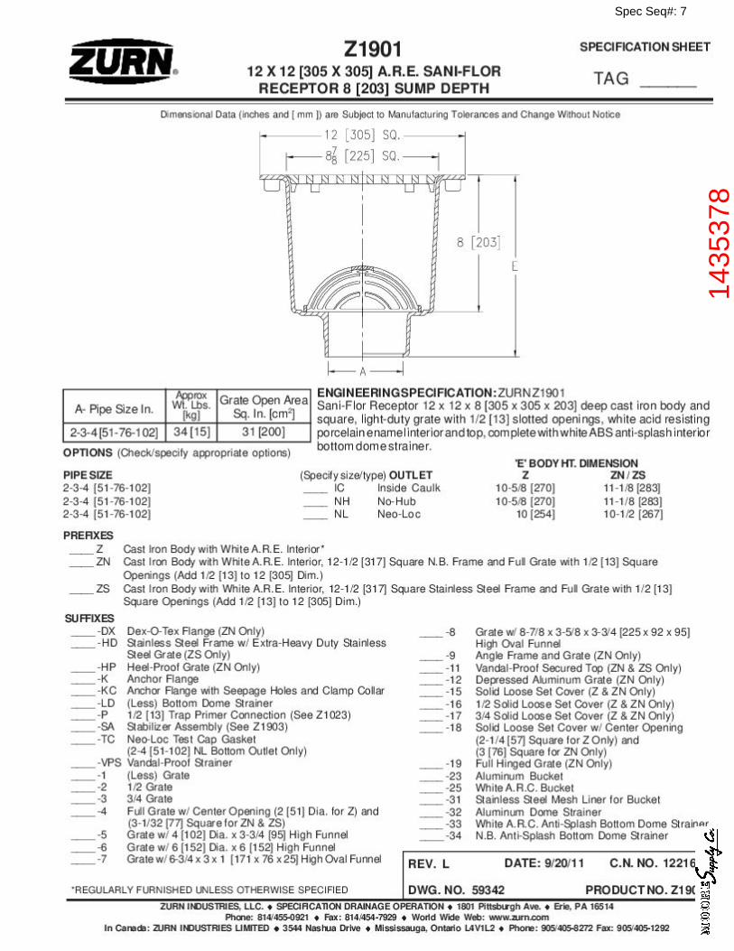
7 1435378 ZURN Z1901-4NL-2 4X12 NEO-LOC SANI-FLOR ACIDRESISTANT ENAMEL COAT CI RECEPT W/ 8 SUMPDEPTH & 1/2 GRATE
8 ............ LAVLAVLAVLAV
9 1092056 ZURN Z5344 WHT VC 20X18 3H 4CC LAV
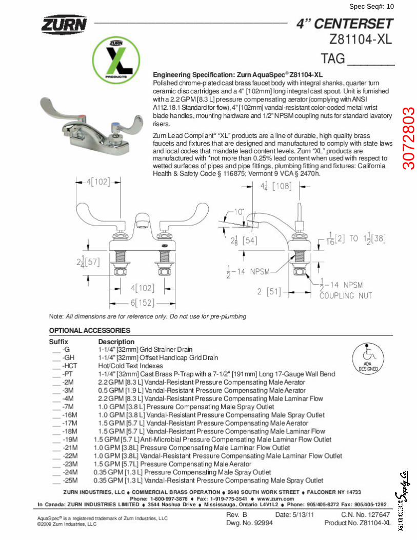
10 3072803 ZURN Z81104-XL-3M POL CHROME AQUASPEC 2H DM4CC 2 WRIST BLADE HDL LAV FCT W/ .5 GPM VPAERATOR LEAD FREE
11 2877560 MAINLINE ML760 11/4X6 CP 17GA BRASS COMMTAILPIECE W/ OPEN GRID STR
12 ............ MSMSMSMS
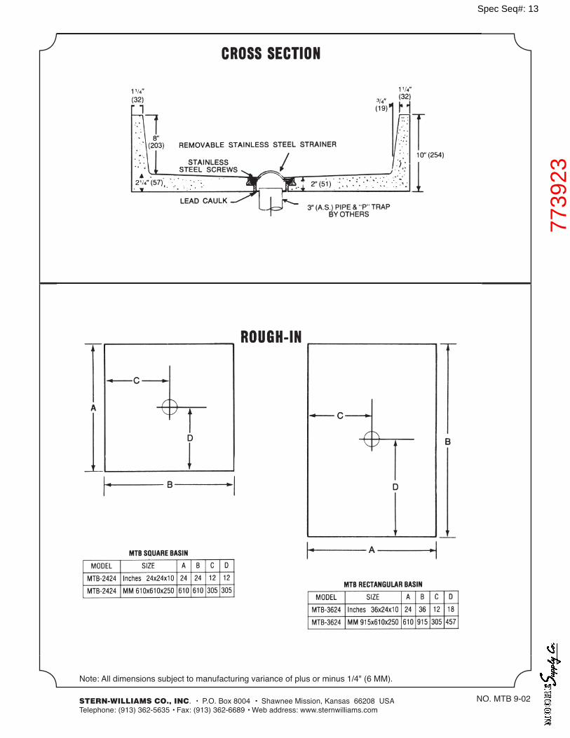
13 773923 STERN WILLIAMS MTB2424 24X24 MOP SINK
14 2919238 ZURN Z843M1-XL CHROME SVC SINK FCT LEAD FREE
15 614115 ZURN JP1996-MH 581790009 MOP HGR
16 1140647 STERN WILLIAMS TC3 3 DRAIN GSKT
17 ............ WC-1WC-1WC-1WC-1
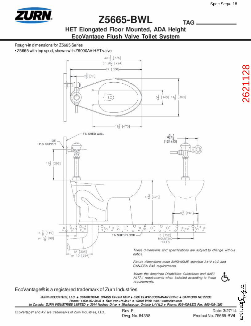
18 2621128 ZURN Z5665-BWL WHT 1PC 1.28/1.6GPF 1-1/2 TOP SPUDFLUSH VLV TOILET ADA COMPLIANT
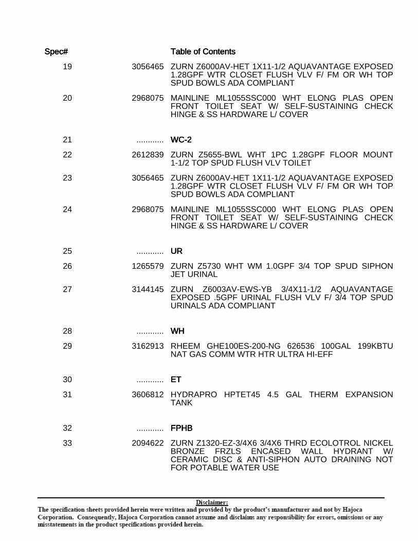
Spec#Spec#Spec#Spec# Table of ContentsTable of ContentsTable of ContentsTable of Contents
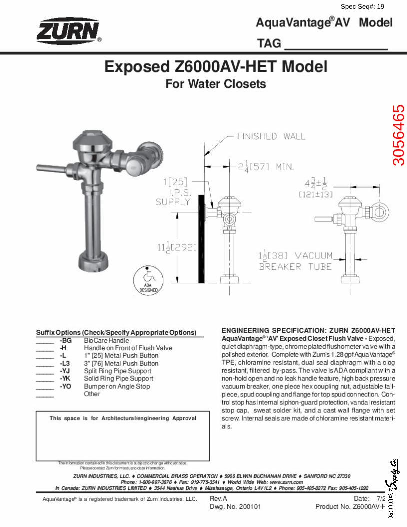
19 3056465 ZURN Z6000AV-HET 1X11-1/2 AQUAVANTAGE EXPOSED1.28GPF WTR CLOSET FLUSH VLV F/ FM OR WH TOPSPUD BOWLS ADA COMPLIANT
20 2968075 MAINLINE ML1055SSC000 WHT ELONG PLAS OPENFRONT TOILET SEAT W/ SELF-SUSTAINING CHECKHINGE & SS HARDWARE L/ COVER
21 ............ WC-2WC-2WC-2WC-2
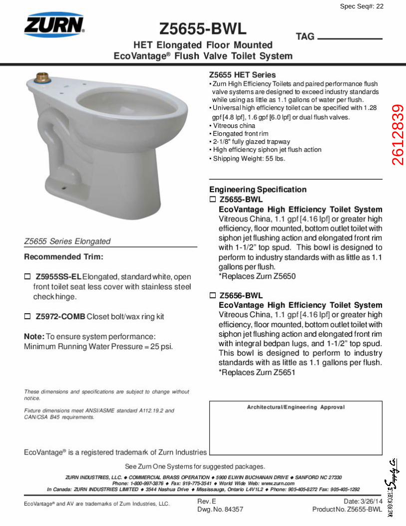
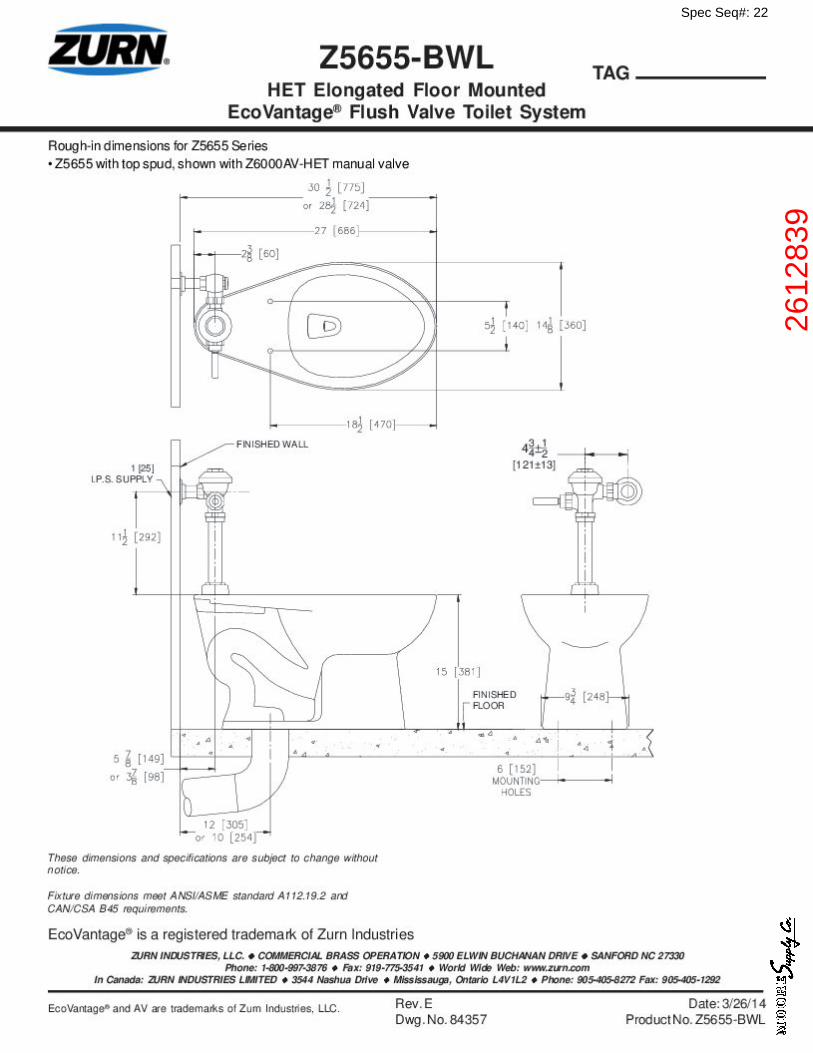
22 2612839 ZURN Z5655-BWL WHT 1PC 1.28GPF FLOOR MOUNT1-1/2 TOP SPUD FLUSH VLV TOILET
23 3056465 ZURN Z6000AV-HET 1X11-1/2 AQUAVANTAGE EXPOSED1.28GPF WTR CLOSET FLUSH VLV F/ FM OR WH TOPSPUD BOWLS ADA COMPLIANT
24 2968075 MAINLINE ML1055SSC000 WHT ELONG PLAS OPENFRONT TOILET SEAT W/ SELF-SUSTAINING CHECKHINGE & SS HARDWARE L/ COVER
25 ............ URURURUR
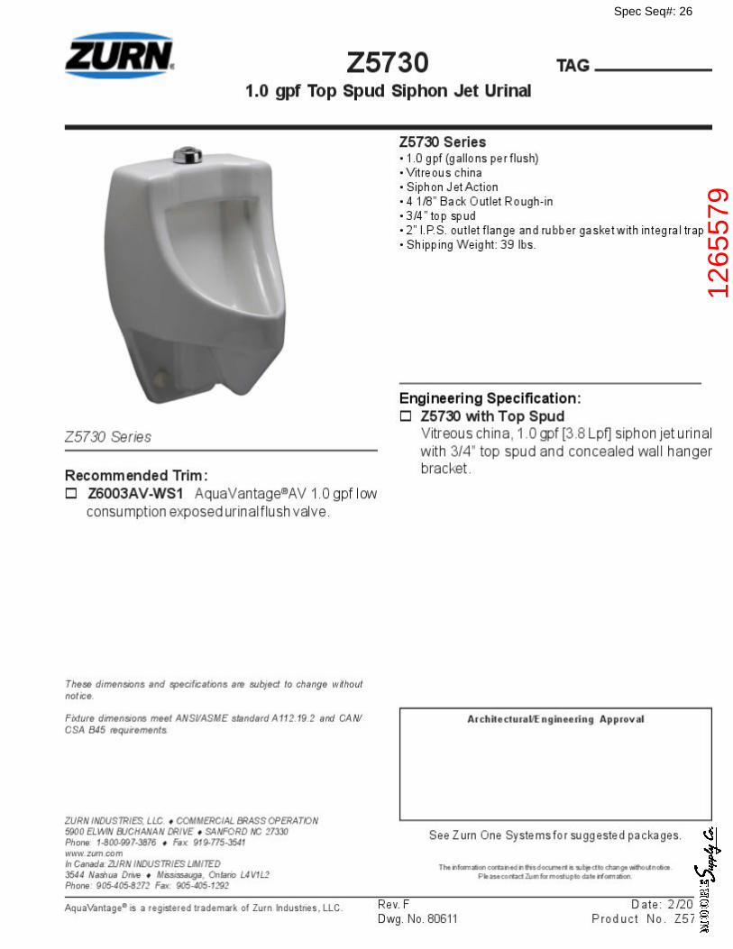
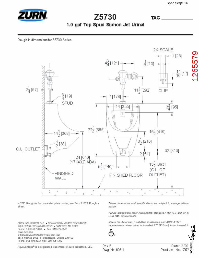
26 1265579 ZURN Z5730 WHT WM 1.0GPF 3/4 TOP SPUD SIPHONJET URINAL
27 3144145 ZURN Z6003AV-EWS-YB 3/4X11-1/2 AQUAVANTAGEEXPOSED .5GPF URINAL FLUSH VLV F/ 3/4 TOP SPUDURINALS ADA COMPLIANT
28 ............ WHWHWHWH
29 3162913 RHEEM GHE100ES-200-NG 626536 100GAL 199KBTUNAT GAS COMM WTR HTR ULTRA HI-EFF
30 ............ ETETETET
31 3606812 HYDRAPRO HPTET45 4.5 GAL THERM EXPANSIONTANK
32 ............ FPHBFPHBFPHBFPHB
33 2094622 ZURN Z1320-EZ-3/4X6 3/4X6 THRD ECOLOTROL NICKELBRONZE FRZLS ENCASED WALL HYDRANT W/CERAMIC DISC & ANTI-SIPHON AUTO DRAINING NOTFOR POTABLE WATER USE
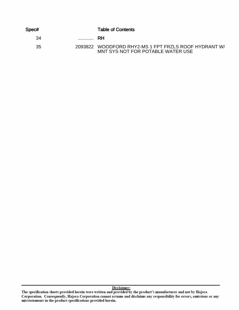
Spec#Spec#Spec#Spec# Table of ContentsTable of ContentsTable of ContentsTable of Contents
34 ............ RHRHRHRH
35 2093822 WOODFORD RHY2-MS 1 FPT FRZLS ROOF HYDRANT W/MNT SYS NOT FOR POTABLE WATER USE
Spec Seq#: 1
FD
*REGULARLY FURNISHED UNLESS OTHERWISE SPECIFIED
Dimensional Data (inches and [ mm ]) are Subject to Manufacturing Tolerances and Change Without Notice
SPECIFICATION SHEET
TAG _____
ZURN INDUSTRIES, INC. ♦♦♦♦♦ SPECIFICATION DRAINAGE OPERATION ♦♦♦♦♦ 1801 Pittsburgh Ave. ♦♦♦♦♦ Erie, PA 16514Phone: 814/455-0921 ♦♦♦♦♦ Fax: 814/454-7929 ♦♦♦♦♦ World Wide Web: www.zurn.com
In Canada: ZURN INDUSTRIES LIMITED ♦♦♦♦♦ 3544 Nashua Drive ♦♦♦♦♦ Mississauga, Ontario L4V1L2 ♦♦♦♦♦ Phone: 905/405-8272 Fax: 905/405-1292
®
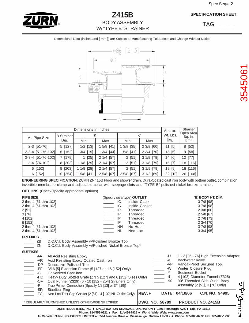
ENGINEERING SPECIFICATION: ZURN ZN415B Floor and shower drain, Dura-Coated cast iron body with bottom outlet, combinationinvertible membrane clamp and adjustable collar with seepage slots and "TYPE B" polished nickel bronze strainer.
OPTIONS (Check/specify appropriate options)
PIPE SIZE (Specify size/type) OUTLET 'E' BODY HT. DIM.2 thru 4 [51 thru 102] _____ IC Inside Caulk 3 7/8 [98]2 thru 4 [51 thru 102] _____ IG Inside Gasket 3 7/8 [98]2 [51] _____ IP Threaded 2 3/8 [60]3 [76] _____ IP Threaded 2 5/8 [67]4 [102] _____ IP Threaded 2 7/8 [73]6 [152] _____ IP Threaded 2 3/4 [70]2 thru 4 [51 thru 102] _____ NH No-Hub 3 7/8 [98]2 thru 4 [51 thru 102] _____ NL Neo-Loc 3 3/4 [95]
PREFIXES_____ ZB D.C.C.I. Body Assembly w/Polished Bronze Top_____ ZN D.C.C.I. Body Assembly w/Polished Nickel Bronze Top*
SUFFIXES_____ -AA All Acid Resisting Epoxy_____ -AR Acid Resisting Epoxy Coated Cast Iron_____ -DP Decorative Polished Top_____ -EF 3/16 [5] Extension Frame (5 [127 and 6 [152] Only)_____ -G Galvanized Cast Iron_____ -HD Heavy Duty Slotted Grate (ZN 5 [127] and 6 [152] Sizes Only)_____ -OF Oval Funnel (Z329) (6 - 10 [152 - 254] Strainers Only)_____ -P Trap Primer Connection (Specify 1/2 [13] or 3/4 [19])_____ -SR Stabilizer Ring_____ -TC Neo-Loc Test Cap Gasket (2 [51] - 4 [102] NL Outlet Only)
Z415BBODY ASSEMBLY
W/ "TYPE B" STRAINER
DWG. NO. 58789
REV. H
PRODUCT NO. Z415B
DATE: 04/10/06 C.N. NO. 94995
_____ -U 1 - 3 [25 - 76] High Extension Adapter_____ -V Backwater Valve_____ -VP Vandal-Proof Secured Top_____ -W Winter Closure Plug_____ -Y Sediment Bucket_____ -4 4 [102] Diameter Funnel (Z328)_____ -90 90° Threaded Side Outlet Body
Assembly (2 [51], 3 [76] Only)
Dimensions In Inches Approx.Wt. Lbs.
[kg]
StrainerOpen Area
Sq. In.[cm2]
A - Pipe Size B StrainerDia.
K K'
Min. Max. Min. Max.
2-3 [51-76] 5 [127] 1/2 [13] 1 5/8 [41] 1 3/8 [35] 2 3/8 [60] 11 [5] 8 [52]
2-3-4 [51-76-102] 6 [152] 3/4 [19] 1 3/4 [44] 1 5/8 [41] 2 3/4 [70] 13 [6] 9 [58]
2-3-4 [51-76-102] 7 [178] 1 [25] 2 1/4 [57] 2 [51] 3 1/8 [79] 14 [6] 12 [77]
3-4 [76-102] 8 [203] 1 1/8 [29] 2 1/4 [57] 2 [51] 3 1/8 [79] 16 [7] 18 [116]
6 [152] 8 [203] 1 1/8 [29] 2 1/4 [57] 2 [51] 3 1/8 [79] 18 [8] 18 [116]
6 [152] 10 [254] 1 5/8 [41 2 5/8 [67] 2 5/8 [67] 3 1/2 [89] 22 [10] 26 [168]
Spec Seq#: 2
3545
061
Spec Seq#: 3
1220
150
Spec Seq#: 4
FCO
*REGULARLY FURNISHED UNLESS OTHERWISE SPECIFIED
Dimensional Data (inches and [ mm ]) are Subject to Manufacturing Tolerances and Change Without Notice
ZURN INDUSTRIES, LLC. ♦♦♦♦♦ SPECIFICATION DRAINAGE OPERATION ♦♦♦♦♦ 1801 Pittsburgh Ave. ♦♦♦♦♦ Erie, PA 16514Phone: 814\455-0921 ♦♦♦♦♦ Fax: 814\454-7929 ♦♦♦♦♦ World Wide Web: www.zurn.com
In Canada: ZURN INDUSTRIES LIMITED ♦♦♦♦♦ 3544 Nashua Drive ♦♦♦♦♦ Mississauga, Ontario L4V1L2 ♦♦♦♦♦ Phone: 905\405-8272 Fax: 905\405-1292
SPECIFICATION SHEET
TAG _______®
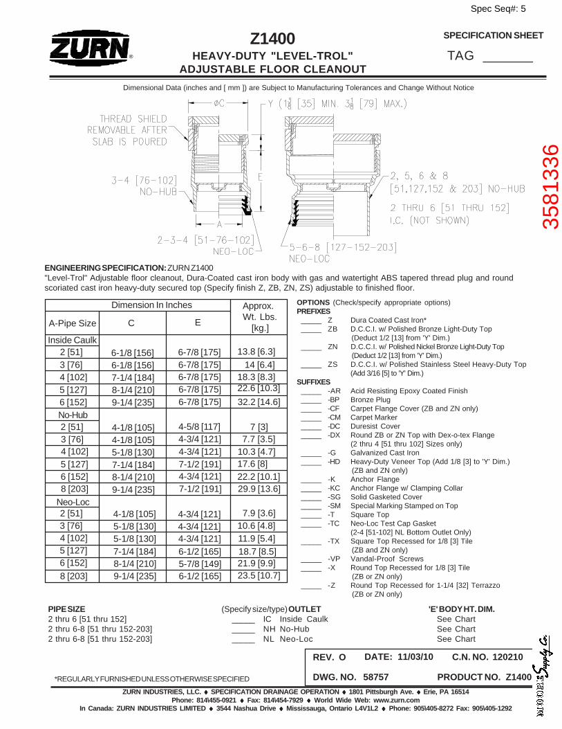
Z1400HEAVY-DUTY "LEVEL-TROL"
ADJUSTABLE FLOOR CLEANOUT
DWG. NO. 58757
REV. O
PRODUCT NO. Z1400
DATE: 11/03/10 C.N. NO. 120210
PIPE SIZE (Specify size/type) OUTLET 'E' BODY HT. DIM.2 thru 6 [51 thru 152] _____ IC Inside Caulk See Chart2 thru 6-8 [51 thru 152-203] _____ NH No-Hub See Chart2 thru 6-8 [51 thru 152-203] _____ NL Neo-Loc See Chart
OPTIONS (Check/specify appropriate options)PREFIXES
_____ Z Dura Coated Cast Iron*_____ ZB D.C.C.I. w/ Polished Bronze Light-Duty Top
(Deduct 1/2 [13] from 'Y' Dim.)_____ ZN D.C.C.I. w/ Polished Nickel Bronze Light-Duty Top
(Deduct 1/2 [13] from 'Y' Dim.)_____ ZS D.C.C.I. w/ Polished Stainless Steel Heavy-Duty Top
(Add 3/16 [5] to 'Y' Dim.)SUFFIXES
_____ -AR Acid Resisting Epoxy Coated Finish_____ -BP Bronze Plug_____ -CF Carpet Flange Cover (ZB and ZN only)_____ -CM Carpet Marker_____ -DC Duresist Cover_____ -DX Round ZB or ZN Top with Dex-o-tex Flange
(2 thru 4 [51 thru 102] Sizes only)_____ -G Galvanized Cast Iron_____ -HD Heavy-Duty Veneer Top (Add 1/8 [3] to 'Y' Dim.)
(ZB and ZN only)_____ -K Anchor Flange_____ -KC Anchor Flange w/ Clamping Collar_____ -SG Solid Gasketed Cover_____ -SM Special Marking Stamped on Top_____ -T Square Top_____ -TC Neo-Loc Test Cap Gasket
(2-4 [51-102] NL Bottom Outlet Only)_____ -TX Square Top Recessed for 1/8 [3] Tile
(ZB and ZN only)_____ -VP Vandal-Proof Screws_____ -X Round Top Recessed for 1/8 [3] Tile
(ZB or ZN only)_____ -Z Round Top Recessed for 1-1/4 [32] Terrazzo
(ZB or ZN only)
ENGINEERING SPECIFICATION: ZURN Z1400"Level-Trol" Adjustable floor cleanout, Dura-Coated cast iron body with gas and watertight ABS tapered thread plug and roundscoriated cast iron heavy-duty secured top (Specify finish Z, ZB, ZN, ZS) adjustable to finished floor.
18.7 [8.5]
7 [3]
8 [203]
Neo-Loc
No-Hub
Inside Caulk
A-Pipe Size C E
Approx.Wt. Lbs. [kg.]
Dimension In Inches
6 [152]5 [127]4 [102]3 [76]2 [51]
8 [203]6 [152]5 [127]4 [102]3 [76]2 [51]
6 [152]5 [127]4 [102]3 [76]2 [51] 13.8 [6.3]
14 [6.4]18.3 [8.3]22.6 [10.3]32.2 [14.6]
29.9 [13.6]
10.6 [4.8]7.9 [3.6]
11.9 [5.4]
21.9 [9.9]23.5 [10.7]
6-7/8 [175]6-7/8 [175]6-7/8 [175]6-7/8 [175]6-7/8 [175]
4-5/8 [117]4-3/4 [121]4-3/4 [121]7-1/2 [191]4-3/4 [121]7-1/2 [191]
4-3/4 [121]4-3/4 [121]4-3/4 [121]6-1/2 [165]5-7/8 [149]6-1/2 [165]
6-1/8 [156]6-1/8 [156]7-1/4 [184]8-1/4 [210]9-1/4 [235]
4-1/8 [105]4-1/8 [105]5-1/8 [130]7-1/4 [184]8-1/4 [210]9-1/4 [235]
4-1/8 [105]5-1/8 [130]5-1/8 [130]7-1/4 [184]8-1/4 [210]9-1/4 [235]
7.7 [3.5]10.3 [4.7]17.6 [8]22.2 [10.1]
Spec Seq#: 5
3581
336
Spec Seq#: 6
FS
Spec Seq#: 7
1435
378

Spec Seq#: 8
LAV
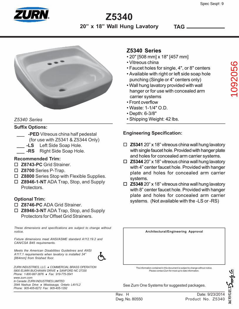
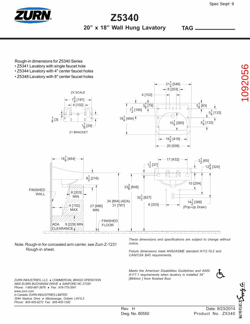
Z534020” x 18” Wall Hung Lavatory TAG
ZURN INDUSTRIES, LLC. ♦ COMMERCIAL BRASS OPERATION5900 ELWIN BUCHANAN DRIVE ♦ SANFORD NC 27330Phone: 1-800-997-3876 ♦ Fax: 919-775-3541www.zurn.comIn Canada: ZURN INDUSTRIES LIMITED3544 Nashua Drive ♦ Mississauga, Ontario L4V1L2Phone: 905-405-8272 Fax: 905-405-1292
Rev. H Date: 9/23/2014Dwg. No. 80550 Product No. Z5340
Z5340 Series• 20" [508 mm] x 18" [457 mm]• Vitreous china• Faucet holes for single, 4", or 8" centers• Available with right or left side soap hole punching (Single or 4” centers only)• Wall hung lavatory provided with wall hanger or for use with concealed arm carrier systems• Front overflow• Waste: 1-1/4" O.D.• Depth: 6-3/8"• Shipping Weight: 42 lbs.
Meets the American Disabilities Guidelines and ANSIA117.1 requirements when lavatory is installed 34”[864mm] from finished floor.
Engineering Specification:
Z5341 20” x 18” vitreous china wall hung lavatorywith single faucet hole. Provided with hanger plateand holes for concealed arm carrier systems.
Z5344 20” x 18” vitreous china wall hung lavatorywith 4” center faucet hole. Provided with hangerplate and holes for concealed arm carriersystems.
Z5348 20” x 18” vitreous china wall hung lavatorywith 8” center faucet hole. Provided with hangerplate and holes for concealed arm carriersystems. (Not available with the -LS or -RS)
These dimensions and specifications are subject to change withoutnotice.
Fixture dimensions meet ANSI/ASME standard A112.19.2 andCAN/CSA B45 requirements.
Z5340 Series
See Zurn One Systems for suggested packages.
Architectural/Engineering Approval
Suffix Options:___ -PED Vitreous china half pedestal
(for use with Z5341 & Z5344 Only)___ -LS Left Side Soap Hole.___ -RS Right Side Soap Hole.
Recommended Trim: Z8743-PC Grid Strainer. Z8700 Series P-Trap. Z8800 Series Stop with Flexible Supplies. Z8946-1-NT ADA Trap, Stop, and Supply
Protectors.
Optional Trim: Z8746-PC ADA Grid Strainer. Z8946-3-NT ADA Trap, Stop, and Supply
Protectors for Offset Grid Strainers.
The information contained in this document is subject to change without notice.Please contact Zurn for most up to date information.
Spec Seq#: 9
1092
056
Z534020” x 18” Wall Hung Lavatory TAG
ZURN INDUSTRIES, LLC. ♦ COMMERCIAL BRASS OPERATION5900 ELWIN BUCHANAN DRIVE ♦ SANFORD NC 27330Phone: 1-800-997-3876 ♦ Fax: 919-775-3541www.zurn.comIn Canada: ZURN INDUSTRIES LIMITED3544 Nashua Drive ♦ Mississauga, Ontario L4V1L2Phone: 905-405-8272 Fax: 905-405-1292
Rev. H Date: 9/23/2014Dwg. No. 80550 Product No. Z5340
Meets the American Disabilities Guidelines and ANSIA117.1 requirements when lavatory is installed 34”[864mm ] from finished floor.
These dimensions and specifications are subject to change withoutnotice.
Fixture dimensions meet ANSI/ASME standard A112.19.2 andCAN/CSA B45 requirements.
Rough-in dimensions for Z5340 Series• Z5341 Lavatory with single faucet hole• Z5344 Lavatory with 4" center faucet holes• Z5348 Lavatory with 8" center faucet holesAVAT O R I E S
Note: Rough-in for concealed arm carrier, see Zurn Z-1231 Rough-in sheet.
712 [190]
20 [508]
1612 [418]
318 [79]
8 [203]
10 [254]
1234 [324]
1412 [368]
(Pop-Up Drain)
112 [37]
212 [65]17 [432]
2112 [546]
314 [83]
514 [133]
514 [133]
4 [102]8 [203]
1814 [464]
34 [864] (ADA)31 [787]
812 [216]
3212 [827]
3338 [848]
1014 [260]
1814 [464]
Z1 BRACKET
118 [29]
734 [197]4 [102]
18 [3]
2X SCALE
27 [686]MIN.
8 [203]MIN.
6 [152]MAX.
ADACLEARANCE
9 [229] MIN.FINISHEDFLOOR
FINISHEDWALL
Spec Seq#: 9
1092
056
Spec Seq#: 10
3072
803
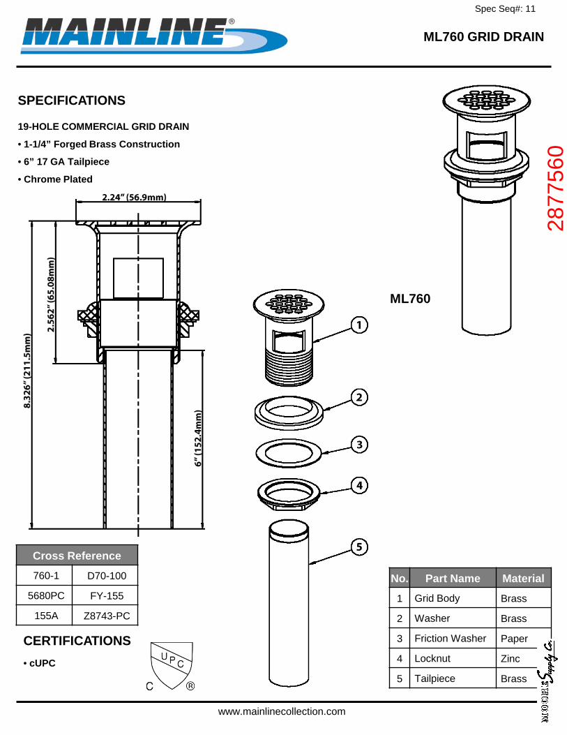
ML760 GRID DRAIN
SPECIFICATIONS
19-HOLE COMMERCIAL GRID DRAIN
• 1-1/4” Forged Brass Construction
• 6” 17 GA Tailpiece
• Chrome Plated
ML760
No. Part Name Material
1 Grid Body Brass
2 Washer Brass
3 Friction Washer Paper
4 Locknut Zinc
5 Tailpiece Brass
Cross Reference
760-1 D70-100
5680PC FY-155
155A Z8743-PC
www.mainlinecollection.com
CERTIFICATIONS • cUPC
Spec Seq#: 11
2877
560

Spec Seq#: 12
MS

JOB
LOCATION
ARCHITECT
ENGINEER
QUALITY OPTIONAL FITTINGSA. T-10-VB Mop-Service sink fitting with vacuum breaker, adjustable top brace, 3/4"
hose thread on spout with bucket hook inlets 8" on center, chrome finish.T-15 VB same as above with polished chrome finish.
B. T-35 Hose and wall hook. Hose 36" long, with 3/4" chrome couplings. Wall bracket of stainless steel.
C. T-40 Stainless Steel Mop Hanger of stainless steel with #4 finish. . . 24" long, with 3 rubber spring loaded grips.
D. BP Splash Catcher Panels of 20 ga. type 304 stainless steel.
C.
B.
A.
D.
Model No. ( ) Size ( ), as manufactured by Stern-Williams Co., Inc. Shoulders shall not be less than 8" high inside measurement, and not less than 1-1/4" wide. Drain shall be cast brass with stainless steel strainer cast integral and shall provide for a caulked lead connection not less than 1" deep to a 3" pipe. Receptor composed of pearl grey marble chips and white Portland cement ground smooth, grouted and sealed to resist stains.
An optional anodized extruded aluminum or vinyl bumper guard is offered for exposed sides. Cap to be attached on the job.
MTB®ARCHITECTURALSPECIFICATIONS
MODEL SIZE ALUMINUM OR VINYL CAP FOR EXPOSED SIDES MTB SQUARE BASIN■ MTB-2424 24”x24"x10” ■ CAP ON 1 SIDE ■ CAP ON 2 SIDES ■ CAP ON 3 SIDES MTB RECTANGULAR BASIN■ MTB-3624 36”x24"x10” ■ CAP ON 1 SIDE ■ CAP ON 2 SIDES ■ CAP ON 3 SIDES
A-20
V-70
A-20 Aluminum bumper guardsV-70 Vinyl bumper guards-SS Stainless steel caps, cast integral during production
Spec Seq#: 13
7739
23
NO. MTB 9-02
Note: All dimensions subject to manufacturing variance of plus or minus 1/4" (6 MM).
STERN-WILLIAMS CO., INC. • P.O. Box 8004 • Shawnee Mission, Kansas 66208 USATelephone: (913) 362-5635 • Fax: (913) 362-6689 • Web address: www.sternwilliams.com
Spec Seq#: 13
7739
23
TAG _______
AquaSpec® is a registered trademark of Zurn Industries, LLC©2010 Zurn Industries, LLC
ZURN INDUSTRIES, LLC ♦♦♦♦♦ COMMERCIAL BRASS OPERATION ♦♦♦♦♦ 2640 SOUTH WORK STREET ♦♦♦♦♦ FALCONER NY 14733Phone: 1-800-997-3876 ♦♦♦♦♦ Fax: 1-919-775-3541 ♦♦♦♦♦ www.zurn.com
In Canada: ZURN INDUSTRIES LIMITED ♦♦♦♦♦ 3544 Nashua Drive ♦♦♦♦♦ Mississauga, Ontario L4V1L2 ♦♦♦♦♦ Phone: 905/405-8272 Fax: 905/405-1292
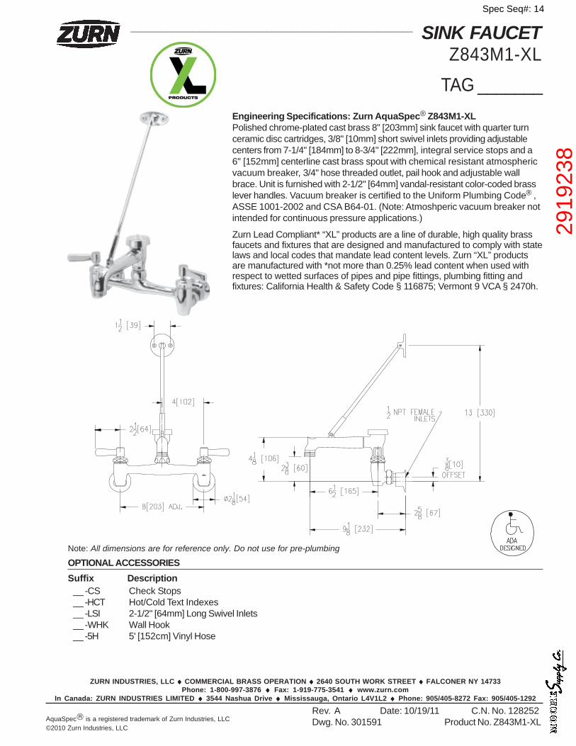
______________________________________________________ SINK FAUCETZ843M1-XL
Note: All dimensions are for reference only. Do not use for pre-plumbing
Rev. A Date: 10/19/11 C.N. No. 128252Dwg. No. 301591 Product No. Z843M1-XL
OPTIONAL ACCESSORIESSuffix Description
Engineering Specifications: Zurn AquaSpec® Z843M1-XLPolished chrome-plated cast brass 8" [203mm] sink faucet with quarter turnceramic disc cartridges, 3/8" [10mm] short swivel inlets providing adjustablecenters from 7-1/4" [184mm] to 8-3/4" [222mm], integral service stops and a6" [152mm] centerline cast brass spout with chemical resistant atmosphericvacuum breaker, 3/4" hose threaded outlet, pail hook and adjustable wallbrace. Unit is furnished with 2-1/2" [64mm] vandal-resistant color-coded brasslever handles. Vacuum breaker is certified to the Uniform Plumbing Code® ,ASSE 1001-2002 and CSA B64-01. (Note: Atmoshperic vacuum breaker notintended for continuous pressure applications.)
Zurn Lead Compliant* “XL” products are a line of durable, high quality brassfaucets and fixtures that are designed and manufactured to comply with statelaws and local codes that mandate lead content levels. Zurn “XL” productsare manufactured with *not more than 0.25% lead content when used withrespect to wetted surfaces of pipes and pipe fittings, plumbing fitting andfixtures: California Health & Safety Code § 116875; Vermont 9 VCA § 2470h.
__ -CS Check Stops__ -HCT Hot/Cold Text Indexes__ -LSI 2-1/2" [64mm] Long Swivel Inlets__ -WHK Wall Hook__ -5H 5' [152cm] Vinyl Hose
Spec Seq#: 14
2919
238
Spec Seq#: 15
6141
15
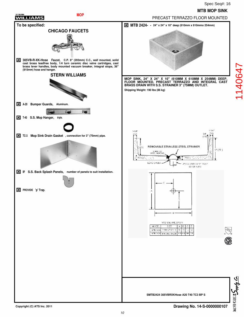
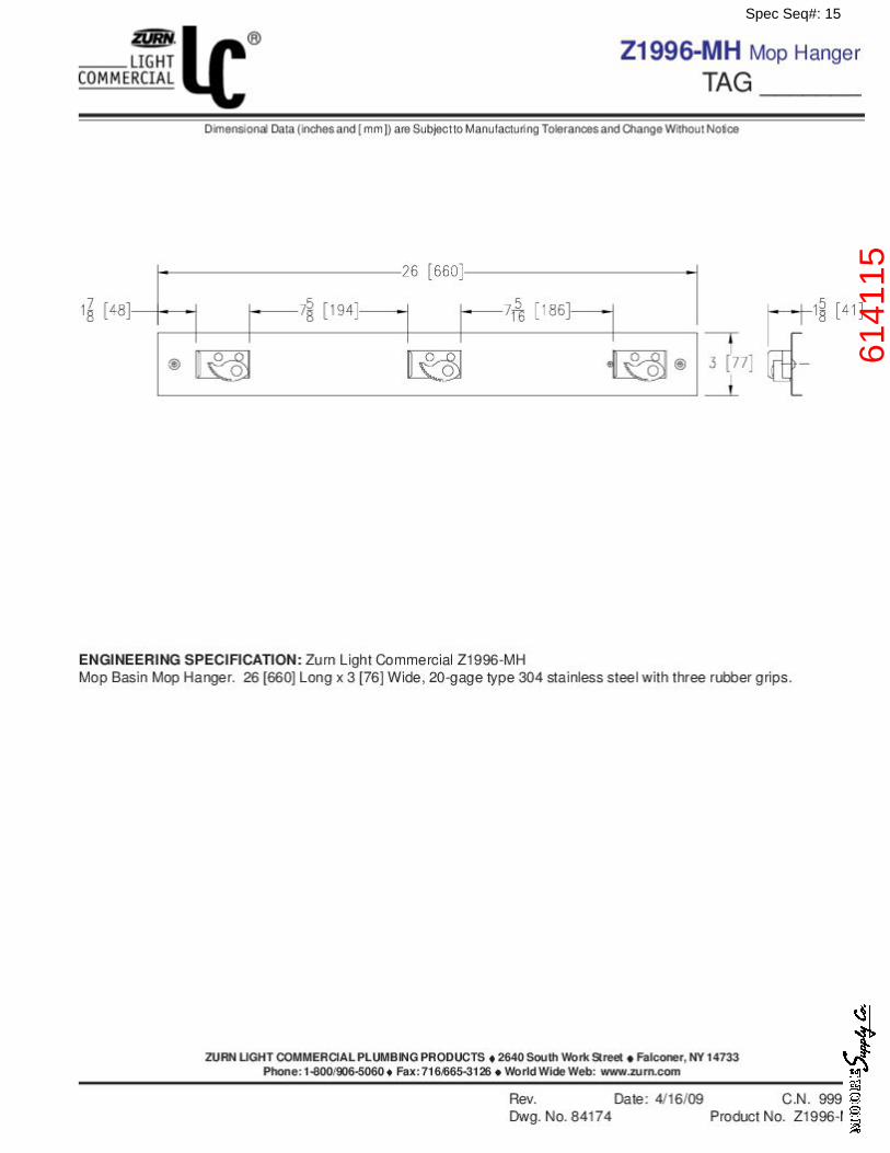
MOP MTB MOP SINK
PRECAST TERRAZZO FLOOR MOUNTED
To be specified:
CHICAGO FAUCETS
305VB-R-XK-Hose Faucet, C.P. 8" (203mm) C.C., wall mounted, solidcast brass leadfree body, 1/4 turn ceramic disc valve cartridges, castbrass lever handles, body mounted vacuum breaker, integral stops, 36"(915mm) hose and hanger.
STERN WILLIAMS
A-20 Bumper Guards, Aluminum.
T-40 S.S. Mop Hanger, triple.
TC-3 Mop Sink Drain Gasket , connection for 3" (75mm) pipe.
BP S.S. Back Splash Panels, number of panels to suit installation.
PROVIDE 'p' Trap.
MTB 2424- - 24" x 24" x 10" deep (610mm x 610mmx 254mm)
MOP SINK, 24" X 24" X 10" (610MM X 610MM X 254MM) DEEP,FLOOR MOUNTED, PRECAST TERRAZZO AND INTEGRAL CASTBRASS DRAIN WITH S.S. STRAINER 3" (75MM) OUTLET.
Shipping Weight: 190 lbs (86 kg)
SMTB2424 305VBRXKHose A20 T40 TC3 BP S
Copyright (C) ATS Inc. 2011 Drawing No. 14-S-0000000107
10
Spec Seq#: 16
1140
647

Spec Seq#: 17
WC-1
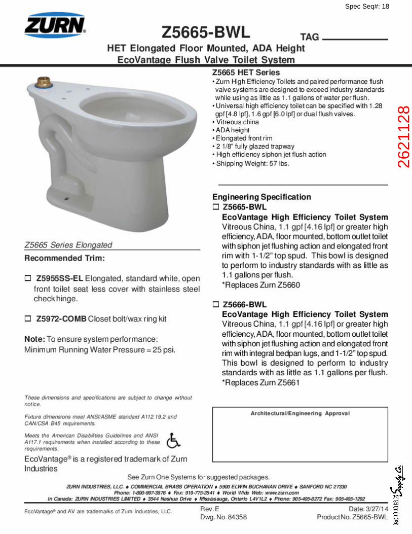
Spec Seq#: 18
2621
128
Spec Seq#: 18
2621
128
Spec Seq#: 19
3056
465

Mainline Plastic CommercialElongated Toilet Seat | rev. 07-6-2012
PRODUCT SPECIFICATIONS
All dimensions listed are nominal. MAINLINE® reserves the right to make product and material changes at any time without notice.
Contact your sales representative for more information or visit our website at mainlinecollection.com
WarrantySee warranty information for more details.
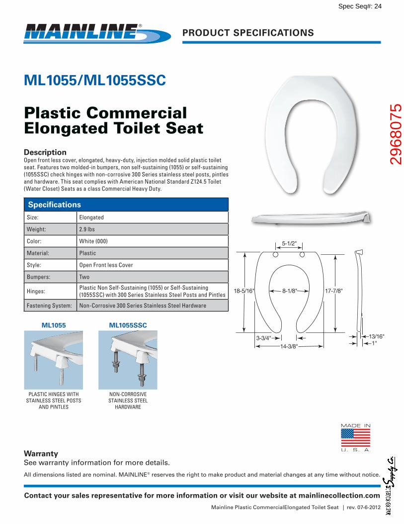
ML1055/ML1055SSC
Plastic Commercial Elongated Toilet SeatDescriptionOpen front less cover, elongated, heavy-duty, injection molded solid plastic toilet seat. Features two molded-in bumpers, non self-sustaining (1055) or self-sustaining (1055SSC) check hinges with non-corrosive 300 Series stainless steel posts, pintles and hardware. This seat complies with American National Standard Z124.5 Toilet (Water Closet) Seats as a class Commercial Heavy Duty.
PLASTIC HINGES WITH STAINLESS STEEL POSTS
AND PINTLES
NON-CORROSIVE STAINLESS STEEL
HARDWARE
3-3/4"
18-5/16" 8-1/8" 17-7/8"
14-3/8"
5-1/2"
13/16"1"
Specifications
Size: Elongated
Weight: 2.9 lbs
Color: White (000)
Material: Plastic
Style: Open Front less Cover
Bumpers: Two
Hinges: Plastic Non Self-Sustaining (1055) or Self-Sustaining (1055SSC) with 300 Series Stainless Steel Posts and Pintles
Fastening System: Non-Corrosive 300 Series Stainless Steel Hardware
ML1055 ML1055SSC
Spec Seq#: 20
2968
075

Spec Seq#: 21
WC-2
Spec Seq#: 22
2612
839
Spec Seq#: 22
2612
839

Spec Seq#: 23
3056
465
Mainline Plastic CommercialElongated Toilet Seat | rev. 07-6-2012
PRODUCT SPECIFICATIONS
All dimensions listed are nominal. MAINLINE® reserves the right to make product and material changes at any time without notice.
Contact your sales representative for more information or visit our website at mainlinecollection.com
WarrantySee warranty information for more details.
ML1055/ML1055SSC
Plastic Commercial Elongated Toilet SeatDescriptionOpen front less cover, elongated, heavy-duty, injection molded solid plastic toilet seat. Features two molded-in bumpers, non self-sustaining (1055) or self-sustaining (1055SSC) check hinges with non-corrosive 300 Series stainless steel posts, pintles and hardware. This seat complies with American National Standard Z124.5 Toilet (Water Closet) Seats as a class Commercial Heavy Duty.
PLASTIC HINGES WITH STAINLESS STEEL POSTS
AND PINTLES
NON-CORROSIVE STAINLESS STEEL
HARDWARE
3-3/4"
18-5/16" 8-1/8" 17-7/8"
14-3/8"
5-1/2"
13/16"1"
Specifications
Size: Elongated
Weight: 2.9 lbs
Color: White (000)
Material: Plastic
Style: Open Front less Cover
Bumpers: Two
Hinges: Plastic Non Self-Sustaining (1055) or Self-Sustaining (1055SSC) with 300 Series Stainless Steel Posts and Pintles
Fastening System: Non-Corrosive 300 Series Stainless Steel Hardware
ML1055 ML1055SSC
Spec Seq#: 24
2968
075

Spec Seq#: 25
UR
Spec Seq#: 26
1265
579
Spec Seq#: 26
1265
579
ZURN INDUSTRIES, LLC. COMMERCIAL BRASS OPERATION 5900 ELWIN BUCHANAN DRIVE SANFORD NC 27330PHONE: 1-800-997-3876 FAX: 919-775-3541 WORLD WIDE WEB: WWW.ZURN.COM
IN CANADA: ZURN INDUSTRIES LIMITED 3544 NASHUA DRIVE MISSISSAUGA, ONTARIO L4V1L2 PHONE: 905-405-8272 FAX: 905-405-1292
Aquaflush® is a registered trademark of Zurn Industries, LLC.
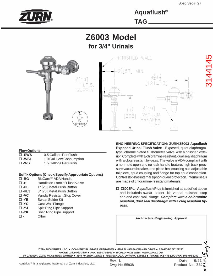
Z6003 Modelfor 3/4" Urinals
Architectural/Engineering Approval
Flow Options -EWS 0.5 Gallons Per Flush -WS1 1.0 Gal. Low Consumption -WS 1.5 Gallons Per Flush
Rev. L Date: 9/21/11Dwg. No. 55938 Product No. Z6003
ENGINEERING SPECIFICATION: ZURN Z6003 AquaflushExposed Urinal Flush Valve - Exposed, quiet diaphragm-type, chrome plated flushometer valve with a polished exte-rior. Complete with a chloramine resistant, dual seal diaphragmwith a clog resistant by-pass. The valve is ADA compliant witha non-hold open and no leak handle feature, high back pres-sure vacuum breaker, one piece hex coupling nut, adjustabletailpiece, spud coupling and flange for top spud connection.Control stop has internal siphon-guard protection. Internal sealsare made of chloramine resistant materials.
Aquaflush
® TAG
-Z6003PL - Aquaflush Plus is furnished as specified aboveand includeds sweat solder kit, vandal resistant stopcap,and cast wall flange. Complete with a chloramineresistant, dual seal diaphragm with a clog resistant by-pass.
Suffix Options (Check/Specify Appropriate Options) -BG BioCareTM ADA Handle -H Handle on Front of Flush Valve -HL 1" [25] Metal Push Button -HL3 3" [76] Metal Push Button -VC Vandal Resistant Stop Cover -YB Sweat Solder Kit -YC Cast Wall Flange -YJ Split Ring Pipe Support -YK Solid Ring Pipe Support - Other
Spec Seq#: 27
3144
145

Spec Seq#: 28
WH
PRINTED IN U.S.A. 05/15 WP FORM NO. RR102C-18 Rev. 9
Water Commercial GasSPIDERfire Water Heaters
INTEGRATED AIR & WATERINTEGRATED HOME COMFORT
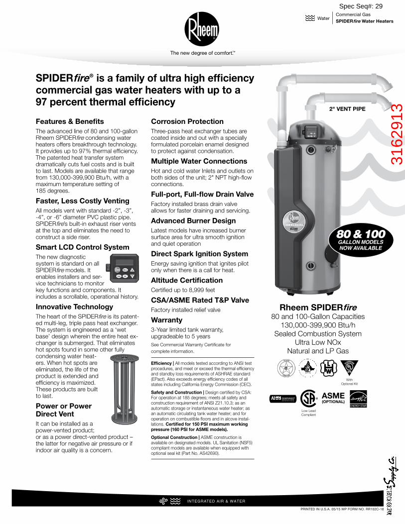
Features & BenefitsThe advanced line of 80 and 100-gallon Rheem SPIDERfire condensing water heaters offers breakthrough technology. It provides up to 97% thermal efficiency. The patented heat transfer system dramatically cuts fuel costs and is built to last. Models are available that range from 130,000-399,900 Btu/h, with a maximum temperature setting of 185 degrees.
Faster, Less Costly VentingAll models vent with standard -2”, -3”, -4”, or -6” diameter PVC plastic pipe. SPIDERfire’s built-in exhaust riser vents at the top and eliminates the need to construct a side riser.
Smart LCD Control SystemThe new diagnostic system is standard on all SPIDERfire models. It enables installers and ser-vice technicians to monitor key functions and components. It includes a scrollable, operational history.
Innovative TechnologyThe heart of the SPIDERfire is its patent-ed multi-leg, triple pass heat exchanger. The system is engineered as a ‘wet base’ design wherein the entire heat ex-changer is submerged. That eliminates hot spots found in some other fully condensing water heat-ers. When hot spots are eliminated, the life of the product is extended and efficiency is maximized. These products are built to last.
Power or Power Direct Vent It can be installed as a power-vented product; or as a power direct-vented product – the latter for negative air pressure or if indoor air quality is a concern.
Corrosion ProtectionThree-pass heat exchanger tubes are coated inside and out with a specially formulated porcelain enamel designed to protect against condensation.
Multiple Water Connections Hot and cold water Inlets and outlets on both sides of the unit; 2" NPT high-flow connections.
Full-port, Full-flow Drain ValveFactory installed brass drain valve allows for faster draining and servicing.
Advanced Burner DesignLatest models have increased burner surface area for ultra smooth ignition and quiet operation
Direct Spark Ignition SystemEnergy saving ignition that ignites pilot only when there is a call for heat.
Altitude CertificationCertified up to 8,999 feet
CSA/ASME Rated T&P ValveFactory installed relief valve
Warranty3-Year limited tank warranty, upgradeable to 5 yearsSee Commercial Warranty Certificate for complete information.
Efficiency | All models tested according to ANSI test procedures, and meet or exceed the thermal efficiency and standby loss requirements of ASHRAE standard (EPact). Also exceeds energy efficiency codes of all states including California Energy Commission (CEC).
Safety and Construction | Design certified by CSA: For operation at 185 degrees; meets all safety and construction requirement of ANSI Z21.10.3; as an automatic storage or instantaneous water heater; as an automatic circulating tank water heater; and for operation on combustible floors and in alcove instal-lations. Certified for 150 PSI maximum working pressure (160 PSI for ASME models).
Optional Construction | ASME construction is available on designated models. UL Sanitation (NSF5) compliant models are available when equipped with optional seal kit (Part No. AS42690).
SPIDERfire® is a family of ultra high efficiency commercial gas water heaters with up to a97 percent thermal efficiency
Rheem SPIDERfire80 and 100-Gallon Capacities
130,000-399,900 Btu/hSealed Combustion System
Ultra Low NOxNatural and LP Gas
80 & 100GALLON MODELSNOW AVAILABLE
2" VENT PIPE
With Optional Kit
Low Lead Compliant
ASME(OPTIONAL)
Spec Seq#: 29
3162
913
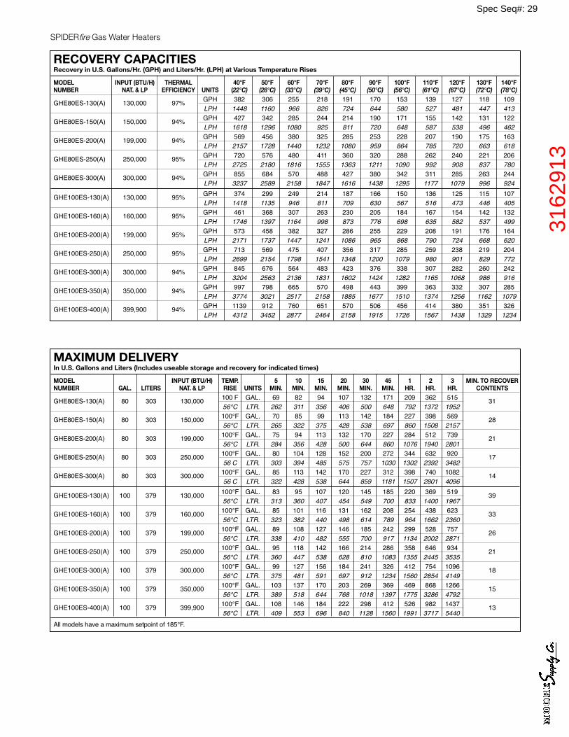
MAXIMUM DELIVERY In U.S. Gallons and Liters (Includes useable storage and recovery for indicated times)
MODEL INPUT (BTU/H) TEMP. 5 10 15 20 30 45 1 2 3 MIN. TO RECOVER NUMBER GAL. LITERS NAT. & LP RISE UNITS MIN. MIN. MIN. MIN. MIN. MIN. HR. HR. HR. CONTENTS
GHE80ES-130(A) 80 303 130,000 100 F GAL. 69 82 94 107 132 171 209 362 515 31 56°C LTR. 262 311 356 406 500 648 792 1372 1952
GHE80ES-150(A) 80 303 150,000 100°F GAL. 70 85 99 113 142 184 227 398 569 28 56°C LTR. 265 322 375 428 538 697 860 1508 2157
GHE80ES-200(A) 80 303 199,000 100°F GAL. 75 94 113 132 170 227 284 512 739 21 56°C LTR. 284 356 428 500 644 860 1076 1940 2801
GHE80ES-250(A) 80 303 250,000 100°F GAL. 80 104 128 152 200 272 344 632 920 17 56 C LTR. 303 394 485 575 757 1030 1302 2392 3482
GHE80ES-300(A) 80 303 300,000 100°F GAL. 85 113 142 170 227 312 398 740 1082 14 56 C LTR. 322 428 538 644 859 1181 1507 2801 4096
GHE100ES-130(A) 100 379 130,000 100°F GAL. 83 95 107 120 145 185 220 369 519 39 56°C LTR. 313 360 407 454 549 700 833 1400 1967
GHE100ES-160(A) 100 379 160,000 100°F GAL. 85 101 116 131 162 208 254 438 623 33 56°C LTR. 323 382 440 498 614 789 964 1662 2360
GHE100ES-200(A) 100 379 199,000 100°F GAL. 89 108 127 146 185 242 299 528 757 26 56°C LTR. 338 410 482 555 700 917 1134 2002 2871
GHE100ES-250(A) 100 379 250,000 100°F GAL. 95 118 142 166 214 286 358 646 934 21 56°C LTR. 360 447 538 628 810 1083 1355 2445 3535
GHE100ES-300(A) 100 379 300,000 100°F GAL. 99 127 156 184 241 326 412 754 1096 18 56°C LTR. 375 481 591 697 912 1234 1560 2854 4149
GHE100ES-350(A) 100 379 350,000 100°F GAL. 103 137 170 203 269 369 469 868 1266 15 56°C LTR. 389 518 644 768 1018 1397 1775 3286 4792
GHE100ES-400(A) 100 379 399,900 100°F GAL. 108 146 184 222 298 412 526 982 1437 13 56°C LTR. 409 553 696 840 1128 1560 1991 3717 5440 All models have a maximum setpoint of 185°F.
RECOVERY CAPACITIESRecovery in U.S. Gallons/Hr. (GPH) and Liters/Hr. (LPH) at Various Temperature Rises
MODEL INPUT (BTU/H) THERMAL 40°F 50°F 60°F 70°F 80°F 90°F 100°F 110°F 120°F 130°F 140°F NUMBER NAT. & LP EFFICIENCY UNITS (22°C) (28°C) (33°C) (39°C) (45°C) (50°C) (56°C) (61°C) (67°C) (72°C) (78°C)
GHE80ES-130(A) 130,000 97% GPH 382 306 255 218 191 170 153 139 127 118 109 LPH 1448 1160 966 826 724 644 580 527 481 447 413
GHE80ES-150(A) 150,000 94% GPH 427 342 285 244 214 190 171 155 142 131 122 LPH 1618 1296 1080 925 811 720 648 587 538 496 462 GHE80ES-200(A) 199,000 94% GPH 569 456 380 325 285 253 228 207 190 175 163 LPH 2157 1728 1440 1232 1080 959 864 785 720 663 618
GHE80ES-250(A) 250,000 95% GPH 720 576 480 411 360 320 288 262 240 221 206 LPH 2725 2180 1816 1555 1363 1211 1090 992 908 837 780 GHE80ES-300(A) 300,000 94% GPH 855 684 570 488 427 380 342 311 285 263 244 LPH 3237 2589 2158 1847 1616 1438 1295 1177 1079 996 924
GHE100ES-130(A) 130,000 95% GPH 374 299 249 214 187 166 150 136 125 115 107 LPH 1418 1135 946 811 709 630 567 516 473 446 405 GHE100ES-160(A) 160,000 95% GPH 461 368 307 263 230 205 184 167 154 142 132 LPH 1746 1397 1164 998 873 776 698 635 582 537 499 GHE100ES-200(A) 199,000 95% GPH 573 458 382 327 286 255 229 208 191 176 164 LPH 2171 1737 1447 1241 1086 965 868 790 724 668 620
GHE100ES-250(A) 250,000 95% GPH 713 569 475 407 356 317 285 259 238 219 204 LPH 2699 2154 1798 1541 1348 1200 1079 980 901 829 772 GHE100ES-300(A) 300,000 94% GPH 845 676 564 483 423 376 338 307 282 260 242 LPH 3204 2563 2136 1831 1602 1424 1282 1165 1068 986 916
GHE100ES-350(A) 350,000 94% GPH 997 798 665 570 498 443 399 363 332 307 285 LPH 3774 3021 2517 2158 1885 1677 1510 1374 1256 1162 1079
GHE100ES-400(A) 399,900 94% GPH 1139 912 760 651 570 506 456 414 380 351 326 LPH 4312 3452 2877 2464 2158 1915 1726 1567 1438 1329 1234
SPIDERfire Gas Water Heaters
2
Spec Seq#: 29
3162
913
SPIDERfire Gas Water Heaters
3
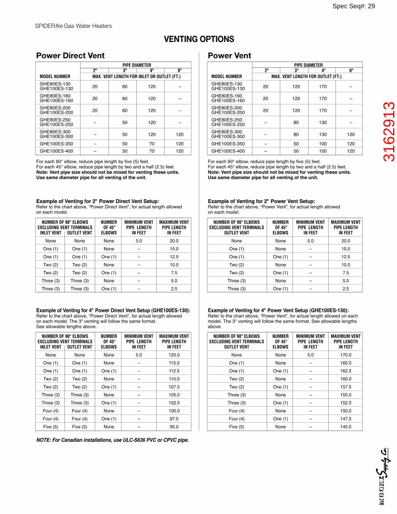
VENTING OPTIONS
Example of Venting for 2" Power Direct Vent Setup:Refer to the chart above, “Power Direct Vent”, for actual length allowed on each model.
NUMBER OF 90° ELBOWS NUMBER MINIMUM VENT MAXIMUM VENT EXCLUDING VENT TERMINALS OF 45° PIPE LENGTH PIPE LENGTH INLET VENT OUTLET VENT ELBOWS IN FEET IN FEET
None None None 5.0 20.0 One (1) One (1) None – 15.0 One (1) One (1) One (1) – 12.5 Two (2) Two (2) None – 10.0 Two (2) Two (2) One (1) – 7.5 Three (3) Three (3) None – 5.0 Three (3) Three (3) One (1) – 2.5
Power Direct Vent PIPE DIAMETER 2" 3" 4" 6" MODEL NUMBER MAX. VENT LENGTH FOR INLET OR OUTLET (FT.)
GHE80ES-130 GHE100ES-130 20 60 120 –
GHE80ES-160 GHE100ES-160 20 60 120 –
GHE80ES-200 GHE100ES-200 20 60 120 –
GHE80ES-250 GHE100ES-250 – 50 120 –
GHE80ES-300 GHE100ES-300 – 50 120 120
GHE100ES-350 – 50 70 120 GHE100ES-400 – 50 70 120
For each 90° elbow, reduce pipe length by five (5) feet.For each 45° elbow, reduce pipe length by two and a half (2.5) feet.Note: Vent pipe size should not be mixed for venting these units. Use same diameter pipe for all venting of the unit.
Example of Venting for 4" Power Direct Vent Setup (GHE100ES-130):Refer to the chart above, “Power Direct Vent”, for actual length allowed on each model. The 3" venting will follow the same format. See allowable lengths above.
NUMBER OF 90° ELBOWS NUMBER MINIMUM VENT MAXIMUM VENT EXCLUDING VENT TERMINALS OF 45° PIPE LENGTH PIPE LENGTH INLET VENT OUTLET VENT ELBOWS IN FEET IN FEET
None None None 5.0 120.0 One (1) One (1) None – 115.0 One (1) One (1) One (1) – 112.5 Two (2) Two (2) None – 110.0 Two (2) Two (2) One (1) – 107.5 Three (3) Three (3) None – 105.0 Three (3) Three (3) One (1) – 102.5 Four (4) Four (4) None – 100.0 Four (4) Four (4) One (1) – 97.5 Five (5) Five (5) None – 95.0
Example of Venting for 2" Power Vent Setup:Refer to the chart above, “Power Vent”, for actual length allowed on each model.
NUMBER OF 90° ELBOWS NUMBER MINIMUM VENT MAXIMUM VENT EXCLUDING VENT TERMINALS OF 45° PIPE LENGTH PIPE LENGTH OUTLET VENT ELBOWS IN FEET IN FEET
None None 5.0 20.0 One (1) None – 15.0 One (1) One (1) – 12.5 Two (2) None – 10.0 Two (2) One (1) – 7.5 Three (3) None – 5.0 Three (3) One (1) – 2.5
Power Vent PIPE DIAMETER 2" 3" 4" 6" MODEL NUMBER MAX. VENT LENGTH FOR OUTLET (FT.)
GHE80ES-130 GHE100ES-130 20 120 170 –
GHE80ES-160 GHE100ES-160 20 120 170 –
GHE80ES-200 GHE100ES-200 20 120 170 –
GHE80ES-250 GHE100ES-250 – 80 130 –
GHE80ES-300 GHE100ES-300 – 80 130 120
GHE100ES-350 – 50 100 120 GHE100ES-400 – 50 100 120
For each 90° elbow, reduce pipe length by five (5) feet.For each 45° elbow, reduce pipe length by two and a half (2.5) feet.Note: Vent pipe size should not be mixed for venting these units. Use same diameter pipe for all venting of the unit.
Example of Venting for 4" Power Vent Setup (GHE100ES-130):Refer to the chart above, “Power Vent”, for actual length allowed on eachmodel. The 3" venting will follow the same format. See allowable lengthsabove.
NUMBER OF 90° ELBOWS NUMBER MINIMUM VENT MAXIMUM VENT EXCLUDING VENT TERMINALS OF 45° PIPE LENGTH PIPE LENGTH OUTLET VENT ELBOWS IN FEET IN FEET
None None 5.0 170.0 One (1) None – 165.0 One (1) One (1) – 162.5 Two (2) None – 160.0 Two (2) One (1) – 157.5 Three (3) None – 155.0 Three (3) One (1) – 152.5 Four (4) None – 150.0 Four (4) One (1) – 147.5 Five (5) None – 145.0
NOTE: For Canadian installations, use ULC-S636 PVC or CPVC pipe.
Spec Seq#: 29
3162
913
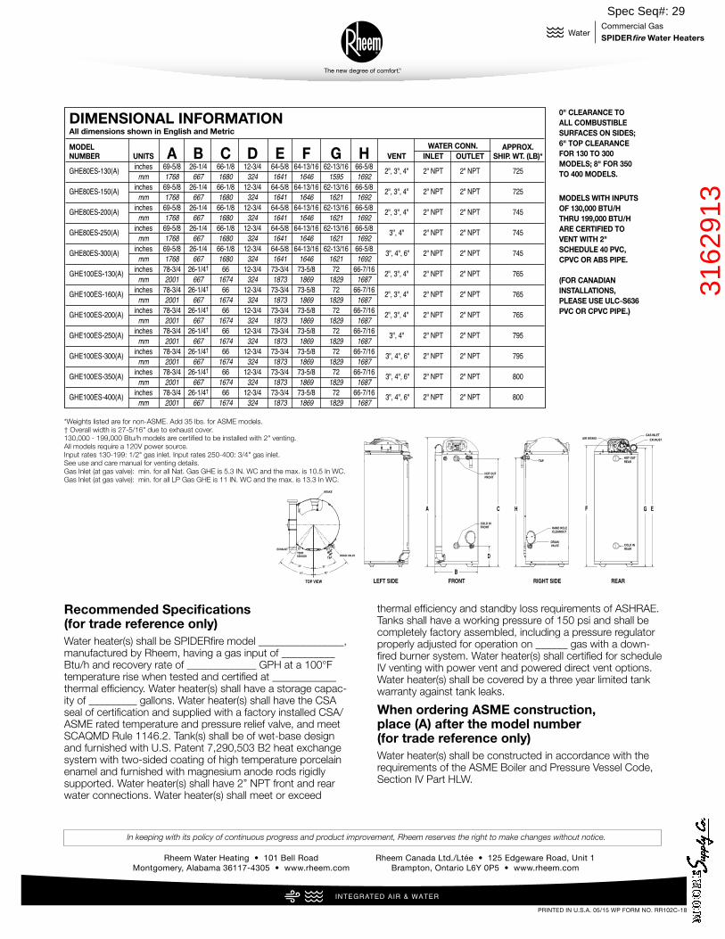
DIMENSIONAL INFORMATION All dimensions shown in English and Metric
MODEL WATER CONN. APPROX. NUMBER UNITS A B C D E F G H VENT INLET OUTLET SHIP. WT. (LB)*
GHE80ES-130(A) inches 69-5/8 26-1/4 66-1/8 12-3/4 64-5/8 64-13/16 62-13/16 66-5/8 2", 3", 4" 2" NPT 2" NPT 725 mm 1768 667 1680 324 1641 1646 1595 1692 GHE80ES-150(A) inches 69-5/8 26-1/4 66-1/8 12-3/4 64-5/8 64-13/16 62-13/16 66-5/8 2", 3", 4" 2" NPT 2" NPT 725 mm 1768 667 1680 324 1641 1646 1621 1692
GHE80ES-200(A) inches 69-5/8 26-1/4 66-1/8 12-3/4 64-5/8 64-13/16 62-13/16 66-5/8 2", 3", 4" 2" NPT 2" NPT 745 mm 1768 667 1680 324 1641 1646 1621 1692 GHE80ES-250(A) inches 69-5/8 26-1/4 66-1/8 12-3/4 64-5/8 64-13/16 62-13/16 66-5/8 3", 4" 2" NPT 2" NPT 745 mm 1768 667 1680 324 1641 1646 1621 1692 GHE80ES-300(A) inches 69-5/8 26-1/4 66-1/8 12-3/4 64-5/8 64-13/16 62-13/16 66-5/8 3", 4", 6" 2" NPT 2" NPT 745 mm 1768 667 1680 324 1641 1646 1621 1692
GHE100ES-130(A) inches 78-3/4 26-1/4† 66 12-3/4 73-3/4 73-5/8 72 66-7/16 2", 3", 4" 2" NPT 2" NPT 765 mm 2001 667 1674 324 1873 1869 1829 1687 GHE100ES-160(A) inches 78-3/4 26-1/4† 66 12-3/4 73-3/4 73-5/8 72 66-7/16 2", 3", 4" 2" NPT 2" NPT 765 mm 2001 667 1674 324 1873 1869 1829 1687 GHE100ES-200(A) inches 78-3/4 26-1/4† 66 12-3/4 73-3/4 73-5/8 72 66-7/16 2", 3", 4" 2" NPT 2" NPT 765 mm 2001 667 1674 324 1873 1869 1829 1687 GHE100ES-250(A) inches 78-3/4 26-1/4† 66 12-3/4 73-3/4 73-5/8 72 66-7/16 3", 4" 2" NPT 2" NPT 795 mm 2001 667 1674 324 1873 1869 1829 1687 GHE100ES-300(A) inches 78-3/4 26-1/4† 66 12-3/4 73-3/4 73-5/8 72 66-7/16 3", 4", 6" 2" NPT 2" NPT 795 mm 2001 667 1674 324 1873 1869 1829 1687 GHE100ES-350(A) inches 78-3/4 26-1/4† 66 12-3/4 73-3/4 73-5/8 72 66-7/16 3", 4", 6" 2" NPT 2" NPT 800 mm 2001 667 1674 324 1873 1869 1829 1687 GHE100ES-400(A) inches 78-3/4 26-1/4† 66 12-3/4 73-3/4 73-5/8 72 66-7/16 3", 4", 6" 2" NPT 2" NPT 800 mm 2001 667 1674 324 1873 1869 1829 1687
*Weights listed are for non-ASME. Add 35 lbs. for ASME models.130,000 - 199,000 Btu/h models are certified to be installed with 2" venting.All models require a 120V power source.Input rates 130-199: 1/2" gas inlet. Input rates 250-400: 3/4" gas inlet.See use and care manual for venting details.† Overall width is 27-5/16" due to exhaust cover.
0" CLEARANCE TO ALL COMBUSTIBLESURFACES ON SIDES;6" TOP CLEARANCEFOR 130 TO 300 MODELS; 8" FOR 350TO 400 MODELS.
MODELS WITH INPUTSOF 130,000 BTU/HTHRU 199,000 BTU/HARE CERTIFIED TOVENT WITH 2" SCHEDULE 40 PVC,CPVC OR ABS PIPE.
(FOR CANADIAN INSTALLATIONS,PLEASE USE ULC-S636PVC OR CPVC PIPE.)
A
B
D
C H GF E
COLD INFRONT
HOT OUTFRONT
DRAINVALVE
T&P
HAND HOLECLEANOUT
COLD INREAR
HOT OUTREAR
EXHAUSTAIR INTAKEGAS INLET
LEFT SIDE RIGHT SIDEFRONT REAR
31°
42°
31°
DRAIN VALVET&P
TEMPSENSOR
EXHAUST
INTAKE
TOP VIEW
41°
*Weights listed are for non-ASME. Add 35 lbs. for ASME models.† Overall width is 27-5/16" due to exhaust cover.130,000 - 199,000 Btu/h models are certified to be installed with 2" venting.All models require a 120V power source.Input rates 130-199: 1/2" gas inlet. Input rates 250-400: 3/4" gas inlet.See use and care manual for venting details. Gas Inlet (at gas valve): min. for all Nat. Gas GHE is 5.3 IN. WC and the max. is 10.5 In WC.Gas Inlet (at gas valve): min. for all LP Gas GHE is 11 IN. WC and the max. is 13.3 In WC.
PRINTED IN U.S.A. 05/15 WP FORM NO. RR102C-18 Rev. 9
4
In keeping with its policy of continuous progress and product improvement, Rheem reserves the right to make changes without notice.
Rheem Water Heating • 101 Bell Road Montgomery, Alabama 36117-4305 • www.rheem.com
Rheem Canada Ltd./Ltée • 125 Edgeware Road, Unit 1 Brampton, Ontario L6Y 0P5 • www.rheem.com
Water Commercial GasSPIDERfire Water Heaters
INTEGRATED AIR & WATERINTEGRATED HOME COMFORT
Recommended Specifications (for trade reference only)Water heater(s) shall be SPIDERfire model ________________, manufactured by Rheem, having a gas input of __________ Btu/h and recovery rate of _____________ GPH at a 100°F temperature rise when tested and certified at ____________ thermal efficiency. Water heater(s) shall have a storage capac-ity of _________ gallons. Water heater(s) shall have the CSA seal of certification and supplied with a factory installed CSA/ASME rated temperature and pressure relief valve, and meet SCAQMD Rule 1146.2. Tank(s) shall be of wet-base design and furnished with U.S. Patent 7,290,503 B2 heat exchange system with two-sided coating of high temperature porcelain enamel and furnished with magnesium anode rods rigidly supported. Water heater(s) shall have 2” NPT front and rear water connections. Water heater(s) shall meet or exceed
thermal efficiency and standby loss requirements of ASHRAE. Tanks shall have a working pressure of 150 psi and shall be completely factory assembled, including a pressure regulator properly adjusted for operation on ______ gas with a down-fired burner system. Water heater(s) shall certified for schedule IV venting with power vent and powered direct vent options. Water heater(s) shall be covered by a three year limited tank warranty against tank leaks.
When ordering ASME construction, place (A) after the model number (for trade reference only)Water heater(s) shall be constructed in accordance with the requirements of the ASME Boiler and Pressure Vessel Code, Section IV Part HLW.
Spec Seq#: 29
3162
913
Spec Seq#: 30
ET
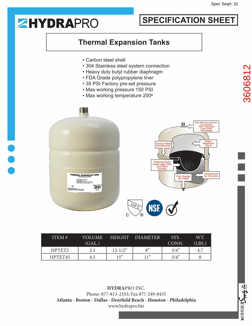
Thermal Expansion Tanks
• Carbon steel shell• 304 Stainless steel system connection• Heavy duty butyl rubber diaphragm • FDA Grade polypropylene liner• 35 PSI Factory pre-set pressure• Max working pressure 150 PSI• Max working temperature 2000
SPECIFICATION SHEET
HYDRAPRO INC.Phone: 877-813-2333; Fax 877-249-8435
Atlanta - Boston - Dallas - Deerfield Beach - Houston - Philadelphiawww.hydrapro.biz
ITEM # VOLUME (GAL.)
HEIGHT DIAMETER SYS. CONN.
WT. (LBS.)
HPTET2 2.1 12-1/2” 8” 3/4” 4.7HPTET45 4.5 15” 11” 3/4” 8
Spec Seq#: 31
3606
812
Spec Seq#: 32
FPHB
*WHEN ORDERING REPLACEMENT CARTRIDGE ASSEMBLY SPECIFY Y DIM.
Dimensional Data (inches and [ mm ]) are Subject to Manufacturing Tolerances and Change Without Notice
®
SPECIFICATION SHEET
TAG _______
ZURN INDUSTRIES, LLC. ♦♦♦♦♦ SPECIFICATION DRAINAGE OPERATION ♦♦♦♦♦ 1801 Pittsburgh Ave. ♦♦♦♦♦ Erie, PA 16514Phone: 814/455-0921 ♦♦♦♦♦ Fax: 814/454-7929 ♦♦♦♦♦ World Wide Web: www.zurn.com
In Canada: ZURN INDUSTRIES LIMITED ♦♦♦♦♦ 3544 Nashua Drive ♦♦♦♦♦ Mississauga, Ontario L4V1L2 ♦♦♦♦♦ Phone: 905/405-8272 Fax: 905/405-1292
OPTIONS (Check/specify appropriate options)
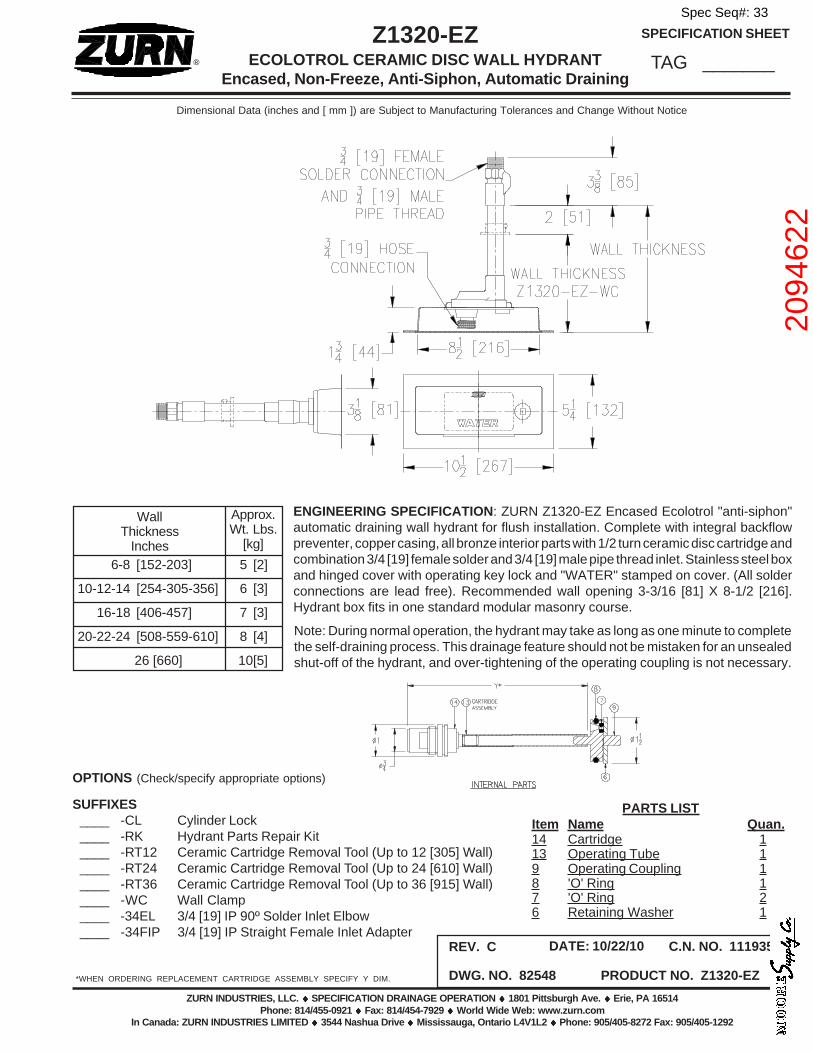
SUFFIXES____ -CL Cylinder Lock____ -RK Hydrant Parts Repair Kit____ -RT12 Ceramic Cartridge Removal Tool (Up to 12 [305] Wall)____ -RT24 Ceramic Cartridge Removal Tool (Up to 24 [610] Wall)____ -RT36 Ceramic Cartridge Removal Tool (Up to 36 [915] Wall)____ -WC Wall Clamp____ -34EL 3/4 [19] IP 90º Solder Inlet Elbow____ -34FIP 3/4 [19] IP Straight Female Inlet Adapter
Z1320-EZECOLOTROL CERAMIC DISC WALL HYDRANT
Encased, Non-Freeze, Anti-Siphon, Automatic Draining
PARTS LISTItem Name Quan.14 Cartridge 113 Operating Tube 19 Operating Coupling 18 'O' Ring 17 'O' Ring 26 Retaining Washer 1
DWG. NO. 82548 PRODUCT NO. Z1320-EZ
REV. C DATE: 10/22/10 C.N. NO. 111935
ENGINEERING SPECIFICATION: ZURN Z1320-EZ Encased Ecolotrol "anti-siphon"automatic draining wall hydrant for flush installation. Complete with integral backflowpreventer, copper casing, all bronze interior parts with 1/2 turn ceramic disc cartridge andcombination 3/4 [19] female solder and 3/4 [19] male pipe thread inlet. Stainless steel boxand hinged cover with operating key lock and "WATER" stamped on cover. (All solderconnections are lead free). Recommended wall opening 3-3/16 [81] X 8-1/2 [216].Hydrant box fits in one standard modular masonry course.
WallThickness
Inches6-8 [152-203] 5 [2]
10-12-14 [254-305-356] 6 [3]
16-18 [406-457] 7 [3]
20-22-24 [508-559-610] 8 [4]
26 [660] 10[5]
Approx.Wt. Lbs.
[kg]
Note: During normal operation, the hydrant may take as long as one minute to completethe self-draining process. This drainage feature should not be mistaken for an unsealedshut-off of the hydrant, and over-tightening of the operating coupling is not necessary.
Spec Seq#: 33
2094
622

Spec Seq#: 34
RH
©2012 WOODFORD Mfg. 0207
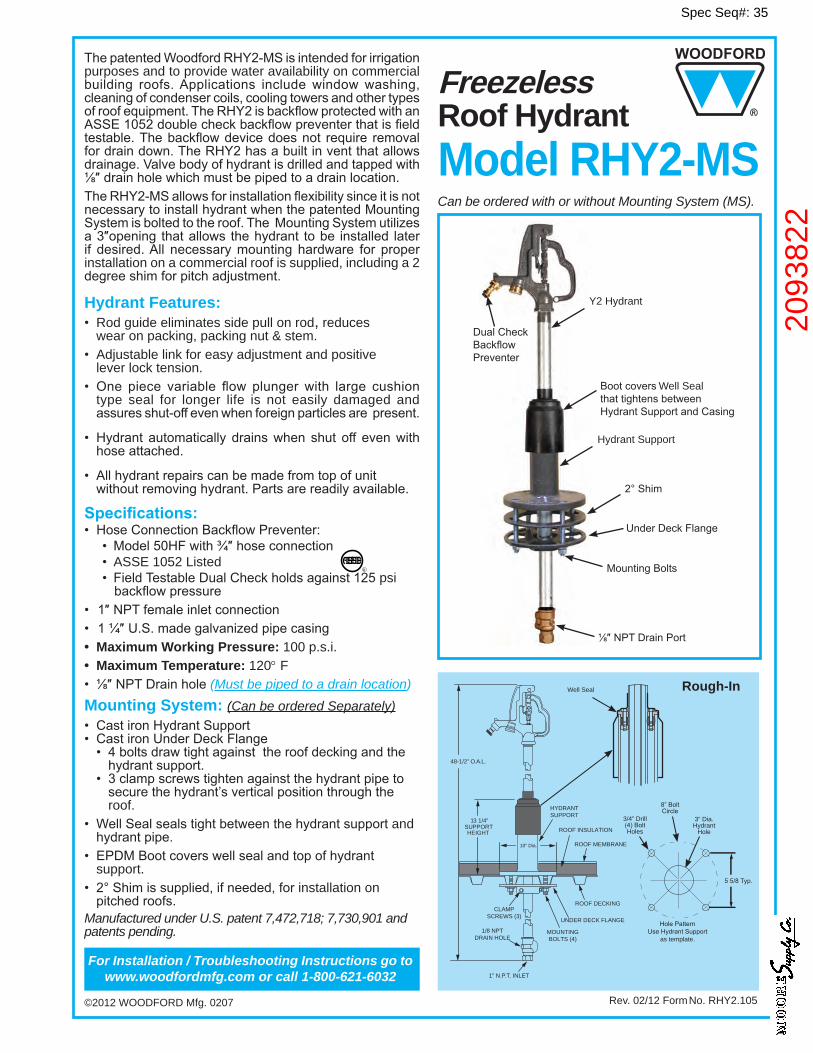
FreezelessRoof HydrantModel RHY2-MS
Rev. 02/12 Form No. RHY2.105
Hydrant Features:• Rod guide eliminates side pull on rod, reduces
wear on packing, packing nut & stem.• Adjustable link for easy adjustment and positive
lever lock tension.• One piece variable flow plungerwith large cushion
type seal for longer life is not easily damaged and assuresshut-offevenwhenforeignparticlesarepresent.
• Hydrant automatically drainswhen shut off evenwithhoseattached.
• Allhydrantrepairscanbemadefromtopofunit withoutremovinghydrant.Partsarereadilyavailable.
Specifications:•HoseConnectionBackflowPreventer:
• Model50HFwith¾″hoseconnection• ASSE 1052 Listed• FieldTestableDualCheckholdsagainst125psi backflowpressure
• 1″NPTfemaleinletconnection • 1¼″U.S.madegalvanizedpipecasing• Maximum Working Pressure: 100 p.s.i.• Maximum Temperature: 120° F• ⅛″NPTDrainhole(Must be piped to a drain location)Mounting System: (Can be ordered Separately)• CastironHydrantSupport• CastironUnderDeckFlange• 4boltsdrawtightagainsttheroofdeckingandthehydrantsupport.
• 3clampscrewstightenagainstthehydrantpipetosecurethehydrant’sverticalpositionthroughtheroof.
• WellSealsealstightbetweenthehydrantsupport and hydrantpipe.
• EPDMBootcoverswellsealandtopofhydrantsupport.
• 2°Shimissupplied,ifneeded,forinstallation on pitchedroofs.
Manufactured under U.S. patent 7,472,718; 7,730,901 and patents pending.
ThepatentedWoodfordRHY2-MSisintendedforirrigationpurposes and to provide water availability on commercial building roofs.Applications includewindowwashing,cleaningofcondensercoils,coolingtowersandothertypesofroofequipment.TheRHY2isbackflowprotectedwithanASSE1052doublecheckbackflowpreventerthatisfieldtestable.Thebackflowdevicedoesnot require removalfordraindown.TheRHY2hasabuiltinventthatallowsdrainage.Valvebodyofhydrantisdrilledandtappedwith⅛″drainholewhichmustbepipedtoadrainlocation.TheRHY2-MSallowsforinstallationflexibilitysinceitisnot necessarytoinstallhydrantwhenthepatentedMountingSystemisboltedtotheroof.TheMountingSystemutilizesa3″opening thatallows thehydrant tobe installed laterif desired.All necessarymounting hardware for properinstallation on a commercial roof is supplied, including a 2 degreeshimforpitchadjustment.
HolePatternUseHydrantSupport
as template.
3/4” Drill(4)BoltHoles
8”BoltCircle
3” Dia.Hydrant
Hole
Rough-In
48-1/2” O.A.L.
10” Dia.
ROOF DECKING
ROOF INSULATION
ROOF MEMBRANE
HYDRANTSUPPORT
CLAMPSCREWS (3)
1/8 NPTDRAIN HOLE
MOUNTINGBOLTS (4)
UNDER DECK FLANGE
1” N.P.T. INLET
13 1/4”SUPPORTHEIGHT
For Installation / Troubleshooting Instructions go to www.woodfordmfg.com or call 1-800-621-6032
Well Seal
Can be ordered with or without Mounting System (MS).
R
Bootcovers Well SealthattightensbetweenHydrantSupportandCasing
MountingBolts
⅛″NPTDrainPort
Hydrant Support
UnderDeckFlange
2°Shim
Y2 Hydrant
DualCheckBackflowPreventer
Spec Seq#: 35
2093
822
For more information contact...
2121WaynokaRoad,ColoradoSprings,Colorado80915 •Phone:(800)621-6032•Fax:(800)765-4115To view our complete product line visit: www.woodfordmfg.com or email: [email protected]
A Division Of WCM Industries, Inc.
WOODFORD MANUFACTURING COMPANY
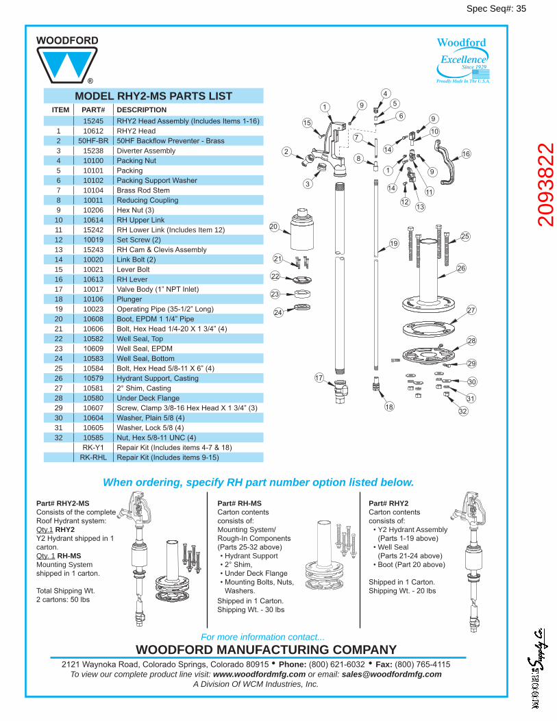
MODEL RHY2-MS PARTS LIST ITEM PART# DESCRIPTION
15245 RHY2HeadAssembly(IncludesItems1-16)1 10612 RHY2 Head2 50HF-BR 50HFBackflowPreventer-Brass3 15238 Diverter Assembly4 10100 PackingNut5 10101 Packing6 10102 PackingSupportWasher7 10104 BrassRodStem8 10011 ReducingCoupling9 10206 HexNut(3)
10 10614 RHUpperLink11 15242 RH Lower Link (Includes Item 12)12 10019 Set Screw (2) 13 15243 RHCam&ClevisAssembly14 10020 LinkBolt(2)15 10021 LeverBolt16 10613 RH Lever17 10017 ValveBody(1”NPTInlet)18 10106 Plunger19 10023 OperatingPipe(35-1/2”Long)20 10608 Boot,EPDM11/4”Pipe21 10606 Bolt,HexHead1/4-20X13/4”(4)22 10582 Well Seal, Top23 10609 WellSeal,EPDM24 10583 WellSeal,Bottom25 10584 Bolt,HexHead5/8-11X6”(4)26 10579 HydrantSupport,Casting27 10581 2°Shim,Casting28 10580 UnderDeckFlange29 10607 Screw,Clamp3/8-16HexHeadX13/4”(3)30 10604 Washer,Plain5/8(4)31 10605 Washer,Lock5/8(4)32 10585 Nut,Hex5/8-11UNC(4)
RK-Y1 RepairKit(Includesitems4-7&18)RK-RHL RepairKit(Includesitems9-15)
Part# RHY2-MS ConsistsofthecompleteRoofHydrantsystem:Qty.1 RHY2 Y2Hydrantshippedin1carton.Qty. 1 RH-MS Mounting System shippedin1carton.
TotalShippingWt.2cartons:50lbs
Part# RHY2 Cartoncontentsconsistsof:•Y2 Hydrant Assembly (Parts1-19above)
•Well Seal (Parts21-24above)
•Boot(Part20above)
Shippedin1Carton.ShippingWt.-20lbs
When ordering, specify RH part number option listed below.
Part# RH-MS Cartoncontentsconsistsof:Mounting System/Rough-InComponents(Parts25-32above)•Hydrant Support•2°Shim,•UnderDeckFlange•MountingBolts,Nuts, Washers.Shippedin1Carton.ShippingWt.-30lbs
Excellence
Woodford
Since 1929
Proudly Made In The U.S.A.
Spec Seq#: 35
2093
822