plug-and-play modules for flexible radiosynthesis
TRANSCRIPT
Applied Radiation and Isotopes 78 (2013) 113–124
Contents lists available at SciVerse ScienceDirect
Applied Radiation and Isotopes
0969-80http://d
n CorrSchool o
E-m1 Th
journal homepage: www.elsevier.com/locate/apradiso
Plug-and-play modules for flexible radiosynthesis
Henry Herman a,b,1, Graciela Flores a,b,1, Kevin Quinn a,b,1, Mark Eddings a,b,Sebastian Olma a,b, Melissa D. Moore a,b,c, Huijiang Ding a,b, Krzysztof P. Bobinski a,Mingwei Wang a,b, Dirk Williams a,b, Darin Wiliams a,b, Clifton Kwang-Fu Shen a,b,Michael E. Phelps a,b, R.Michael van Dama,b,n
a Crump Institute for Molecular Imaging, David Geffen School of Medicine, UCLA, Los Angeles, CA 90095, USAb Department of Molecular & Medical Pharmacology, David Geffen School of Medicine, UCLA, Los Angeles, CA, 90095, USAc Sofie Biosciences, Culver City, CA 90230, USA
H I G H L I G H T S
� A flexible, plug-and-play radiosynthesis platform based on modules was developed.
� Reaction, reagent delivery, and purification modules can be readily configured for diverse syntheses.� The reaction module is capable of high-pressure sealed reactions without solvent loss.� Any number of modules can be combined and controlled in a semi-automated fashion using a personal computer.� Syntheses of [18F]FDG, [18F]FNB, and D-[18F]FAC demonstrate versatility.a r t i c l e i n f o
Article history:Received 21 June 2012Received in revised form23 March 2013Accepted 13 April 2013Available online 25 April 2013
Keywords:Automated radiosynthesisHigh-pressure reactionsPETD-[18F]FACNucleoside analogsPlug-and-play reconfiguration
43/$ - see front matter & 2013 Elsevier Ltd. Ax.doi.org/10.1016/j.apradiso.2013.04.023
esponding author at: Crump Institute for Molf Medicine, UCLA, Los Angeles, CA 90095, USail address: [email protected] (R.Mese authors contributed equally to this work
a b s t r a c t
We present a plug-and-play radiosynthesis platform and accompanying computer software based onmodular subunits that can easily and flexibly be configured to implement a diverse range of radiosynthesisprotocols. Modules were developed that perform: (i) reagent storage and delivery, (ii) evaporations andsealed reactions, and (iii) cartridge-based purifications. The reaction module incorporates a simple roboticmechanism that removes tubing from the vessel and replaces it with a stopper prior to sealed reactions,enabling the system to withstand high pressures and thus provide tremendous flexibility in choice ofsolvents and temperatures. Any number of modules can rapidly be connected together using only a fewfluidic connections to implement a particular synthesis, and the resulting system is controlled in a semi-automated fashion by a single software interface. Radiosyntheses of 2-[18F]fluoro-2-deoxy-D-glucose ([18F]FDG), 1-[18F]fluoro-4-nitrobenzene ([18F]FNB), and 2′-deoxy-2′-[18F]fluoro-1-β-D-arabinofuranosyl cytosine(D-[18F]FAC) were performed to validate the system and demonstrate its versatility.
& 2013 Elsevier Ltd. All rights reserved.
1. Introduction
Increasing interest in several 18F-radiolabeled nucleoside analogprobes for positron emission tomography (PET) has created the needfor a radiosynthesizer for routine production that is capable of thechallenging synthesis conditions. Production of analogs such as 2′-deoxy-2′-[18F]fluoro-5-methyl-1-β-D-arabinofuranosyluracil ([18F]FMAU), 2′-deoxy-2′-[18F]fluoro-5-ethyl-1-β-D-arabinofuranosyluracil([18F]FEAU) (Shields, 2006; Vallabhajosula, 2007), and 1-(2′-deoxy-2′-[18F]fluoroarabinofuranosyl) cytosine ([18F]FAC) (Laing et al., 2009;Radu et al., 2008; Shu et al., 2010) involves reactions at hightemperatures in volatile solvents (and therefore high vapor
ll rights reserved.
ecular Imaging, David GeffenA. Tel.: +1 310 206 6507.ichael van Dam)..
pressures) to achieve sufficient yields for downstream imaging.Estimating from physical properties of the solvent (ChemicalEngineering Research Information Center (CHERIC), 2013, the [18F]FMAU synthesis reported by Mangner et al. (2003) involves apressure of 139 psig [957 kPag] during the coupling step (in chloro-form at 150 1C), and the D-[18F]FAC synthesis described by Radu et al.(2008) involves estimated pressures of 121 psig [834 kPag] duringfluorination (in acetonitrile at 165 1C) and 101 psig [695 kPag] duringthe coupling step (in 1,2-dichloroethane at 160 1C). In addition to theproduction of radiofluorinated nucleoside analogs, there is evidencethat the synthesis of other tracers can be improved by performingreactions at substantially higher temperatures and pressures thantypically used (Lu et al., 2009).
Since currently available radiosynthesizers are limited to heat-ing solvents not far above their boiling points (Ungersboeck et al.,2011), significant compromises in reaction conditions (such asreduced temperature or alternative solvents) are needed to adapt
H. Herman et al. / Applied Radiation and Isotopes 78 (2013) 113–124114
the above syntheses to automated platforms (Chin et al., 2007;Paolillo et al., 2009). Unfortunately, these changes and otherstrategies, such as milder synthesis pathways (Anderson et al.,2010; Li et al., 2011), seem to have an adverse effect on yield. Webelieve that the significant efforts that are generally spent tomodify radiochemistry to make it more amenable to automationin current systems should be balanced with efforts in making iteasier and more practical to work under more extreme conditions.To this end, we previously developed a first-generation reactionmodule (Amarasekera et al., this issue; Satyamurthy et al., 2010)capable of reliably performing sealed reactions at pressures up toat least 150 psig [1.03 MPag] without solvent loss. Addressing thefundamental source of limitations in other synthesizers, thismodule ensured all tubing was removed from the reaction vesseland replaced with a stopper during the high-pressure steps.
Though suitable for performing challenging syntheses withgood radiochemical yield, this reaction module was not auto-mated. For example, the robotic motions to manipulate the oilbath and stoppers were manually activated via switches on thecontroller, and liquid transfers and reagent additions were drivenmanually via syringes connected to tubing outside the hot cell. Inthis paper, we present a second-generation radiosynthesis plat-form consisting of several modules: an improved, more compact,version of the first-generation high-pressure reaction module, amodule for reagent storage and delivery, and a module forcartridge purification. With only a few fluidic connections requiredbetween them, any number of modules can be assembled in aplug-and-play fashion to implement a system with the necessarycapabilities for a wide range of different radiosyntheses. Theresulting system can immediately be operated via a user-friendlysoftware interface in a semi-automated fashion without anyconfiguration of the software. To demonstrate the performanceand versatility, 2-[18F]fluoro-2-deoxy-D-gluocise ([18F]FDG), 1-[18F]fluoro-4-nitrobenzene ([18F]FNB), and D-[18F]FAC were synthe-sized as model compounds.
2. Materials and methods
2.1. Synthesis apparatus
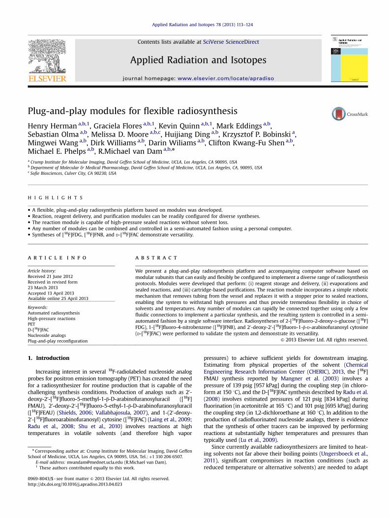
The radiosynthesis platform comprises three different types ofmodules that can be assembled to match the requirements (i.e.,number of vessels, number of reagents, and type of purificationsteps) of the intended radiosynthesis (Fig. 1). In addition to a
Fig. 1. Photographs of the PRM, RDM, and CPM modules and con
Pressurized Reaction Module (PRM) based on our previous work(Amarasekera et al., this issue), we have developed two additionalmodules: (i) a Reagent Delivery Module (RDM) for storing reagentsand delivering a selected reagent on demand to a reaction module,and (ii) a Cartridge Purification Module (CPM) for storing diluent,wash, and eluent solutions, and for delivering the crude sampleand these solutions on demand through a cartridge for purifica-tion. These additional modules reduce the need for manualintervention and thereby facilitate automation of syntheses requir-ing the high-pressure modules. By connecting modules in a plug-and-play fashion, diverse syntheses of varying complexity fromsingle-vessel syntheses such as [18F]FDG to multi-vessel synthesessuch as D-[18F]FAC can be readily implemented in a short time.
2.1.1. Pressurized reaction module (PRM)The PRM is designed to perform heated reactions under sealed
conditions as well as evaporations to remove solvent. The modulewas engineered to maintain seal integrity of reactions even at highpressures (at least 150 psig [1.0 MPag]), such as those generatedwhen reactions are performed in volatile organic solvents undersuper-heated conditions. Compatibility with high pressures isachieved by linearly translating the vial to one of three positions or“stations”. Each position is customized for a different step in thesynthesis protocol: a chemically-resistant “stopper” when sealedconditions are needed, and various tubing interfaces when otheroperations (reagent addition, transfer, evaporation) are needed(Fig. 2). With this mechanism, there are no valves or tubes exposedto the high-pressure vapor during sealed reactions. While our first-generation system (Amarasekera et al., this issue) exhibited repea-table and reliable performance in the hands of skilled radiochemists,we made a number of engineering modifications to enable thesystem to be moved into a variety of laboratory settings by providingincreased automation, modular construction, and greater flexibilityfor synthesis development. Furthermore, the system was miniatur-ized (decreased in height from 58 cm to 27 cm) to facilitate installa-tion in a mini-cell rather than a hot-cell. (Dimensions are27 cm�9.5 cm�27 cm height�width�depth.)
2.1.1.1. Reactor temperature control. The reaction vessel (Wheaton5 mL glass V-vial) is held within a chamber comprising analuminum jacket lined with a compressible thermally-conductivesilicone heat transfer material to ensure good thermal contact tothe vessel despite vial-to-vial size variation. Resistive heatingelements with feedback control and compressed air cooling
trollers. Note that some tubing has been omitted for clarity.
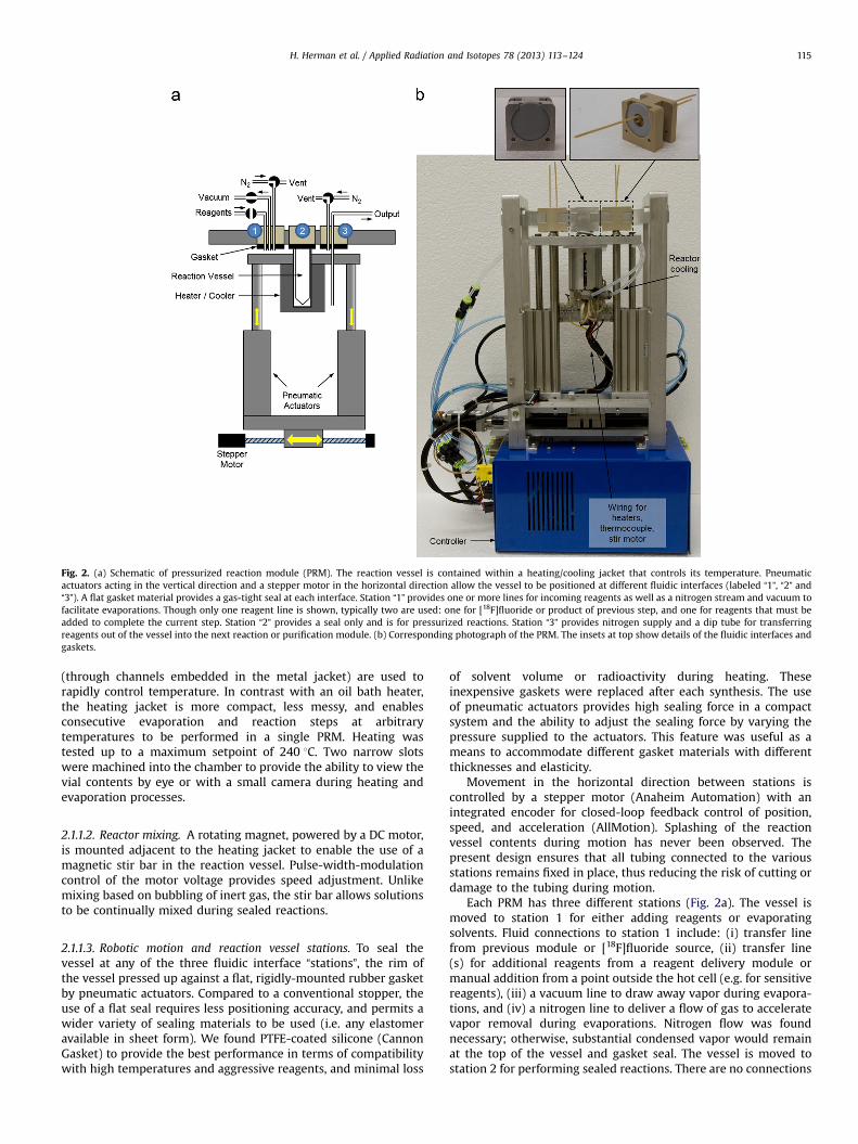
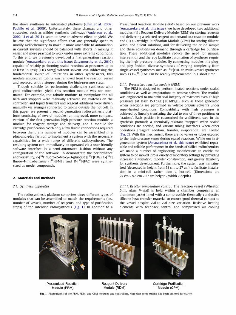
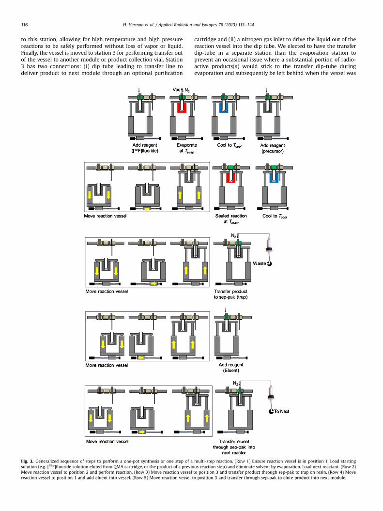
Fig. 2. (a) Schematic of pressurized reaction module (PRM). The reaction vessel is contained within a heating/cooling jacket that controls its temperature. Pneumaticactuators acting in the vertical direction and a stepper motor in the horizontal direction allow the vessel to be positioned at different fluidic interfaces (labeled “1”, “2” and“3”). A flat gasket material provides a gas-tight seal at each interface. Station “1” provides one or more lines for incoming reagents as well as a nitrogen stream and vacuum tofacilitate evaporations. Though only one reagent line is shown, typically two are used: one for [18F]fluoride or product of previous step, and one for reagents that must beadded to complete the current step. Station “2” provides a seal only and is for pressurized reactions. Station “3” provides nitrogen supply and a dip tube for transferringreagents out of the vessel into the next reaction or purification module. (b) Corresponding photograph of the PRM. The insets at top show details of the fluidic interfaces andgaskets.
H. Herman et al. / Applied Radiation and Isotopes 78 (2013) 113–124 115
(through channels embedded in the metal jacket) are used torapidly control temperature. In contrast with an oil bath heater,the heating jacket is more compact, less messy, and enablesconsecutive evaporation and reaction steps at arbitrarytemperatures to be performed in a single PRM. Heating wastested up to a maximum setpoint of 240 1C. Two narrow slotswere machined into the chamber to provide the ability to view thevial contents by eye or with a small camera during heating andevaporation processes.
2.1.1.2. Reactor mixing. A rotating magnet, powered by a DC motor,is mounted adjacent to the heating jacket to enable the use of amagnetic stir bar in the reaction vessel. Pulse-width-modulationcontrol of the motor voltage provides speed adjustment. Unlikemixing based on bubbling of inert gas, the stir bar allows solutionsto be continually mixed during sealed reactions.
2.1.1.3. Robotic motion and reaction vessel stations. To seal thevessel at any of the three fluidic interface “stations”, the rim ofthe vessel pressed up against a flat, rigidly-mounted rubber gasketby pneumatic actuators. Compared to a conventional stopper, theuse of a flat seal requires less positioning accuracy, and permits awider variety of sealing materials to be used (i.e. any elastomeravailable in sheet form). We found PTFE-coated silicone (CannonGasket) to provide the best performance in terms of compatibilitywith high temperatures and aggressive reagents, and minimal loss
of solvent volume or radioactivity during heating. Theseinexpensive gaskets were replaced after each synthesis. The useof pneumatic actuators provides high sealing force in a compactsystem and the ability to adjust the sealing force by varying thepressure supplied to the actuators. This feature was useful as ameans to accommodate different gasket materials with differentthicknesses and elasticity.
Movement in the horizontal direction between stations iscontrolled by a stepper motor (Anaheim Automation) with anintegrated encoder for closed-loop feedback control of position,speed, and acceleration (AllMotion). Splashing of the reactionvessel contents during motion has never been observed. Thepresent design ensures that all tubing connected to the variousstations remains fixed in place, thus reducing the risk of cutting ordamage to the tubing during motion.
Each PRM has three different stations (Fig. 2a). The vessel ismoved to station 1 for either adding reagents or evaporatingsolvents. Fluid connections to station 1 include: (i) transfer linefrom previous module or [18F]fluoride source, (ii) transfer line(s) for additional reagents from a reagent delivery module ormanual addition from a point outside the hot cell (e.g. for sensitivereagents), (iii) a vacuum line to draw away vapor during evapora-tions, and (iv) a nitrogen line to deliver a flow of gas to acceleratevapor removal during evaporations. Nitrogen flow was foundnecessary; otherwise, substantial condensed vapor would remainat the top of the vessel and gasket seal. The vessel is moved tostation 2 for performing sealed reactions. There are no connections
H. Herman et al. / Applied Radiation and Isotopes 78 (2013) 113–124116
to this station, allowing for high temperature and high pressurereactions to be safely performed without loss of vapor or liquid.Finally, the vessel is moved to station 3 for performing transfer outof the vessel to another module or product collection vial. Station3 has two connections: (i) dip tube leading to transfer line todeliver product to next module through an optional purification
Fig. 3. Generalized sequence of steps to perform a one-pot synthesis or one step of asolution (e.g. [18F]fluoride solution eluted from QMA cartridge, or the product of a previoMove reaction vessel to position 2 and perform reaction. (Row 3) Move reaction vesselreaction vessel to position 1 and add eluent into vessel. (Row 5) Move reaction vessel t
cartridge and (ii) a nitrogen gas inlet to drive the liquid out of thereaction vessel into the dip tube. We elected to have the transferdip-tube in a separate station than the evaporation station toprevent an occasional issue where a substantial portion of radio-active products(s) would stick to the transfer dip-tube duringevaporation and subsequently be left behind when the vessel was
multi-step reaction. (Row 1) Ensure reaction vessel is in position 1. Load startingus reaction step) and eliminate solvent by evaporation. Load next reactant. (Row 2)to position 3 and transfer product through sep-pak to trap on resin. (Row 4) Moveo position 3 and transfer through sep-pak to elute product into next module.
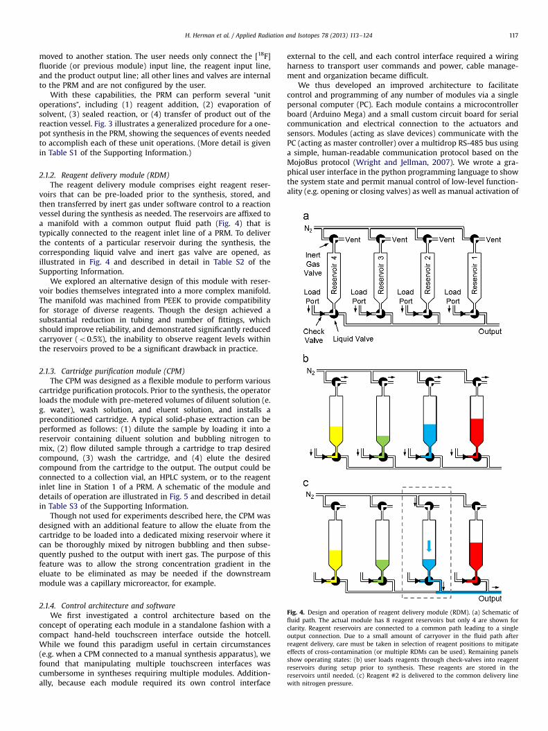
Fig. 4. Design and operation of reagent delivery module (RDM). (a) Schematic offluid path. The actual module has 8 reagent reservoirs but only 4 are shown forclarity. Reagent reservoirs are connected to a common path leading to a singleoutput connection. Due to a small amount of carryover in the fluid path afterreagent delivery, care must be taken in selection of reagent positions to mitigateeffects of cross-contamination (or multiple RDMs can be used). Remaining panelsshow operating states: (b) user loads reagents through check-valves into reagentreservoirs during setup prior to synthesis. These reagents are stored in thereservoirs until needed. (c) Reagent #2 is delivered to the common delivery linewith nitrogen pressure.
H. Herman et al. / Applied Radiation and Isotopes 78 (2013) 113–124 117
moved to another station. The user needs only connect the [18F]fluoride (or previous module) input line, the reagent input line,and the product output line; all other lines and valves are internalto the PRM and are not configured by the user.
With these capabilities, the PRM can perform several “unitoperations”, including (1) reagent addition, (2) evaporation ofsolvent, (3) sealed reaction, or (4) transfer of product out of thereaction vessel. Fig. 3 illustrates a generalized procedure for a one-pot synthesis in the PRM, showing the sequences of events neededto accomplish each of these unit operations. (More detail is givenin Table S1 of the Supporting Information.)
2.1.2. Reagent delivery module (RDM)The reagent delivery module comprises eight reagent reser-
voirs that can be pre-loaded prior to the synthesis, stored, andthen transferred by inert gas under software control to a reactionvessel during the synthesis as needed. The reservoirs are affixed toa manifold with a common output fluid path (Fig. 4) that istypically connected to the reagent inlet line of a PRM. To deliverthe contents of a particular reservoir during the synthesis, thecorresponding liquid valve and inert gas valve are opened, asillustrated in Fig. 4 and described in detail in Table S2 of theSupporting Information.
We explored an alternative design of this module with reser-voir bodies themselves integrated into a more complex manifold.The manifold was machined from PEEK to provide compatibilityfor storage of diverse reagents. Though the design achieved asubstantial reduction in tubing and number of fittings, whichshould improve reliability, and demonstrated significantly reducedcarryover (o0.5%), the inability to observe reagent levels withinthe reservoirs proved to be a significant drawback in practice.
2.1.3. Cartridge purification module (CPM)The CPM was designed as a flexible module to perform various
cartridge purification protocols. Prior to the synthesis, the operatorloads the module with pre-metered volumes of diluent solution (e.g. water), wash solution, and eluent solution, and installs apreconditioned cartridge. A typical solid-phase extraction can beperformed as follows: (1) dilute the sample by loading it into areservoir containing diluent solution and bubbling nitrogen tomix, (2) flow diluted sample through a cartridge to trap desiredcompound, (3) wash the cartridge, and (4) elute the desiredcompound from the cartridge to the output. The output could beconnected to a collection vial, an HPLC system, or to the reagentinlet line in Station 1 of a PRM. A schematic of the module anddetails of operation are illustrated in Fig. 5 and described in detailin Table S3 of the Supporting Information.
Though not used for experiments described here, the CPM wasdesigned with an additional feature to allow the eluate from thecartridge to be loaded into a dedicated mixing reservoir where itcan be thoroughly mixed by nitrogen bubbling and then subse-quently pushed to the output with inert gas. The purpose of thisfeature was to allow the strong concentration gradient in theeluate to be eliminated as may be needed if the downstreammodule was a capillary microreactor, for example.
2.1.4. Control architecture and softwareWe first investigated a control architecture based on the
concept of operating each module in a standalone fashion with acompact hand-held touchscreen interface outside the hotcell.While we found this paradigm useful in certain circumstances(e.g. when a CPM connected to a manual synthesis apparatus), wefound that manipulating multiple touchscreen interfaces wascumbersome in syntheses requiring multiple modules. Addition-ally, because each module required its own control interface
external to the cell, and each control interface required a wiringharness to transport user commands and power, cable manage-ment and organization became difficult.
We thus developed an improved architecture to facilitatecontrol and programming of any number of modules via a singlepersonal computer (PC). Each module contains a microcontrollerboard (Arduino Mega) and a small custom circuit board for serialcommunication and electrical connection to the actuators andsensors. Modules (acting as slave devices) communicate with thePC (acting as master controller) over a multidrop RS-485 bus usinga simple, human-readable communication protocol based on theMojoBus protocol (Wright and Jellman, 2007). We wrote a gra-phical user interface in the python programming language to showthe system state and permit manual control of low-level function-ality (e.g. opening or closing valves) as well as manual activation of
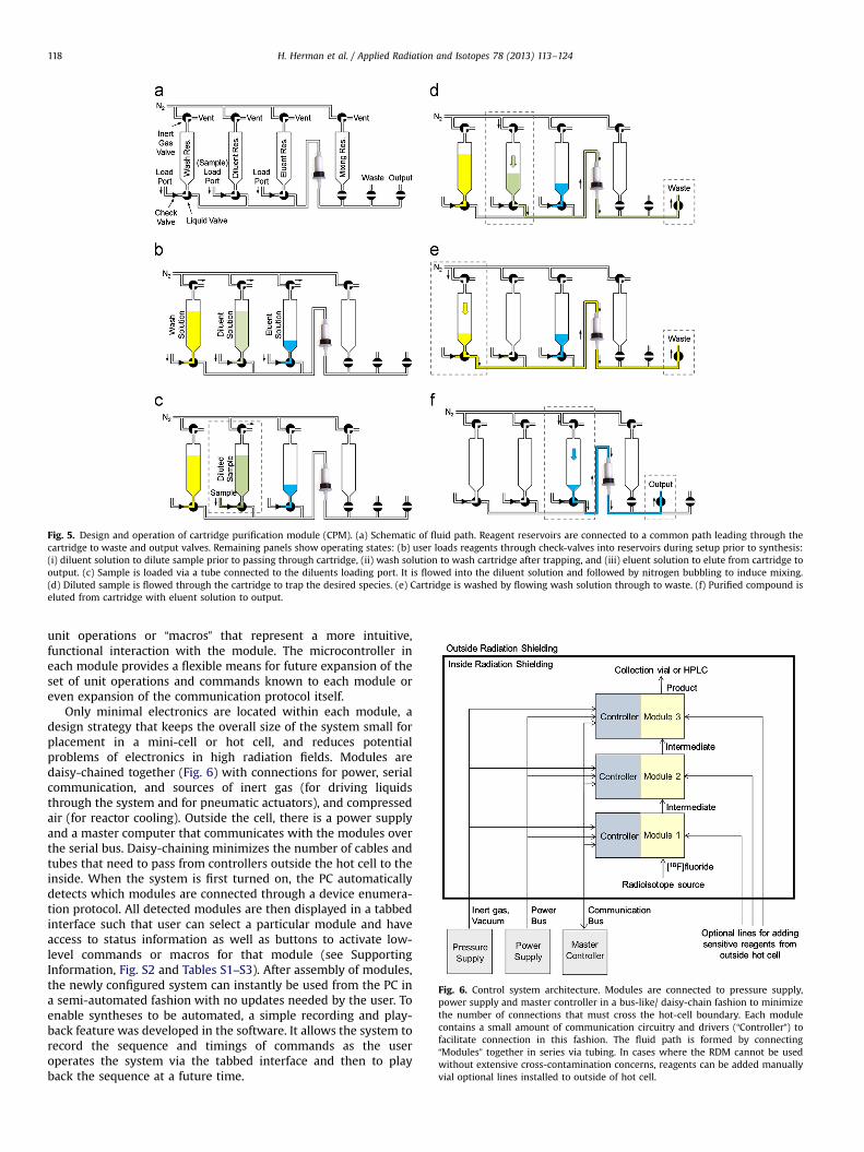
Fig. 5. Design and operation of cartridge purification module (CPM). (a) Schematic of fluid path. Reagent reservoirs are connected to a common path leading through thecartridge to waste and output valves. Remaining panels show operating states: (b) user loads reagents through check-valves into reservoirs during setup prior to synthesis:(i) diluent solution to dilute sample prior to passing through cartridge, (ii) wash solution to wash cartridge after trapping, and (iii) eluent solution to elute from cartridge tooutput. (c) Sample is loaded via a tube connected to the diluents loading port. It is flowed into the diluent solution and followed by nitrogen bubbling to induce mixing.(d) Diluted sample is flowed through the cartridge to trap the desired species. (e) Cartridge is washed by flowing wash solution through to waste. (f) Purified compound iseluted from cartridge with eluent solution to output.
Fig. 6. Control system architecture. Modules are connected to pressure supply,power supply and master controller in a bus-like/ daisy-chain fashion to minimizethe number of connections that must cross the hot-cell boundary. Each modulecontains a small amount of communication circuitry and drivers (“Controller”) tofacilitate connection in this fashion. The fluid path is formed by connecting“Modules” together in series via tubing. In cases where the RDM cannot be usedwithout extensive cross-contamination concerns, reagents can be added manuallyvial optional lines installed to outside of hot cell.
H. Herman et al. / Applied Radiation and Isotopes 78 (2013) 113–124118
unit operations or “macros” that represent a more intuitive,functional interaction with the module. The microcontroller ineach module provides a flexible means for future expansion of theset of unit operations and commands known to each module oreven expansion of the communication protocol itself.
Only minimal electronics are located within each module, adesign strategy that keeps the overall size of the system small forplacement in a mini-cell or hot cell, and reduces potentialproblems of electronics in high radiation fields. Modules aredaisy-chained together (Fig. 6) with connections for power, serialcommunication, and sources of inert gas (for driving liquidsthrough the system and for pneumatic actuators), and compressedair (for reactor cooling). Outside the cell, there is a power supplyand a master computer that communicates with the modules overthe serial bus. Daisy-chaining minimizes the number of cables andtubes that need to pass from controllers outside the hot cell to theinside. When the system is first turned on, the PC automaticallydetects which modules are connected through a device enumera-tion protocol. All detected modules are then displayed in a tabbedinterface such that user can select a particular module and haveaccess to status information as well as buttons to activate low-level commands or macros for that module (see SupportingInformation, Fig. S2 and Tables S1–S3). After assembly of modules,the newly configured system can instantly be used from the PC ina semi-automated fashion with no updates needed by the user. Toenable syntheses to be automated, a simple recording and play-back feature was developed in the software. It allows the system torecord the sequence and timings of commands as the useroperates the system via the tabbed interface and then to playback the sequence at a future time.
H. Herman et al. / Applied Radiation and Isotopes 78 (2013) 113–124 119
2.2. Radiosyntheses
2.2.1. ReagentsAnhydrous acetonitrile (99.8%), anhydrous dimethyl sulfoxide
(99.85%), anhydrous hexane (98%), anhydrous ethyl acetate (99.8%),hydrochloric acid (1 N), sodium methoxide (0.5 M in methanol),anhydrous 1,2-dichloroethane (99.8%), dichloromethane (99.5%),anhydrous toluene (99.8%), hydrobromic acid (33 wt% in aceticacid), ammonium acetate, ammonium phosphate monobasic, potas-sium carbonate, 4,7,13,16,21,24-hexaoxa-1,10-diazabicyclo[8.8.8]hexacosane (Kryptofix K222), 1-fluoro-4-nitrobenzene (non-radio-active reference standard for FNB), and 1,4-dinitrobenzene werepurchased from Sigma Aldrich. 1,3,4,6-tetra-O-acetyl-2-O-trifluoro-methanesulfonyl-beta-D-mannopyranose (mannose triflate), 2-O-[(trifluoromethyl)sulfonyl]-1,3,5-tri-O-benzoyl-α-D-ribofuranose andbis(trimethylsilyl)cytosine were purchased from ABX, Germany.The non-radioactive D-FAC reference standard was purchasedfrom Moravek Biochemicals and Radiochemicals Company (Brea,CA). All chemicals were used without further purification.
No-carrier-added [18F]fluoride was produced in an RDS-111cyclotron by proton bombardment of 18O-enriched water ([18O]H2O, Rotem, Inc.). After bombardment, before each synthesis, ∼20–1500 mCi of the target water is flowed through a QMA ionexchange cartridge (WAT023525, Waters Corporation) to trap the[18F]fluoride (with ∼99% efficiency). The QMA cartridge is pre-conditioned with 6 mL 1 M KHCO3 followed by 12 mL H2O anddried with nitrogen at 5 psig. The [18F]fluoride was then releasedfrom this cartridge by eluting with K2CO3 (1 mg in 0.4 mL H2O).
2.2.2. Chromatography and analytical methodsAnalytical high-performance liquid chromatography (HPLC)
was performed with a Smartline system (Knauer, Germany)comprised of a quaternary gradient HPLC pump, solvent degasser,and UV detector. UV absorption was monitored at 254 nm, andradioactivity was monitored with a gamma detector (PET Meta-bolite Detector, Bioscan, Inc., Washington, DC).
Semi-preparative HPLC was performed with a Knauer 501 HPLCpump, K2501 UV detector, and a B-FC-1000 flow-count gammadetector (Bioscan). Control and data acquisition were provided bya GINA system (Raytest USA, Inc., Wilmington, NC) and analysiswas performed with the GINA Star software (Raytest).
Thin layer chromatography (TLC) was performed on precoatedsilica gel plates (Baker-flexs IB2-F, J.T. Baker). TLC plates werescanned using a miniGITA Star radio-TLC scanner (Raytest). Data
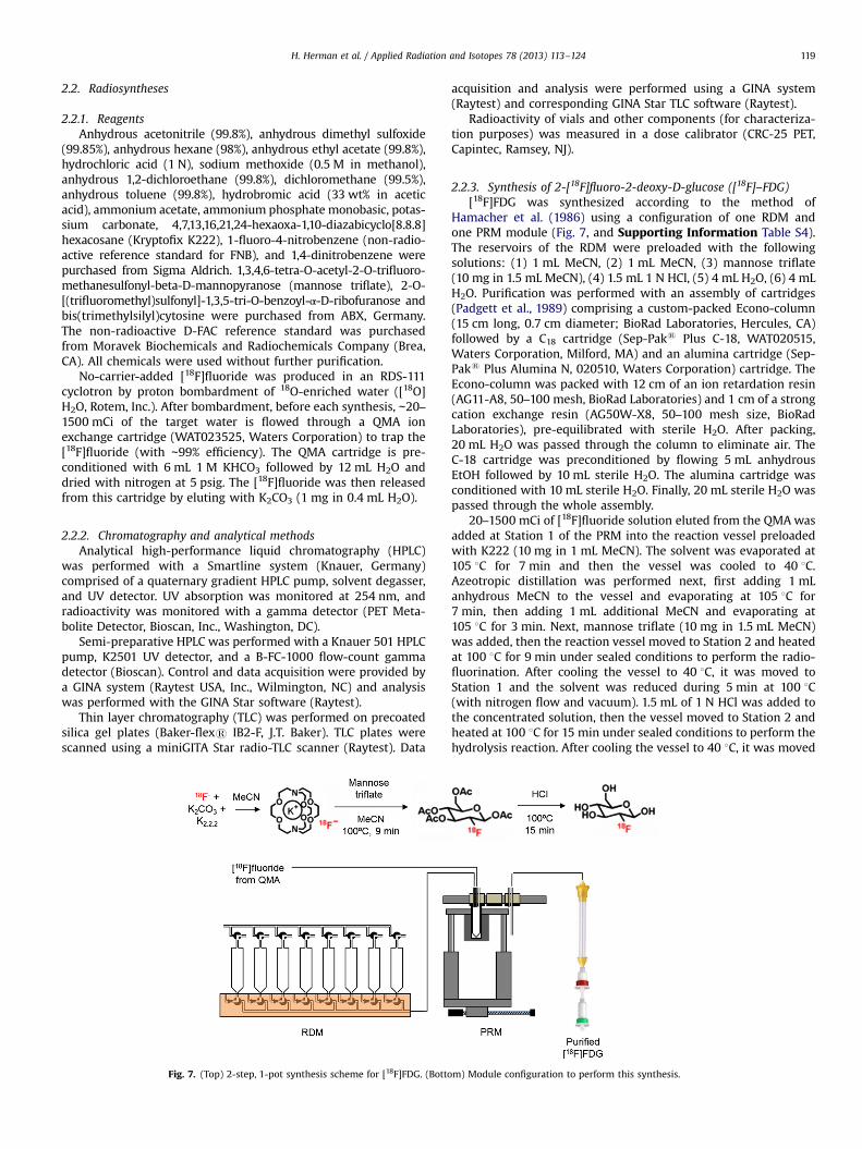
Fig. 7. (Top) 2-step, 1-pot synthesis scheme for [18F]FDG. (Botto
acquisition and analysis were performed using a GINA system(Raytest) and corresponding GINA Star TLC software (Raytest).
Radioactivity of vials and other components (for characteriza-tion purposes) was measured in a dose calibrator (CRC-25 PET,Capintec, Ramsey, NJ).
2.2.3. Synthesis of 2-[18F]fluoro-2-deoxy-D-glucose ([18F]–FDG)[18F]FDG was synthesized according to the method of
Hamacher et al. (1986) using a configuration of one RDM andone PRM module (Fig. 7, and Supporting Information Table S4).The reservoirs of the RDM were preloaded with the followingsolutions: (1) 1 mL MeCN, (2) 1 mL MeCN, (3) mannose triflate(10 mg in 1.5 mL MeCN), (4) 1.5 mL 1 N HCl, (5) 4 mL H2O, (6) 4 mLH2O. Purification was performed with an assembly of cartridges(Padgett et al., 1989) comprising a custom-packed Econo-column(15 cm long, 0.7 cm diameter; BioRad Laboratories, Hercules, CA)followed by a C18 cartridge (Sep-Paks Plus C-18, WAT020515,Waters Corporation, Milford, MA) and an alumina cartridge (Sep-Paks Plus Alumina N, 020510, Waters Corporation) cartridge. TheEcono-column was packed with 12 cm of an ion retardation resin(AG11-A8, 50–100 mesh, BioRad Laboratories) and 1 cm of a strongcation exchange resin (AG50W-X8, 50–100 mesh size, BioRadLaboratories), pre-equilibrated with sterile H2O. After packing,20 mL H2O was passed through the column to eliminate air. TheC-18 cartridge was preconditioned by flowing 5 mL anhydrousEtOH followed by 10 mL sterile H2O. The alumina cartridge wasconditioned with 10 mL sterile H2O. Finally, 20 mL sterile H2O waspassed through the whole assembly.
20–1500 mCi of [18F]fluoride solution eluted from the QMAwasadded at Station 1 of the PRM into the reaction vessel preloadedwith K222 (10 mg in 1 mL MeCN). The solvent was evaporated at105 1C for 7 min and then the vessel was cooled to 40 1C.Azeotropic distillation was performed next, first adding 1 mLanhydrous MeCN to the vessel and evaporating at 105 1C for7 min, then adding 1 mL additional MeCN and evaporating at105 1C for 3 min. Next, mannose triflate (10 mg in 1.5 mL MeCN)was added, then the reaction vessel moved to Station 2 and heatedat 100 1C for 9 min under sealed conditions to perform the radio-fluorination. After cooling the vessel to 40 1C, it was moved toStation 1 and the solvent was reduced during 5 min at 100 1C(with nitrogen flow and vacuum). 1.5 mL of 1 N HCl was added tothe concentrated solution, then the vessel moved to Station 2 andheated at 100 1C for 15 min under sealed conditions to perform thehydrolysis reaction. After cooling the vessel to 40 1C, it was moved
m) Module configuration to perform this synthesis.
H. Herman et al. / Applied Radiation and Isotopes 78 (2013) 113–124120
to Station 3 and the 1–2 mL of crude [18F]FDG was transferreddirectly into the assembly of purification cartridges. The radio-chemically pure [18F]FDG is flushed out of the assembly by theaddition and subsequent transfer of two portions of water(∼4.0 mL each) to the vessel. A small sample was taken for qualitycontrol. The radiochemical purity was confirmed by radio-TLC(mobile phase: MeCN:H2O, 95:5 v/v).
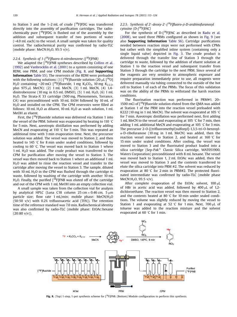
2.2.4. Synthesis of 1-[18F]fluoro-4-nitrobenzene ([18F]FNB)We adapted the [18F]FNB syntheses described by Collins et al.
(1992) and Vanbrocklin et al. (2001) to a system consisting of oneRDM, one PRM, and one CPM module (Fig. 8, and SupportingInformation Table S5). The reservoirs of the RDM were preloadedwith the following solutions: (1) [18F]fluoride solution (20 mL [18O]H2O containing ∼20 mCi [18F]fluoride, 1 mg K2CO3, 10 mg K2.2.2,plus 975 mL MeCN); (2) 1 mL MeCN, (3) 1 mL MeCN, (4) 1,4-dinitrobenzene (10 mg in 0.5 mL DMSO), (5) 1 mL H2O, (6) 1 mLH2O. The Strata-X 33 cartridge (500 mg, Phenomenex, Torrance,CA) was preconditioned with 10 mL EtOH followed by 10 mL ofH2O and installed on the CPM. The CPM reservoirs were filled asfollows: 10 mL H2O as diluent, 10 mL H2O as wash solution, 1 mLMeOH as eluent.
First, the [18F]fluoride solution was delivered via Station 1 intothe vessel of the PRM. Solvent was evaporated by heating to 110 1Cfor 5 min. Next, azeotropic distillation was performed by addingMeCN and evaporating at 110 1C for 5 min. This was repeated anadditional time with 3 min evaporation time. Next, the precursorsolution was added. The vessel was moved to Station 2, and thenheated to 145 1C for 8 min under sealed conditions, followed bycooling to 60 1C. The vessel was moved back to Station 1 where1 mL H2O was added. The crude product was transferred to theCPM for purification after moving the vessel to Station 3. Thevessel was then moved back to Station 1 where an additional 1 mLH2O was added to rinse the reaction vessel and transfer to thecartridge after moving the vessel to Station 3. The sample, dilutedwith 10 mL H2O in the CPM was flushed through the cartridge towaste, followed by washing of the cartridge with another 10 mLH2O. Finally, the purified [18F]FNB was eluted off of the cartridgeand out of the CPM with 1 mL MeOH into an empty collection vial.
A small sample was taken from the collection vial for analysisby analytical HPLC (Luna C18 column 25 cm�0.46 cm, 5 mmparticle size; flow rate 1 mL/min; mobile phase: MeCN/H2O(50:50 v/v) with 0.2% trifluoroacetic acid (TFA)). The retentiontime of the reference standard was 7.0 min. Radiochemical identitywas also confirmed by radio-TLC (mobile phase: EtOAc:hexane(20:80 v/v)).
Fig. 8. (Top) 1-step, 1-pot synthesis scheme for [18F]FNB. (B
2.2.5. Synthesis of 2′-deoxy-2′-[18F]fluoro-β-D-arabinofuranosylcytosine (D-[18F]FAC)
For the synthesis of D-[18F]FAC as described in Radu et al.(2008), we used three PRMs configured as shown in Fig. 9 (seealso Supporting Information Table S6). Cartridge purificationsneeded between reaction steps were not performed with CPMsbut rather with the simplified inline system (containing only asingle liquid valve) depicted in Fig. 3. The crude product isdelivered through the transfer line of Station 3 through thecartridge to waste, followed by the addition of eluent solution atStation 1 to the reaction vessel and subsequent transfer fromStation 3 through the cartridge to the next PRM. Since several ofthe reagents are very sensitive to atmospheric exposure andrequire preparation immediately prior to use, all reagents weredelivered manually via tubing connected to the outside of the hotcell to Station 1 of each of the PRMs. The focus of this validationwas on the ability of the PRMs to withstand the harsh reactionconditions.
The fluorination reaction was performed in PRM#1. 20–1500 mCi of [18F]fluoride solution eluted from the QMAwas addedat Station 1 of the PRM into the reaction vessel preloaded withK222 (10 mg in 1 mL MeCN). The solvent was evaporated at 105 1Cfor 7 min. Azeotropic distillation was performed next, first adding1 mL MeCN to the vessel and evaporating at 105 1C for 7 min, thenadding 1 mL additional MeCN and evaporating at 105 1C for 3 min.The precursor 2-O-[(trifluoromethyl)sulfonyl]-1,3,5-tri-O-benzoyl-α-D-ribofuranose (10 mg in 1 mL MeCN) was added, then thereaction vessel moved to Station 2, and heated at 160 1C for15 min under sealed conditions. After cooling, the vessel wasmoved to Station 3 and the fluorinated product loaded into asilica cartridge (Sep-Paks Classic Silica cartridge, WAT051900,Waters Corporation) preconditioned with 8 mL hexane. The vesselwas moved back to Station 1, 2 mL EtOAc was added, then thevessel was moved to Station 3 and the contents transferred toelute the silica cartridge into PRM #2. The solvent was reduced byevaporation at 80 1C for 2 min in PRM#2. The protected fluori-nated intermediate was confirmed by radio-TLC (mobile phaseMeCN:H2O, 95:5 v/v).
After complete evaporation of the EtOAc solvent, 100 mLof HBr in acetic acid was added, followed by 400 mL of 1,2-dichloroethane. The reaction vessel was then moved to Station 2,and the contents heated at 80 1C for 10 min under sealed condi-tions. The volume was slightly reduced by moving the vessel toStation 1 and evaporating at 52 1C for 1 min. Next, 700 mL oftoluene was added to the reaction mixture and the solventevaporated at 60 1C for 1 min.
ottom) Module configuration to perform this synthesis.
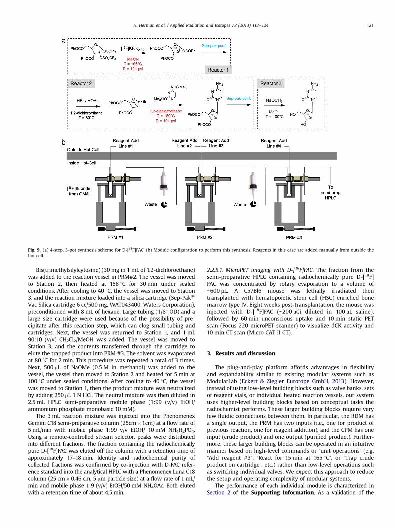
Fig. 9. (a) 4-step, 3-pot synthesis scheme for D-[18F]FAC. (b) Module configuration to perform this synthesis. Reagents in this case are added manually from outside thehot cell.
H. Herman et al. / Applied Radiation and Isotopes 78 (2013) 113–124 121
Bis(trimethylsilylcytosine) (30 mg in 1 mL of 1,2-dichloroethane)was added to the reaction vessel in PRM#2. The vessel was movedto Station 2, then heated at 158 1C for 30 min under sealedconditions. After cooling to 40 1C, the vessel was moved to Station3, and the reaction mixture loaded into a silica cartridge (Sep-Paks
Vac Silica cartridge 6 cc/500 mg, WAT043400, Waters Corporation),preconditioned with 8 mL of hexane. Large tubing (1/8″ OD) and alarge size cartridge were used because of the possibility of pre-cipitate after this reaction step, which can clog small tubing andcartridges. Next, the vessel was returned to Station 1, and 1 mL90:10 (v/v) CH2Cl2/MeOH was added. The vessel was moved toStation 3, and the contents transferred through the cartridge toelute the trapped product into PRM #3. The solvent was evaporatedat 80 1C for 2 min. This procedure was repeated a total of 3 times.Next, 500 mL of NaOMe (0.5 M in methanol) was added to thevessel, the vessel then moved to Station 2 and heated for 5 min at100 1C under sealed conditions. After cooling to 40 1C, the vesselwas moved to Station 1, then the product mixture was neutralizedby adding 250 mL 1 N HCl. The neutral mixture was then diluted in2.5 mL HPLC semi-preparative mobile phase (1:99 (v/v) EtOH/ammonium phosphate monobasic 10 mM).
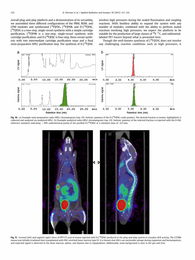
The 3 mL reaction mixture was injected into the PhenomenexGemini C18 semi-preparative column (25cm�1cm) at a flow rate of5 mL/min with mobile phase 1:99 v/v EtOH/ 10 mM NH4H2PO4.Using a remote-controlled stream selector, peaks were distributedinto different fractions. The fraction containing the radiochemicallypure D-[18F]FAC was eluted off the column with a retention time ofapproximately 17–18 min. Identity and radiochemical purity ofcollected fractions was confirmed by co-injection with D-FAC refer-ence standard into the analytical HPLC with a Phenomenex Luna C18column (25 cm�0.46 cm, 5 mm particle size) at a flow rate of 1 mL/min and mobile phase 1:9 (v/v) EtOH/50 mM NH4OAc. Both elutedwith a retention time of about 4.5 min.
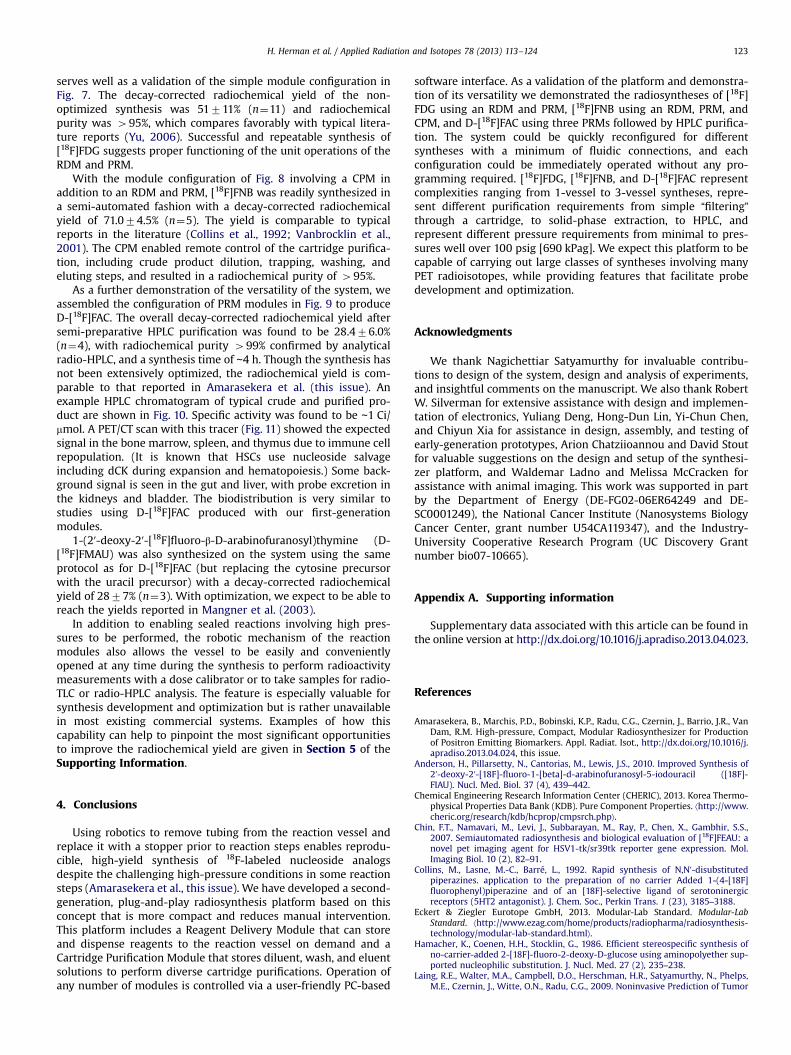
2.2.5.1. MicroPET imaging with D-[18F]FAC. The fraction from thesemi-preparative HPLC containing radiochemically pure D-[18F]FAC was concentrated by rotary evaporation to a volume of∼600 mL. A C57Bl6 mouse was lethally irradiated thentransplanted with hematopoietic stem cell (HSC) enriched bonemarrow type IV. Eight weeks post-transplantation, the mouse wasinjected with D-[18F]FAC (∼200 μCi diluted in 100 μL saline),followed by 60 min unconscious uptake and 10 min static PETscan (Focus 220 microPET scanner) to visualize dCK activity and10 min CT scan (Micro CAT II CT).
3. Results and discussion
The plug-and-play platform affords advantages in flexibilityand expandability similar to existing modular systems such asModularLab (Eckert & Ziegler Eurotope GmbH, 2013). However,instead of using low-level building blocks such as valve banks, setsof reagent vials, or individual heated reaction vessels, our systemuses higher-level building blocks based on conceptual tasks theradiochemist performs. These larger building blocks require veryfew fluidic connections between them. In particular, the RDM hasa single output, the PRM has two inputs (i.e., one for product ofprevious reaction, one for reagent addition), and the CPM has oneinput (crude product) and one output (purified product). Further-more, these larger building blocks can be operated in an intuitivemanner based on high-level commands or “unit operations” (e.g.“Add reagent #3”, “React for 15 min at 165 1C”, or “Trap crudeproduct on cartridge”, etc.) rather than low-level operations suchas switching individual valves. We expect this approach to reducethe setup and operating complexity of modular systems.
The performance of each individual module is characterized inSection 2 of the Supporting Information. As a validation of the
H. Herman et al. / Applied Radiation and Isotopes 78 (2013) 113–124122
overall plug-and-play platform and a demonstration of its versatility,we assembled three different configurations of the PRM, RDM, andCPM modules and synthesized [18F]FDG, [18F]FNB, and D-[18F]FAC.[18F]FDG is a two-step, single-vessel synthesis with a simple cartridgepurification, [18F]FNB is a one-step, single-vessel synthesis withcartridge purification, and D-[18F]FAC is four-step, three-vessel synth-esis with two intermediate cartridge purification steps and a finalsemi-preparative HPLC purification step. The synthesis of D-[18F]FAC
Fig. 10. (a) Example semi-preparative radio-HPLC chromatogram (top: UV; bottom: gamcollected and analyzed via analytical HPLC. (b) Example analytical radio-HPLC chromatoreference standard, indicating 499% radiochemical purity of the purified D-[18F]FAC at
Fig. 11. Coronal (left) and sagittal (right) slices of PET-CT scan of mouse injected with D-mouse was lethally irradiated then transplanted with HSC-enriched bone marrow type IVand expected signal is observed in the bone marrow, spleen, and thymus due to repop
involves high pressures during the sealed fluorination and couplingreactions. With limitless ability to expand the system with anynumber of modules, combined with the ability to perform sealedreactions involving high pressures, we expect the platform to besuitable for the production of large classes of 18F, 11C, and radiometal-labeled PET tracers beyond what is presented here.
Though the well-known synthesis of [18F]FDG does not involveany challenging reaction conditions such as high pressures, it
ma) of the D-[18F]FAC crude product. The desired fraction (β-isomer, highlighted) isgram (top: UV; bottom: gamma) of the selected fraction co-injected with the D-FACa retention time of ∼4.5 min.
[18F]FAC produced in the plug-and-play system to visualize dCK activity. The C57Bl6. It is known that HSCs use nucleoside salvage during expansion and hematopoiesis,ulation. Additionally, some background is seen in the gut and liver.
H. Herman et al. / Applied Radiation and Isotopes 78 (2013) 113–124 123
serves well as a validation of the simple module configuration inFig. 7. The decay-corrected radiochemical yield of the non-optimized synthesis was 51711% (n¼11) and radiochemicalpurity was 495%, which compares favorably with typical litera-ture reports (Yu, 2006). Successful and repeatable synthesis of[18F]FDG suggests proper functioning of the unit operations of theRDM and PRM.
With the module configuration of Fig. 8 involving a CPM inaddition to an RDM and PRM, [18F]FNB was readily synthesized ina semi-automated fashion with a decay-corrected radiochemicalyield of 71.074.5% (n¼5). The yield is comparable to typicalreports in the literature (Collins et al., 1992; Vanbrocklin et al.,2001). The CPM enabled remote control of the cartridge purifica-tion, including crude product dilution, trapping, washing, andeluting steps, and resulted in a radiochemical purity of 495%.
As a further demonstration of the versatility of the system, weassembled the configuration of PRM modules in Fig. 9 to produceD-[18F]FAC. The overall decay-corrected radiochemical yield aftersemi-preparative HPLC purification was found to be 28.476.0%(n¼4), with radiochemical purity 499% confirmed by analyticalradio-HPLC, and a synthesis time of ∼4 h. Though the synthesis hasnot been extensively optimized, the radiochemical yield is com-parable to that reported in Amarasekera et al. (this issue). Anexample HPLC chromatogram of typical crude and purified pro-duct are shown in Fig. 10. Specific activity was found to be ∼1 Ci/mmol. A PET/CT scan with this tracer (Fig. 11) showed the expectedsignal in the bone marrow, spleen, and thymus due to immune cellrepopulation. (It is known that HSCs use nucleoside salvageincluding dCK during expansion and hematopoiesis.) Some back-ground signal is seen in the gut and liver, with probe excretion inthe kidneys and bladder. The biodistribution is very similar tostudies using D-[18F]FAC produced with our first-generationmodules.
1-(2′-deoxy-2′-[18F]fluoro-β-D-arabinofuranosyl)thymine (D-[18F]FMAU) was also synthesized on the system using the sameprotocol as for D-[18F]FAC (but replacing the cytosine precursorwith the uracil precursor) with a decay-corrected radiochemicalyield of 2877% (n¼3). With optimization, we expect to be able toreach the yields reported in Mangner et al. (2003).
In addition to enabling sealed reactions involving high pres-sures to be performed, the robotic mechanism of the reactionmodules also allows the vessel to be easily and convenientlyopened at any time during the synthesis to perform radioactivitymeasurements with a dose calibrator or to take samples for radio-TLC or radio-HPLC analysis. The feature is especially valuable forsynthesis development and optimization but is rather unavailablein most existing commercial systems. Examples of how thiscapability can help to pinpoint the most significant opportunitiesto improve the radiochemical yield are given in Section 5 of theSupporting Information.
4. Conclusions
Using robotics to remove tubing from the reaction vessel andreplace it with a stopper prior to reaction steps enables reprodu-cible, high-yield synthesis of 18F-labeled nucleoside analogsdespite the challenging high-pressure conditions in some reactionsteps (Amarasekera et al., this issue). We have developed a second-generation, plug-and-play radiosynthesis platform based on thisconcept that is more compact and reduces manual intervention.This platform includes a Reagent Delivery Module that can storeand dispense reagents to the reaction vessel on demand and aCartridge Purification Module that stores diluent, wash, and eluentsolutions to perform diverse cartridge purifications. Operation ofany number of modules is controlled via a user-friendly PC-based
software interface. As a validation of the platform and demonstra-tion of its versatility we demonstrated the radiosyntheses of [18F]FDG using an RDM and PRM, [18F]FNB using an RDM, PRM, andCPM, and D-[18F]FAC using three PRMs followed by HPLC purifica-tion. The system could be quickly reconfigured for differentsyntheses with a minimum of fluidic connections, and eachconfiguration could be immediately operated without any pro-gramming required. [18F]FDG, [18F]FNB, and D-[18F]FAC representcomplexities ranging from 1-vessel to 3-vessel syntheses, repre-sent different purification requirements from simple “filtering”through a cartridge, to solid-phase extraction, to HPLC, andrepresent different pressure requirements from minimal to pres-sures well over 100 psig [690 kPag]. We expect this platform to becapable of carrying out large classes of syntheses involving manyPET radioisotopes, while providing features that facilitate probedevelopment and optimization.
Acknowledgments
We thank Nagichettiar Satyamurthy for invaluable contribu-tions to design of the system, design and analysis of experiments,and insightful comments on the manuscript. We also thank RobertW. Silverman for extensive assistance with design and implemen-tation of electronics, Yuliang Deng, Hong-Dun Lin, Yi-Chun Chen,and Chiyun Xia for assistance in design, assembly, and testing ofearly-generation prototypes, Arion Chatziioannou and David Stoutfor valuable suggestions on the design and setup of the synthesi-zer platform, and Waldemar Ladno and Melissa McCracken forassistance with animal imaging. This work was supported in partby the Department of Energy (DE-FG02-06ER64249 and DE-SC0001249), the National Cancer Institute (Nanosystems BiologyCancer Center, grant number U54CA119347), and the Industry-University Cooperative Research Program (UC Discovery Grantnumber bio07-10665).
Appendix A. Supporting information
Supplementary data associated with this article can be found inthe online version at http://dx.doi.org/10.1016/j.apradiso.2013.04.023.
References
Amarasekera, B., Marchis, P.D., Bobinski, K.P., Radu, C.G., Czernin, J., Barrio, J.R., VanDam, R.M. High-pressure, Compact, Modular Radiosynthesizer for Productionof Positron Emitting Biomarkers. Appl. Radiat. Isot., http://dx.doi.org/10.1016/j.apradiso.2013.04.024, this issue.
Anderson, H., Pillarsetty, N., Cantorias, M., Lewis, J.S., 2010. Improved Synthesis of2′-deoxy-2′-[18F]-fluoro-1-[beta]-d-arabinofuranosyl-5-iodouracil ([18F]-FIAU). Nucl. Med. Biol. 37 (4), 439–442.
Chemical Engineering Research Information Center (CHERIC), 2013. Korea Thermo-physical Properties Data Bank (KDB). Pure Component Properties. ⟨http://www.cheric.org/research/kdb/hcprop/cmpsrch.php⟩.
Chin, F.T., Namavari, M., Levi, J., Subbarayan, M., Ray, P., Chen, X., Gambhir, S.S.,2007. Semiautomated radiosynthesis and biological evaluation of [18F]FEAU: anovel pet imaging agent for HSV1-tk/sr39tk reporter gene expression. Mol.Imaging Biol. 10 (2), 82–91.
Collins, M., Lasne, M.-C., Barré, L., 1992. Rapid synthesis of N,N′-disubstitutedpiperazines. application to the preparation of no carrier Added 1-(4-[18F]fluorophenyl)piperazine and of an [18F]-selective ligand of serotoninergicreceptors (5HT2 antagonist). J. Chem. Soc., Perkin Trans. 1 (23), 3185–3188.
Eckert & Ziegler Eurotope GmbH, 2013. Modular-Lab Standard. Modular-LabStandard. ⟨http://www.ezag.com/home/products/radiopharma/radiosynthesis-technology/modular-lab-standard.html⟩.
Hamacher, K., Coenen, H.H., Stocklin, G., 1986. Efficient stereospecific synthesis ofno-carrier-added 2-[18F]-fluoro-2-deoxy-D-glucose using aminopolyether sup-ported nucleophilic substitution. J. Nucl. Med. 27 (2), 235–238.
Laing, R.E., Walter, M.A., Campbell, D.O., Herschman, H.R., Satyamurthy, N., Phelps,M.E., Czernin, J., Witte, O.N., Radu, C.G., 2009. Noninvasive Prediction of Tumor
H. Herman et al. / Applied Radiation and Isotopes 78 (2013) 113–124124
Responses to Gemcitabine Using Positron Emission Tomography. Proc. Natl.Acad. Sci. 106 (8), 2847–2852.
Li, Z., Cai, H., Conti, P.S., 2011. Automated Synthesis of 2′-deoxy-2′-[18F]fluoro-5-methyl-1-β-d-arabinofuranosyluracil ([18F]-FMAU) using a one reactor radio-synthesis module. Nucl. Med. Biol. 38 (2), 201–206.
Lu, S., Giamis, A.M., Pike, V.W., 2009. Synthesis of [18F]fallypride in a Micro-reactor:Rapid Optimization and Multiple-production in Small Doses for micro-PETStudies. Curr. Radiopharmaceuticals 2 (1), 1–13.
Mangner, T.J., Klecker, R.W., Anderson, L., Shields, A.F., 2003. Synthesis of 2′-deoxy-2′-[18F]fluoro-[beta]-D-arabinofuranosyl nucleosides, [18F]FAU, [18F]FMAU,[18F]FBAU and [18F]FIAU, as potential PET agents for imaging cellular prolifera-tion: synthesis of [18F]labelled FAU, FMAU, FBAU, FIAU. Nucl. Med. Biol. 30 (3),215–224.
Padgett, H.C., Schmidt, D.G., Luxen, A., Bida, G.T., Satyamurthy, N., Barrio, J.R., 1989.Computer-controlled radiochemical synthesis: a chemistry process control unitfor the automated production of radiochemicals. Int. J. Radiat. Appl. Instrum..Part A. Appl. Radiat. Isot. 40 (5), 433–445.
Paolillo, V., Riese, S., Gelovani, J.G., Alauddin, M.M., 2009. A fully automatedsynthesis of [18F]-FEAU and [18F]-FMAU using a novel dual reactor radio-synthesis module. J. Labelled Compd. Radiopharmaceuticals 52 (13), 553–558.
Radu, C.G., Shu, C.J., Nair-Gill, E., Shelly, S.M., Barrio, J.R., Satyamurthy, N., Phelps, M.E., Witte, O.N., 2008. Molecular imaging of lymphoid organs and immuneactivation using positron emission tomography with a new 18F-labeled 2′-deoxycytidine analog. Nat. Med. 14 (7), 783–788.
Satyamurthy, N., Barrio, J., Amarasekera, B., Van Dam, R.M., Olma, S., Williams, D.,Eddings, M., Shen, C., 2010. Modular Radiochemistry Synthesis System. Inter-national Patent Application WO/2010/021719.
Shields, A.F., 2006. Labeled pyrimidines in PET imaging. In: Valk, P.E., Delbeke, D.,Bailey, D.L., Townsend, D.W., Maisey, M.N. (Eds.), Positron Emission Tomogra-phy, 375–385. Springer, London.
Shu, C.J., Campbell, D.O., Lee, J.T., Tran, A.Q., Wengrod, J.C., Witte, O.N., Phelps, M.E.,Satyamurthy, N., Czernin, J., Radu, C.G., 2010. Novel PET probes specific fordeoxycytidine kinase. J. Nucl. Med. 51 (7), 1092–1098.
Ungersboeck, J., Philippe, C., Mien, L.-K., Haeusler, D., Shanab, K., Lanzenberger, R.,Spreitzer, H., et al., 2011. Microfluidic preparation of [18F]FE@SUPPY and [18F]FE@SUPPY:2—comparison with conventional radiosyntheses. Nucl. Med. Biol.38 (3), 427–434.
Vallabhajosula, S., 2007. 18F-labeled positron emission tomographic radiopharma-ceuticals in oncology: an overview of radiochemistry and mechanisms of tumorlocalization. Semin. Nucl. Med. 37 (6), 400–419.
Vanbrocklin, H.F., O’Neil, J.P., Hom, D.L., Gibbs, A.R., 2001. Synthesis of [18F]fluoroanilines: precursors to [18F]fluoroanilinoquinazolines. J. Labelled Compd.Radiopharmaceuticals 44 (S1), S880–S882.
Wright, E., Jellman, J.K., 2007. Beginner's Robotics on $50 a Month. SERVOMagazine, March.
Yu, S., 2006. Review of 18F-FDG synthesis and quality control. Biomed. ImagingIntervention J. 2 (4), e57.