“please hold the salt” - esaa.org · “please hold the salt” 2.2 human salt sources salts...
TRANSCRIPT
“Please Hold the Salt”
Reed Jackson, B.Sc.; AMEC Earth & Environmental
Randy Brunatti, A.Sc.T; AMEC Earth & Environmental
Gary Johnston, P.Geoph.; Cosmic Ventures
Maureen Johnston, P. Geol.; Cosmic Ventures
October 2005

“Please Hold the Salt”
TABLE OF CONTENTS PAGE
1.0 SALT IS NECESSARY – BUT TOO MUCH CAUSES HARM ...................................... 1
2.0 WHERE IS SALT FOUND IN ALBERTA ....................................................................... 1 2.1 NATURALLY OCCURING SALTS..................................................................... 1 2.2 Human Salt Sources................................................................................................ 3
2.2.1 Road Deicing .............................................................................................. 3 2.2.2 Industrial ..................................................................................................... 3 2.2.3 Oil and Gas Drilling and Production .......................................................... 3
3.0 WHO CARES ABOUT SALTY LAND AND WATER ................................................... 4 3.1 PUBLIC .................................................................................................................. 4 3.2 LANDOWNERS..................................................................................................... 5 3.3 REGULATORS ...................................................................................................... 5
4.0 HOW DID SALT GET OVER THERE AND HOW MUCH IS TOO MUCH ................. 6 4.1 OVERLAND FLOW .............................................................................................. 6 4.2 MIGRATION IN SOILS ........................................................................................ 7 4.3 GROUNDWATER FLOW..................................................................................... 7 4.4 OBSERVED ADVERSE EFFECTS ...................................................................... 8
5.0 HOW TO FIND AND DELINEATE SALT IMPACTS .................................................... 9 5.1 NONINTRUSIVE................................................................................................... 9
5.1.1 Historical Information................................................................................. 9 5.1.2 Vegetation Assessments.............................................................................. 9 5.1.3 Salt Spill Geophysics ................................................................................ 11
5.2 INTRUSIVE ......................................................................................................... 17 5.2.1 Soil Sampling............................................................................................ 17 5.2.2 Hydrogeologic Investigations ................................................................... 17
6.0 WHAT CAN YOU DO TO LIMIT OR REDUCE SALT IMPACTS ............................. 18 6.1 SPILL RESPONSE ON LAND............................................................................ 18 6.2 PROTECTION OF SURFACE WATER ............................................................. 19 6.3 DIG AND DUMP ................................................................................................. 20 6.4 SOIL AMENDMENTS ........................................................................................ 20 6.5 GROUNDWATER INTERCEPTION AND RECOVERY ................................. 21
6.5.1 Open Trench System................................................................................. 21 6.5.2 Shallow Tile Field..................................................................................... 21 6.5.3 Linear Groundwater Interceptor Trench ................................................... 24 6.5.4 Bored Wells .............................................................................................. 25 6.5.5 Keeping Things Running .......................................................................... 28
6.6 OTHER REMEDIATION METHODS ................................................................ 29
C:\Documents and Settings\Joe\Desktop\RemTech 2005 - PPT & Papers\Hydrocarbon & Salt Contamination\HydroSalt7.doc Page ii
“Please Hold the Salt”
TABLE OF CONTENTS (CONT'D) PAGE
7.0 CLOSURE ISSUES FOR SALTS TODAY AND IN THE FUTURE............................. 29 7.1 INDUSTRY .......................................................................................................... 29 7.2 LANDOWNERS................................................................................................... 30 7.3 OBTAINING SITE CLOSURE............................................................................ 30 7.4 RISK ASSESSMENT & SITE MANAGEMENT ............................................... 31 7.5 REGULATORY CHANGES................................................................................ 32
LIST OF TABLES PAGE
Table 1: Seawater Chemistry .................................................................................................4 Table 2: Regulatory Criteria and Guidelines for Salts in Soil and Water..............................6 Table 3: Saline Water Recovery Examples..........................................................................26
LIST OF PLATES PAGE
Plate 1: Naturally Saline Soils Around a Slough ..................................................................2 Plate 2: Surficial Salt Crust...................................................................................................8 Plate 3: Dead Stand of Treed in Salt Spill Area..................................................................10 Plate 4: Salt Stressed Leaves...............................................................................................10 Plate 5: EM 31 Survey ........................................................................................................12 Plate 6: EM 31 Anomaly – Deep Impacts...........................................................................14 Plate 7: EM 38 Anomaly – Shallow Impacts......................................................................15 Plate 8: Resistivity Psuedosections .....................................................................................16 Plate 9: Groundwater Chemistry Trend Analysis ...............................................................18 Plate 10: Installing Drainage Tiles........................................................................................22 Plate 11: Tile Field Layouts ..................................................................................................23 Plate 12: Root Plug Removed from Tile (>100 m long).......................................................23 Plate 13: Groundwater Interceptor and Recovery Trench ....................................................24 Plate 14: Bored Recovery Well.............................................................................................25 Plate 15: Decreasing EM Intensity After Two Recovery Seasons........................................26 Plate 16: Groundwater Recovery Record..............................................................................27 Plate 17: Groundwater Plume Reduction..............................................................................27 Plate 18: Calcium, Iron Oxide and Magnetite Crystal Scale on Groundwater Pump...........28 Plate 19: Soil Too Saline for Risk Assessment / Site Management Options........................32
C:\Documents and Settings\Joe\Desktop\RemTech 2005 - PPT & Papers\Hydrocarbon & Salt Contamination\HydroSalt7.doc Page iii
“Please Hold the Salt”
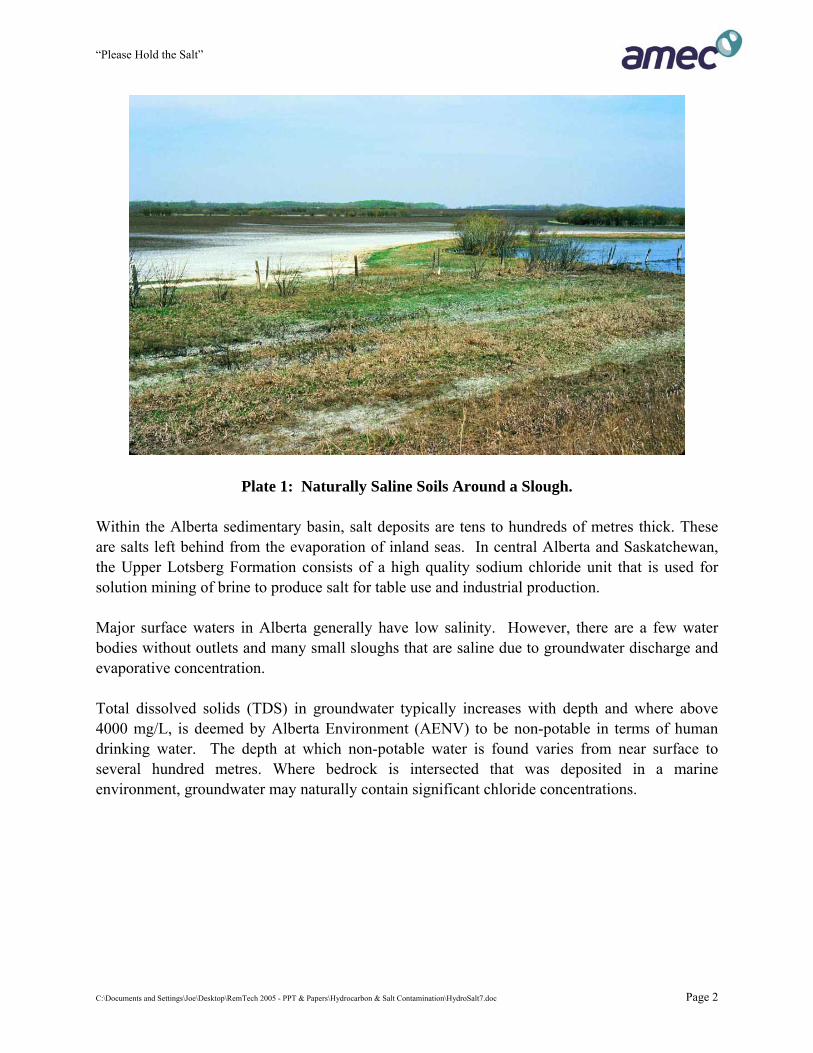
1.0 SALT IS NECESSARY – BUT TOO MUCH CAUSES HARM Sodium chloride or “salt” is essential to human and animal health. These two ions are responsible for regulating water balance, pH, and osmotic pressure; preserving acid-base balance in the body, aiding potassium absorption, supplying the essence of digestive stomach acid, and enhancing the ability of the blood to carry carbon dioxide from respiring tissues to the lungs. Most of us like or crave salty foods and animals are drawn to salt sources. However, too much salt in food or drinking water may result in high blood pressure and other health effects. Other “salt” compounds are also in use but to a much lesser extent then sodium chloride. These compounds include calcium chloride (dust suppressant, fill fluid for heavy equipment tires), potassium chloride (fertilizer, kill fluid for gas wells) and magnesium chloride (road deicer). Many plants tolerate some level of salt, but only a few plants (euhalophytes) require a highly saline setting to grow and reproduce. Some plants tolerate very little salt and are harmed at relatively low concentrations. This paper explores natural and human based salt issues in Alberta. Where salts have been released by human activities at concentrations capable of causing harm, site assessment and remediation actions are required. 2.0 WHERE IS SALT FOUND IN ALBERTA 2.1 NATURALLY OCCURING SALTS Naturally occurring salts are found throughout Alberta but are most common in solonetzic soils in southern Alberta. Due to evapotranspiration processes and / or irrigation, salts usually comprised of sodium or calcium sulphate accumulate within the growing layer. In other parts of Alberta, groundwater discharge may result in saline soils in coulee bottoms, around sloughs (Plate 1) and other depressions. Soils resulting from weathering of shallow sodium rich (sodic) bedrock or glacial till with high bedrock content may also be naturally saline. Naturally saline soils in Alberta rarely contain significant concentrations of chloride.
C:\Documents and Settings\Joe\Desktop\RemTech 2005 - PPT & Papers\Hydrocarbon & Salt Contamination\HydroSalt7.doc Page 1
“Please Hold the Salt”
Plate 1: Naturally Saline Soils Around a Slough. Within the Alberta sedimentary basin, salt deposits are tens to hundreds of metres thick. These are salts left behind from the evaporation of inland seas. In central Alberta and Saskatchewan, the Upper Lotsberg Formation consists of a high quality sodium chloride unit that is used for solution mining of brine to produce salt for table use and industrial production. Major surface waters in Alberta generally have low salinity. However, there are a few water bodies without outlets and many small sloughs that are saline due to groundwater discharge and evaporative concentration. Total dissolved solids (TDS) in groundwater typically increases with depth and where above 4000 mg/L, is deemed by Alberta Environment (AENV) to be non-potable in terms of human drinking water. The depth at which non-potable water is found varies from near surface to several hundred metres. Where bedrock is intersected that was deposited in a marine environment, groundwater may naturally contain significant chloride concentrations.
C:\Documents and Settings\Joe\Desktop\RemTech 2005 - PPT & Papers\Hydrocarbon & Salt Contamination\HydroSalt7.doc Page 2
“Please Hold the Salt”
2.2 Human Salt Sources Salts are produced and used for a variety of purposes beyond salt for our table or for livestock production. Some salts are purposely released into the environment - others are accidentally released. 2.2.1 Road Deicing Sodium chloride is mixed in varying concentrations with sand or fine gravel to make “pickled sand”. This mixture is spread on municipal roadways and highways and runs off with melted snow to roadside ditches and into the water shed. In major cities in Alberta, snow removed from streets is stored in lined sites to contain and control meltwater. Although approximately five million metric tonnes of salt are used on Canadian roads each year, it is spread over a large area. For the most part, salt impacts from road deicing are localized near roadways and snow dumps. Although these settings are usually not particularly sensitive, increasing salt concentrations in soil and groundwater have been observed. Salt impacts at historical pickled sand storage yards are another matter. These sites often stored nearly pure salt and salty sand mixtures outside over a period of decades. Soil and groundwater beneath and downgradient of these sites are often intensely saline. Impacts may extend more than a kilometre and are known to have affected residential drinking water supplies. 2.2.2 Industrial In Alberta, three primary industries produce salt from the Upper Lotsberg Formation. These include producers of salt for sale, producers that use salt for chemical processes and salt mining for the purpose of creating a cavern for storage of hydrocarbons. Some caverns are also used for waste disposal. As the storage, transport and disposal of salts and saline wastes is imperfect, salts have been released into soil, surface water and groundwater from storage pads, pipelines, tanks and brine ponds. Releases of pure salt, saturated brine or highly saline wastes have the potential to cause severe impacts that if not contained can affect soil and water resources hundreds of metres downgradient of the release site. 2.2.3 Oil and Gas Drilling and Production Oil and gas drilling and production operations take place at tens of thousands of locations across Western Canada. At most of these sites, water is produced along with the hydrocarbons. The ratio of water to oil and gas is highly variable from field to field and is related to the production age of the field. New wells may produce little water while old wells may produce 99 % water.
C:\Documents and Settings\Joe\Desktop\RemTech 2005 - PPT & Papers\Hydrocarbon & Salt Contamination\HydroSalt7.doc Page 3
“Please Hold the Salt”
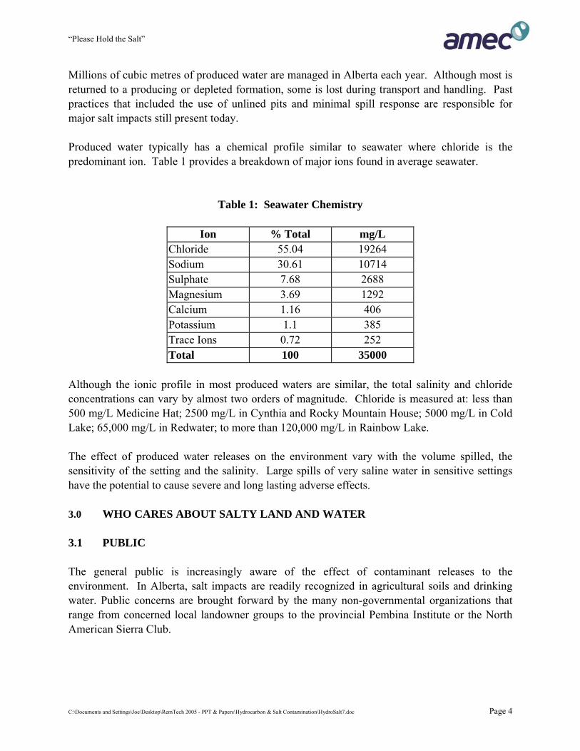
Millions of cubic metres of produced water are managed in Alberta each year. Although most is returned to a producing or depleted formation, some is lost during transport and handling. Past practices that included the use of unlined pits and minimal spill response are responsible for major salt impacts still present today. Produced water typically has a chemical profile similar to seawater where chloride is the predominant ion. Table 1 provides a breakdown of major ions found in average seawater.
Table 1: Seawater Chemistry
Ion % Total mg/L
Chloride 55.04 19264 Sodium 30.61 10714 Sulphate 7.68 2688 Magnesium 3.69 1292 Calcium 1.16 406 Potassium 1.1 385 Trace Ions 0.72 252 Total 100 35000
Although the ionic profile in most produced waters are similar, the total salinity and chloride concentrations can vary by almost two orders of magnitude. Chloride is measured at: less than 500 mg/L Medicine Hat; 2500 mg/L in Cynthia and Rocky Mountain House; 5000 mg/L in Cold Lake; 65,000 mg/L in Redwater; to more than 120,000 mg/L in Rainbow Lake. The effect of produced water releases on the environment vary with the volume spilled, the sensitivity of the setting and the salinity. Large spills of very saline water in sensitive settings have the potential to cause severe and long lasting adverse effects. 3.0 WHO CARES ABOUT SALTY LAND AND WATER 3.1 PUBLIC The general public is increasingly aware of the effect of contaminant releases to the environment. In Alberta, salt impacts are readily recognized in agricultural soils and drinking water. Public concerns are brought forward by the many non-governmental organizations that range from concerned local landowner groups to the provincial Pembina Institute or the North American Sierra Club.
C:\Documents and Settings\Joe\Desktop\RemTech 2005 - PPT & Papers\Hydrocarbon & Salt Contamination\HydroSalt7.doc Page 4
“Please Hold the Salt”
3.2 LANDOWNERS Although not always the case, salt releases from industrial properties often affect relatively insensitive adjacent landowners. On the other hand, salt releases from oil and gas properties are often on leased lands and are usually in agricultural or forest settings. With the increase in Alberta population and urban sprawl, residences now surround many oil and gas sites - or the former lease is included in the subdivision. Agricultural and residential land uses are very sensitive to residual salts and other contaminants from industrial activities. 3.3 REGULATORS Federal and Provincial regulators have the responsibility to protect the environment from adverse effects. Both bodies have established criteria for salinity in soil and water. These criteria vary with the setting and land use. The most stringent criteria apply to surface water or for sites with low background salinity that is in agricultural or residential land use. In Alberta, the principle of equivalent land use applies at the time of lease reclamation or spill remediation. If for example, the land is used to grow sensitive plants (e.g. strawberries, aspen, spruce); this may require a more stringent remediation target then the published criteria. This was often not the case historically when spill cleanup from oil and gas operations was solely the responsibility of the ERCB (now EUB). Past practices for produced water releases was usually premised on driving the salts down just far enough to allow something green to grow at surface. Where the salt mass was large, this approach was often only successful temporarily as the salts often came back to surface during dry periods or migrated laterally / vertically and appeared somewhere else. Key regulatory publications include: 1. Alberta Environment: Salt Contamination Assessment and Remediation Guidelines, 2001. 2. Alberta Environment: Surface Water Quality Guidelines for Use in Alberta, 1999. 3. Alberta Agriculture: Soil Quality Criteria Relative to Disturbance and Reclamation, 1987. 4. Alberta Agriculture: Salt Tolerance of Plants, 2001. 5. Environment Canada - CCME: Environmental Quality Guidelines, 1999 (as updated). 6. Environment Canada: Code of Practice for the Environmental Management of Road Salts,
2004. 7. Bight, A and Addison, J: Derivation of Matrix Soil Standards for Salt Under the British
Columbia Contaminated Sites Regulation, Royal Roads University, June 2002.
C:\Documents and Settings\Joe\Desktop\RemTech 2005 - PPT & Papers\Hydrocarbon & Salt Contamination\HydroSalt7.doc Page 5
“Please Hold the Salt”
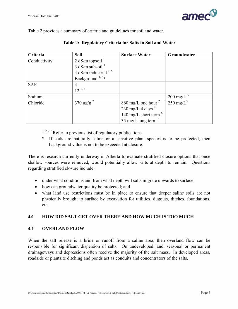
Table 2 provides a summary of criteria and guidelines for soil and water.
Table 2: Regulatory Criteria for Salts in Soil and Water Criteria Soil Surface Water Groundwater Conductivity 2 dS/m topsoil 1
3 dS/m subsoil 1
4 dS/m industrial 1, 5
Background 1, 3*
SAR 4 1
12 1, 5
Sodium 200 mg/L 5
Chloride 370 ug/g 7 860 mg/L one hour 2
230 mg/L 4 days 2
140 mg/L short term 6
35 mg/L long term 6
250 mg/L5
1, 2, - 7 Refer to previous list of regulatory publications * If soils are naturally saline or a sensitive plant species is to be protected, then
background value is not to be exceeded at closure. There is research currently underway in Alberta to evaluate stratified closure options that once shallow sources were removed, would potentially allow salts at depth to remain. Questions regarding stratified closure include:
• under what conditions and from what depth will salts migrate upwards to surface; • how can groundwater quality be protected; and • what land use restrictions must be in place to ensure that deeper saline soils are not
physically brought to surface by excavation for utilities, dugouts, ditches, foundations, etc.
4.0 HOW DID SALT GET OVER THERE AND HOW MUCH IS TOO MUCH 4.1 OVERLAND FLOW When the salt release is a brine or runoff from a saline area, then overland flow can be responsible for significant dispersion of salts. On undeveloped land, seasonal or permanent drainageways and depressions often receive the majority of the salt mass. In developed areas, roadside or plantsite ditching and ponds act as conduits and concentrators of the salts.
C:\Documents and Settings\Joe\Desktop\RemTech 2005 - PPT & Papers\Hydrocarbon & Salt Contamination\HydroSalt7.doc Page 6
“Please Hold the Salt”
4.2 MIGRATION IN SOILS Soil texture and permeability have a big influence on how salts move into and through soils. Fluid releases into sandy soils typically move rapidly downward a few metres to tens of metres until a low permeability barrier is reached. In clayey or frozen soils, fluid spills spread out and the initial penetration depth may be less than a metre. Clayey soils also exchange calcium and magnesium for sodium. This results in an increase in the sodium adsorption ratio (SAR) and can cause hardening of the soil and reduction in permeability in the rooting zone. Salts may also move vertically in the soil profile due to hydraulic forces. Rain and snowmelt infiltration can result in downward movement of salts in the soil profile. Evapotranspiration results in upward movement of salts, as water is lost from the soil and plant surfaces. Irrigation or long wet periods may cause a rising of the water table, and if saline, can result in salts in soils that remain after the water table drops. 4.3 GROUNDWATER FLOW Groundwater flow is an important transport mechanism for salts. As the chloride ion is small and negatively charged, it moves at roughly the same average speed as a water molecule. As ion exchange in the soil retards the movement of sodium, it moves more slowly than chloride. Thus chloride is used to map the extent of saline plumes. In permeable formations such as sand, gravel, sandstone or fractures, horizontal groundwater flow rates can be measured in tens of metres per year. In these systems, there can be relatively rapid dilution but effects may be observed at distant receptors. In low permeability settings such as lacustrine clays and silts, glacial tills and unfractured shale, flow rates may be a few metres to less than one metre per year. Under this flow regime there is only slow dilution and very high salinity may be observed decades after the release. In settings with strong downward gradients, salts may penetrate deeply. This movement is enhanced by density driven flow. Salt water is denser than fresh water and will sink towards the bottom of any permeable geologic unit. This density segregation is an important consideration for evaluating remedial options and designing recovery systems. The pumping of shallow water supply wells creates a cone of depression that can draw salts towards them. Many rural water wells are completed at relatively shallow depths or have long open intervals that extend to near surface. Although increasing salt concentrations that may be observed in water supply wells are seldom considered to be a human health risk, the perception is that the well is contaminated. In severe cases, the groundwater may become non-potable.
C:\Documents and Settings\Joe\Desktop\RemTech 2005 - PPT & Papers\Hydrocarbon & Salt Contamination\HydroSalt7.doc Page 7
“Please Hold the Salt”
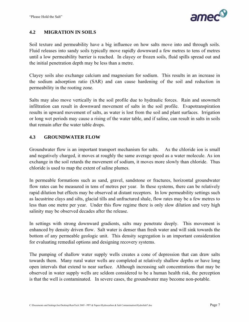
Supply of bottled water, water treatment to remove salts, the drilling of a new well or trucking of water to a cistern are common approaches to lessen landowner concerns. It is not always easy to drill a new well as yield may be lower or deeper groundwater may be less desirable due to higher TDS, iron, sulphate, alkalinity, hardness or sodium concentrations and / or poorer taste. 4.4 OBSERVED ADVERSE EFFECTS The most obvious effects from salt releases are observed in soils. Barren soil with white deposits (Plate 2) at surface, stressed or dead vegetation and crop losses are common observations. Due to rapid dilution, releases to major rivers are seldom large enough to cause adverse effect. However, smaller water bodies and lakes can be severely affected. In low flow settings, dense salt water does not mix well with non saline water in creeks and sloughs and lakes. The salt water will sink to the bottom of the water body and can remain at high concentrations for extended periods. This saline layer would be toxic to most freshwater plant and aquatic organisms. In some small lakes, the presence of a denser saline layer at the bottom can prevent turnover and full mixing of the water body (meromitic). This affects oxygen and nutrient transfer systems. Shallow groundwater systems can rapidly demonstrate salinization over large areas following salt releases. The primary contaminant of concern is chloride due to its higher mobility and higher concentration relative to sodium, potassium, calcium or magnesium. Where the groundwater resides within a low permeability unit, salinization does not pose an immediate risk to existing or potential drinking water supplies. However, salt releases commonly result in chloride and sodium concentrations above criteria in shallow and intermediate depth aquifers.
Plate 2: Surficial Salt Crust
C:\Documents and Settings\Joe\Desktop\RemTech 2005 - PPT & Papers\Hydrocarbon & Salt Contamination\HydroSalt7.doc Page 8
“Please Hold the Salt”
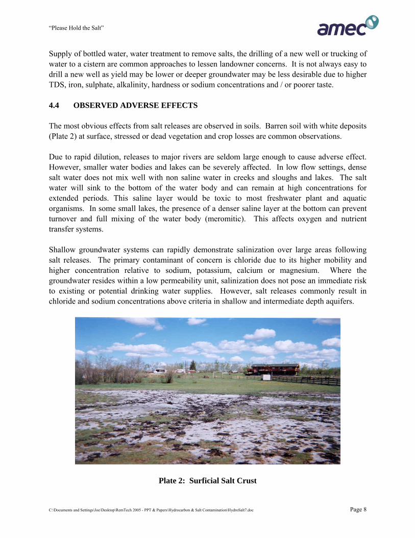
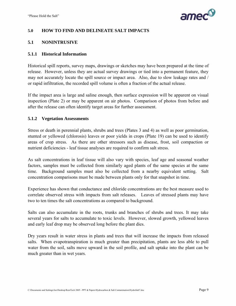
5.0 HOW TO FIND AND DELINEATE SALT IMPACTS 5.1 NONINTRUSIVE 5.1.1 Historical Information Historical spill reports, survey maps, drawings or sketches may have been prepared at the time of release. However, unless they are actual survey drawings or tied into a permanent feature, they may not accurately locate the spill source or impact area. Also, due to slow leakage rates and / or rapid infiltration, the recorded spill volume is often a fraction of the actual release. If the impact area is large and saline enough, then surface expression will be apparent on visual inspection (Plate 2) or may be apparent on air photos. Comparison of photos from before and after the release can often identify target areas for further assessment. 5.1.2 Vegetation Assessments Stress or death in perennial plants, shrubs and trees (Plates 3 and 4) as well as poor germination, stunted or yellowed (chlorosis) leaves or poor yields in crops (Plate 19) can be used to identify areas of crop stress. As there are other stressors such as disease, frost, soil compaction or nutrient deficiencies - leaf tissue analyses are required to confirm salt stress. As salt concentrations in leaf tissue will also vary with species, leaf age and seasonal weather factors, samples must be collected from similarly aged plants of the same species at the same time. Background samples must also be collected from a nearby equivalent setting. Salt concentration comparisons must be made between plants only for that snapshot in time. Experience has shown that conductance and chloride concentrations are the best measure used to correlate observed stress with impacts from salt releases. Leaves of stressed plants may have two to ten times the salt concentrations as compared to background. Salts can also accumulate in the roots, trunks and branches of shrubs and trees. It may take several years for salts to accumulate to toxic levels. However, slowed growth, yellowed leaves and early leaf drop may be observed long before the plant dies. Dry years result in water stress in plants and trees that will increase the impacts from released salts. When evapotranspiration is much greater than precipitation, plants are less able to pull water from the soil, salts move upward in the soil profile, and salt uptake into the plant can be much greater than in wet years.
C:\Documents and Settings\Joe\Desktop\RemTech 2005 - PPT & Papers\Hydrocarbon & Salt Contamination\HydroSalt7.doc Page 9
“Please Hold the Salt”
Plate 3: Dead Stand of Trees in Salt Spill Area
Plate 4: Salt Damaged Leaves
C:\Documents and Settings\Joe\Desktop\RemTech 2005 - PPT & Papers\Hydrocarbon & Salt Contamination\HydroSalt7.doc Page 10
“Please Hold the Salt”
5.1.3 Salt Spill Geophysics Geophysics is the application of the principles of physics to the study of the earth. There are a number of geophysics methods that attempt to measure physical properties of the earth. The physical properties that are most commonly utilized in geophysical investigations are the elasticity, density, magnetic susceptibility, remnant magnetism, electric resistivity or conductivity, radioactivity and thermal conductivity. In order for the selected geophysical method to work, the physical property of the target must contrast with the same physical property of the background material. The contrast must also be large enough to overcome the geological background noise, the instrumental noise and the noise produced by sources of interference. Fortunately for geophysicists, a saltwater spill produces a large change in the electrical resistivity or conductivity of the ground. The reciprocal of electrical resistivity is defined as the electrical conductivity. The addition of salts increases the conductivity or lowers the resistivity of the ground. The units of conductivity are milliSiemens per meter (mS/m) and the units of resistivity are ohm-meters (Ω-m). Most soil and rock minerals are electrical insulators of very high resistivity. In general, the measured conductivity of the ground is electrolytic and takes place through the moisture-filled pores and passages, which are contained, within the insulating matrix. The conductivity is therefore determined for both rocks and minerals by the following:
• porosity: shape and size of pores, number, size and shape of interconnecting passages; • the extent to which pores are filled by water (moisture content); • concentration of dissolved electrolytes in the contained moisture (salts and other ions); • temperature and phase state of the pore water; and • amount and composition of colloids (pre-clays).
Background Conductivity Levels In Western Canada, the background conductivity levels tend to be high in the areas that were covered by the continental glacier. Rocks were finely ground by the glacier, forming various clay minerals. Background conductivity levels are also high in areas where the sulphate levels of the surficial material is elevated or where shale bedrock lies within the depth of investigation. Till or other glacial debris in or near the mountains tend to have very low clay levels. The mountain glaciers did not produce as much clay as the continental glacier and the water produced by the glaciers washed away much of the clay that was formed. Therefore, mountain areas may have low background conductivity levels. Low background values are also observed where thick surficial sand deposits are present.
C:\Documents and Settings\Joe\Desktop\RemTech 2005 - PPT & Papers\Hydrocarbon & Salt Contamination\HydroSalt7.doc Page 11
“Please Hold the Salt”
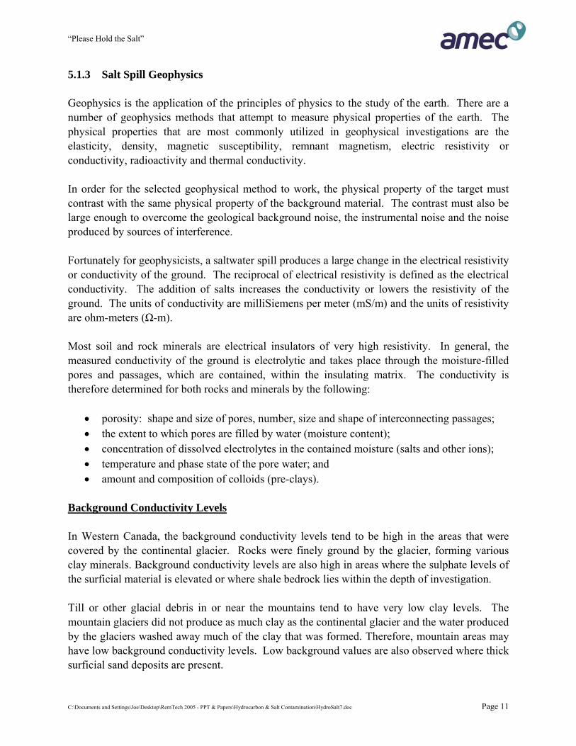
Geophysical Survey Techniques There are many geophysical instruments and techniques that measure the electrical conductivity or resistivity of the ground. A number of these have been designed for mineral exploration. For environmental applications, the preferred instruments are the electromagnetic (EM) ground conductivity meters and resistivity meters. Ground conductivity meters use electromagnetic radiation (the radio portion of the spectrum) and they measure a specific portion (quadrature) of the signal. This measured signal is a complicated function of the transmitter-receiver coil spacing, the operation frequency and the ground conductivity. For surface or near surface salt spills, the EM 38 with shallow measurement depths, and the EM 31 with intermediate measurement depths, are the most commonly used instruments. Plate 5 illustrates the use of an EM 31. Resistivity meters force an electrical current (D-C) through metal electrodes into the ground. Like the EM method, the electrode or coil spacing controls the depth of penetration: the larger the spacing, the deeper the penetration. There are many possible electrode configurations, techniques and interpretation methods. Each of these two geophysics methods have certain advantages and disadvantages.
Plate 5: EM 31 Survey
C:\Documents and Settings\Joe\Desktop\RemTech 2005 - PPT & Papers\Hydrocarbon & Salt Contamination\HydroSalt7.doc Page 12

“Please Hold the Salt”
Advantages of the EM Method 1. The EM method provides a rapid way of determining and mapping the approximate lateral
extent of a salt water spill (Plate 6 and Plate 7). If more than one instrument is used (i.e. EM-31 and EM-38), crude depths can be obtained. For example, saline groundwater plumes can be distinguished from shallow surface impacts.
2. Areas of background conductivity can easily be determined to provide locations for
background soil samples. 3. The source of the salt release can usually be determined as the location of the highest
conductivity. However, if saltwater has flowed over the surface of the ground, there may be areas of ponding where the salt mass and the conductivity would be higher.
4. The relative age of a spill can often be determined. Recent spills have very sharp edges to
the conductive anomalies. Old spills tend to have very diffuse edges. With very old diffuse spills, it becomes difficult to determine where background levels begin.
5. The EM method can be used in industrial areas. Since currents are magnetically induced in
the earth, current injection problems encountered with the resistivity methods are not encountered with the EM method.
Disadvantages of the EM Method 1. If the near surface is very conductive, the radio signal will not penetrate deeply into the
ground. 2. The EM method produces crude depth information. The use of multiple coil spacings or coil
orientations or frequency allows the geophysicist to determine if the salts are shallow, intermediate or deep. Although there are computer inversion programs to determine depths, the values they provide are very poor.
3. Sources of EM interference need to be identified and their effect on the measurements
reduced. Sources of interference can sometimes be identified in the field (e.g. fences, vehicles, etc.) and should be recorded in field notes. EM interference can also be determined from differences in the vertical dipole versus horizontal dipole responses. Changes in the readings when the instruments are rotated horizontally can be used to determine the presence of interference. Often, averaging the maximum and minimum values can reduce or eliminate the effect of interference.
C:\Documents and Settings\Joe\Desktop\RemTech 2005 - PPT & Papers\Hydrocarbon & Salt Contamination\HydroSalt7.doc Page 13
“Please Hold the Salt”
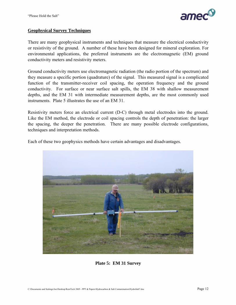
4. The EM method has a limited dynamic range (1-1000 mS/m). At low values of terrain conductivity, it becomes difficult to magnetically induce sufficient current in the ground to produce a detectable magnetic field at the receiver coil. Conversely, at high values of conductivity, the quadrature component of the received magnetic field is not linearly proportional to terrain conductivity.
5. Thin conductive layers will not be observed by the EM method. For example, a saline plume
in a thin shallow sand or gravel aquifer may not be detectable.
Plate 6: EM 31 Anomaly – Deep Impacts
C:\Documents and Settings\Joe\Desktop\RemTech 2005 - PPT & Papers\Hydrocarbon & Salt Contamination\HydroSalt7.doc Page 14
“Please Hold the Salt”
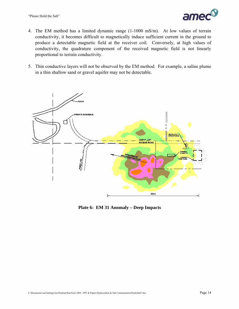
Plate 7: EM 38 Anomaly – Shallow Impacts Advantages of Resistivity Methods 1. Resistivity measurements can provide more reliable information on how the conductivity
changes with depth. Although resistivity profiling (ERT) methods are popular, better depth information is obtained by using a resistivity sounding technique. Recent improvements in computer programs for inversion methods have improved the interpretation of the field data.
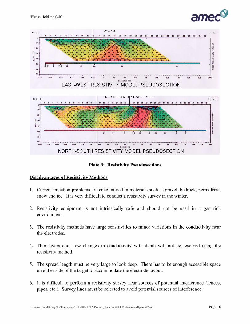
2. The profiling method can produce semi two-dimensional and three-dimensional plots
(Plate 8). 3. Near surface conductive layers enhance rather than restrict the penetration of the electric
current. 4. Recent improvements in equipment have improved the productivity of the method.
C:\Documents and Settings\Joe\Desktop\RemTech 2005 - PPT & Papers\Hydrocarbon & Salt Contamination\HydroSalt7.doc Page 15
“Please Hold the Salt”
Plate 8: Resistivity Pseudosections Disadvantages of Resistivity Methods 1. Current injection problems are encountered in materials such as gravel, bedrock, permafrost,
snow and ice. It is very difficult to conduct a resistivity survey in the winter. 2. Resistivity equipment is not intrinsically safe and should not be used in a gas rich
environment.
3. The resistivity methods have large sensitivities to minor variations in the conductivity near the electrodes.
4. Thin layers and slow changes in conductivity with depth will not be resolved using the
resistivity method. 5. The spread length must be very large to look deep. There has to be enough accessible space
on either side of the target to accommodate the electrode layout. 6. It is difficult to perform a resistivity survey near sources of potential interference (fences,
pipes, etc.). Survey lines must be selected to avoid potential sources of interference.
C:\Documents and Settings\Joe\Desktop\RemTech 2005 - PPT & Papers\Hydrocarbon & Salt Contamination\HydroSalt7.doc Page 16
“Please Hold the Salt”
5.2 INTRUSIVE 5.2.1 Soil Sampling When an EM survey has identified an anomaly, then sufficient samples should be collected within the anomaly to correlate apparent conductance with soil salinity values. This approach greatly reduces the number of soil samples and analyses required to delineate the impact area. Where salts are confined to the unsaturated zone above the water table, soil sampling alone may be sufficient to delineate the horizontal and vertical limits of impact. Sampling methods may include some or all of hand tools, auger drilling or coring. Sampling and analytical intervals should be at least every 0.5 m near surface and every 1.0 m at depths below 2.0 m. Discrete samples should also be collected from any major changes in soil type or geologic deposit. Where surficial deposits are coarse, the depth of investigation should extend to a low permeability barrier. If sodium chloride is the only known contaminant, then screening analyses can be limited to conductance and soluble chloride (by saturated paste). Ten to twenty percent of the samples can later be selected for detailed salinity analyses that includes pH, major ions and calculated SAR. 5.2.2 Hydrogeologic Investigations Salt spills that penetrate deeply into the soil profile have the potential to affect groundwater. Additionally, salts that were initially found at shallow depths may be carried downward to the water table. Once into the groundwater system, lateral and vertical flow can carry salt long distances. In highly permeable sands and gravels or fractured bedrock, flow rates can be tens of metres / year (or more). In lower permeable deposits, flow rates are measured in metres / year. In very low flow settings, such as tight clays with little horizontal gradient, migration may be less than a metre / year. It is important to note that where salt concentrations were high at the time of release, that due to diffusion, significant chloride concentrations will be found much further from the source then the distance predicted by the mean flow rate of groundwater. Hydrogeologic investigations should include water table monitor wells and in many geologic settings should also include deeper piezometers. In simple settings, a minimum of three water table installations is required to determine horizontal groundwater flow. In complex settings, additional effort will be required to fully evaluate groundwater flow patterns. In surficial sand aquifers, stratification due to density differences between fresh groundwater and saline water may occur. Thus sampling from both the top and bottom of the aquifer may be required to properly characterize groundwater quality. Two to three orders of magnitude higher chloride concentrations are commonly observed at the base of the aquifer than those observed at the water table surface.
C:\Documents and Settings\Joe\Desktop\RemTech 2005 - PPT & Papers\Hydrocarbon & Salt Contamination\HydroSalt7.doc Page 17
“Please Hold the Salt”
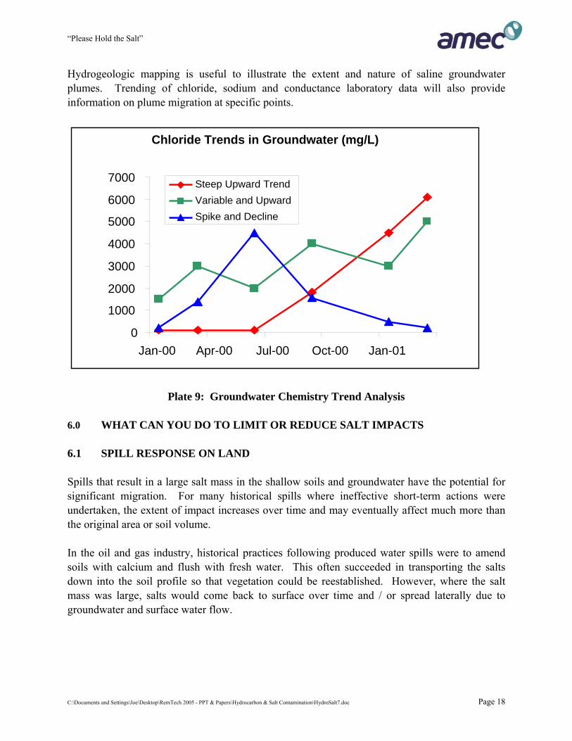
Hydrogeologic mapping is useful to illustrate the extent and nature of saline groundwater plumes. Trending of chloride, sodium and conductance laboratory data will also provide information on plume migration at specific points.
Chloride Trends in Groundwater (mg/L)
0
1000
2000
3000
4000
5000
6000
7000
Jan-00 Apr-00 Jul-00 Oct-00 Jan-01
Steep Upward TrendVariable and UpwardSpike and Decline
Plate 9: Groundwater Chemistry Trend Analysis 6.0 WHAT CAN YOU DO TO LIMIT OR REDUCE SALT IMPACTS 6.1 SPILL RESPONSE ON LAND Spills that result in a large salt mass in the shallow soils and groundwater have the potential for significant migration. For many historical spills where ineffective short-term actions were undertaken, the extent of impact increases over time and may eventually affect much more than the original area or soil volume. In the oil and gas industry, historical practices following produced water spills were to amend soils with calcium and flush with fresh water. This often succeeded in transporting the salts down into the soil profile so that vegetation could be reestablished. However, where the salt mass was large, salts would come back to surface over time and / or spread laterally due to groundwater and surface water flow.
C:\Documents and Settings\Joe\Desktop\RemTech 2005 - PPT & Papers\Hydrocarbon & Salt Contamination\HydroSalt7.doc Page 18
“Please Hold the Salt”
•
•
•
•
•
Actions taken at the time of the spill and in the days or weeks that follow give excellent value for the money expended. Key actions should include:
containing and recovering any free liquids to reduce the area and depth of potential impact;
by ditching or berming, divert the potential for surface water run-on from entering the spill area;
if the shallow soils are heavily salinized, then covering the spill area with sand bagged tarps will reduce the potential for spread due to rainfall or snow melt while remediation decisions are made;
assess the site to determine the lateral and vertical extent of impacts; and
undertake actions at the source that will remove or minimize the potential for salt migration.
One caution regarding subsurface salt water releases from pipelines that fail due to corrosion. Experience has proven that fluid volume releases may be 10 to more than 100 times higher then can be estimated by visual observations at the time the release is observed at surface. Pinhole corrosion or mechanical rub failures may leak for months before the release rate is high enough for surface expression (that someone notices) or production volume decreases enough that an investigation is triggered. The riskiest settings are where shallow geologic deposits have high permeability – such as sand, gravel and fractured bedrock. 6.2 PROTECTION OF SURFACE WATER Small releases to surface waters are usually diluted quickly and have little potential for harm. However, rapid response is required if a large volume highly saline fluid is released to a surface water body. Short term damming of small watercourses and pumping / disposal of captured fluids may be necessary. In sloughs or small lakes, the saline fluid may sink to the bottom and testing at the time of assessment must include basal samples. Removing all water from small water bodies may be necessary and in some critical habitat areas, fresh replacement water may be necessary. If a spill has affected a permanent water body, then approval of a remediation plan will be required from Provincial and Federal agencies. If a significant adverse affect has occurred or fish have been killed, then charges are likely.
C:\Documents and Settings\Joe\Desktop\RemTech 2005 - PPT & Papers\Hydrocarbon & Salt Contamination\HydroSalt7.doc Page 19
“Please Hold the Salt”
6.3 DIG AND DUMP Where the source area is highly saline and accessible, the least expensive remediation may be the excavation and disposal to landfill. If this option is considered to be economically feasible, then the excavation should occur as quickly after the release as possible. Even a one or two year delay can result in significant migration and much larger soil volumes. If the soil contains more than 3,000 mg/kg chloride, the soil must be sent to a landfill with a synthetic liner and leachate collection system. Otherwise the saline soil would have the potential to adversely affect groundwater below the landfill. Field guidance of saline soil excavations is considerably more difficult than hydrocarbons. There is little or no staining and no vapours to measure. Soil pastes can be made in the field for conductivity and / or chloride measurements that can provide general guidance. However, as the field method varies substantially from the lab saturated paste extract, the correlation between field and lab can vary significantly. 6.4 SOIL AMENDMENTS In coarse grained settings with low clay contents in shallow soils, minimal amendments are likely necessary. For sodium chloride affected clayey soils, calcium amendments are required to lower the SAR and protect soil structure. For new spills, where efforts are planned to reduce salinity within the upper soils, amendments should be applied early in the remedial program while conductivity is still high. However, if sodium and chloride ions are not removed from the growing zone by recovery or dilution, then calcium amendments will provide little benefit. The two most common amendments are calcium sulphate (gypsum) and calcium nitrate. Gypsum has low solubility and is a good long-term amendment. Calcium nitrate is highly soluble and is a good short term fast acting amendment. Although, the nitrate component may be a desired fertilizer, if the application rate is too high, this compound has the potential to affect surface water and groundwater. Thus there are some sensitive settings where calcium nitrate should be used sparingly or not at all. Old spill sites where clayey soils have hardened due to high SAR, deep ripping and organic amendments may be required to improve soil structure. Significant soil structure improvements may take several applications and many years of efforts.
C:\Documents and Settings\Joe\Desktop\RemTech 2005 - PPT & Papers\Hydrocarbon & Salt Contamination\HydroSalt7.doc Page 20
“Please Hold the Salt”
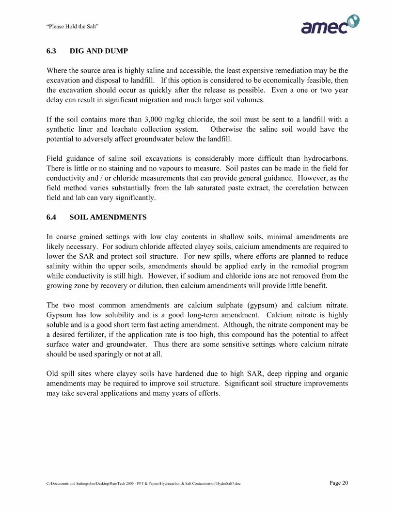
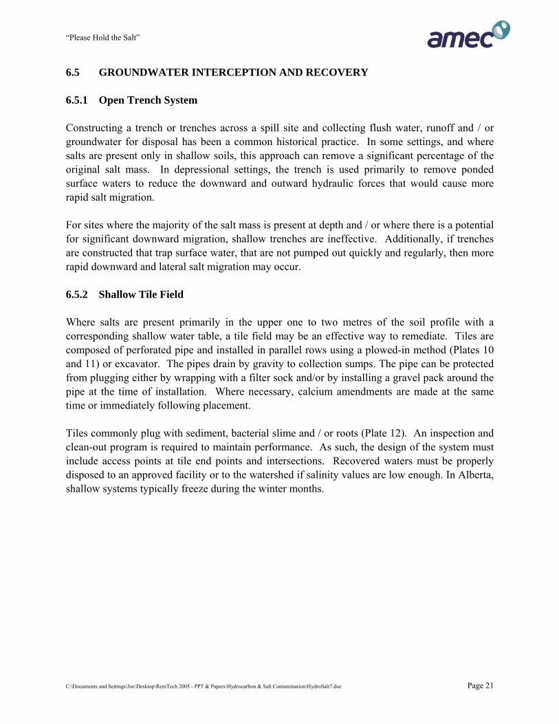
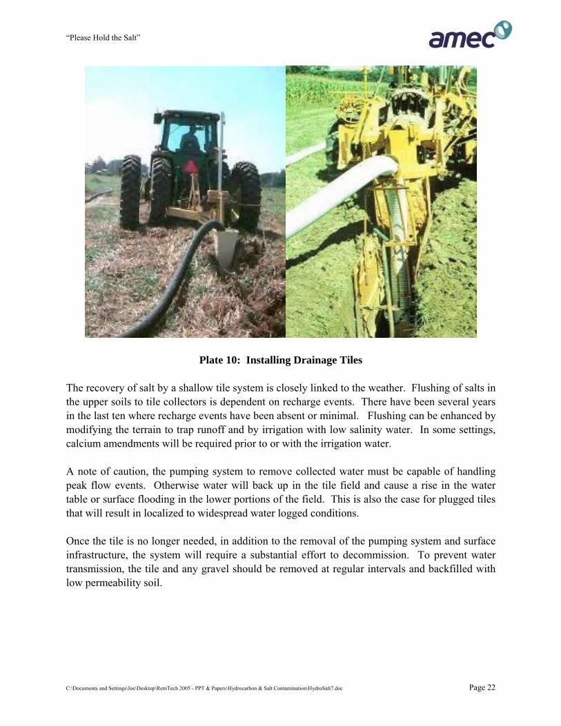
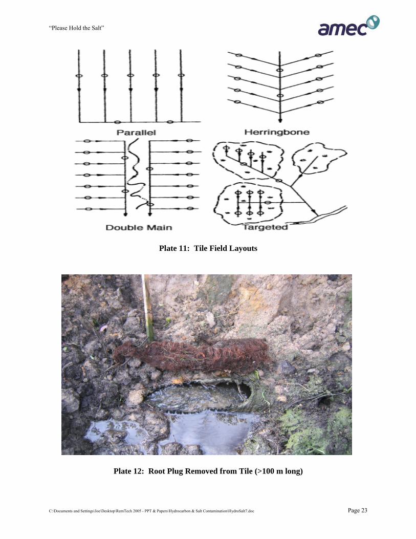
6.5 GROUNDWATER INTERCEPTION AND RECOVERY 6.5.1 Open Trench System Constructing a trench or trenches across a spill site and collecting flush water, runoff and / or groundwater for disposal has been a common historical practice. In some settings, and where salts are present only in shallow soils, this approach can remove a significant percentage of the original salt mass. In depressional settings, the trench is used primarily to remove ponded surface waters to reduce the downward and outward hydraulic forces that would cause more rapid salt migration. For sites where the majority of the salt mass is present at depth and / or where there is a potential for significant downward migration, shallow trenches are ineffective. Additionally, if trenches are constructed that trap surface water, that are not pumped out quickly and regularly, then more rapid downward and lateral salt migration may occur. 6.5.2 Shallow Tile Field Where salts are present primarily in the upper one to two metres of the soil profile with a corresponding shallow water table, a tile field may be an effective way to remediate. Tiles are composed of perforated pipe and installed in parallel rows using a plowed-in method (Plates 10 and 11) or excavator. The pipes drain by gravity to collection sumps. The pipe can be protected from plugging either by wrapping with a filter sock and/or by installing a gravel pack around the pipe at the time of installation. Where necessary, calcium amendments are made at the same time or immediately following placement. Tiles commonly plug with sediment, bacterial slime and / or roots (Plate 12). An inspection and clean-out program is required to maintain performance. As such, the design of the system must include access points at tile end points and intersections. Recovered waters must be properly disposed to an approved facility or to the watershed if salinity values are low enough. In Alberta, shallow systems typically freeze during the winter months.
C:\Documents and Settings\Joe\Desktop\RemTech 2005 - PPT & Papers\Hydrocarbon & Salt Contamination\HydroSalt7.doc Page 21
“Please Hold the Salt”
Plate 10: Installing Drainage Tiles The recovery of salt by a shallow tile system is closely linked to the weather. Flushing of salts in the upper soils to tile collectors is dependent on recharge events. There have been several years in the last ten where recharge events have been absent or minimal. Flushing can be enhanced by modifying the terrain to trap runoff and by irrigation with low salinity water. In some settings, calcium amendments will be required prior to or with the irrigation water. A note of caution, the pumping system to remove collected water must be capable of handling peak flow events. Otherwise water will back up in the tile field and cause a rise in the water table or surface flooding in the lower portions of the field. This is also the case for plugged tiles that will result in localized to widespread water logged conditions. Once the tile is no longer needed, in addition to the removal of the pumping system and surface infrastructure, the system will require a substantial effort to decommission. To prevent water transmission, the tile and any gravel should be removed at regular intervals and backfilled with low permeability soil.
C:\Documents and Settings\Joe\Desktop\RemTech 2005 - PPT & Papers\Hydrocarbon & Salt Contamination\HydroSalt7.doc Page 22
“Please Hold the Salt”
Plate 11: Tile Field Layouts
Plate 12: Root Plug Removed from Tile (>100 m long)
C:\Documents and Settings\Joe\Desktop\RemTech 2005 - PPT & Papers\Hydrocarbon & Salt Contamination\HydroSalt7.doc Page 23
“Please Hold the Salt”
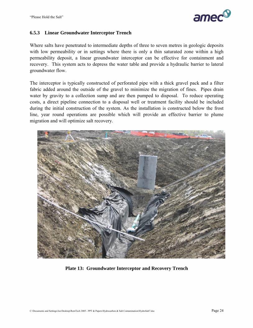
6.5.3 Linear Groundwater Interceptor Trench Where salts have penetrated to intermediate depths of three to seven metres in geologic deposits with low permeability or in settings where there is only a thin saturated zone within a high permeability deposit, a linear groundwater interceptor can be effective for containment and recovery. This system acts to depress the water table and provide a hydraulic barrier to lateral groundwater flow. The interceptor is typically constructed of perforated pipe with a thick gravel pack and a filter fabric added around the outside of the gravel to minimize the migration of fines. Pipes drain water by gravity to a collection sump and are then pumped to disposal. To reduce operating costs, a direct pipeline connection to a disposal well or treatment facility should be included during the initial construction of the system. As the installation is constructed below the frost line, year round operations are possible which will provide an effective barrier to plume migration and will optimize salt recovery.
Plate 13: Groundwater Interceptor and Recovery Trench
C:\Documents and Settings\Joe\Desktop\RemTech 2005 - PPT & Papers\Hydrocarbon & Salt Contamination\HydroSalt7.doc Page 24
“Please Hold the Salt”
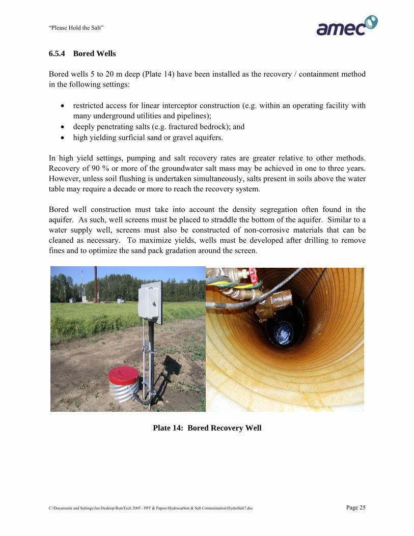
6.5.4 Bored Wells Bored wells 5 to 20 m deep (Plate 14) have been installed as the recovery / containment method in the following settings:
• restricted access for linear interceptor construction (e.g. within an operating facility with many underground utilities and pipelines);
• deeply penetrating salts (e.g. fractured bedrock); and • high yielding surficial sand or gravel aquifers.
In high yield settings, pumping and salt recovery rates are greater relative to other methods. Recovery of 90 % or more of the groundwater salt mass may be achieved in one to three years. However, unless soil flushing is undertaken simultaneously, salts present in soils above the water table may require a decade or more to reach the recovery system. Bored well construction must take into account the density segregation often found in the aquifer. As such, well screens must be placed to straddle the bottom of the aquifer. Similar to a water supply well, screens must also be constructed of non-corrosive materials that can be cleaned as necessary. To maximize yields, wells must be developed after drilling to remove fines and to optimize the sand pack gradation around the screen.
Plate 14: Bored Recovery Well
C:\Documents and Settings\Joe\Desktop\RemTech 2005 - PPT & Papers\Hydrocarbon & Salt Contamination\HydroSalt7.doc Page 25
“Please Hold the Salt”
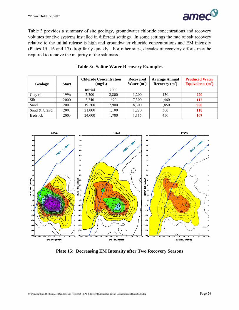
Table 3 provides a summary of site geology, groundwater chloride concentrations and recovery volumes for five systems installed in different settings. In some settings the rate of salt recovery relative to the initial release is high and groundwater chloride concentrations and EM intensity (Plates 15, 16 and 17) drop fairly quickly. For other sites, decades of recovery efforts may be required to remove the majority of the salt mass.
Table 3: Saline Water Recovery Examples
Chloride Concentration (mg/L)
Recovered Water (m3)
Average Annual Recovery (m3)
Produced Water Equivalents (m3) Geology Start
Initial 2005 Clay till 1996 2,300 2,800 1,200 130 270 Silt 2000 2,240 690 7,300 1,460 112 Sand 2001 19,200 2,900 8,300 1,850 920 Sand & Gravel 2001 21,000 1,100 1,220 300 118 Bedrock 2003 24,000 1,700 1,115 450 107
Plate 15: Decreasing EM Intensity after Two Recovery Seasons
C:\Documents and Settings\Joe\Desktop\RemTech 2005 - PPT & Papers\Hydrocarbon & Salt Contamination\HydroSalt7.doc Page 26
“Please Hold the Salt”
C:\Documents and Settings\Joe\Desktop\RemTech 2005 - PPT & Papers\Hydrocarbon & Salt Contamination\HydroSalt7.doc Page 27
0.0
2.0
4.0
6.0
8.0
10.0
12.0
14.0
16.0
Aug-03 Dec-03 Apr-04 Aug-04 Dec-04 Apr-05 Aug-05 Dec-05
Volu
me
(m3/
day)
0
10000
20000
30000
40000
50000
60000
70000
Chl
orid
e (m
g/L)
Daily Volume Chloride
Total Recovery = 2000 m3
Produced H20 = 400 m3
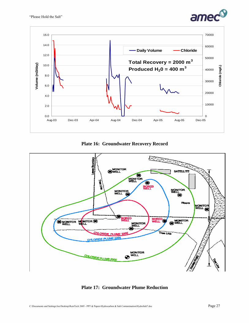
Plate 16: Groundwater Recovery Record
Plate 17: Groundwater Plume Reduction

“Please Hold the Salt”
6.5.5 Keeping Things Running To maximize containment and recovery, recovery systems should be winterized and operated year round. As the salinity of the water will decrease over time, the system design should be based on fresh water principles that include pipeline insulation or burial below the local frost line. Polyethylene piping is preferred as it can withstand freezing without bursting (unlike steel, fiberglass or PVC). Operating budgets should include money for inspection, recovery volume measurements, replacement parts and well servicing. Extended down time is undesirable as the salt plume may migrate past the most effective zone of influence of the recovery system. Groundwater systems will require periodic maintenance that will vary with the site specific setting, chemical characteristics of the recovered water and bacteriological profile. Well servicing to remove sediment from the casing below the pump, redevelop the well, remove scale (Plate 18) by jetting or acidification, or shock chlorination to treat biofouling are common requirements. Most recovery systems require an Approval under the Water Act. Monitoring requirements under the Approval vary from site to site, but all include volume measurements and analytical requirements. Reporting is either required annually or at the request of the director. In either event, it is important to evaluate the effectiveness of the recovery system and monitoring program at least yearly.
Plate 18: Calcium, Iron Oxide and Magnetite Crystal Scale on Groundwater Pump
C:\Documents and Settings\Joe\Desktop\RemTech 2005 - PPT & Papers\Hydrocarbon & Salt Contamination\HydroSalt7.doc Page 28
“Please Hold the Salt”
6.6 OTHER REMEDIATION METHODS Phytoremediation uses plants that accumulate salts in their above ground tissues that can be harvested and removed. The method is useful where salts are shallow and long timeframes are available for remediation. Soils can be washed to reduce salt content. This involves excavation and placement into a leaching pile or running soil through soil washing equipment. Clean sands and gravels can often be washed cost effectively. Fine grained clayey soils are difficult to wash and the soil structure is altered undesirably. Natural attenuation for salts is primarily based on dilution through dispersion and possible salt losses from the local system through surface water flow or groundwater discharge to a river or stream. This method may be acceptable for relatively minor salt impacts where adverse effects are absent or minimal. For large and intensely saline salt affected areas, this is not an effective approach and will result in an expanding impact area. Research into other remediation methods is ongoing. 7.0 CLOSURE ISSUES FOR SALTS TODAY AND IN THE FUTURE 7.1 INDUSTRY Managers and decision-makers of operating industries have overlapping priorities that affect how spills are managed. Most facility managers are asked to steward to four main principles: safety of the workers and public; quality of the product they produce; minimizing the costs of production; and maintaining a profitable schedule. Profits are typically measured over short time periods of months, quarters or years. Managers are typically evaluated and rewarded for performance over these short time intervals. Once the primary spill response is completed, residual contaminants may represent a long-term liability. This cost may not be well understood due to limited assessment information. The end of life cycle liability should be determined and included in the day to day balance sheet of the facility. This would provide impetus to undertake measures to:
• reduce the likelihood of future spills; • determine the nature and extent of the liability; and • to manage and contain the liability during the operating period of the facility.
C:\Documents and Settings\Joe\Desktop\RemTech 2005 - PPT & Papers\Hydrocarbon & Salt Contamination\HydroSalt7.doc Page 29
“Please Hold the Salt”
7.2 LANDOWNERS For most privately owned land, spills are of great concern to the landowner – particularly if there are visible impacts or crop loss. If it is leased land, then the expectation is that it be returned to predisturbance conditions. The Province also expects equivalent capability be restored. The level of concern or interest expressed by landowners is extremely varied. Some seem to care little or not at all. Others are demanding but reasonable. A few are at the other extreme that includes abusive or threatening behaviours. An often successful strategy by the landowner to gain attention is to involve regulators, media and non-governmental organizations to increase the profile and importance of their concern. It is important for industry to take a consistent but responsive approach to landowner issues regardless of their behaviour. For small spills or ones with low salinity, the focus should be to quickly remediate the site. Large or complex highly saline sites require a management plan to contain impacts, recover salts and compensate landowners. 7.3 OBTAINING SITE CLOSURE For specified land in Alberta such as oil and gas leases, the leaseholder can obtain a Reclamation Certificate. This process has been recently revised and is beyond the scope of this paper. However, there is an obligation to thoroughly assess each lease for physical and chemical changes that may have occurred during operations. Based on the criteria that apply to that setting and in comparison to pre-disturbance or background conditions, the site must be remediated and reclaimed. Industrial sites that operate with an Approval under the Environmental Protection and Enhancement Act, have a requirement to complete soil and groundwater monitoring on an ongoing basis. Actions to limit and remediate releases are expected to occur during the operating period. At the end of life cycle, a decommissioning plan must be filed with Alberta Environment that provides a summary of actions and timelines to reach closure. Spills with large environmental importance (such as the large oil release in the summer of 2005 in Lake Wabumun), or ones not dealt with effectively by the operator will result in an Environmental Protection Order. The Order will specify required actions, set out timelines and will require frequent reporting.
C:\Documents and Settings\Joe\Desktop\RemTech 2005 - PPT & Papers\Hydrocarbon & Salt Contamination\HydroSalt7.doc Page 30
“Please Hold the Salt”
7.4 RISK ASSESSMENT & SITE MANAGEMENT If salts in soil and groundwater exceed background and have the potential to limit land use, then regulatory closure may not be possible on private lands if a sensitive use is contemplated (e.g. strawberries or a fish pond). There may be more flexibility on Crown land, where future land use is typically forest. It is possible that the Crown may agree that the right mix of grasses at closure may be acceptable in that it provides improved ungulate habitat. Risk assessment is useful to identify pathways and receptors. If salts are to remain, then the fate and transport of the salt over time must be predicted. Protection of groundwater and surface water resources must be demonstrated. Additionally, no significant expansion of the area of saline soils is likely to be acceptable to landowners or regulators. If the landowner is agreeable to risk assessment, then a site management plan will be necessary. Alberta Environment should also be asked to comment on the plan. A site management plan would typically contain some or all of the following elements:
• if a recovery system is in place, then this would continue to be operated and maintained; • soil amendments may be added periodically as necessary to reduce SAR; • land use in the saline area would be restricted to growing salt tolerant plants and shallow
water wells or ponds would not be permitted; • any excavations in the saline area would require soils to remain within the management
area or be sent for disposal; • a groundwater monitoring plan would continue; and • reporting would take place annually at first and periodically afterwards to document the
success of the plan and to provide a mechanism for adjusting management tools and actions.
C:\Documents and Settings\Joe\Desktop\RemTech 2005 - PPT & Papers\Hydrocarbon & Salt Contamination\HydroSalt7.doc Page 31
“Please Hold the Salt”
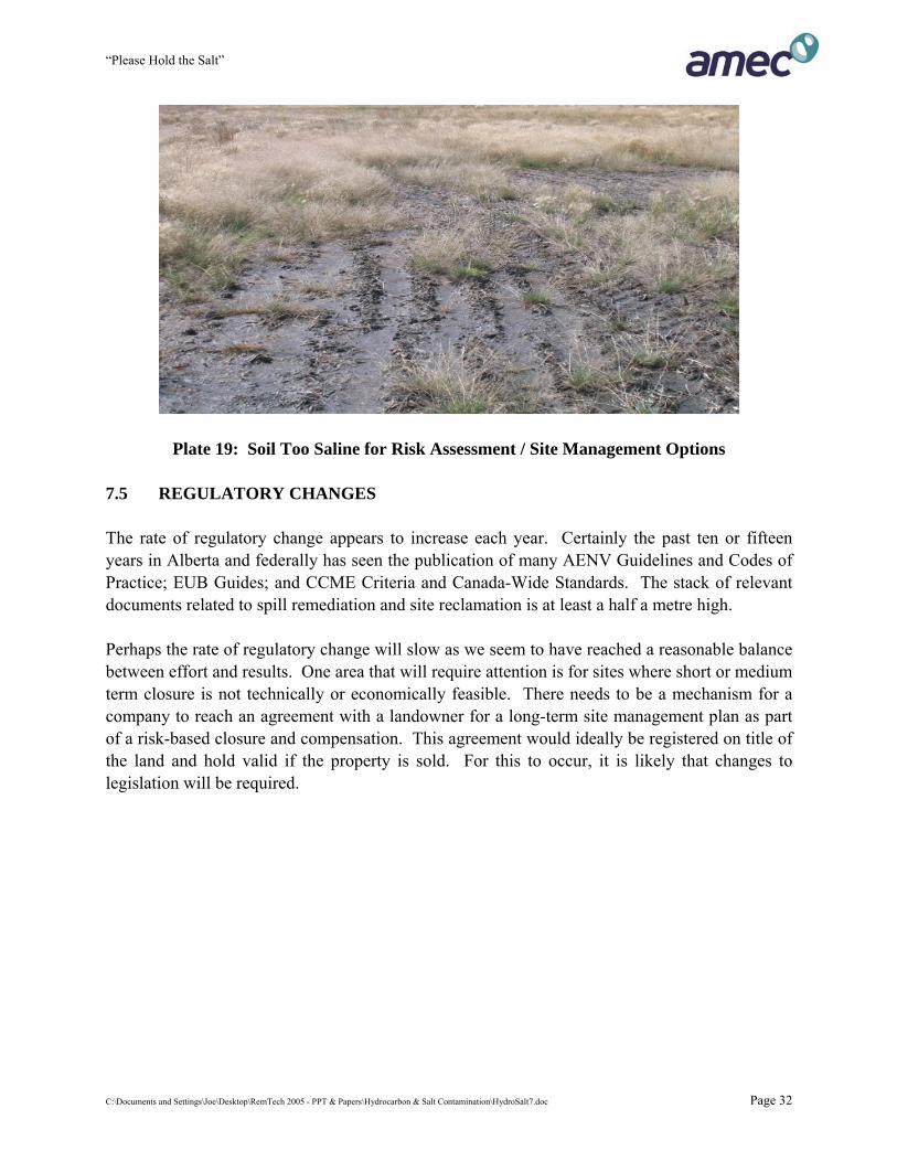
Plate 19: Soil Too Saline for Risk Assessment / Site Management Options 7.5 REGULATORY CHANGES The rate of regulatory change appears to increase each year. Certainly the past ten or fifteen years in Alberta and federally has seen the publication of many AENV Guidelines and Codes of Practice; EUB Guides; and CCME Criteria and Canada-Wide Standards. The stack of relevant documents related to spill remediation and site reclamation is at least a half a metre high. Perhaps the rate of regulatory change will slow as we seem to have reached a reasonable balance between effort and results. One area that will require attention is for sites where short or medium term closure is not technically or economically feasible. There needs to be a mechanism for a company to reach an agreement with a landowner for a long-term site management plan as part of a risk-based closure and compensation. This agreement would ideally be registered on title of the land and hold valid if the property is sold. For this to occur, it is likely that changes to legislation will be required.
C:\Documents and Settings\Joe\Desktop\RemTech 2005 - PPT & Papers\Hydrocarbon & Salt Contamination\HydroSalt7.doc Page 32