platinum metals · pdf fileing, medicine and science (1). the opportunities that are opened up...
TRANSCRIPT
Platinum
Metals
Review
www.platinummetalsreview.comE-ISSN 1471–0676
VOLUME 54 NUMBER 4 OCTOBER 2010

© Copyright 2010 Johnson Matthey PLC
http://www.platinummetalsreview.com/
Platinum Metals Review is published by Johnson Matthey PLC, refiner and fabricator of the precious metals and sole marketing agent for the sixplatinum group metals produced by Anglo Platinum Limited, South Africa.
All rights are reserved. Material from this publication may be reproduced for personal use only but may not be offered for re-sale or incorporatedinto, reproduced on, or stored in any website, electronic retrieval system, or in any other publication, whether in hard copy or electronic form,without the prior written permission of Johnson Matthey. Any such copy shall retain all copyrights and other proprietary notices, and any disclaimercontained thereon, and must acknowledge Platinum Metals Review and Johnson Matthey as the source.
No warranties, representations or undertakings of any kind are made in relation to any of the content of this publication including the accuracy,quality or fitness for any purpose by any person or organisation.
203 © 2010 Johnson Matthey
•Platinum Metals Rev., 2010, 54, (4), 203•
Editorial Team: Jonathan Butler (Publications Manager); Sara Coles (Assistant Editor); Margery Ryan (Editorial Assistant); Keith White (Senior Information Scientist)
Platinum Metals Review, Johnson Matthey PLC, Orchard Road, Royston, Hertfordshire SG8 5HE, UKE-mail: [email protected]
E-ISSN 1471–0676
Platinum Metals ReviewA quarterly journal of research on the platinum group metals
and of developments in their application in industryhttp: //www.platinummetalsreview.com/
OCTOBER 2010 VOL. 54 NO. 4
Contents
50th Anniversary of the Laser 220044
An editorial by Sara Coles
The Platinum Group Element Deposits of the Bushveld Complex 220055
in South Africa
By R. Grant Cawthorn
SAE 2010 World Congress 221166
A conference review by Timothy V. Johnson
Effect of Particle Size of Platinum and Platinum-Cobalt Catalysts 222233
on Stability Against Load Cycling
By Koichi Matsutani, Katsuichiro Hayakawaand Tomoyuki Tada
“Handbook of Green Chemistry – Green Catalysis” 223333
A book review by Kingsley Cavell,Stan Golunski and David Miller
The 24th Santa Fe Symposium on Jewelry 223399
Manufacturing Technology
A conference review by Christopher W. Corti
PGM Highlights: Platinum in Next-Generation Materials 224444
for Data Storage
By Marge Ryan
Michele Peyrone (1813–1883), Discoverer of Cisplatin 225500
By George B. Kauffman, Raffaele Pentimalli,Sandro Doldi and Matthew D. Hall
“Dental Materials at a Glance” 225577
A book review by Dan Carter
Abstracts 226600
Patents 226633
Final Analysis: Melting the PGMs: 226666
The State of the Art in Welding Platinum
By John C. Wright
The year 2010 marks the 50th anniversary of the
first discovery of the laser (1). Today, solid state
lasers dominate the laser market and one of the
most widely used types is the yttrium aluminium
garnet (YAG) laser. Platinum group metals (pgms)
play a vital role in the production of these lasers –
monocrystalline YAG is grown in iridium crucibles,
whose chemical compatibility with molten oxides
in slightly oxidising conditions allows single crys-
tals to be grown with the optical and chemical puri-
ty required for laser applications (2, 3).
A look through the Platinum Metals Review
archive reveals that this is not the end of the story
for pgms and lasers.YAG lasers are used for welding
jewellery alloys (4) and as John Wright points out
in this issue of Platinum Metals Review, the best
equipped jewellery manufacturers may have both
laser and pulse argon arc welders in their work-
shops (5). Laser welding is a relatively new tech-
nique, and jewellers can design appropriately to
take advantage of its unique attributes. Platinum’s
low thermal diffusivity means that there is a very
narrow heat-affected zone, thus it is possible to pre-
serve work hardening at the end of the manufactur-
ing process or for jewellery repair, and laser welds
can be made close to gemstones and delicate
components without damaging them (6). Iridium
itself can be welded by laser for uses as diverse as
spark plug electrodes, nuclear fuel containers and,
appropriately, crucibles for crystal growth (7).
Manufacturing processes can also benefit from
laser technology. Ceramic substrates used to make
glass manufacturing equipment can be coated
with a platinum-rhodium alloy, and are laser drilled
prior to coating to ensure a strong, uniform adhe-
sion of the coating (8).
Lasers can play a role in developing or improving
pgm materials for a variety of applications. The
laser flash method uses a ruby laser to measure
thermal conductivity of pgms and their alloys, as a
way to determine their suitability for ultra high-
temperature structural applications among others
(9, 10). Laser-based techniques can even be used to
study the behaviour of pgms in naturally occurring
mineral deposits (11).
Lasers are a symbol of modern life and pervade
all aspects of today’s society, from the familiar CDs
and DVDs to broader applications in manufactur-
ing, medicine and science (1). The opportunities
that are opened up in diverse applications of the
pgms – and even in the study of pgm ores – mean
that lasers and pgms should have a long future
together.
SARA COLES, Assistant Editor
References
1 T. W. Hänsch, Laser Photon. Rev., 2010, 44, (1), A5
2 B. Cockayne, Platinum Metals Rev., 1968, 1122, (1), 16
3 B. Cockayne, Platinum Metals Rev., 1974, 1188, (3), 86
4 J. C. Wright, Platinum Metals Rev, 2002, 4466, (2), 66
5 J. C. Wright, Platinum Metals Rev., 2010, 5544, (4), 266
6 D. Miller, K. Vuso, P. Park-Ross and C. Lang, Platinum
Metals Rev., 2007, 5511, (1), 23
7 E. K. Ohriner, Platinum Metals Rev., 2008, 5522, (3), 186
8 C. Couderc, Platinum Metals Rev., 2010, 5544, (3), 186
9 Y. Terada, K. Ohkubo and T. Mohri, Platinum Metals
Rev., 2005, 4499, (1), 21
10 Y. Terada, Platinum Metals Rev., 2008, 5522, (4), 208
11 D. A. Holwell and I. McDonald, Platinum Metals Rev.,
2010, 5544,, (1), 26
204 © 2010 Johnson Matthey
doi:10.1595/147106710X526046 •Platinum Metals Rev., 2010, 54, (4), 204•
Editorial
50th Anniversary of the Laser

By R. Grant Cawthorn
School of Geosciences, University of the Witwatersrand,Private Bag 3, Johannesburg 2050, South Africa;
E-mmail: [email protected]
There are enough platinum group element deposits in
the Bushveld Complex in South Africa to supply world
demands for many decades or even a century using
current mining techniques. Demonstrated reserves and
resources published by mining companies make
detailed calculations up to a maximum of about twenty
years ahead, but there is abundant and adequate
geological evidence that these deposits continue far
beyond where mining companies have proven accord-
ing to rigorous international reporting codes. For each
1 km of depth into the Earth in the Bushveld Complex
there is in the order of 350 million oz of platinum. For
comparison, annual production of platinum from the
Bushveld Complex currently is only around 5 million
oz. The distinction between ‘reserves’,‘resources’ and
‘deposits’ is also explained in this article.
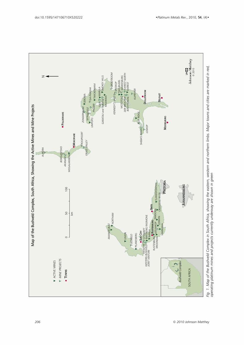
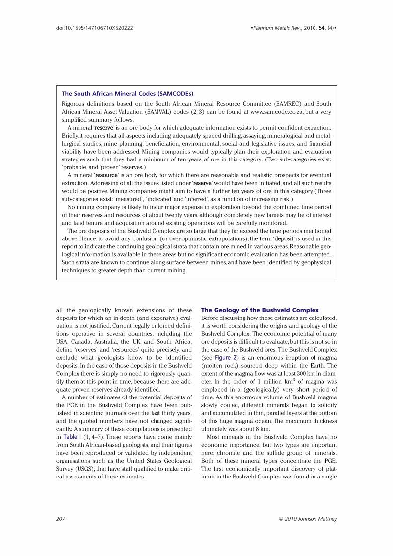
IntroductionIn the minerals sector of world economics, the
Bushveld Complex in South Africa (Figure 1) is
renowned for its overwhelming deposits of platinum
group elements (PGE) and chromium (over 80% of
the world’s deposits of each according to Crowson
(1)). Inevitably, from time to time, the question is
raised as to how reliable those estimates are. The
occurrences of all other mineral deposits are scat-
tered around the world in an erratic way. Each deposit
type has well-understood geological processes that
operated to form them, but those processes have
operated usually all over the world and in many cases
throughout long periods of Earth’s 4.6 billion-year his-
tory, so that most commodities are mined in many
different countries. Therefore, the PGEs, and espe-
cially platinum itself, are unusual in that they are
largely concentrated in a single location.
Mining companies may only publish ‘reserves’ and
‘resources’ of platinum. However, as discussed below
(see box) (2, 3), this figure represents only what has
been rigorously quantified in the short- to medium-
term mining plans of these companies, and excludes
205 © 2010 Johnson Matthey
•Platinum Metals Rev., 2010, 54, (4), 205–215•
The Platinum Group Element Depositsof the Bushveld Complex in South Africa
doi:10.1595/147106710X520222 http://www.platinummetalsreview.com/
206 © 2010 Johnson Matthey
doi:10.1595/147106710X520222 •Platinum Metals Rev., 2010, 54, (4)•
SSUU
NNCC
IITTYY
RRUU
SSTT
EENN
BBUU
RRGG
LEEU
WKO
P
BBRR
IITTSS
PPRR
EETT
OORR
IIAA
JJ OOHH
AANN
NNEE
SSBB
UURR
GG
DDUU
LLLL
SSTT
RROO
OOMM
PPOO
LLOO
KKWW
AANN
EE
MMOO
KKOO
PPAA
NNEE
NO
RTH
AM
AM
AN
DEL
BULT
UN
ION
SED
IBEL
O
PILA
NES
BERG
STY
LDRI
FTBA
FOKE
NG
RA
SIM
ON
EIM
PALA
WES
IZW
EW
ESTE
RN B
USH
VEL
DJO
INT
VEN
TURE
RUST
ENBU
RGKR
OO
ND
AL
MA
RIKA
NALO
NM
INPAN
DO
RA CRO
COD
ILE
RIV
EREL
AN
DSF
ON
TEIN
AU
RORA
BOIK
GA
NTS
HO
AKA
NA
NI
MO
GA
LAKW
ENA
ROO
IPO
ORT
LIM
POPOM
’PH
ATL
ELE
LEBO
WA
GA
-PH
ASH
A
TWIC
KEN
HA
M
TJA
TEM
ARU
LA SMO
KEY
HIL
LSM
OD
IKW
A
GRO
OTB
OO
MKE
NN
EDY’
S VA
LESP
ITZK
OP
TWO
RIV
ERS
MA
REES
BURG
EVER
EST
NO
RTH
EVER
EST
MO
TOTO
LOD
ER B
ROC
HEN
BOO
YSE
ND
AL
KLIP
RIV
IER
BLU
E RI
DG
ESH
EBA’
S RI
DG
E
LOSK
OP
ACT
IVE
MIN
ES
MIN
E PR
OJE
CTS
TTOO
WWNN
SS
km
050
100
N
SOU
TH A
FRIC
A
Bush
veld
Com
plex
Map
of
the
Bush
veld
Com
plex
, Sou
th A
fric
a, S
how
ing
the
Act
ive
Min
es a
nd M
ine
Proj
ects
© 2
010
PHO
SIRI
GRA
SS V
ALL
EYZO
ND
ERN
AA
M
GA
RATA
U a
ndTU
BATS
E
MMIIDD
DDEE
LLBB
UURR
GG
BBEE
LLFF
AASS
TT
Fig.
1. M
ap o
f th
e Bu
shve
ld C
ompl
ex in
Sou
th A
fric
a, s
how
ing
the
east
ern,
wes
tern
and
nor
ther
n lim
bs. M
ajor
tow
ns a
nd c
ities
are
mar
ked
in r
ed,
oper
atin
g pl
atin
um m
ines
and
pro
ject
s cu
rren
tly u
nder
way
are
sho
wn
in g
reen
all the geologically known extensions of these
deposits for which an in-depth (and expensive) eval-
uation is not justified. Current legally enforced defini-
tions operative in several countries, including the
USA, Canada, Australia, the UK and South Africa,
define ‘reserves’ and ‘resources’ quite precisely, and
exclude what geologists know to be identified
deposits. In the case of those deposits in the Bushveld
Complex there is simply no need to rigorously quan-
tify them at this point in time, because there are ade-
quate proven reserves already identified.
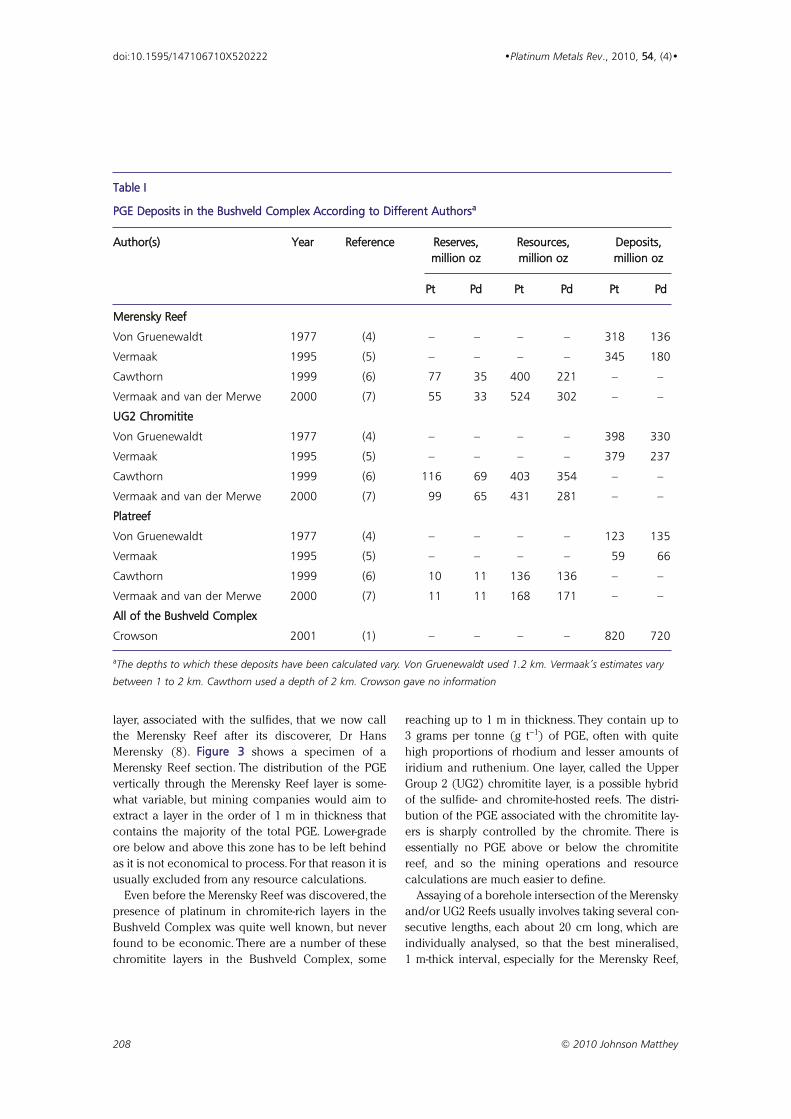
A number of estimates of the potential deposits of
the PGE in the Bushveld Complex have been pub-
lished in scientific journals over the last thirty years,
and the quoted numbers have not changed signifi-
cantly. A summary of these compilations is presented
in Table I (1, 4–7). These reports have come mainly
from South African-based geologists, and their figures
have been reproduced or validated by independent
organisations such as the United States Geological
Survey (USGS), that have staff qualified to make criti-
cal assessments of these estimates.
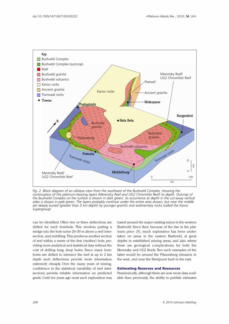
The Geology of the Bushveld ComplexBefore discussing how these estimates are calculated,
it is worth considering the origins and geology of the
Bushveld Complex. The economic potential of many
ore deposits is difficult to evaluate, but this is not so in
the case of the Bushveld ores. The Bushveld Complex
(see Figure 2) is an enormous irruption of magma
(molten rock) sourced deep within the Earth. The
extent of the magma flow was at least 300 km in diam-
eter. In the order of 1 million km3 of magma was
emplaced in a (geologically) very short period of
time. As this enormous volume of Bushveld magma
slowly cooled, different minerals began to solidify
and accumulated in thin, parallel layers at the bottom
of this huge magma ocean. The maximum thickness
ultimately was about 8 km.
Most minerals in the Bushveld Complex have no
economic importance, but two types are important
here: chromite and the sulfide group of minerals.
Both of these mineral types concentrate the PGE.
The first economically important discovery of plat-
inum in the Bushveld Complex was found in a single
207 © 2010 Johnson Matthey
doi:10.1595/147106710X520222 •Platinum Metals Rev., 2010, 54, (4)•
The South African Mineral Codes (SAMCODEs)
Rigorous definitions based on the South African Mineral Resource Committee (SAMREC) and South
African Mineral Asset Valuation (SAMVAL) codes (2, 3) can be found at www.samcode.co.za, but a very
simplified summary follows.
A mineral ‘rreesseerrvvee’ is an ore body for which adequate information exists to permit confident extraction.
Briefly, it requires that all aspects including adequately spaced drilling, assaying, mineralogical and metal-
lurgical studies, mine planning, beneficiation, environmental, social and legislative issues, and financial
viability have been addressed. Mining companies would typically plan their exploration and evaluation
strategies such that they had a minimum of ten years of ore in this category. (Two sub-categories exist:
‘probable’ and ‘proven’ reserves.)
A mineral ‘rreessoouurrccee’ is an ore body for which there are reasonable and realistic prospects for eventual
extraction. Addressing of all the issues listed under ‘rreesseerrvvee’ would have been initiated,and all such results
would be positive. Mining companies might aim to have a further ten years of ore in this category. (Three
sub-categories exist: ‘measured’, ‘indicated’ and ‘inferred’, as a function of increasing risk.)
No mining company is likely to incur major expense in exploration beyond the combined time period
of their reserves and resources of about twenty years, although completely new targets may be of interest
and land tenure and acquisition around existing operations will be carefully monitored.
The ore deposits of the Bushveld Complex are so large that they far exceed the time periods mentioned
above. Hence, to avoid any confusion (or over-optimistic extrapolations), the term ‘ddeeppoossiitt’ is used in this
report to indicate the continuing geological strata that contain ore mined in various areas.Reasonable geo-
logical information is available in these areas but no significant economic evaluation has been attempted.
Such strata are known to continue along surface between mines,and have been identified by geophysical
techniques to greater depth than current mining.
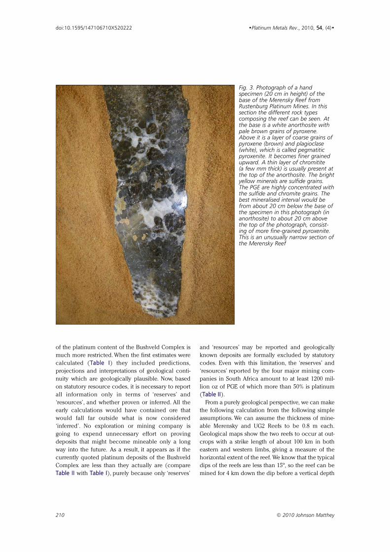
layer, associated with the sulfides, that we now call
the Merensky Reef after its discoverer, Dr Hans
Merensky (8). Figure 3 shows a specimen of a
Merensky Reef section. The distribution of the PGE
vertically through the Merensky Reef layer is some-
what variable, but mining companies would aim to
extract a layer in the order of 1 m in thickness that
contains the majority of the total PGE. Lower-grade
ore below and above this zone has to be left behind
as it is not economical to process. For that reason it is
usually excluded from any resource calculations.
Even before the Merensky Reef was discovered, the
presence of platinum in chromite-rich layers in the
Bushveld Complex was quite well known, but never
found to be economic. There are a number of these
chromitite layers in the Bushveld Complex, some
reaching up to 1 m in thickness. They contain up to
3 grams per tonne (g t−1) of PGE, often with quite
high proportions of rhodium and lesser amounts of
iridium and ruthenium. One layer, called the Upper
Group 2 (UG2) chromitite layer, is a possible hybrid
of the sulfide- and chromite-hosted reefs. The distri-
bution of the PGE associated with the chromitite lay-
ers is sharply controlled by the chromite. There is
essentially no PGE above or below the chromitite
reef, and so the mining operations and resource
calculations are much easier to define.
Assaying of a borehole intersection of the Merensky
and/or UG2 Reefs usually involves taking several con-
secutive lengths, each about 20 cm long, which are
individually analysed, so that the best mineralised,
1 m-thick interval, especially for the Merensky Reef,
208 © 2010 Johnson Matthey
doi:10.1595/147106710X520222 •Platinum Metals Rev., 2010, 54, (4)•
Table I
PGE Deposits in the Bushveld Complex According to Different Authorsaa
Author(s) Year Reference Reserves, Resources, Deposits,million oz million oz million oz
Pt Pd Pt Pd Pt Pd
Merensky Reef
Von Gruenewaldt 1977 (4) – – – – 318 136
Vermaak 1995 (5) – – – – 345 180
Cawthorn 1999 (6) 77 35 400 221 – –
Vermaak and van der Merwe 2000 (7) 55 33 524 302 – –
UG2 Chromitite
Von Gruenewaldt 1977 (4) – – – – 398 330
Vermaak 1995 (5) – – – – 379 237
Cawthorn 1999 (6) 116 69 403 354 – –
Vermaak and van der Merwe 2000 (7) 99 65 431 281 – –
Platreef
Von Gruenewaldt 1977 (4) – – – – 123 135
Vermaak 1995 (5) – – – – 59 66
Cawthorn 1999 (6) 10 11 136 136 – –
Vermaak and van der Merwe 2000 (7) 11 11 168 171 – –
All of the Bushveld Complex
Crowson 2001 (1) – – – – 820 720
aThe depths to which these deposits have been calculated vary. Von Gruenewaldt used 1.2 km. Vermaak’s estimates vary
between 1 to 2 km. Cawthorn used a depth of 2 km. Crowson gave no information
can be identified. Often two or three deflections are
drilled for each borehole. This involves putting a
wedge into the hole some 20–30 m above a reef inter-
section, and redrilling. This produces another section
of reef within a metre of the first (mother) hole, pro-
viding more analytical and statistical data without the
cost of drilling long, deep holes. Since many bore-
holes are drilled to intersect the reef at up to 2 km
depth such deflections provide more information
extremely cheaply. Over the many years of mining,
confidence in the statistical variability of reef inter-
sections permits reliable information on predicted
grade. Until ten years ago most such exploration was
based around the major existing mines in the western
Bushveld. Since then, because of the rise in the plat-
inum price (9), much exploration has been under-
taken on areas in the eastern Bushveld, at great
depths in established mining areas, and also where
there are geological complications, for both the
Merensky and UG2 Reefs. Two such examples of the
latter would be around the Pilanesberg intrusion in
the west, and near the Steelpoort fault in the east.
Estimating Reserves and ResourcesParadoxically, although there are now more data avail-
able than previously, the ability to publish estimates
209 © 2010 Johnson Matthey
doi:10.1595/147106710X520222 •Platinum Metals Rev., 2010, 54, (4)•
BBeellaa BBeellaa NNBBuurrggeerrssffoorrtt
MMiiddddeellbbuurrgg
PPrreettoorriiaa
MMookkooppaanneeTThhaabbaazziimmbbii
Karoo rocks
Platreef
Ancient granite
Transvaal rocks Transva
al rocks
Bushveldgranite
Bushveldgranite
Bushveld volcanics
Pilanesberg
km
0 100
Fig. 2. Block diagram of an oblique view from the southeast of the Bushveld Complex, showing thecontinuation of the platinum-bearing layers (Merensky Reef and UG2 Chromitite Reef) to depth. Outcrop ofthe Bushveld Complex on the surface is shown in dark green; its occurrence at depth in the cut-away verticalsides is shown in pale green. The layers probably continue under the entire area shown, but near the middleare deeply buried (greater than 5 km depth) by younger granitic and sedimentary rocks (called the KarooSupergroup)
Bushveld Complex Bushveld Complex (outcrop)ReefBushveld graniteBushveld volcanicsKaroo rocksAncient graniteTransvaal rocks
Merensky Reef/UG2 Chromitite Reef
Merensky Reef/UG2 Chromitite Reef
•• TToowwnnss
Key
km
0
10
of the platinum content of the Bushveld Complex is
much more restricted. When the first estimates were
calculated (Table I) they included predictions,
projections and interpretations of geological conti-
nuity which are geologically plausible. Now, based
on statutory resource codes, it is necessary to report
all information only in terms of ‘reserves’ and
‘resources’, and whether proven or inferred. All the
early calculations would have contained ore that
would fall far outside what is now considered
‘inferred’. No exploration or mining company is
going to expend unnecessary effort on proving
deposits that might become mineable only a long
way into the future. As a result, it appears as if the
currently quoted platinum deposits of the Bushveld
Complex are less than they actually are (compare
Table II with Table I), purely because only ‘reserves’
and ‘resources’ may be reported and geologically
known deposits are formally excluded by statutory
codes. Even with this limitation, the ‘reserves’ and
‘resources’ reported by the four major mining com-
panies in South Africa amount to at least 1200 mil-
lion oz of PGE of which more than 50% is platinum
(Table II).
From a purely geological perspective, we can make
the following calculation from the following simple
assumptions. We can assume the thickness of mine-
able Merensky and UG2 Reefs to be 0.8 m each.
Geological maps show the two reefs to occur at out-
crops with a strike length of about 100 km in both
eastern and western limbs, giving a measure of the
horizontal extent of the reef. We know that the typical
dips of the reefs are less than 15º, so the reef can be
mined for 4 km down the dip before a vertical depth
210 © 2010 Johnson Matthey
doi:10.1595/147106710X520222 •Platinum Metals Rev., 2010, 54, (4)•
Fig. 3. Photograph of a handspecimen (20 cm in height) of thebase of the Merensky Reef fromRustenburg Platinum Mines. In thissection the different rock typescomposing the reef can be seen. Atthe base is a white anorthosite withpale brown grains of pyroxene.Above it is a layer of coarse grains ofpyroxene (brown) and plagioclase(white), which is called pegmatiticpyroxenite. It becomes finer grainedupward. A thin layer of chromitite (a few mm thick) is usually present atthe top of the anorthosite. The brightyellow minerals are sulfide grains.The PGE are highly concentrated withthe sulfide and chromite grains. Thebest mineralised interval would befrom about 20 cm below the base ofthe specimen in this photograph (inanorthosite) to about 20 cm abovethe top of the photograph, consist-ing of more fine-grained pyroxenite.This is an unusually narrow section ofthe Merensky Reef
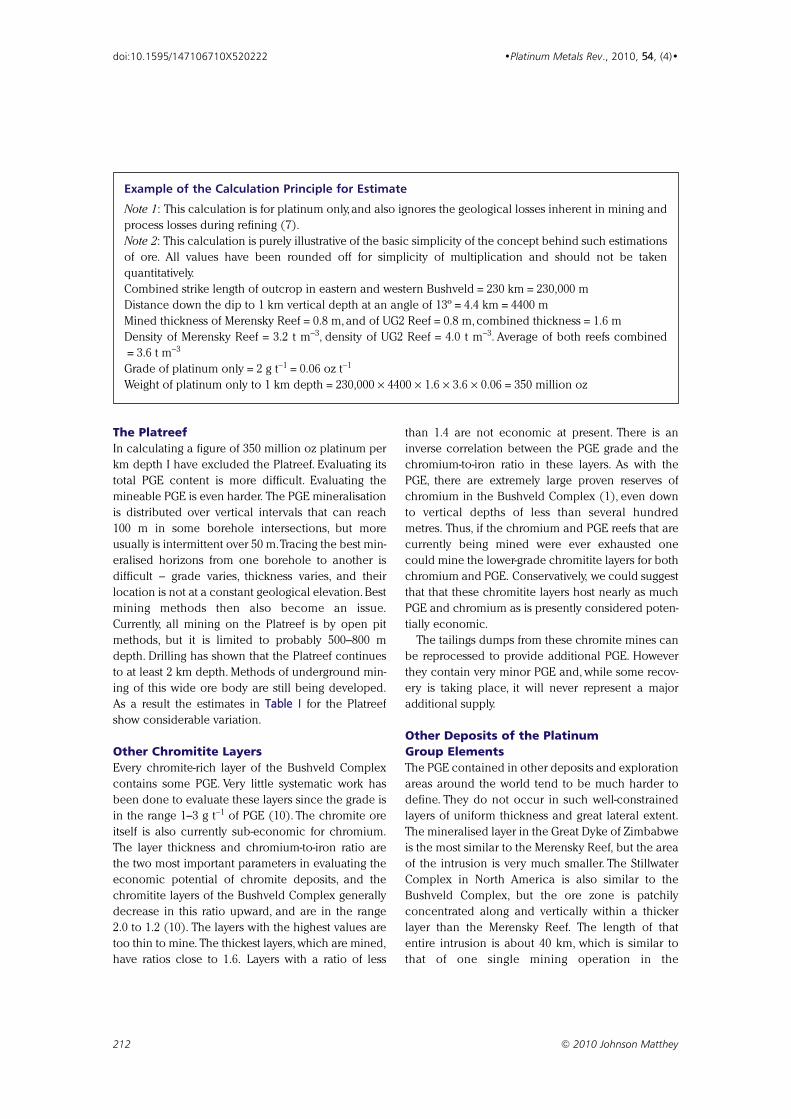
of 1 km is reached. The densities of Merensky and
UG2 Reefs are 3.2 t m−3 and 4.0 t m−3 respectively (7).
We can take a conservative grade of 2 g t−1 (0.06
oz t−1) of extractable platinum. Simple multiplication
of these figures (strike length along outcrop ×distance into the Earth × thickness × density ×grade, using appropriate units) yields 350 million oz
of platinum per km depth (see box below). I use this
method of presenting the information (in oz per km
depth) because it is not known what mining depths
may be ultimately viable. This simple calculation
ignores what are called geological losses (assorted
features such as faults and potholes, as described by
Vermaak and van der Merwe (7)). Taking a mining
depth to 2 km, and adding what might be present in
the Platreef which occurs in the northern limb of the
Bushveld Complex (see Figure 2), gives the rounded
figure of 800 million oz of platinum, similar to that
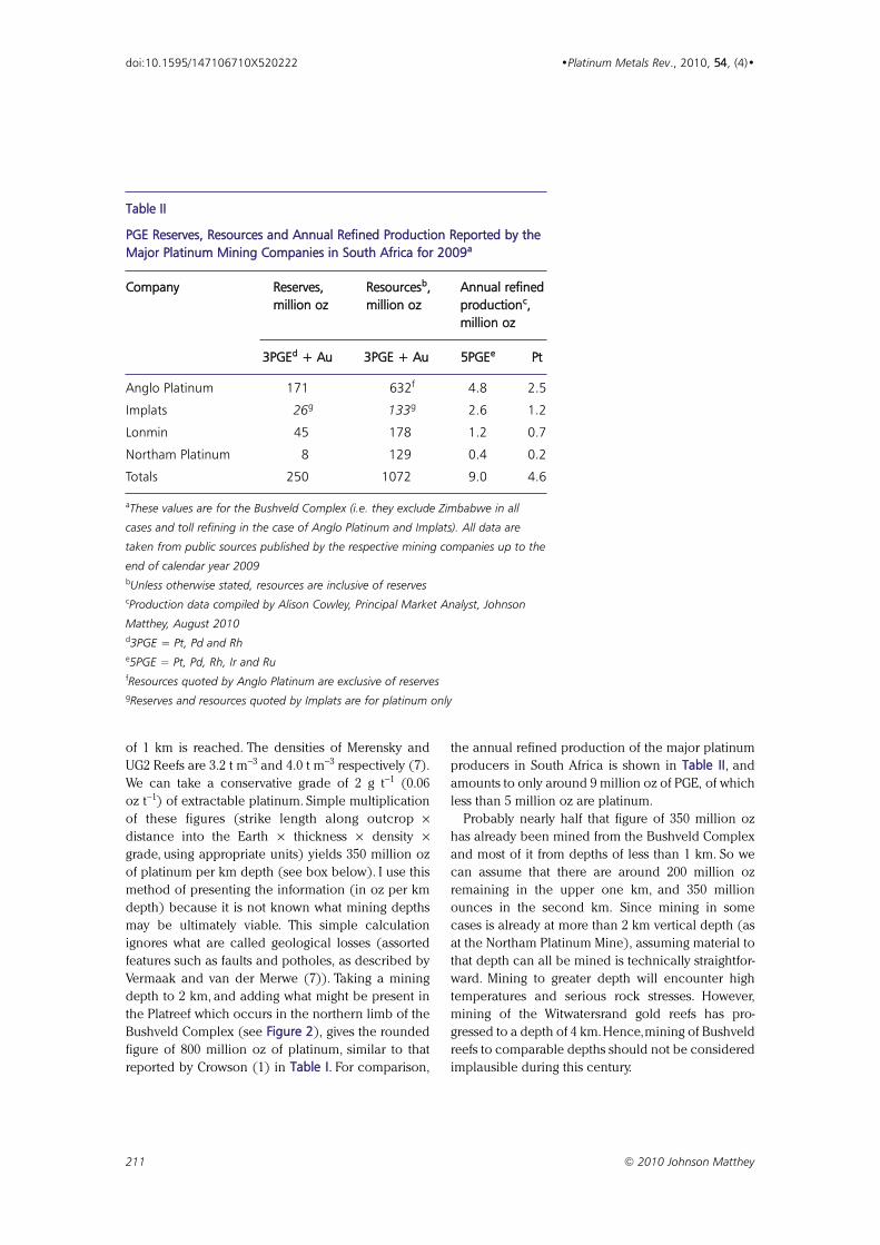
reported by Crowson (1) in Table I. For comparison,
the annual refined production of the major platinum
producers in South Africa is shown in Table II, and
amounts to only around 9 million oz of PGE, of which
less than 5 million oz are platinum.
Probably nearly half that figure of 350 million oz
has already been mined from the Bushveld Complex
and most of it from depths of less than 1 km. So we
can assume that there are around 200 million oz
remaining in the upper one km, and 350 million
ounces in the second km. Since mining in some
cases is already at more than 2 km vertical depth (as
at the Northam Platinum Mine), assuming material to
that depth can all be mined is technically straightfor-
ward. Mining to greater depth will encounter high
temperatures and serious rock stresses. However,
mining of the Witwatersrand gold reefs has pro-
gressed to a depth of 4 km. Hence,mining of Bushveld
reefs to comparable depths should not be considered
implausible during this century.
211 © 2010 Johnson Matthey
doi:10.1595/147106710X520222 •Platinum Metals Rev., 2010, 54, (4)•
Table II
PGE Reserves, Resources and Annual Refined Production Reported by theMajor Platinum Mining Companies in South Africa for 2009aa
Company Reserves, Resourcesbb, Annual refinedmillion oz million oz productioncc,
million oz
3PGEdd + Au 3PGE + Au 5PGEee Pt
Anglo Platinum 171 632f 4.8 2.5
Implats 26g 133g 2.6 1.2
Lonmin 45 178 1.2 0.7
Northam Platinum 8 129 0.4 0.2
Totals 250 1072 9.0 4.6
aThese values are for the Bushveld Complex (i.e. they exclude Zimbabwe in all
cases and toll refining in the case of Anglo Platinum and Implats). All data are
taken from public sources published by the respective mining companies up to the
end of calendar year 2009 bUnless otherwise stated, resources are inclusive of reservescProduction data compiled by Alison Cowley, Principal Market Analyst, Johnson
Matthey, August 2010 d3PGE = Pt, Pd and Rhe5PGE = Pt, Pd, Rh, Ir and RufResources quoted by Anglo Platinum are exclusive of reservesgReserves and resources quoted by Implats are for platinum only
The PlatreefIn calculating a figure of 350 million oz platinum per
km depth I have excluded the Platreef. Evaluating its
total PGE content is more difficult. Evaluating the
mineable PGE is even harder. The PGE mineralisation
is distributed over vertical intervals that can reach
100 m in some borehole intersections, but more
usually is intermittent over 50 m.Tracing the best min-
eralised horizons from one borehole to another is
difficult – grade varies, thickness varies, and their
location is not at a constant geological elevation. Best
mining methods then also become an issue.
Currently, all mining on the Platreef is by open pit
methods, but it is limited to probably 500–800 m
depth. Drilling has shown that the Platreef continues
to at least 2 km depth. Methods of underground min-
ing of this wide ore body are still being developed.
As a result the estimates in Table I for the Platreef
show considerable variation.
Other Chromitite LayersEvery chromite-rich layer of the Bushveld Complex
contains some PGE. Very little systematic work has
been done to evaluate these layers since the grade is
in the range 1–3 g t−1 of PGE (10). The chromite ore
itself is also currently sub-economic for chromium.
The layer thickness and chromium-to-iron ratio are
the two most important parameters in evaluating the
economic potential of chromite deposits, and the
chromitite layers of the Bushveld Complex generally
decrease in this ratio upward, and are in the range
2.0 to 1.2 (10). The layers with the highest values are
too thin to mine. The thickest layers, which are mined,
have ratios close to 1.6. Layers with a ratio of less
than 1.4 are not economic at present. There is an
inverse correlation between the PGE grade and the
chromium-to-iron ratio in these layers. As with the
PGE, there are extremely large proven reserves of
chromium in the Bushveld Complex (1), even down
to vertical depths of less than several hundred
metres. Thus, if the chromium and PGE reefs that are
currently being mined were ever exhausted one
could mine the lower-grade chromitite layers for both
chromium and PGE. Conservatively, we could suggest
that that these chromitite layers host nearly as much
PGE and chromium as is presently considered poten-
tially economic.
The tailings dumps from these chromite mines can
be reprocessed to provide additional PGE. However
they contain very minor PGE and, while some recov-
ery is taking place, it will never represent a major
additional supply.
Other Deposits of the PlatinumGroup ElementsThe PGE contained in other deposits and exploration
areas around the world tend to be much harder to
define. They do not occur in such well-constrained
layers of uniform thickness and great lateral extent.
The mineralised layer in the Great Dyke of Zimbabwe
is the most similar to the Merensky Reef, but the area
of the intrusion is very much smaller. The Stillwater
Complex in North America is also similar to the
Bushveld Complex, but the ore zone is patchily
concentrated along and vertically within a thicker
layer than the Merensky Reef. The length of that
entire intrusion is about 40 km, which is similar to
that of one single mining operation in the
212 © 2010 Johnson Matthey
doi:10.1595/147106710X520222 •Platinum Metals Rev., 2010, 54, (4)•
Example of the Calculation Principle for Estimate
Note 1: This calculation is for platinum only,and also ignores the geological losses inherent in mining and
process losses during refining (7).
Note 2: This calculation is purely illustrative of the basic simplicity of the concept behind such estimations
of ore. All values have been rounded off for simplicity of multiplication and should not be taken
quantitatively.
Combined strike length of outcrop in eastern and western Bushveld = 230 km = 230,000 m
Distance down the dip to 1 km vertical depth at an angle of 13º = 4.4 km = 4400 m
Mined thickness of Merensky Reef = 0.8 m, and of UG2 Reef = 0.8 m, combined thickness = 1.6 m
Density of Merensky Reef = 3.2 t m−3, density of UG2 Reef = 4.0 t m−3. Average of both reefs combined
= 3.6 t m−3
Grade of platinum only = 2 g t−1 = 0.06 oz t−1
Weight of platinum only to 1 km depth = 230,000 × 4400 × 1.6 × 3.6 × 0.06 = 350 million oz
Rustenburg area (Anglo Platinum, Impala Platinum
or Lonmin). The dip of the rocks in Stillwater is much
greater, again reducing the ore tonnage to maximum
mining depth.
The total potential of all the other PGE mining
areas is much harder to quantify because they are not
layered. Extensive exploration during the last ten
years has failed to produce any new major targets or
mines. Also, all occurrences in the Bushveld Complex
and Great Dyke have high platinum-to-palladium pro-
portions (platinum greater than palladium), whereas
all other occurrences in the world are dominated by
palladium.
Other IssuesMaintaining and increasing future production rates
represent significant challenges. Resolving social,
political and environmental issues, together with
ensuring water and electrical supply capacities, needs
ongoing monitoring and careful planning (11). These
challenges are the unknowns and unpredictables in
the future of platinum mining in South Africa, not the
availability of the ores.
ConclusionsThe estimates of the PGE presented here are not
intended to be rigorous or quantitative. They are
designed to show that the broad estimation of the
PGE in the Bushveld Complex is extremely easy to
make and to understand, and that the remarkably
disproportionate concentration of the PGE in one
geographic location, South Africa, is genuine. Even
with current mining methods, technology and prices,
there are many decades to a century of extractable
PGE ore already known in the Bushveld Complex.
With around 350 million oz of platinum per vertical
km depth, the enormous deposits of PGE in the
Bushveld Complex can be confidently relied upon to
provide a major proportion of the demand needs for
a long time into the future.
213 © 2010 Johnson Matthey
doi:10.1595/147106710X520222 •Platinum Metals Rev., 2010, 54, (4)•
Glossary
Term Definition
3PGE Platinum, palladium and rhodium
5PGE Platinum, palladium, rhodium, iridium and ruthenium
anorthosite A type of igneous rock largely composed of plagioclase feldspar, formed from
intrusions of magma within the Earth’s crust
beneficiation The processing of ore to produce minerals, also the further processing of
minerals to metals and then to value-added products
Bushveld Complex A large, layered, saucer-shaped geological formation found in the Bushveld
region of the north of South Africa; it contains deposits rich in PGE
chromite An iron chromium oxide (FeCr2O4) mineral with traces of magnesium and
aluminium
chromitite A rock type containing a high concentration of chromite
deflection A secondary borehole drilled at an angle to the vertical
deposit The total quantity of an ore body contained within a geological formation
dip The angle of inclination of a reef from the horizontal
fault A discontinuity in a layered feature resulting from rock fracture and movement,
with one section being displaced relative to another
feldspar An aluminium silicate mineral, containing potassium, sodium, calcium or barium
footwall The layer of rock beneath a vein or expanse of ore
grade The specific quantity of an element of interest contained within a unit mass of
an ore body; for the PGEs this is most often given in grams per metric tonne
Great Dyke A linear, layered geological feature running approximately north–south in the
centre of Zimbabwe; it contains deposits rich in PGE
214 © 2010 Johnson Matthey
doi:10.1595/147106710X520222 •Platinum Metals Rev., 2010, 54, (4)•
igneous Rocks formed from the solidification of either magma in the Earth’s crust or of
lava on the surface
Merensky Reef A layer of the Bushveld Complex largely composed of pyroxenite that is rich in
sulfide minerals; to date it has supplied most of the world’s platinum group
metals, and also yields significant quantities of copper, nickel, cobalt and gold as
byproducts. It is mined on both the eastern and western limbs of the Bushveld
Complex
mineralised horizon A layer or stratum in which minerals of interest are preferentially concentrated;
this could be distinct and continuous as a reef,or more dispersed and intermittent
outcrop A section of the reef which intersects the surface of the Earth and may have
been subject to weathering
pegmatite A type of igneous rock characterised by a very coarse grain structure, with
crystals several centimetres across usually composed of granite (quartz, feldspar
and mica)
PGE Platinum group elements (platinum, palladium, rhodium, iridium, osmium and
ruthenium).This term is used in geology as the elements generally occur in
mineral, rather than metallic, form within an ore
plagioclase An aluminium silicate mineral of the feldspar family, with varying relative
proportions of sodium and calcium
Platreef An ore body in the northern limb of the Bushveld Complex, it is the third largest
PGE deposit in the world, after the Merensky and UG2 Reefs. It consists of three
broadly mineralised horizons rather than a distinct reef
pothole Circular or elliptical sections where the reef has funnelled into the footwall,
leading to discontinuity and altered mineralogy
pyroxene Silicate minerals containing calcium, magnesium and iron
pyroxenite A rock type containing a high concentration of pyroxenes
reef A distinct and continuous layer or stratum in which minerals of interest are
preferentially concentrated
reserves Ore bodies which have been quantified to a high degree of confidence and
which can be extracted using existing methods
resources Ore bodies which are known to exist and which can be quantified to some
degree of confidence.These can reasonably be expected to be extracted in
the future
sedimentary A type of rock formed from solidified deposits of eroded rock material, which
have usually accumulated in bodies of water
strike The line of intersection of an inclined plane with the horizontal, such as when a
reef outcrops on the surface of the Earth
sulfide Minerals formed from compounds of sulfur, these are a major source of metals
such as copper, nickel and lead
tailings The waste material from ore processing, usually a slurry of finely ground rock in
water, from which most of the valuable minerals have been removed
UG2 Reef Upper Group 2; a layer of the Bushveld Complex rich in chromite but lacking
sulfide minerals. It possibly has a larger resource of platinum group elements
than the Merensky Reef. It lies below the Merensky Reef and is mined on both
the eastern and western limbs of the Bushveld Complex
215 © 2010 Johnson Matthey
doi:10.1595/147106710X520222 •Platinum Metals Rev., 2010, 54, (4)•
1 P. Crowson, “Minerals Handbook 2000–01: Statisticsand Analyses of the World’s Minerals Industry”, MiningJournal Books Ltd, Edenbridge, Kent, UK, 2001
2 The South African Code for the Reporting of ExplorationResults, Mineral Resources and Mineral Reserves (TheSAMREC Code), 2007 Edition as amended July 2009,Prepared by the South African Mineral ResourceCommittee (SAMREC) Working Group: http://www.samcode.co.za/ (Accessed on 27th July 2010)
3 The South African Code for the Reporting of MineralAsset Valuation (The SAMVAL Code), 2008 Edition asamended July 2009, Prepared by the South AfricanMineral Asset Valuation (SAMVAL) Working Group:http://www.samcode.co.za/ (Accessed on 27th July2010)
4 G. von Gruenewaldt, Miner. Sci. Eng., 1977, 9, (2), 83
5 C. F. Vermaak (Mintek, Randburg, South Africa), ‘ThePlatinum Group Metals: A Global Perspective’, Internalreport (unnumbered), 1995, ISBN 0-86999-926-5
6 R. G. Cawthorn, S. Afr. J. Sci., 1999, 95, (11/12), 481
7 C. F. Vermaak and M. J. van der Merwe (Mintek,Randburg, South Africa), ‘The Platinum Mines andDeposits of the Bushveld Complex, South Africa’, Internal
report (unnumbered), 1999, ISBN 0-86999-944-3
8 R. G. Cawthorn, Platinum Metals Rev., 2006, 50, (3), 130
9 Platinum Today, Current and Historical Prices: http://www.platinum.matthey.com/price-data (Accessed on27th July 2010)
10 R. N. Scoon and B. Teigler, Econ. Geol., 1994, 89, (5),1094
11 B. J. Glaister and G. M. Mudd, Miner. Eng., 2010, 23,(5), 438
The AuthorR. Grant Cawthorn is the Platinum Industry’sProfessor of Igneous Petrology at theUniversity of the Witwatersrand, South Africa.His main research interests are the genesis ofthe Bushveld Complex and its chromite,platinum and vanadiferous magnetitedeposits, and the Insizwa intrusion and itscopper and nickel deposits. His main fields ofspecialisation are the origin of mafic igneousintrusive rocks and their mineral deposits. Heholds a BSc from the University of Durham,UK, a PhD from the University of Edinburgh,UK, and a DSc from the University of theWitwatersrand, South Africa.
References
Reviewed by Timothy V. Johnson
Corning Environmental Technologies, Corning Incorporated,
HP-CB-2-4, Corning, NY 14831, USA;
EE--mmaaiill:: jjoohhnnssoonnttvv@@ccoorrnniinngg..ccoomm
The annual SAE Congress is the vehicle industry’s
largest conference and covers all aspects of automo-
tive engineering. The latest in the series was held in
Detroit, USA, from 13th–15th April, 2010. There were
upwards of a dozen sessions focused on vehicle emis-
sions technology, with most of them on diesel emis-
sions. More than 40 papers were presented on the
topic. Attendance was up relative to last year, with
most sessions having perhaps 100 attendees, but
some had more than 200. Of the attendees 86% were
from the US, of which 50% were from the Detroit area,
with 7% from Europe and 6% from Asia. Original
equipment manufacturers (OEMs) represented 23%
of attendees and 45% were part of the supply chain,
with 50% being involved in the automotive industry
and 35% working in the heavy-duty diesel sector.
This review focuses on key developments in diesel
emissions control from the conference. Papers can
be purchased and downloaded from the SAE web-
site (1). As in previous years, the diesel sessions were
opened with a review paper of key developments
from 2009 (2).
Selective Catalytic Reduction Technology
Selective catalytic reduction (SCR) is the leading
nitrogen oxides (NOx) emission control technology
for both heavy-duty and light-duty diesel applica-
tions. The field is advancing rapidly with new devel-
opments being reported on catalyst enhancements
and system improvements.
As engines become more efficient and regulators
become more concerned about low-load NOx emis-
sions, better low-temperature SCR system perform-
ance will be required. Currently good performance
is limited by urea injection issues (evaporation and
hydrolysis) at temperatures below 200ºC. Reggie
Zhan (Southwest Research Institute, USA) reported
on a new mixer that allows urea injections at temper-
atures as low as 180ºC and thus lowers NOx by about
30% over the US cold transient cycle, relative to no
mixer (3).
Pio Forzatti (Politenica di Milano, Italy) demon-
strated that ammonium nitrate (NH4NO3) injections
can substitute for nitrogen dioxide (NO2) to enhance
216 © 2010 Johnson Matthey
•Platinum Metals Rev., 2010, 5544, (4), 216–222•
SAE 2010 World CongressDiesel emissions control highlights of the annual Society of Automotive Engineers (SAE)international congress
doi:10.1595/147106710X526172 http://www.platinummetalsreview.com/
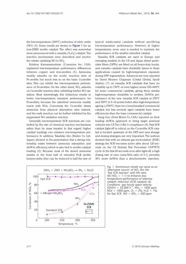
the low-temperature (200ºC) reduction of nitric oxide
(NO) (4). Some results are shown in FFiigguurree 11 for an
iron-ZSM5 zeolite catalyst. The effect was somewhat
more pronounced with a vanadia (V2O5) catalyst. The
reaction mechanisms were described and involve
the nitrate oxidising NO to NO2.
Krishna Kamasamudram (Cummins Inc, USA)
explained low-temperature performance differences
between copper- and iron-zeolites (5). Ammonia
readily adsorbs on the acidic reaction sites of
Fe-zeolite, but much less so on the basic Cu-zeolite
sites. This can inhibit the low-temperature perform-
ance of Fe-zeolites. On the other hand, NO2 adsorbs
on Cu-zeolite reaction sites, inhibiting further NO oxi-
dation. Most interestingly, this behaviour results in
better low-temperature transient performance for
Fe-zeolites, because the adsorbed ammonia readily
reacts with NOx. Conversely, the Cu-zeolite draws
ammonia from physical absorption sites instead,
and the early reaction can be further inhibited by the
suppressed NO oxidation reaction.
Generally, low-temperature SCR reactions are con-
trolled by the rate of chemical reaction mechanisms
rather than by mass transfer. In that regard, higher
catalyst loadings can enhance low-temperature per-
formance. In addition, Takahiko Ido (Ibiden Co Ltd,
Japan) showed in his presentation that a strong rela-
tionship exists between ammonia adsorption and
deNOx efficiency, which is also tied to zeolite catalyst
loading (6). Because most of the stored ammonia
resides in the front half of extruded Fe-β zeolite
honeycombs, they can be reduced to half the size of
typical washcoated catalysts without sacrificing
low-temperature performance. However, at higher
temperatures, more urea is needed to maintain the
performance of the smaller extruded catalyst.
Vanadia SCR catalysts are used in Europe and
emerging markets. In the US and Japan diesel partic-
ulate filters (DPFs) are fitted on all heavy-duty trucks,
and vanadia catalysts have durability issues in these
applications caused by high-temperature exposure
during DPF regeneration. Advances are now reported
by David Monroe Chapman (Cristal Global, Saudi
Arabia) (7) on vanadia SCR catalysts that have no
volatility up to 750ºC or even higher, versus 550–600ºC
for some commercial catalysts, giving them similar
high-temperature durability to zeolites. DeNOx per-
formance of the new vanadia SCR catalyst at 250ºC
and 350ºC is 5–10 points better after high-temperature
ageing (>700ºC) than for a benchmarked commercial
catalyst, but less severely aged catalysts have lower
efficiencies than the base commercial catalyst.
Gang Guo (Ford Motor Co, USA) reported on their
leading deNOx approach to bring larger personal
vehicles into US Tier 2 Bin 5 compliance (8). Fast SCR
catalyst light-off is critical, so the Cu-zeolite SCR cata-
lyst is located upstream of the DPF, and urea storage
and dosing strategies are very important.The authors
showed that with an exhaust gas recirculation (EGR)
strategy, the SCR becomes active after about 120 sec-
onds on the US Federal Test Procedure US-FTP75
cycle. In the first 60 seconds or so after light-off, a high
dosing rate of urea (urea:NOx ratio of 5:1) provides
30% more deNOx than a stoichiometric injection.
217 © 2010 Johnson Matthey
doi:10.1595/147106710X526172 •Platinum Metals Rev., 2010, 5544, (4)•
2NH3 + 2NO + NH4NO3 → 3N2 + 5H2O
Fast SCR
+340 ppm NH4NO3
Standard SCR
NH3
NH3
NOx
NOx
FFee--ZZSSMM55SSCCRR
α= 1
0 200 250 300 350
Temperature, ºC
Conve
rsio
n o
f N
Ox,
%
100
80
60
40
20
Fig. 1. Ammonium nitrate can serve as an‘alternative source’ of NO2 (for the ‘fast SCR reaction’ with the ratioNO:NO2 = 1:1) to enhance low-temperature performance of selective catalytic reduction (SCR) catalysts (4).Conditions: gas hourly space velocity(GHSV) = 33,000 h−1, NH3 = 1000 ppm,NOx = 1000 ppm, O2 = 2%, H2O = 1%;for fast SCR: NO = NO2 = 500 ppm
Ammonia slip can be an issue, so Cu-zeolite SCR cat-
alyst is added to the downstream DPF to capture and
utilise the ammonia. Regarding urea storage, injection
of 13 equivalents of urea provided 3 equivalents of
stored urea as measured by grams stored per litre of
catalyst at 100ºC, but this reduces to 1.5 equivalents at
200ºC. Ammonia stored in the entry sections of the
SCR catalyst is most critical to performance.
Finally, regulators have a concern about dioxin and
furan emissions when using Cu-zeolite catalysts. These
extremely toxic components can form if chlorine,
polyaromatic hydrocarbons (PAHs) and copper cata-
lyst are present together under exhaust conditions.
C. A. Laroo (US Environmental Protection Agency
(EPA)) made a presentation (no SAE paper available)
updating the industry on the EPA’s test programme to
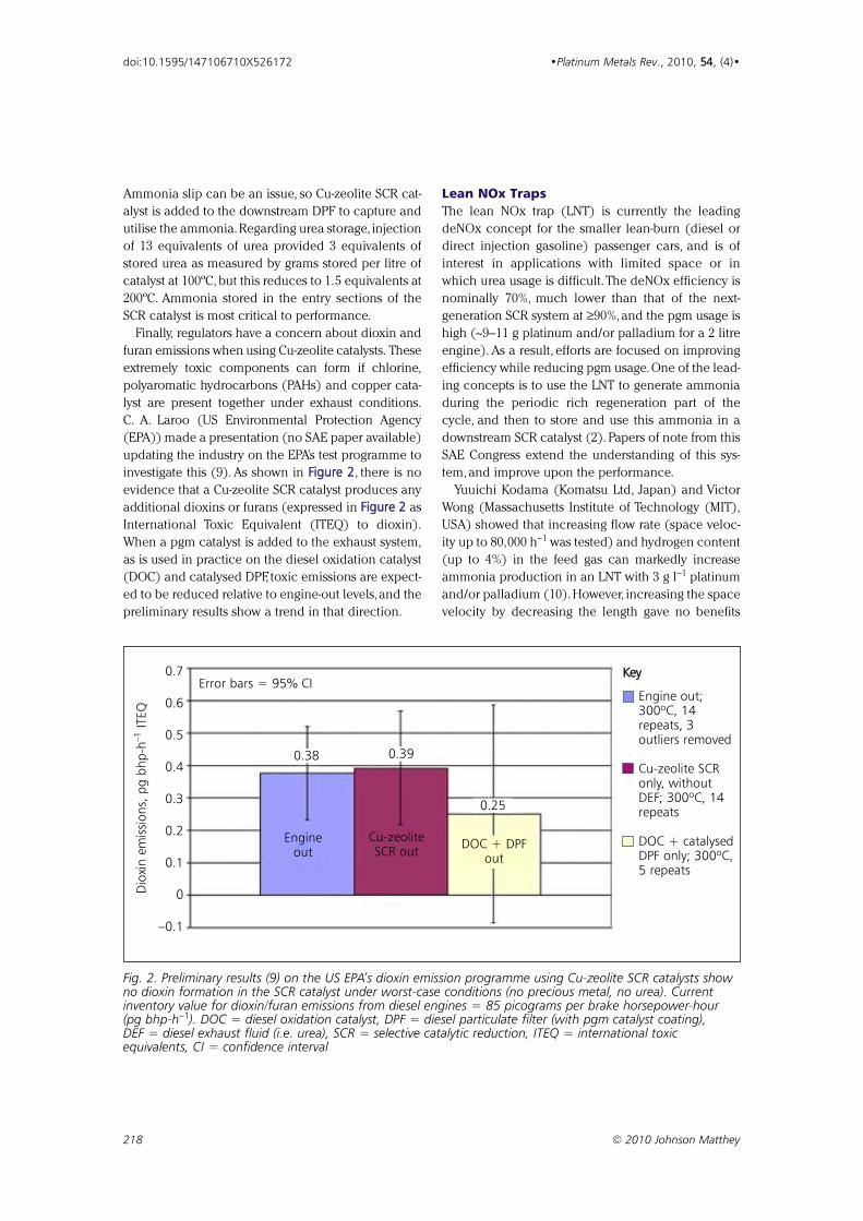
investigate this (9). As shown in FFiigguurree 22, there is no
evidence that a Cu-zeolite SCR catalyst produces any
additional dioxins or furans (expressed in FFiigguurree 22 as
International Toxic Equivalent (ITEQ) to dioxin).
When a pgm catalyst is added to the exhaust system,
as is used in practice on the diesel oxidation catalyst
(DOC) and catalysed DPF, toxic emissions are expect-
ed to be reduced relative to engine-out levels,and the
preliminary results show a trend in that direction.
Lean NOx Traps
The lean NOx trap (LNT) is currently the leading
deNOx concept for the smaller lean-burn (diesel or
direct injection gasoline) passenger cars, and is of
interest in applications with limited space or in
which urea usage is difficult.The deNOx efficiency is
nominally 70%, much lower than that of the next-
generation SCR system at ≥90%, and the pgm usage is
high (~9–11 g platinum and/or palladium for a 2 litre
engine). As a result, efforts are focused on improving
efficiency while reducing pgm usage. One of the lead-
ing concepts is to use the LNT to generate ammonia
during the periodic rich regeneration part of the
cycle, and then to store and use this ammonia in a
downstream SCR catalyst (2). Papers of note from this
SAE Congress extend the understanding of this sys-
tem, and improve upon the performance.
Yuuichi Kodama (Komatsu Ltd, Japan) and Victor
Wong (Massachusetts Institute of Technology (MIT),
USA) showed that increasing flow rate (space veloc-
ity up to 80,000 h−1 was tested) and hydrogen content
(up to 4%) in the feed gas can markedly increase
ammonia production in an LNT with 3 g l−1 platinum
and/or palladium (10). However, increasing the space
velocity by decreasing the length gave no benefits
218 © 2010 Johnson Matthey
doi:10.1595/147106710X526172 •Platinum Metals Rev., 2010, 5544, (4)•
0.7
0.6
0.5
0.4
0.3
0.2
0.1
0
–0.1
Dio
xin e
mis
sions,
pg b
hp
-h–1
ITEQ
Engineout
Cu-zeoliteSCR out
DOC + DPFout
0.38 0.39
0.25
Engine out;300ºC, 14repeats, 3outliers removed
Cu-zeolite SCRonly, withoutDEF; 300ºC, 14repeats
DOC + catalysedDPF only; 300ºC,5 repeats
KKeeyyError bars = 95% CI
Fig. 2. Preliminary results (9) on the US EPA’s dioxin emission programme using Cu-zeolite SCR catalysts showno dioxin formation in the SCR catalyst under worst-case conditions (no precious metal, no urea). Currentinventory value for dioxin/furan emissions from diesel engines = 85 picograms per brake horsepower-hour(pg bhp-h−1). DOC = diesel oxidation catalyst, DPF = diesel particulate filter (with pgm catalyst coating),DEF = diesel exhaust fluid (i.e. urea), SCR = selective catalytic reduction, ITEQ = international toxicequivalents, CI = confidence interval
beyond 50,000 h−1, conversely to results of the flow
studies. Further, the total system performance was
minimally affected by decreasing LNT length.
Hypotheses concerning ammonia and NOx reduc-
tion kinetics, rich-lean mixing interfaces, and oxygen
storage dynamics with length were proposed but not
investigated. Other factors impacting ammonia gen-
eration are residual oxygen in the rich gas (strong
negative impact), and longer rich times (positive
impact). The ratio of NO:NOx in the feed gas had
little impact. Water-gas shift reformers result in less
ammonia production, but improve system low-
temperature deNOx performance.
Lifeng Xu et al. (Ford Motor Co, USA) discovered
that other non-ammonia species formed in the LNT
can contribute to the downstream SCR performance
(11). The effect is more pronounced with less aggres-
sive LNT rich purges (less rich, shorter duration). In
one case with only two purges over a whole certifica-
tion test cycle, the system removed ~70% of the NOx
with the LNT accounting for most of it (50%), but
>80% of the SCR performance was attributed to the
non-ammonia species. The leading hypothesis is that
organo-nitrogen compounds, which may include iso-
cyanic acid (HNCO), form during the rich purge, and
are captured and utilised by the downstream SCR cat-
alyst. The researchers showed that a low-pgm LNT +
SCR system (3 g l−1 platinum and/or palladium on the
LNT) performs as well as a highly-loaded LNT (not
quantified, but 3.8 to 4.5 g l−1 platinum and/or
palladium is typical), either alone or with an SCR.
Cu-zeolite performs better than Fe-zeolite. Interestingly,
they looked at a variety of LNT and SCR configura-
tions (in series or alternating), and concluded that
the series arrangement is best due to faster LNT light-
off. On a vehicle, the system achieves ~97% deNOx
efficiency for a system roughly the same size as an
SCR-only system.
In another paper Joseph R. Theis (Ford Motor Co,
USA) investigated the ageing properties of the LNT +
SCR system (12). With constant LNT management,
the SCR advantage decreases if the LNT is aged for
4.5 hours at 700ºC versus the baseline of 600ºC
ageing. The effect is attributed to pgm ageing on the
LNT and less efficient ammonia production. Longer
rich periods as the system ages can counteract these
impacts. During LNT desulfation, the SCR effectively
oxidises hydrogen sulfide (H2S) and carbonyl sulfide
(COS) to sulfur dioxide (SO2).
Hai-Ying Chen (Johnson Matthey Inc,USA) reported
on further optimisation of both the LNT and the SCR
using NOx adsorber catalysts (NACs) (13). The LNT
was improved by decreasing the oxygen storage
capacity (OSC) and replacing 20% of the platinum in
the NAC with palladium. The results are shown in
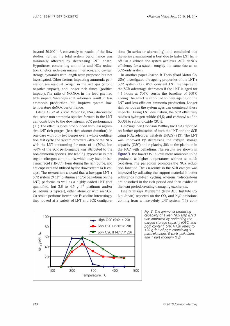
FFiigguurree 33. The lower OSC allows more ammonia to be
produced at higher temperatures without as much
oxidation. The palladium promotes the NOx reduc-
tion function. The Cu-zeolite in the SCR catalyst was
improved by adjusting the support material. It better
withstands rich-lean cycling, wherein hydrocarbons
are adsorbed in the rich period and then oxidise in
the lean period, creating damaging exotherms.
Finally, Tetsuya Murayama (New ACE Institute Co,
Ltd, Japan) reported on the CO2 and N2O emissions
coming from a heavy-duty LNT system (14) com-
219 © 2010 Johnson Matthey
doi:10.1595/147106710X526172 •Platinum Metals Rev., 2010, 5544, (4)•
100
80
60
40
20
0
NH
3yi
eld
, %
100 200 300 400 500
Temperature, ºC
High OSC (5:0:1/120)
Low OSC I (5:0:1/120)
Low OSC II (4:1:1/120)
Fig. 3. The ammonia producingcapability of a lean NOx trap (LNT)was improved by optimising theoxygen storage capacity (OSC) andpgm content. 5:0:1/120 refers to120 g ft−3 of pgm containing 5parts platinum, 0 parts palladium,and 1 part rhodium (13)
bined with an advanced engine with low NOx emis-
sions. About 3% of the global warming potential of
the exhaust comes from the N2O emitted by the LNT
during the rich period. Another 2.4% is attributed to
the fuel that is dosed to make a rich purge gas. The
balance, 94.6%, comes from the engine.
Diesel Particulate Filters
Although DPFs have been in commercial production
for original equipment manufacturer (OEM) applica-
tion for more than ten years,there is still much optimi-
sation activity in the field. Papers on DPF regeneration
dominated this part of the SAE Congress, with new
understanding on current and new regeneration
methods being gained.
James R.Warner (Ford Motor Co, USA) investigated
current DPF regeneration dynamics (15). Active
regeneration efficiency, wherein exhaust temperature
is increased to ~600ºC and the soot is burned by oxy-
gen, is not strongly dependent on oxygen content at
levels >2%, nor on whether the filter contains pgm,
although the pgm does oxidise the resultant CO to
form CO2. However, the efficiency is strongly depend-
ent on soot loading due to the build up of heat.
Passive regeneration, wherein the soot is oxidised by
NO2, is more than three times more effective at 370ºC
than at 485ºC, as the decomposition of NO2 back to
NO at the higher temperatures overwhelms the faster
soot oxidation rate at these temperatures. A DPF with
Cu-zeolite behaves similarly to the uncoated filter,
and has minimal impact on DPF regeneration.
Isocyanic acid (HNCO) is a byproduct of active
regeneration without catalyst, and needs to be taken
into account in the mass balance when examining
regeneration effectiveness. Active regeneration ‘costs’
about 0.5 miles per gallon (mpg) in terms of fuel
economy (2–3% fuel consumption), and passive
regeneration strategies can lower this penalty by
about 20%.
Direct oxidation catalysts have been of interest in
the field for more than five years (16, 17). These cata-
lysts use oxygen conducting materials (such as ceria,
zirconia or manganate) to burn the soot at the soot–
catalyst interface, rather than using oxygen in the gas
phase. Barry W. L. Southward (Umicore, Germany)
showed that a complex ceria material can begin
oxidising soot with model gas at 160ºC with comple-
tion at 220ºC using no or very little pgm (18). Once
started, the exotherm causes soot not in contact with
the catalyst to oxidise via the gas phase oxygen.When
tested using vehicle exhaust, the balance point tem-
perature (BPT, at which soot accumulation rate is the
same as the oxidation rate) is 20ºC lower than with a
commercial filter coated with 0.2 g l−1 of 1:1 platinum
and palladium (BPT = 420ºC). The regeneration effi-
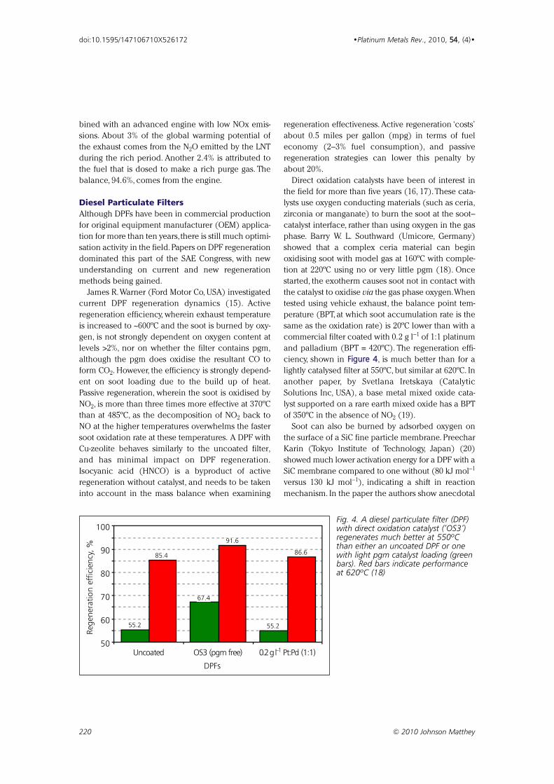
ciency, shown in FFiigguurree 44, is much better than for a
lightly catalysed filter at 550ºC, but similar at 620ºC. In
another paper, by Svetlana Iretskaya (Catalytic
Solutions Inc, USA), a base metal mixed oxide cata-
lyst supported on a rare earth mixed oxide has a BPT
of 350ºC in the absence of NO2 (19).
Soot can also be burned by adsorbed oxygen on
the surface of a SiC fine particle membrane. Preechar
Karin (Tokyo Institute of Technology, Japan) (20)
showed much lower activation energy for a DPF with a
SiC membrane compared to one without (80 kJ mol−1
versus 130 kJ mol−1), indicating a shift in reaction
mechanism. In the paper the authors show anecdotal
220 © 2010 Johnson Matthey
doi:10.1595/147106710X526172 •Platinum Metals Rev., 2010, 5544, (4)•
100
90
80
70
60
50
Reg
ener
ation e
ffic
iency
, %
Uncoated OS3 (pgm free) 0.2 g l–1 Pt:Pd (1:1)
55.2
85.4
67.4
91.6
55.2
86.6
Fig. 4. A diesel particulate filter (DPF)with direct oxidation catalyst (‘OS3’)regenerates much better at 550ºCthan either an uncoated DPF or onewith light pgm catalyst loading (greenbars). Red bars indicate performanceat 620ºC (18)
DPFs
221 © 2010 Johnson Matthey
doi:10.1595/147106710X526172 •Platinum Metals Rev., 2010, 5544, (4)•
evidence of the surface oxidation phenomenon, but
the presentation had new data confirming this mech-
anism using thermal desorption spectroscopy. In
another study, Takashi Mizutani (NGK Insulators Inc,
Japan) showed that ceramic membranes cause the
soot to deposit as a layer rather than being dispersed
throughout the porous wall of the DPF (21). This cre-
ates a more localised exotherm that improves regen-
eration efficiency by 10–15%.
In other developments worth noting, Gregory
Austin (Michigan Technological University, USA)
showed that soot formed from fuel containing 20%
biodiesel burns three times faster than soot from reg-
ular diesel (22).Also, Shohji Tsushima (Tokyo Institute
of Technology, Japan) demonstrated that very small
nanoparticles (1 nm), acting under Brownian diffu-
sion effects, are nearly all trapped in the surface
porosity of DPFs, while larger particles (>10 nm) are
trapped throughout the filter wall and may break
through (23).
Conclusions
High-efficiency deNOx systems are and will continue
to be a key area of development as regulations
tighten and engine fuel efficiency demands increase.
Cost reduction, primarily through better utilisation of
pgm, will also become important in future systems.
Addressing low-temperature NOx emissions is emerg-
ing as a future need. Low-temperature performance of
deNOx systems is enhanced by the presence of NO2,
but excessive amounts can result in higher emissions.
The design and management of pgm-containing sys-
tems can play a major role in this regard. In a similar
context, LNT systems seem to be yielding to LNT +
SCR systems, wherein pgm is removed from the LNT
to facilitate ammonia production for a downstream
SCR unit, in combination with a pgm-containing DOC
and DPF.
On DPFs, most work is being done on optimising
regeneration strategies to reduce fuel consumption
and cost. Most impactful to pgm use is the use of
direct oxidation catalysts based on ionic conducting
materials. Membranes are also evolving to improve
performance.
References1 SAE International: http://www.sae.org/ (Accessed on
27th September 2010)
2 T. V. Johnson, ‘Review of Diesel Emissions and Control’,
SAE Paper 2010-01-0301
3 R. Zhan, W. Li, S. T. Eakle and P. Weber, ‘Development of
a Novel Device to Improve Urea Evaporation, Mixing and
Distribution to Enhance SCR Performance’, SAE Paper
2010-01-1185
4 P. Forzatti, I. Nova and E. Tronconi, ‘Removal of NOx
from Diesel Exhausts: The New “Enhanced NH3-SCR”
Reaction’, SAE Paper 2010-01-1181
5 K. Kamasamudram, N. Currier, T. Szailer and A. Yezerets,
‘Why Cu- and Fe-Zeolite SCR Catalysts Behave Differently
at Low Temperatures’, SAE Paper 2010-10-1182
6 T. Ido, K. Yoshimura, M. Kunieda, Y. Tamura and
K. Ohno, ‘Volume Reduction of SCR Catalyst Using
Zeolite-Base Honeycomb Substrate’, SAE Paper 2010-
01-1170
7 D. M. Chapman, G. Fu, S. Augustine, J. Crouse, L. Zavalij,
M. Watson and D. Perkins-Banks, ‘New Titania Materials
with Improved Stability and Activity for Vanadia-Based
Selective Catalytic Reduction of NOx’, SAE Paper 2010-
01-1179
8 G. Guo, J. Warner, G. Cavataio, D. Dobson, E. Badillo
and C. Lambert, ‘The Development of Advanced Urea-
SCR Systems for Tier 2 Bin 5 and Beyond Diesel Vehicles’,
SAE Paper 2010-01-1183
9 C. A. Laroo, ‘EPA SCR Unregulated Emissions Test
Program: Dioxin, Furan, PCB and PAH Emissions from a
Compression Ignition Engine Utilizing CuZ SCR’, panel
presentation, SAE World Congress & Exhibition, Detroit,
MI, USA, 13th April, 2010
10 Y. Kodama and V. W. Wong, ‘Study of On-Board
Ammonia (NH3) Generation for SCR Operation’, SAE
Paper 2010-01-1071
11 L. Xu, R. McCabe, M. Dearth and W. Ruona, ‘Laboratory
and Vehicle Demonstration of “2nd-Generation” LNT +
in-situ SCR Diesel NOx Emission Control Systems’, SAE
Paper 2010-01-0305
12 J. R. Theis, J. Ura and R. McCabe, ‘The Effects of Sulfur
Poisoning and Desulfation Temperature on the NOx
Conversion of LNT + SCR Systems for Diesel Applications’,
SAE Paper 2010-01-0300
13 H.-Y. Chen, E. Weigert, J. Fedeyko, J. Cox and P. Andersen,
‘Advanced Catalysts for Combined (NAC + SCR) Emission
Control Systems’, SAE Paper 2010-01-0302
14 T. Murayama, Y. Aoyagi, M. Kobayashi, T. Adachi,
K. Shimada, H. Suzuki, Y. Goto and Y. Sato, ‘Effective
Usage of LNT in High Boosted and High EGR Rate of
Heavy Duty Diesel Engine’, SAE Paper 2010-01-1066
15 J. R. Warner, D. Dobson and G. Cavataio, ‘A Study of
Active and Passive Regeneration Using Laboratory
Generated Soot on a Variety of SiC Diesel Particulate
Filter Formulations’, SAE Paper 2010-01-0533
16 K. Harada, K. Suzuki, K. Okamoto, H. Yamada and
A. Takami, ‘Development of High Performance Catalyzed
DPF with New Soot Burning Mechanism’, Technical Paper
F2008-06-058, FISITA 2008 World Automotive Congress,
Munich, Germany, 14th–19th September, 2008

17 B. W. L. Southward and S. Basso, ‘An Investigation into
the NO2-Decoupling of Catalyst to Soot Contact and Its
Implications for Catalysed DPF Performance’, SAE Paper
2008-01-0481, SAE World Congress & Exhibition,
Detroit, MI, USA, 14th–17th April, 2008
18 B. W. L. Southward, S. Basso and M. Pfeifer, ‘On the
Development of Low PGM Content Direct Soot
Combustion Catalysts for Diesel Particulate Filters’, SAE
Paper 2010-01-0558
19 S. Iretskaya, S. Golden, T. Tadrous and S. H. Long, ‘PM
Control with Low NO2 Tailpipe Emissions by Systems
with Non-PGM Catalyzed DPF for Passive Soot
Regeneration’, SAE Paper 2010-01-0563
20 P. Karin and K. Hanamura, ‘Particulate Matter Trapping
and Oxidation on a Catalyst Membrane’, SAE Paper
2010-01-0808
21 T. Mizutani, S. Iwasaki, Y. Miyairi, K. Yuuki, M. Makino and
H. Kurachi, ‘Performance Verification of Next Generation
Diesel Particulate Filter’, SAE Paper 2010-01-0531
22 G. Austin, J. Naber, J. Johnson and C. Hutton, ‘Effects of
Biodiesel Blends on Particulate Matter Oxidation in a
Catalyzed Particulate Filter during Active Regeneration’,
SAE Paper 2010-01-0557
23 S. Tsushima, I. Nakamura, S. Sakashita, S. Hirai and
D. Kitayama, ‘Lattice Boltzmann Simulation on Particle
Transport and Captured Behaviours in a 3D-Reconstructed
Micro Porous DPF’, SAE Paper 2010-01-0534
The Reviewer
Timothy V. Johnson is Director – EmergingRegulations and Technologies for CorningEnvironmental Technologies, CorningIncorporated. Dr Johnson is responsiblefor tracking emerging mobile emissionsregulations and technologies, and helpsdevelop strategic positioning via newproducts.
222 © 2010 Johnson Matthey
doi:10.1595/147106710X526172 •Platinum Metals Rev., 2010, 5544, (4)•

By Koichi Matsutani*, Katsuichiro Hayakawaand Tomoyuki Tada
Tanaka Kikinzoku Kogyo KK, Technical Centre,2–73 Shinmachi, Hiratsuka, Kanagawa 254-0076,Japan;
*E-mmail: [email protected]
To investigate the effect of load cycling, platinum (Pt)
and platinum-cobalt (PtCo) fuel cell catalysts with
different particle sizes were prepared and evaluated for
their durability against load cycling. The particle size
of the Pt and PtCo catalysts was controlled by chang-
ing the catalyst loading and by applying heat treat-
ment. Pt catalysts with particle sizes of 2–3 nm and
4–5 nm and PtCo catalysts with sizes of 3–4 nm,
4–5 nm and 7–8 nm were obtained. A potential sweep
from 0.65 V to 1.05 V was applied to the cathode of
membrane electrode assemblies (MEAs) prepared
with these catalysts,and the degradation of their mass
activity and cell voltage were evaluated. As a result of
this investigation, it was found that Pt catalysts with
particle sizes of 4–5 nm and PtCo catalysts of particle
sizes 7–8 nm showed better stability against potential
sweep, with the Pt catalysts of sizes 4–5 nm showing
the best stability of all the catalysts tested.
1. IntroductionPolymer electrolyte membrane fuel cells (PEMFCs)
are becoming more attractive and practical as power
sources for automotive, small stationary and portable
applications. However, there are still some issues
which have to be overcome in order to realise the
full commercial potential of fuel cell systems. These
include improving the performance of the platinum-
based catalyst and its stability against load change
during fuel cell operation, improving the durability of
the support material and decreasing the overall cost
of the fuel cell system. Of these, improving catalyst sta-
bility in order to prevent catalyst degradation is one
of the most significant.
Several authors (1–3) have studied cathode cata-
lyst degradation during fuel cell operation by using
an accelerated degradation test, for example applying
a potential sweep or a series of potential steps to the
223 © 2010 Johnson Matthey
•Platinum Metals Rev., 2010, 54, (4), 223–232•
Effect of Particle Size of Platinum andPlatinum-Cobalt Catalysts on StabilityAgainst Load CyclingTowards the development of high performance, stable fuel cell catalysts withlow platinum loadings
doi:10.1595/147106710X523698 http://www.platinummetalsreview.com/
catalyst.Kinoshita et al.(1) reported that the decrease
in surface area of the catalyst was accelerated by the
application of a potential sweep in sulfuric acid solu-
tion. Patterson et al. (2) reported that the surface area
of the catalyst was reduced to half of its initial value
after a potential sweep of 6500 cycles from 0.87 V to
1.2 V in a PEMFC.Yu et al. (3) demonstrated a similar
experiment in which they reported that platinum
band formation in the membrane was observed for
both a platinum catalyst and a platinum-cobalt cata-
lyst after 2400 cycles of potential sweep.
Ferreira et al. (4) made a detailed investigation into
the MEA after potential sweep, and reported that the
degradation of the Pt catalyst was caused by the dis-
solution and redeposition of Pt, which leads to dis-
solved Pt being redeposited within the ionomer.
Makharia et al. (5) investigated the durability of the
carbon support at several voltages (1.0, 1.1, 1.2 and
1.3 V) and found that carbon weight loss is depend-
ent on the level of cell voltage.Weight loss increases
with increasing cell voltage. On the other hand,Tada
et al. (6) and Chen et al. (7) reported that a significant
decrease in catalyst surface area occurred even
under constant current operation.
The purpose of the present study was to improve
the stability of Pt and PtCo catalysts, especially
against load change. A potential sweep was applied
to the cathode to simulate load change during fuel
cell operation. To evaluate the stability of the catalyst,
MEA performance was measured before and after
potential sweep and the values were compared. Pt
and PtCo catalysts with different catalyst loadings
were tested. As a result of these investigations it was
found that changing the catalyst particle size by heat
treatment was the most effective method of stabilising
the catalyst. Here, the effect of the particle size of
Pt and PtCo catalysts on their stability against load
cycling is reported.
2. Experimental Details2.1 Catalyst PreparationThe Pt catalysts (denoted 30% Pt and 50% Pt in
Table I) were prepared by chemical deposition of Pt
in a water-based solution onto a high surface area
carbon support (surface area: 800 m2 g−1). The metal
loading of the catalysts was controlled at 30 wt% and
50 wt%. After the deposition of Pt, the catalysts were
well washed and dried out in an oven at 60ºC.
To control Pt particle size, heat treatment was then
applied to the 30% Pt and 50% Pt catalysts to produce
the heat-treated Pt catalysts (denoted 30% Pt-HT and
50% Pt-HT in Table I). Each catalyst was put into a
quartz tube and the tube was purged with nitrogen.
Then the tube was inserted into an electrical furnace
and heated up to 900ºC under reducing conditions
under a flow of hydrogen and nitrogen.The heat treat-
ment was applied to the catalyst for 30 minutes.
The PtCo alloy catalysts were prepared by chemical
deposition of Co onto the 30% Pt and 50% Pt catalysts
followed by heat treatment (these are denoted 30%
PtCo-HT and 50% PtCo-HT in Table I). The heat
treatment conditions were the same as those used
for the Pt catalysts. A PtCo catalyst with larger parti-
cle size (denoted 50% PtCo-HHT in Table I) was
prepared by higher-temperature heat treatment. After
the heat treatment, a leaching treatment with nitric
224 © 2010 Johnson Matthey
doi:10.1595/147106710X523698 •Platinum Metals Rev., 2010, 54, (4)•
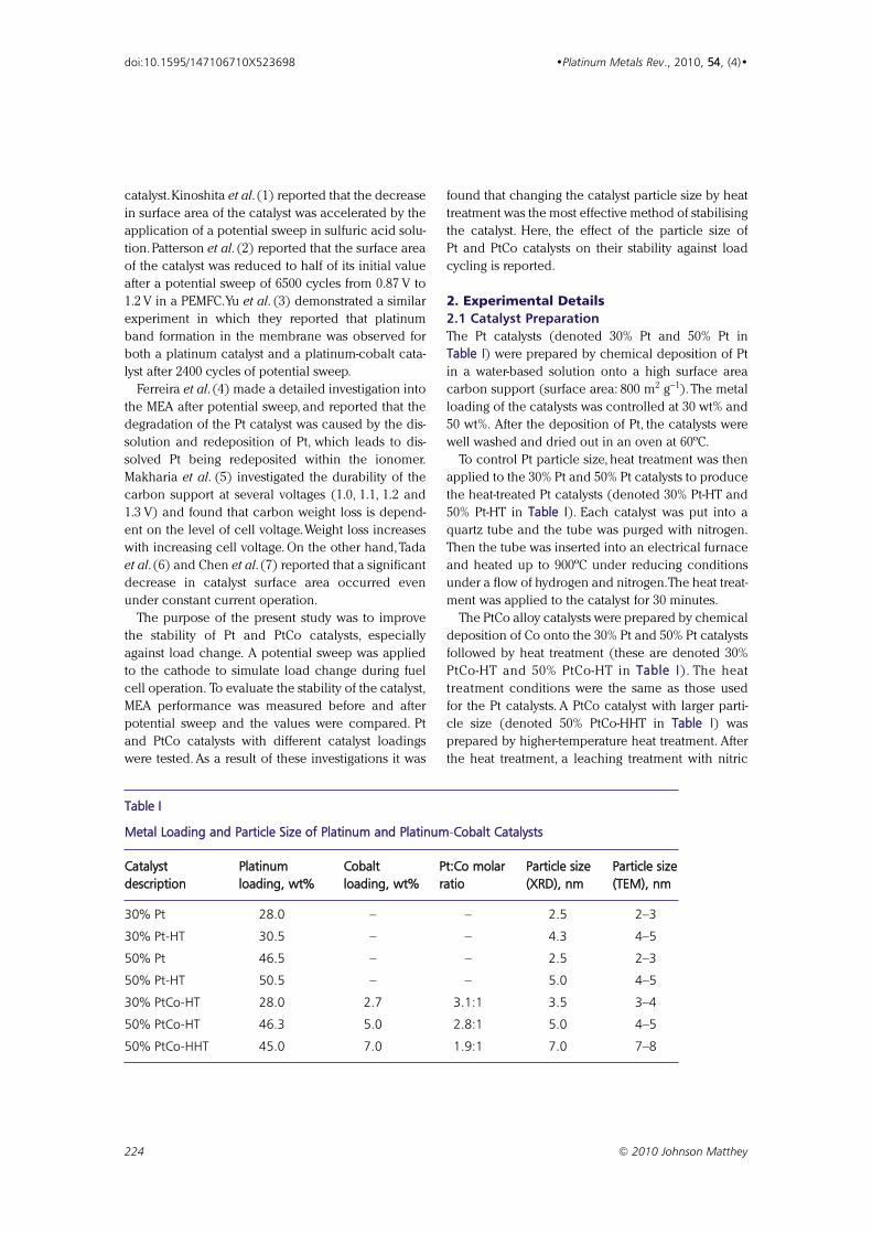
Table I
Metal Loading and Particle Size of Platinum and Platinum-CCobalt Catalysts
Catalyst Platinum Cobalt Pt:Co molar Particle size Particle size description loading, wt% loading, wt% ratio (XRD), nm (TEM), nm
30% Pt 28.0 – – 2.5 2–3
30% Pt-HT 30.5 – – 4.3 4–5
50% Pt 46.5 – – 2.5 2–3
50% Pt-HT 50.5 – – 5.0 4–5
30% PtCo-HT 28.0 2.7 3.1:1 3.5 3–4
50% PtCo-HT 46.3 5.0 2.8:1 5.0 4–5
50% PtCo-HHT 45.0 7.0 1.9:1 7.0 7–8
acid was carried out on each PtCo catalyst to remove
excess Co.
2.2 Catalyst CharacterisationTable I shows the metal loading and particle size of
the Pt and PtCo catalysts.The Pt loading of the Pt cat-
alysts was obtained by the ash method as follows:
about 0.1 g of catalyst sample was weighed and put
into a crucible. A lid was placed on the crucible
which was then placed in a muffle furnace. The tem-
perature was increased from room temperature to
800ºC and maintained for 1 hour to burn out all the
carbon support. After cooling to room temperature,
the crucible was weighed again. The Pt loading was
calculated from the initial sample weight and the
weight of the residue after burning out the carbon
support.
The total metal loadings of the PtCo catalysts were
also obtained by the ash method. The Pt:Co ratio of
each PtCo catalyst was obtained by X-ray fluores-
cence (XRF) analysis and used to calculate the
respective loadings of Pt and Co as shown in Table I.The average particle size of each catalyst was esti-
mated from transmission electron microscopy (TEM)
and X-ray diffraction (XRD). These values are also
shown in Table I.
2.3 Ink PreparationThe catalyst ink was prepared as follows. About 1 g of
catalyst powder containing 0.5 g of carbon was put
into a zirconia pot of volume 200 ml with 0.6 g of
ionomer (Nafion® DE521CS) powder, 18 ml of sol-
vents (1:1:1 water:n-propanol:2-propanol by volume)
and 200 g of 5 mm-diameter zirconia balls and mixed
by planetary ball milling for 50 minutes at 200 rpm
with a rotation:revolution ratio of 1:1. The carbon:
ionomer ratio in the ink was fixed at a dry weight ratio
of 1:1.2 for all catalysts. After storage for 3 days in a
refrigerator, the catalyst ink was used to prepare the
catalyst layer of the MEA.
2.4 Membrane Electrode Assembly PreparationThe gas diffusion layer was prepared by the following
two steps. First, a slurry containing a mixture of fluori-
nated ethylene-propylene (FEP) copolymer and car-
bon powder was printed onto carbon paper using a
bar coater, then dried and calcined. This layer works
as a hydrophobic layer. Second, a slurry containing a
mixture of Nafion® and carbon powder was printed
onto the carbon/FEP layer using the bar coater then
dried and hot pressed.This layer prevents penetration
of the catalyst ink into the gas diffusion layer during
coating of the catalyst layer.
Next, the catalyst ink was printed onto the gas dif-
fusion layer using the bar coater then dried and hot
pressed at 130ºC for 30 minutes with a pressure of
20 kg cm−2. The Pt loading of each electrode was
controlled at 0.4 mg cm−2 for the 30% catalysts and
0.5 mg cm−2 for the 50% catalysts by changing the
coating times and bar size. These electrodes were
used for the cathode. The anode was prepared in
the same manner using the 50% Pt catalyst. The Pt
loading of all anode catalyst layers was controlled at
0.5 mg cm−2.
A single fuel cell of area 25 cm2 was assembled by
sandwiching a membrane (Nafion® NRE212CS,
membrane thickness: 50 µm) with the anode and the
cathode using carbon plates with a single serpentine
gas flow channel. A schematic image of the cell is
shown in Figure 1. The compression was controlled
by a spring at 25 kg cm−2. No hot press was applied to
the MEA before assembling the single cell.
2.5 Membrane Electrode AssemblyMeasurementMEA measurement was carried out before and after
potential sweep to evaluate the catalyst stability. The
procedure was as follows:
(a) Measurement of initial MEA performance: after a
pretreatment, current–voltage (I–V) performance
and mass activity at 0.9 V were measured with
hydrogen (1000 standard cubic centimetres per
minute (sccm), fully humidified) and oxygen
(1000 sccm, dry) at 80ºC. Cyclic voltammetry was
also performed with hydrogen (50 sccm, fully
humidified) and nitrogen (20 sccm,dry) at a scan
rate of 10 mV sec−1 at the same temperature;
(b) Slow potential sweep: a potential sweep from
650 mV to 1050 mV was applied to the cathode
at 40 mV sec−1 for 3600 cycles (20 hours) at 80ºC
(to confirm whether the pretreatment was
sufficient);
(c) Measurement of MEA performance after slow
potential sweep: measurement of the MEA per-
formance and cyclic voltammetry were carried
out in the same way as described for step (a);
(d) Fast potential sweep: a potential sweep from
650 mV to 1050 mV was applied to the cathode
at 100 mV sec−1 for 10,800 cycles (24 hours)
at 80ºC;
225 © 2010 Johnson Matthey
doi:10.1595/147106710X523698 •Platinum Metals Rev., 2010, 54, (4)•
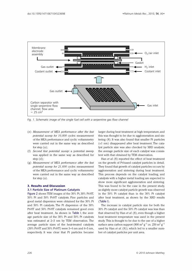
(e) Measurement of MEA performance after the fast
potential sweep for 10,800 cycles: measurement
of the MEA performance and cyclic voltammetry
were carried out in the same way as described
for step (a);
(f) Second fast potential sweep: a potential sweep
was applied in the same way as described for
step (d);
(g) Measurement of MEA performance after the fast
potential sweep for 21,600 cycles: measurement
of the MEA performance and cyclic voltammetry
were carried out in the same way as described
for step (a).
3. Results and Discussion3.1 Particle Size of Platinum CatalystsFigure 2 shows TEM images of the 30% Pt, 30% Pt-HT,
50% Pt and 50% Pt-HT catalysts. Fine particles and
good metal dispersion were obtained for the 30% Pt
and 50% Pt catalysts. The Pt dispersion of the 30%
Pt-HT and 50% Pt-HT catalysts remained good even
after heat treatment. As shown in Table I, the aver-
age particle size of the 30% Pt and 50% Pt catalysts
was estimated at 2–3 nm by TEM observation. The
average particle sizes of the heat-treated catalysts
(30% Pt-HT and 50% Pt-HT) were 3–4 nm and 4–5 nm,
respectively. It was clear that Pt particles became
larger during heat treatment at high temperature, and
this was thought to be due to agglomeration and sin-
tering (8). It was also found that smaller Pt particles
(<1 nm) disappeared after heat treatment. The cata-
lyst particle size was also checked by XRD analysis;
the average particle size of each catalyst was consis-
tent with that obtained by TEM observation.
Han et al. (8) reported the effect of heat treatment
on the growth of Pt-based catalyst particles in detail.
They found that growth of catalyst particles occurs by
agglomeration and sintering during heat treatment.
This process depends on the catalyst loading, and
catalysts with a higher metal loading are expected to
show more significant agglomeration and sintering.
This was found to be the case in the present study,
as slightly more catalyst particle growth was observed
in the 50% Pt catalyst than in the 30% Pt catalyst
after heat treatment, as shown by the XRD results
(Table I).
The increase in catalyst particle size for both the
30% Pt catalyst and the 50% Pt catalyst was less than
that observed by Han et al. (8), even though a higher
heat treatment temperature was used in the present
study. This is thought to be due to the use of a higher
surface area carbon support (800 m2 g−1 vs. 250 m2 g−1
used by Han et al. (8)), which led to a smaller num-
ber of catalyst particles per unit area.
226 © 2010 Johnson Matthey
doi:10.1595/147106710X523698 •Platinum Metals Rev., 2010, 54, (4)•
O2 /air inlet
H2 inlet
Coolant inlet
Gasket
Gas inlet
Gas outlet
Membraneelectrodeassembly
Carbon separator withsingle serpentine flowchannel; flow area = 25 cm2
Gas outlet
Coolant outlet
Fig. 1. Schematic image of the single fuel cell with a serpentine gas flow channel
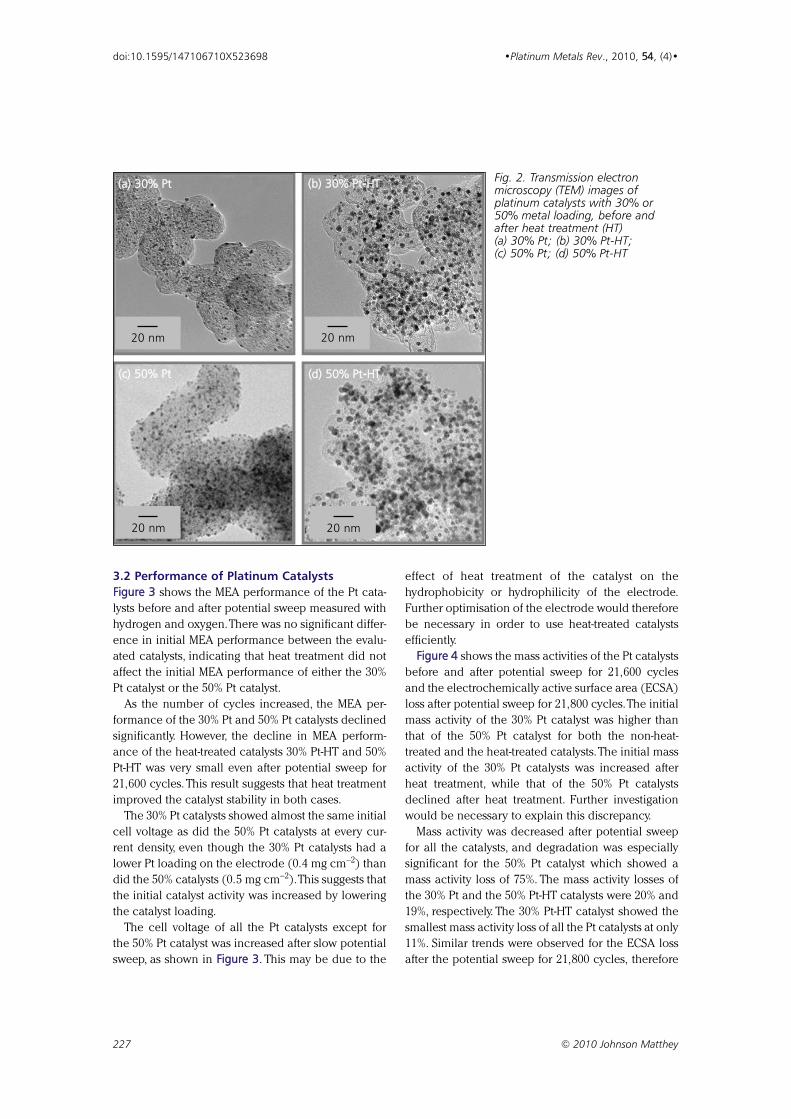
3.2 Performance of Platinum CatalystsFigure 3 shows the MEA performance of the Pt cata-
lysts before and after potential sweep measured with
hydrogen and oxygen.There was no significant differ-
ence in initial MEA performance between the evalu-
ated catalysts, indicating that heat treatment did not
affect the initial MEA performance of either the 30%
Pt catalyst or the 50% Pt catalyst.
As the number of cycles increased, the MEA per-
formance of the 30% Pt and 50% Pt catalysts declined
significantly. However, the decline in MEA perform-
ance of the heat-treated catalysts 30% Pt-HT and 50%
Pt-HT was very small even after potential sweep for
21,600 cycles. This result suggests that heat treatment
improved the catalyst stability in both cases.
The 30% Pt catalysts showed almost the same initial
cell voltage as did the 50% Pt catalysts at every cur-
rent density, even though the 30% Pt catalysts had a
lower Pt loading on the electrode (0.4 mg cm−2) than
did the 50% catalysts (0.5 mg cm−2).This suggests that
the initial catalyst activity was increased by lowering
the catalyst loading.
The cell voltage of all the Pt catalysts except for
the 50% Pt catalyst was increased after slow potential
sweep, as shown in Figure 3. This may be due to the
effect of heat treatment of the catalyst on the
hydrophobicity or hydrophilicity of the electrode.
Further optimisation of the electrode would therefore
be necessary in order to use heat-treated catalysts
efficiently.
Figure 4 shows the mass activities of the Pt catalysts
before and after potential sweep for 21,600 cycles
and the electrochemically active surface area (ECSA)
loss after potential sweep for 21,800 cycles.The initial
mass activity of the 30% Pt catalyst was higher than
that of the 50% Pt catalyst for both the non-heat-
treated and the heat-treated catalysts.The initial mass
activity of the 30% Pt catalysts was increased after
heat treatment, while that of the 50% Pt catalysts
declined after heat treatment. Further investigation
would be necessary to explain this discrepancy.
Mass activity was decreased after potential sweep
for all the catalysts, and degradation was especially
significant for the 50% Pt catalyst which showed a
mass activity loss of 75%. The mass activity losses of
the 30% Pt and the 50% Pt-HT catalysts were 20% and
19%, respectively. The 30% Pt-HT catalyst showed the
smallest mass activity loss of all the Pt catalysts at only
11%. Similar trends were observed for the ECSA loss
after the potential sweep for 21,800 cycles, therefore
227 © 2010 Johnson Matthey
doi:10.1595/147106710X523698 •Platinum Metals Rev., 2010, 54, (4)•
20 nm
(a) 30% Pt
20 nm
(b) 30% Pt-HT
20 nm
(c) 50% Pt
20 nm
(d) 50% Pt-HT
Fig. 2. Transmission electronmicroscopy (TEM) images ofplatinum catalysts with 30% or50% metal loading, before andafter heat treatment (HT)(a) 30% Pt; (b) 30% Pt-HT;(c) 50% Pt; (d) 50% Pt-HT
it may be supposed that the mass activity loss was
related to the decrease in ECSA.
3.3 Stability of Platinum CatalystsIn this study, a potential sweep from 0.65 V to 1.05 V
was applied to the cathode to accelerate catalyst
degradation. The upper voltage was limited to 1.05 V
in order to prevent carbon corrosion from affecting
the total performance degradation of the MEA.
Makharia et al. (5) reported the effect of voltage on
carbon weight loss. Based on their data, it was
expected that the carbon support would not be
damaged if the upper voltage was limited to 1.05 V.
Therefore, it was assumed that the catalyst degradation
observed in the present study was dominated only by
the dissolution and redeposition of Pt, as reported by
Ferreira et al. (4). Figure 3 shows that the degradation
of cell voltage could be controlled by heat treatment
of the Pt catalysts. This is thought to be due to a higher
initial surface area which reduces the possibility of
dissolution and redeposition of Pt and hence particle
size growth. In addition, the disappearance of very
fine Pt particles (less than 1 nm) may also have a sta-
bilising effect as these very fine particles are unstable.
228 © 2010 Johnson Matthey
doi:10.1595/147106710X523698 •Platinum Metals Rev., 2010, 54, (4)•
Current density, A cm–2
(a) 30% Pt
Cell
volta
ge, V
1.1
1.0
0.9
0.8
0.7
0.6
0.50 0.5 1 1.5
Current density, A cm–2
Cell
volta
ge, V
1.1
1.0
0.9
0.8
0.7
0.6
0.50 0.5 1 1.5
Current density, A cm–2
(c) 50% Pt
Cell
volta
ge, V
1.1
1.0
0.9
0.8
0.7
0.6
0.50 0.5 1 1.5
Current density, A cm–2
Cell
volta
ge, V
1.1
1.0
0.9
0.8
0.7
0.6
0.50 0.5 1 1.5
(b) 30% Pt-HT
(d) 50% Pt-HT
Fig. 3. Membrane electrode assembly (MEA) performance of platinum catalysts with 30% or 50% metalloading, before and after heat treatment (HT): (a) 30% Pt; (b) 30% Pt-HT; (c) 50% Pt; (d) 50% Pt-HT.Current–voltage performance measured with hydrogen and oxygen at 80ºC: before pretreatment ( ),after slow potential sweep ( ), after fast potential sweep for 10,800 cycles ( ), and after fast potential sweepfor 21,600 cycles ( ). Flow rate of H2/O2 was 1000/1000 sccm, humidity condition of H2/O2 was 90ºC/dry,gas pressure of H2/O2 was ambient
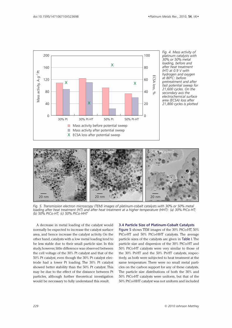
A decrease in metal loading of the catalyst would
normally be expected to increase the catalyst surface
area, and hence increase the catalyst activity. On the
other hand, catalysts with a low metal loading tend to
be less stable due to their small particle size. In this
study, however, little difference was observed between
the cell voltage of the 30% Pt catalyst and that of the
50% Pt catalyst, even though the 30% Pt catalyst elec-
trode had a lower Pt loading. The 30% Pt catalyst
showed better stability than the 50% Pt catalyst. This
may be due to the effect of the distance between Pt
particles, although further theoretical investigation
would be necessary to fully understand this result.
3.4 Particle Size of Platinum-Cobalt CatalystsFigure 5 shows TEM images of the 30% PtCo-HT, 50%
PtCo-HT and 50% PtCo-HHT catalysts. The average
particle sizes of the catalysts are given in Table I. The
particle size and dispersion of the 30% PtCo-HT and
50% PtCo-HT catalysts were very similar to those of
the 30% Pt-HT and the 50% Pt-HT catalysts, respec-
tively, as both were subjected to heat treatment at the
same temperature. There were no small metal parti-
cles on the carbon support for any of these catalysts.
The particle size distributions of both the 30% and
50% PtCo-HT catalysts were uniform, but that of the
50% PtCo-HHT catalyst was not uniform and included
229 © 2010 Johnson Matthey
doi:10.1595/147106710X523698 •Platinum Metals Rev., 2010, 54, (4)•
Mas
s ac
tivity
, A g
–1Pt
200
160
120
80
40
030% Pt 30% Pt-HT 50% Pt 50% Pt-HT
ECSA
loss, %
100
80
60
40
20
0
Mass activity before potential sweepMass activity after potential sweepECSA loss after potential sweepX
X
X
X
X
Fig. 4. Mass activity ofplatinum catalysts with30% or 50% metalloading, before andafter heat treatment(HT) at 0.9 V withhydrogen and oxygenat 80ºC: beforepretreatment and afterfast potential sweep for21,600 cycles. On thesecondary axis theelectrochemical surfacearea (ECSA) loss after21,800 cycles is plotted
20 nm
(a) 30% PtCo -HT
20 nm
(b) 50% PtCo-HT
20 nm
(c) 50% PtCo-HHT
Fig. 5. Transmission electron microscopy (TEM) images of platinum-cobalt catalysts with 30% or 50% metalloading after heat treatment (HT) and after heat treatment at a higher temperature (HHT): (a) 30% PtCo-HT;(b) 50% PtCo-HT; (c) 50% PtCo-HHT
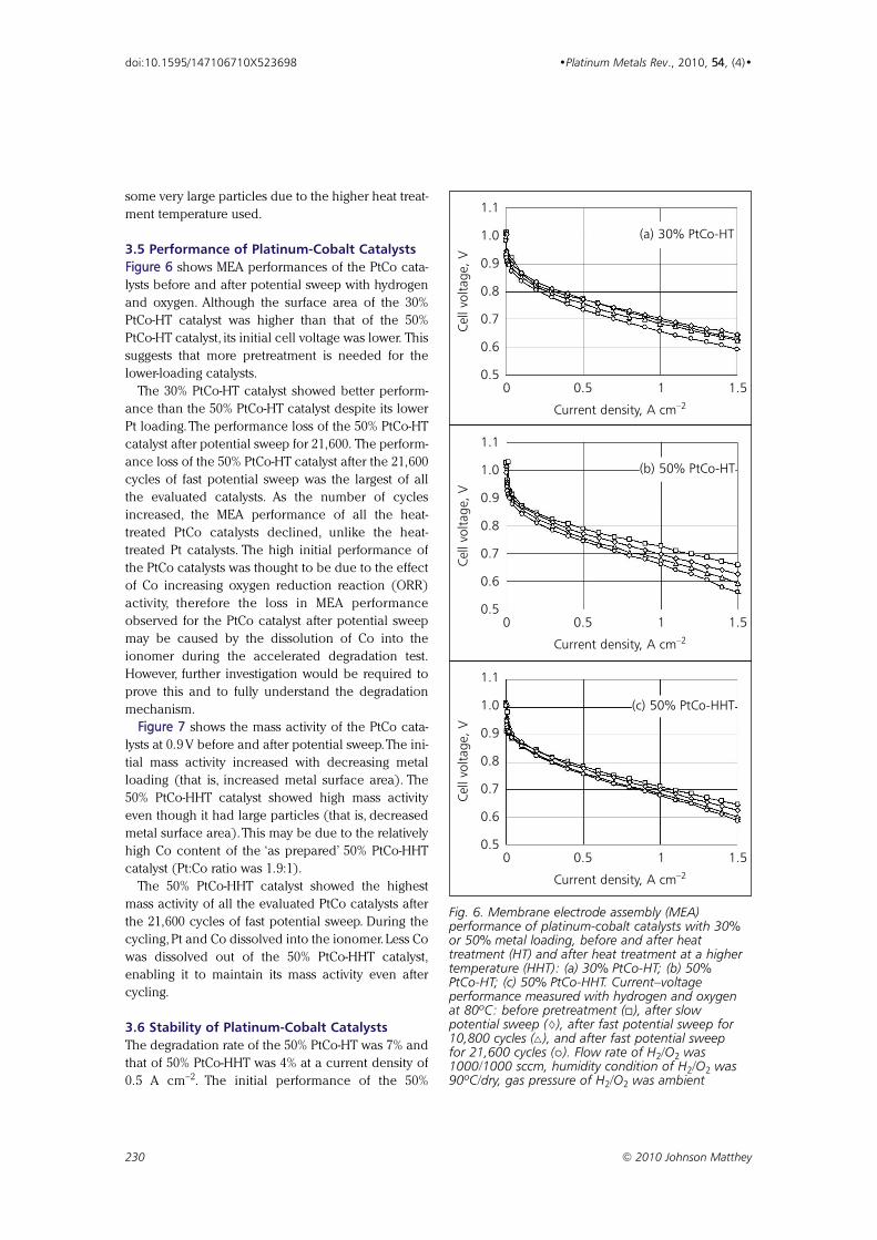
some very large particles due to the higher heat treat-
ment temperature used.
3.5 Performance of Platinum-Cobalt CatalystsFigure 6 shows MEA performances of the PtCo cata-
lysts before and after potential sweep with hydrogen
and oxygen. Although the surface area of the 30%
PtCo-HT catalyst was higher than that of the 50%
PtCo-HT catalyst, its initial cell voltage was lower. This
suggests that more pretreatment is needed for the
lower-loading catalysts.
The 30% PtCo-HT catalyst showed better perform-
ance than the 50% PtCo-HT catalyst despite its lower
Pt loading. The performance loss of the 50% PtCo-HT
catalyst after potential sweep for 21,600. The perform-
ance loss of the 50% PtCo-HT catalyst after the 21,600
cycles of fast potential sweep was the largest of all
the evaluated catalysts. As the number of cycles
increased, the MEA performance of all the heat-
treated PtCo catalysts declined, unlike the heat-
treated Pt catalysts. The high initial performance of
the PtCo catalysts was thought to be due to the effect
of Co increasing oxygen reduction reaction (ORR)
activity, therefore the loss in MEA performance
observed for the PtCo catalyst after potential sweep
may be caused by the dissolution of Co into the
ionomer during the accelerated degradation test.
However, further investigation would be required to
prove this and to fully understand the degradation
mechanism.
Figure 7 shows the mass activity of the PtCo cata-
lysts at 0.9 V before and after potential sweep.The ini-
tial mass activity increased with decreasing metal
loading (that is, increased metal surface area). The
50% PtCo-HHT catalyst showed high mass activity
even though it had large particles (that is, decreased
metal surface area). This may be due to the relatively
high Co content of the ‘as prepared’ 50% PtCo-HHT
catalyst (Pt:Co ratio was 1.9:1).
The 50% PtCo-HHT catalyst showed the highest
mass activity of all the evaluated PtCo catalysts after
the 21,600 cycles of fast potential sweep. During the
cycling, Pt and Co dissolved into the ionomer. Less Co
was dissolved out of the 50% PtCo-HHT catalyst,
enabling it to maintain its mass activity even after
cycling.
3.6 Stability of Platinum-Cobalt CatalystsThe degradation rate of the 50% PtCo-HT was 7% and
that of 50% PtCo-HHT was 4% at a current density of
0.5 A cm−2. The initial performance of the 50%
230 © 2010 Johnson Matthey
doi:10.1595/147106710X523698 •Platinum Metals Rev., 2010, 54, (4)•
Current density, A cm–2
(a) 30% PtCo-HT
Cell
volta
ge, V
1.1
1.0
0.9
0.8
0.7
0.6
0.50 0.5 1 1.5
Current density, A cm–2
(b) 50% PtCo-HTCe
ll vo
ltage
, V1.1
1.0
0.9
0.8
0.7
0.6
0.50 0.5 1 1.5
Current density, A cm–2
(c) 50% PtCo-HHT
Cell
volta
ge, V
1.1
1.0
0.9
0.8
0.7
0.6
0.50 0.5 1 1.5
Fig. 6. Membrane electrode assembly (MEA)performance of platinum-cobalt catalysts with 30%or 50% metal loading, before and after heattreatment (HT) and after heat treatment at a highertemperature (HHT): (a) 30% PtCo-HT; (b) 50%PtCo-HT; (c) 50% PtCo-HHT. Current–voltageperformance measured with hydrogen and oxygenat 80ºC: before pretreatment ( ), after slowpotential sweep ( ), after fast potential sweep for10,800 cycles ( ), and after fast potential sweepfor 21,600 cycles ( ). Flow rate of H2/O2 was1000/1000 sccm, humidity condition of H2/O2 was90ºC/dry, gas pressure of H2/O2 was ambient
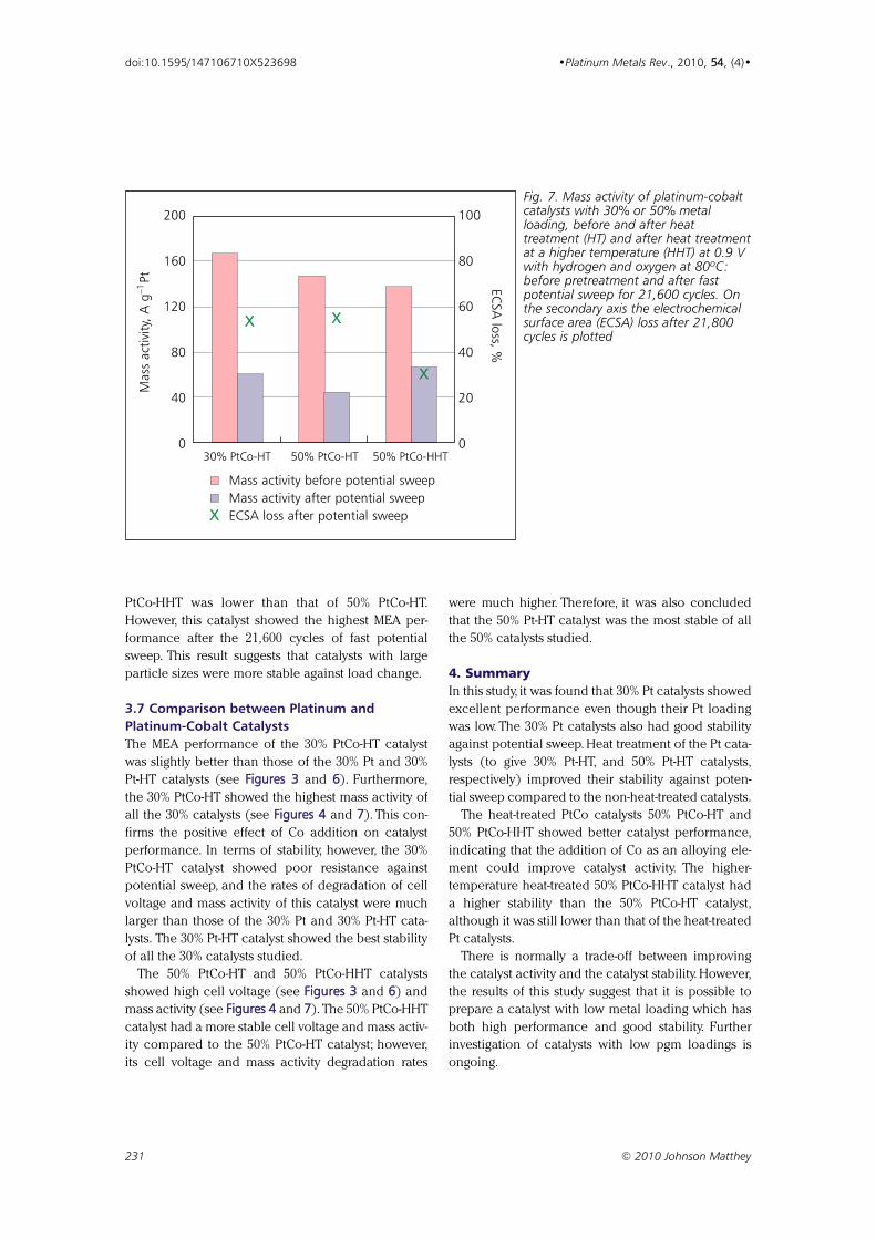
PtCo-HHT was lower than that of 50% PtCo-HT.
However, this catalyst showed the highest MEA per-
formance after the 21,600 cycles of fast potential
sweep. This result suggests that catalysts with large
particle sizes were more stable against load change.
3.7 Comparison between Platinum andPlatinum-Cobalt CatalystsThe MEA performance of the 30% PtCo-HT catalyst
was slightly better than those of the 30% Pt and 30%
Pt-HT catalysts (see Figures 3 and 6). Furthermore,
the 30% PtCo-HT showed the highest mass activity of
all the 30% catalysts (see Figures 4 and 7). This con-
firms the positive effect of Co addition on catalyst
performance. In terms of stability, however, the 30%
PtCo-HT catalyst showed poor resistance against
potential sweep, and the rates of degradation of cell
voltage and mass activity of this catalyst were much
larger than those of the 30% Pt and 30% Pt-HT cata-
lysts. The 30% Pt-HT catalyst showed the best stability
of all the 30% catalysts studied.
The 50% PtCo-HT and 50% PtCo-HHT catalysts
showed high cell voltage (see Figures 3 and 6) and
mass activity (see Figures 4 and 7). The 50% PtCo-HHT
catalyst had a more stable cell voltage and mass activ-
ity compared to the 50% PtCo-HT catalyst; however,
its cell voltage and mass activity degradation rates
were much higher. Therefore, it was also concluded
that the 50% Pt-HT catalyst was the most stable of all
the 50% catalysts studied.
4. SummaryIn this study, it was found that 30% Pt catalysts showed
excellent performance even though their Pt loading
was low. The 30% Pt catalysts also had good stability
against potential sweep. Heat treatment of the Pt cata-
lysts (to give 30% Pt-HT, and 50% Pt-HT catalysts,
respectively) improved their stability against poten-
tial sweep compared to the non-heat-treated catalysts.
The heat-treated PtCo catalysts 50% PtCo-HT and
50% PtCo-HHT showed better catalyst performance,
indicating that the addition of Co as an alloying ele-
ment could improve catalyst activity. The higher-
temperature heat-treated 50% PtCo-HHT catalyst had
a higher stability than the 50% PtCo-HT catalyst,
although it was still lower than that of the heat-treated
Pt catalysts.
There is normally a trade-off between improving
the catalyst activity and the catalyst stability. However,
the results of this study suggest that it is possible to
prepare a catalyst with low metal loading which has
both high performance and good stability. Further
investigation of catalysts with low pgm loadings is
ongoing.
231 © 2010 Johnson Matthey
doi:10.1595/147106710X523698 •Platinum Metals Rev., 2010, 54, (4)•
Mas
s ac
tivity
, A g
–1Pt
200
160
120
80
40
030% PtCo-HT 50% PtCo-HT 50% PtCo-HHT
ECSA
loss, %
100
80
60
40
20
0
X X
X
Mass activity before potential sweepMass activity after potential sweepECSA loss after potential sweepX
Fig. 7. Mass activity of platinum-cobaltcatalysts with 30% or 50% metalloading, before and after heattreatment (HT) and after heat treatmentat a higher temperature (HHT) at 0.9 Vwith hydrogen and oxygen at 80ºC:before pretreatment and after fastpotential sweep for 21,600 cycles. Onthe secondary axis the electrochemicalsurface area (ECSA) loss after 21,800cycles is plotted
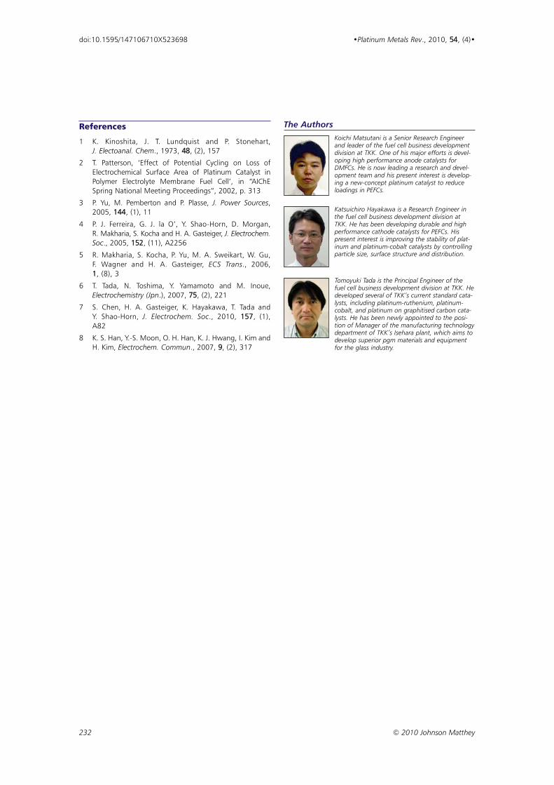
The AuthorsKoichi Matsutani is a Senior Research Engineerand leader of the fuel cell business developmentdivision at TKK. One of his major efforts is devel-oping high performance anode catalysts forDMFCs. He is now leading a research and devel-opment team and his present interest is develop-ing a new-concept platinum catalyst to reduceloadings in PEFCs.
Katsuichiro Hayakawa is a Research Engineer inthe fuel cell business development division atTKK. He has been developing durable and highperformance cathode catalysts for PEFCs. Hispresent interest is improving the stability of plat-inum and platinum-cobalt catalysts by controllingparticle size, surface structure and distribution.
Tomoyuki Tada is the Principal Engineer of thefuel cell business development division at TKK. Hedeveloped several of TKK’s current standard cata-lysts, including platinum-ruthenium, platinum-cobalt, and platinum on graphitised carbon cata-lysts. He has been newly appointed to the posi-tion of Manager of the manufacturing technologydepartment of TKK’s Isehara plant, which aims todevelop superior pgm materials and equipmentfor the glass industry.
References
1 K. Kinoshita, J. T. Lundquist and P. Stonehart,J. Electoanal. Chem., 1973, 48, (2), 157
2 T. Patterson, ‘Effect of Potential Cycling on Loss ofElectrochemical Surface Area of Platinum Catalyst inPolymer Electrolyte Membrane Fuel Cell’, in “AIChESpring National Meeting Proceedings”, 2002, p. 313
3 P. Yu, M. Pemberton and P. Plasse, J. Power Sources,2005, 144, (1), 11
4 P. J. Ferreira, G. J. la O’, Y. Shao-Horn, D. Morgan,R. Makharia, S. Kocha and H. A. Gasteiger, J. Electrochem.Soc., 2005, 152, (11), A2256
5 R. Makharia, S. Kocha, P. Yu, M. A. Sweikart, W. Gu,F. Wagner and H. A. Gasteiger, ECS Trans., 2006,1, (8), 3
6 T. Tada, N. Toshima, Y. Yamamoto and M. Inoue,Electrochemistry (Jpn.), 2007, 75, (2), 221
7 S. Chen, H. A. Gasteiger, K. Hayakawa, T. Tada andY. Shao-Horn, J. Electrochem. Soc., 2010, 157, (1),A82
8 K. S. Han, Y.-S. Moon, O. H. Han, K. J. Hwang, I. Kim andH. Kim, Electrochem. Commun., 2007, 9, (2), 317
232 © 2010 Johnson Matthey
doi:10.1595/147106710X523698 •Platinum Metals Rev., 2010, 54, (4)•
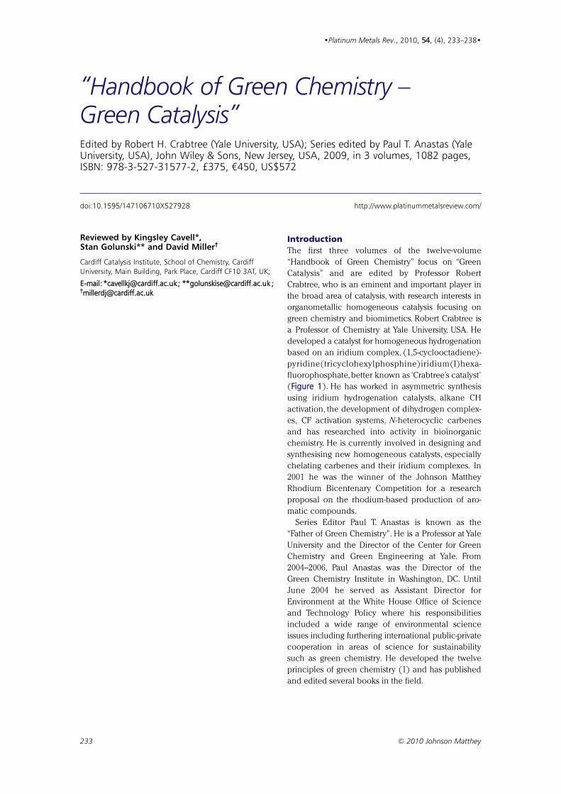
Reviewed by Kingsley Cavell*,Stan Golunski** and David Miller†
Cardiff Catalysis Institute, School of Chemistry, CardiffUniversity, Main Building, Park Place, Cardiff CF10 3AT, UK;
EE--mmaaiill:: **ccaavveellllkkjj@@ccaarrddiiffff..aacc..uukk;; ****ggoolluunnsskkiissee@@ccaarrddiiffff..aacc..uukk ;;††mmiilllleerrddjj@@ccaarrddiiffff..aacc..uukk
Introduction
The first three volumes of the twelve-volume
“Handbook of Green Chemistry” focus on “Green
Catalysis” and are edited by Professor Robert
Crabtree, who is an eminent and important player in
the broad area of catalysis, with research interests in
organometallic homogeneous catalysis focusing on
green chemistry and biomimetics. Robert Crabtree is
a Professor of Chemistry at Yale University, USA. He
developed a catalyst for homogeneous hydrogenation
based on an iridium complex, (1,5-cyclooctadiene)-
pyridine(tricyclohexylphosphine)iridium(I)hexa-
fluorophosphate,better known as ‘Crabtree’s catalyst’
(FFiigguurree 11). He has worked in asymmetric synthesis
using iridium hydrogenation catalysts, alkane CH
activation, the development of dihydrogen complex-
es, CF activation systems, N -heterocyclic carbenes
and has researched into activity in bioinorganic
chemistry. He is currently involved in designing and
synthesising new homogeneous catalysts, especially
chelating carbenes and their iridium complexes. In
2001 he was the winner of the Johnson Matthey
Rhodium Bicentenary Competition for a research
proposal on the rhodium-based production of aro-
matic compounds.
Series Editor Paul T. Anastas is known as the
“Father of Green Chemistry”. He is a Professor at Yale
University and the Director of the Center for Green
Chemistry and Green Engineering at Yale. From
2004–2006, Paul Anastas was the Director of the
Green Chemistry Institute in Washington, DC. Until
June 2004 he served as Assistant Director for
Environment at the White House Office of Science
and Technology Policy where his responsibilities
included a wide range of environmental science
issues including furthering international public-private
cooperation in areas of science for sustainability
such as green chemistry. He developed the twelve
principles of green chemistry (1) and has published
and edited several books in the field.
233 © 2010 Johnson Matthey
•Platinum Metals Rev., 2010, 5544, (4), 233–238•
“Handbook of Green Chemistry – Green Catalysis”Edited by Robert H. Crabtree (Yale University, USA); Series edited by Paul T. Anastas (YaleUniversity, USA), John Wiley & Sons, New Jersey, USA, 2009, in 3 volumes, 1082 pages,ISBN: 978-3-527-31577-2, £375, €450, US$572
doi:10.1595/147106710X527928 http://www.platinummetalsreview.com/
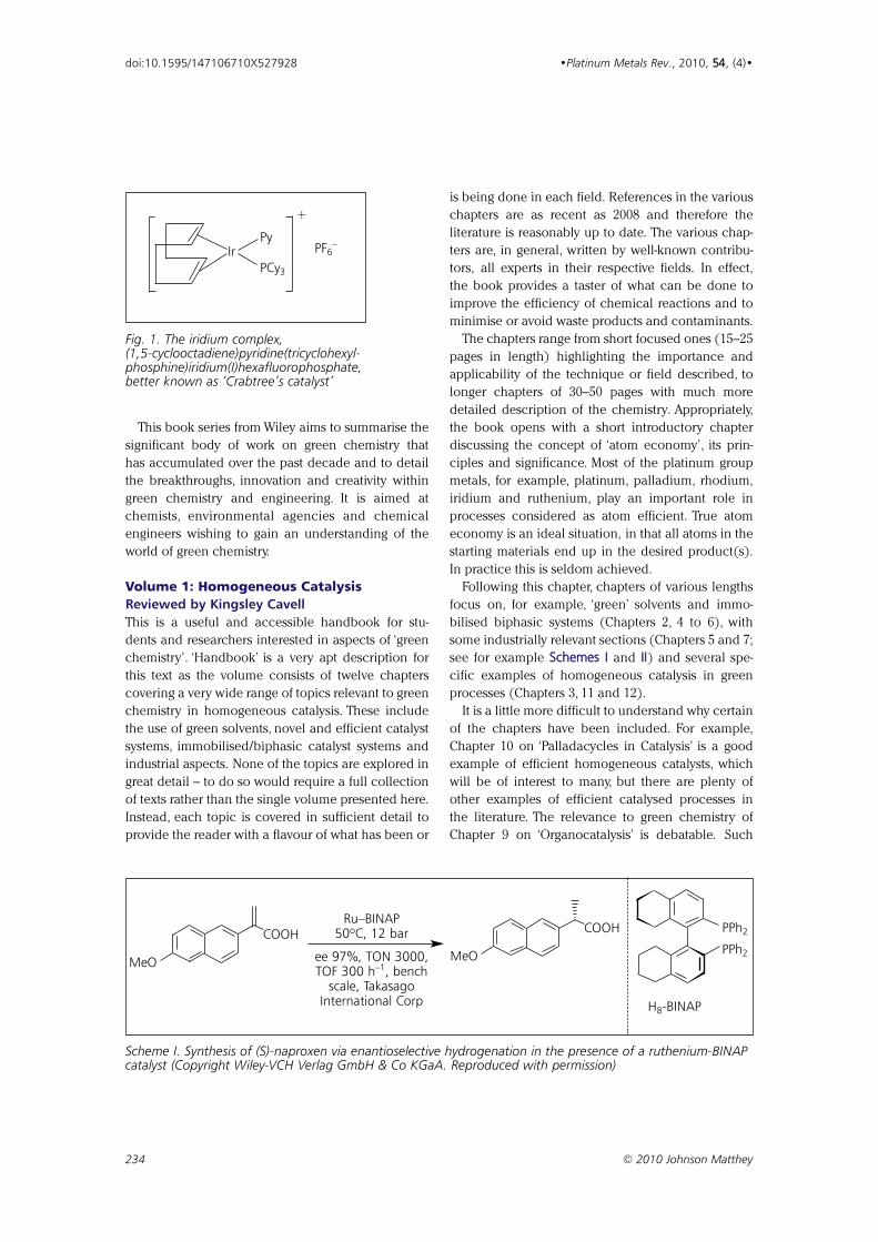
This book series from Wiley aims to summarise the
significant body of work on green chemistry that
has accumulated over the past decade and to detail
the breakthroughs, innovation and creativity within
green chemistry and engineering. It is aimed at
chemists, environmental agencies and chemical
engineers wishing to gain an understanding of the
world of green chemistry.
Volume 1: Homogeneous Catalysis
Reviewed by Kingsley Cavell
This is a useful and accessible handbook for stu-
dents and researchers interested in aspects of ‘green
chemistry’. ‘Handbook’ is a very apt description for
this text as the volume consists of twelve chapters
covering a very wide range of topics relevant to green
chemistry in homogeneous catalysis. These include
the use of green solvents, novel and efficient catalyst
systems, immobilised/biphasic catalyst systems and
industrial aspects. None of the topics are explored in
great detail – to do so would require a full collection
of texts rather than the single volume presented here.
Instead, each topic is covered in sufficient detail to
provide the reader with a flavour of what has been or
is being done in each field. References in the various
chapters are as recent as 2008 and therefore the
literature is reasonably up to date. The various chap-
ters are, in general, written by well-known contribu-
tors, all experts in their respective fields. In effect,
the book provides a taster of what can be done to
improve the efficiency of chemical reactions and to
minimise or avoid waste products and contaminants.
The chapters range from short focused ones (15–25
pages in length) highlighting the importance and
applicability of the technique or field described, to
longer chapters of 30–50 pages with much more
detailed description of the chemistry. Appropriately,
the book opens with a short introductory chapter
discussing the concept of ‘atom economy’, its prin-
ciples and significance. Most of the platinum group
metals, for example, platinum, palladium, rhodium,
iridium and ruthenium, play an important role in
processes considered as atom efficient. True atom
economy is an ideal situation, in that all atoms in the
starting materials end up in the desired product(s).
In practice this is seldom achieved.
Following this chapter, chapters of various lengths
focus on, for example, ‘green’ solvents and immo-
bilised biphasic systems (Chapters 2, 4 to 6), with
some industrially relevant sections (Chapters 5 and 7;
see for example SScchheemmeess II and IIII) and several spe-
cific examples of homogeneous catalysis in green
processes (Chapters 3, 11 and 12).
It is a little more difficult to understand why certain
of the chapters have been included. For example,
Chapter 10 on ‘Palladacycles in Catalysis’ is a good
example of efficient homogeneous catalysts, which
will be of interest to many, but there are plenty of
other examples of efficient catalysed processes in
the literature. The relevance to green chemistry of
Chapter 9 on ‘Organocatalysis’ is debatable. Such
234 © 2010 Johnson Matthey
doi:10.1595/147106710X527928 •Platinum Metals Rev., 2010, 5544, (4)•
MeO
COOH
MeO
COOH
PPh2
PPh2Ru–BINAP
50ºC, 12 bar
ee 97%, TON 3000, TOF 300 h–1, bench
scale, TakasagoInternational Corp H8-BINAP
Scheme I. Synthesis of (S)-naproxen via enantioselective hydrogenation in the presence of a ruthenium-BINAPcatalyst (Copyright Wiley-VCH Verlag GmbH & Co KGaA. Reproduced with permission)
PF6–
IrPy
PCy3
+
Fig. 1. The iridium complex,(1,5-cyclooctadiene)pyridine(tricyclohexyl-phosphine)iridium(I)hexafluorophosphate,better known as ‘Crabtree’s catalyst’
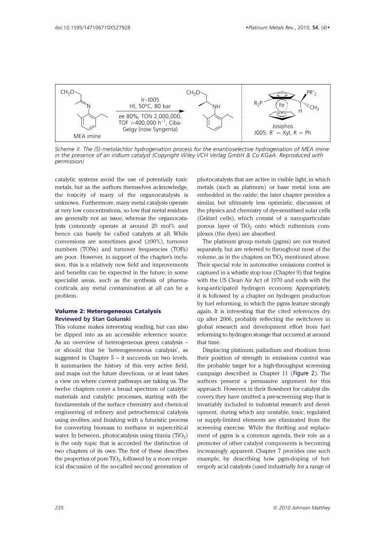
catalytic systems avoid the use of potentially toxic
metals, but as the authors themselves acknowledge,
the toxicity of many of the organocatalysts is
unknown. Furthermore, many metal catalysts operate
at very low concentrations, so low that metal residues
are generally not an issue, whereas the organocata-
lysts commonly operate at around 20 mol% and
hence can barely be called catalysts at all. While
conversions are sometimes good (≥90%), turnover
numbers (TONs) and turnover frequencies (TOFs)
are poor. However, in support of the chapter’s inclu-
sion, this is a relatively new field and improvements
and benefits can be expected in the future; in some
specialist areas, such as the synthesis of pharma-
ceuticals, any metal contamination at all can be a
problem.
Volume 2: Heterogeneous Catalysis
Reviewed by Stan Golunski
This volume makes interesting reading, but can also
be dipped into as an accessible reference source.
As an overview of heterogeneous green catalysis –
or should that be ‘heterogreeneous catalysis’, as
suggested in Chapter 5 – it succeeds on two levels.
It summarises the history of this very active field,
and maps out the future directions, or at least takes
a view on where current pathways are taking us. The
twelve chapters cover a broad spectrum of catalytic
materials and catalytic processes, starting with the
fundamentals of the surface chemistry and chemical
engineering of refinery and petrochemical catalysis
using zeolites, and finishing with a futuristic process
for converting biomass to methane in supercritical
water. In between, photocatalysis using titania (TiO2)
is the only topic that is accorded the distinction of
two chapters of its own. The first of these describes
the properties of pure TiO2, followed by a more empir-
ical discussion of the so-called second generation of
photocatalysts that are active in visible light, in which
metals (such as platinum) or base metal ions are
embedded in the oxide; the later chapter provides a
similar, but ultimately less optimistic, discussion of
the physics and chemistry of dye-sensitised solar cells
(Grätzel cells), which consist of a nanoparticulate
porous layer of TiO2 onto which ruthenium com-
plexes (the dyes) are absorbed.
The platinum group metals (pgms) are not treated
separately, but are referred to throughout most of the
volume, as in the chapters on TiO2 mentioned above.
Their special role in automotive emissions control is
captured in a whistle stop tour (Chapter 9) that begins
with the US Clean Air Act of 1970 and ends with the
long-anticipated hydrogen economy. Appropriately,
it is followed by a chapter on hydrogen production
by fuel reforming, in which the pgms feature strongly
again. It is interesting that the cited references dry
up after 2006, probably reflecting the switchover in
global research and development effort from fuel
reforming to hydrogen storage that occurred at around
that time.
Displacing platinum, palladium and rhodium from
their position of strength in emissions control was
the probable target for a high-throughput screening
campaign described in Chapter 11 (FFiigguurree 22). The
authors present a persuasive argument for this
approach. However, in their flowsheet for catalyst dis-
covery, they have omitted a pre-screening step that is
invariably included in industrial research and devel-
opment, during which any unstable, toxic, regulated
or supply-limited elements are eliminated from the
screening exercise. While the thrifting and replace-
ment of pgms is a common agenda, their role as a
promoter of other catalyst components is becoming
increasingly apparent. Chapter 7 provides one such
example, by describing how pgm-doping of het-
eropoly acid catalysts (used industrially for a range of
235 © 2010 Johnson Matthey
doi:10.1595/147106710X527928 •Platinum Metals Rev., 2010, 5544, (4)•
CH3O
N
MEA imine
CH3O
NH FeH
CH3
R2P
PR’2
JosiphosJ005: R’ = Xyl, R = Ph
Ir–J005HI, 50ºC, 80 bar
ee 80%, TON 2,000,000, TOF >400,000 h–1, Ciba-
Geigy (now Syngenta)
Scheme II. The (S)-metolachlor hydrogenation process for the enantioselective hydrogenation of MEA iminein the presence of an iridium catalyst (Copyright Wiley-VCH Verlag GmbH & Co KGaA. Reproduced withpermission)
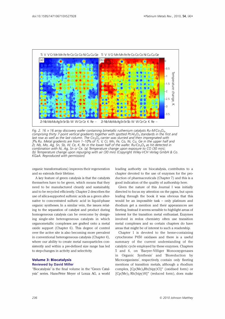
organic transformations) improves their regeneration
and so extends their lifetime.
A key feature of green catalysis is that the catalysts
themselves have to be green, which means that they
need to be manufactured cleanly and sustainably,
and to be recycled efficiently. Chapter 2 describes the
use of silica-supported sulfonic acids as a green alter-
native to concentrated sulfuric acid in liquid-phase
organic syntheses. In a similar vein, the issues relat-
ing to the separation of catalyst and product during
homogeneous catalysis can be overcome by design-
ing single-site heterogeneous catalysts in which
organometallic complexes are grafted onto a metal
oxide support (Chapter 6). This degree of control
over the active site is also becoming more prevalent
in conventional heterogeneous catalysis (Chapter 4),
where our ability to create metal nanoparticles con-
sistently and within a pre-defined size range has led
to step-changes in activity and selectivity.
Volume 3: Biocatalysis
Reviewed by David Miller
“Biocatalysis” is the final volume in the “Green Catal-
ysis” series. Hans-Peter Meyer of Lonza AG, a world
leading authority on biocatalysis, contributes to a
chapter devoted to the use of enzymes for the pro-
duction of pharmaceuticals (Chapter 7) and this is a
good indication of the quality of authorship here.
Given the nature of this Journal I was initially
directed to focus my attention on the pgms, but upon
leafing through the book it was obvious that this
would be an impossible task – only platinum and
rhodium get a mention and their appearances are
fleeting. Instead it seems sensible to highlight areas of
interest for the transition metal enthusiast. Enzymes
involved in redox chemistry often use transition
metal complexes and so certain chapters do have
areas that might be of interest to such a readership.
Chapter 1 is devoted to the heme-containing
cytochrome P450 oxidases and there is a useful
summary of the current understanding of the
catalytic cycle employed by these enzymes. Chapters
5 and 6, on ‘Baeyer- Villiger Monooxygenases
in Organic Synthesis’ and ‘Bioreduction by
Microorganisms’, respectively, contain only fleeting
mentions of transition metals, although a rhodium
complex, [Cp(Me)5Rh(bipy)Cl]+ (oxidised form) or
[Cp(Me)5 Rh(bipy)H]+ (reduced form), does make
236 © 2010 Johnson Matthey
doi:10.1595/147106710X527928 •Platinum Metals Rev., 2010, 5544, (4)•
Ti V V Cr Mn MnFe Fe Co Co Co Ni Cu Cu Ge Ti V V Cr Mn MnFe Fe Co Co Co Ni Cu Cu Ge
Zr Nb MoMoAg Sn Sn Sb W W Ce Ce K Re – Zr Nb MoMoAg Sn Sn Sb W W Ce Ce K Re –
0
–0.5
–1
–1.5
–2
–2.5
–3
–3.5
Temp
erature ch
ange, K
(a) (b)
Fig. 2. 16 × 16 array discovery wafer containing bimetallic ruthenium catalysts Ru-M/Co3O4 ,comprising thirty 7-point vertical gradients together with spotted Pt/Al2O3 standards in the first andlast row as well as the last column. The Co3O4 carrier was slurried and then impregnated with 3% Ru. Metal gradients are from 1–10% of Ti, V, Cr, Mn, Fe, Co, Ni, Cu, Ge in the upper half andZr, Nb, Mo, Ag, Sn, Sb, W, Ce, K, Re in the lower half of the wafer. Ru/Co3O4 as hit-detected incombination with Ni, Ag, Sn or Ce. (a) Temperature change upon exposure to CO (30 min);(b) Temperature change upon repurging with air (30 min) (Copyright Wiley-VCH Verlag GmbH & Co.KGaA. Reproduced with permission)
an appearance in Chapter 6; it is used to recycle
nicotinamide adenine dinucleotide reduced form
(NADH) at an electrode surface.
It is in Chapter 8 that this readership will find the
most interest. This is devoted to hydrogenases and
the hydrogen economy and there is a rich vein of
transition metal chemistry found therein. There we
meet enzymes that utilise iron-sulfur clusters, nickel-
iron and nickel-iron-selenium complexes plus many
of the techniques used to study their chemistry such
as electron paramagnetic resonance (EPR) and pro-
tein film voltammetry. In addition there are a number
of synthetic biomimetic metal complexes included.
The final chapter is devoted to bioremediation of
polyaromatic hydrocarbons and again, despite the
importance in this area of iron-containing dioxyge-
nase enzymes, there is little there for the inorganic
chemist to get excited about.
Despite the relative lack of interest to the inorganic
chemist, as a postgraduate level textbook on bio-
catalysis it stands up very well – its short length is
made up for with extensive and up to date referencing
and it includes subjects not covered in competing
books, such as the use of enzymes in the unusual
solvents supercritical CO2 and ionic liquids. It will
certainly be a valuable addition to this reviewer’s
book collection.
237 © 2010 Johnson Matthey
doi:10.1595/147106710X527928 •Platinum Metals Rev., 2010, 5544, (4)•
Concluding Remarks
This three-volume set of books covers a wide range of
topics within homogeneous, heterogeneous and bio-
catalysis, with contributions from well-known names
in their respective fields. Overall, the books provide
an overview of processes and reactions that can be
considered ‘green’, with indications of where current
directions in research may be going. The role of tran-
sition metals including the pgms within this area
seems assured.
Future volumes of Wiley’s “Handbook of Green
Chemistry” will focus on “Green Solvents”, “Green
Processes” and “Green Products”. They will appear as
three further sets of three volumes each and are
expected to be published by 2012 (2).
References
1 P. T. Anastas and J. C. Warner, “Green Chemistry: Theoryand Practice”, Oxford University Press, New York, USA,1998, p. 30
2 Wiley, Handbook of Green Chemistry, 12 volume set,Series Editor Paul T. Anastas, ISBN: 978-3-527-31404-1:http://eu.wiley.com/WileyCDA/WileyTitle/productCd-3527314040,descCd-tableOfContents.html (Accessedon 26th August 2010)
“Handbook of Green Chemistry – Green Catalysis”Volume 1: Homogeneous CatalysisVolume 2: Heterogeneous CatalysisVolume 3: Biocatalysis
The Reviewers
238 © 2010 Johnson Matthey
doi:10.1595/147106710X527928 •Platinum Metals Rev., 2010, 5544, (4)•
The Cardiff Catalysis Institute
The recently established Cardiff Catalysis Institute combines expertise from the seven main research
groups within the School of Chemistry of Cardiff University: Chemical Biology; Heterogeneous Catalysis and
Surface Science; Inorganic Chemistry; Organic Synthesis; Solid State and Materials Chemistry; Theoretical
and Computational Chemistry; Physical Organic Chemistry. Consisting of close to 100 researchers, its aim
is to be an industrially-facing academic centre of excellence in most aspects of catalytic chemistry. For
more information see their website: http://cci.cardiff.ac.uk/ (Accessed on 26th August 2010)
Professor Kingsley Cavellis a Professor ofInorganic Chemistry atCardiff University andmember of staff at theCardiff Catalysis Institute.He has previously heldpositions as a SeniorResearch Scientist at theCSIRO Division ofMaterials Science,Australia, and as a GuestProfessor at RWTHAachen University,Germany, and HuazhongUniversity, China, amongothers. His researchinterests include thedesign and synthesis ofnovel ligands for transi-tion metal complexesincluding platinum andpalladium and investiga-tion of the complexes ascatalysts in a range ofreactions, looking at theeffect of ligand bondingand structure on catalyticbehaviour.
Professor StanGolunski is a DeputyDirector of the CardiffCatalysis Institute atCardiff University.Between 1989 and2009 he led and man-aged industrialresearch projects incatalysis at theJohnson MattheyTechnology Centre atSonning Common, UK,including the industry-university collaborationon Controlling Accessof Reactive Moleculesto Active Centres (CARMAC). His researchinterests lie in the fieldof gas-phase heteroge-neous catalysis, particu-larly for exhaustaftertreatment andhydrogen generation,where pgms are oftenused.
Dr David Miller is aResearch Fellow inChemical Biology atCardiff University andan Assistant Directorof the Cardiff CatalysisInstitute. He has previ-ously completed post-doctoral research atthe University of St.Andrews, BirminghamUniversity and CardiffUniversity. He is partic-ularly interested in theuse of syntheticorganic chemistry asapplied to the solutionof biological problemsand vice versa. Hisresearch uses a combi-nation of chemicalsynthesis, enzymologyand molecular biologyto better understandthe workings of natu-ral macromolecules.
Reviewed by Christopher W. Corti
COReGOLD Technology Consultancy, Reading, UK;
EE--mmaaiill:: cchhrriiss@@ccoorrttii..ffoorrccee99..ccoo..uukk
Attendance at the 24th annual Santa Fe Symposium®
was up to near- record levels this year with about 140
attendees, indicating a more optimistic outlook by
the jewellery industry and in stark contrast to 2009.
Held in Albuquerque, New Mexico, USA, from
16th–19th May 2010 (1), the Symposium had a strong
programme of presentations covering a wide range of
topics. Platinum featured strongly and attracted much
interest. A new feature this year was that major spon-
sors were given the opportunity to give a short pres-
entation and to have a display table in the lobby area.
Thus, there was a strong presence by leading compa-
nies and organisations within the jewellery industry
including JCK, Johnson Matthey New York, MJSA and
Platinum Guild International.
Platinum
One of the highlights of the Symposium was the pres-
entation by Ulrich Klotz (FEM, Germany) on a major
research project carried out, with several industrial
partners, on the investment casting of platinum
alloys. Funded by Platinum Guild International, this
is perhaps the first significant basic research carried
out on the platinum casting process for some years
and should lead to improved casting technology. In
his presentation, entitled ‘The Role of Process
Parameters in Platinum Casting’, Klotz looked at the
casting of two platinum alloys: 950 PtRu (platinum
with 5 wt% ruthenium) and 950 PtCo (platinum with
5 wt% cobalt). Segregation effects, especially of sili-
con, lead to a substantial extension of the melting
range by lowering the solidus temperature.
Casting trials were conducted in a centrifugal cast-
ing machine with induction heating, atmosphere
control and temperature measurement. Four types of
investment powder were investigated and many cast-
ing trials were carried out to analyse the influence of
casting parameters: melt temperature, flask tempera-
ture, atmosphere, alloy and investment type. From
these trials, the following observations were made:
(a) Shrinkage porosity was the main issue for heavy
items and for lightweight filigree pieces. 950 PtCo
239 © 2010 Johnson Matthey
•Platinum Metals Rev., 2010, 5544, (4), 239–243•
The 24th Santa Fe Symposium onJewelry Manufacturing TechnologyLatest research on platinum casting attracts interest from the industry
doi:10.1595/147106710X521924 http://www.platinummetalsreview.com/
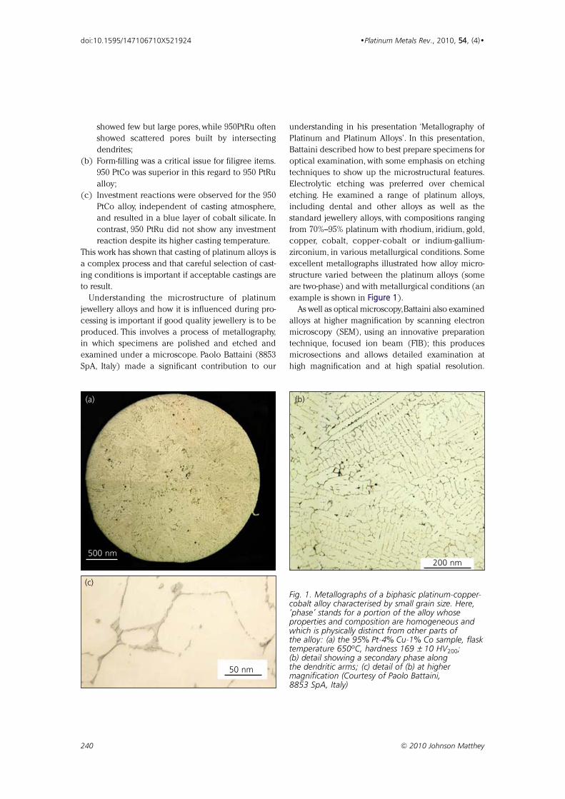
showed few but large pores, while 950PtRu often
showed scattered pores built by intersecting
dendrites;
(b) Form-filling was a critical issue for filigree items.
950 PtCo was superior in this regard to 950 PtRu
alloy;
(c) Investment reactions were observed for the 950
PtCo alloy, independent of casting atmosphere,
and resulted in a blue layer of cobalt silicate. In
contrast, 950 PtRu did not show any investment
reaction despite its higher casting temperature.
This work has shown that casting of platinum alloys is
a complex process and that careful selection of cast-
ing conditions is important if acceptable castings are
to result.
Understanding the microstructure of platinum
jewellery alloys and how it is influenced during pro-
cessing is important if good quality jewellery is to be
produced. This involves a process of metallography,
in which specimens are polished and etched and
examined under a microscope. Paolo Battaini (8853
SpA, Italy) made a significant contribution to our
understanding in his presentation ‘Metallography of
Platinum and Platinum Alloys’. In this presentation,
Battaini described how to best prepare specimens for
optical examination, with some emphasis on etching
techniques to show up the microstructural features.
Electrolytic etching was preferred over chemical
etching. He examined a range of platinum alloys,
including dental and other alloys as well as the
standard jewellery alloys, with compositions ranging
from 70%–95% platinum with rhodium, iridium, gold,
copper, cobalt, copper-cobalt or indium-gallium-
zirconium, in various metallurgical conditions. Some
excellent metallographs illustrated how alloy micro-
structure varied between the platinum alloys (some
are two-phase) and with metallurgical conditions (an
example is shown in FFiigguurree 11).
As well as optical microscopy,Battaini also examined
alloys at higher magnification by scanning electron
microscopy (SEM), using an innovative preparation
technique, focused ion beam (FIB); this produces
microsections and allows detailed examination at
high magnification and at high spatial resolution.
240 © 2010 Johnson Matthey
doi:10.1595/147106710X521924 •Platinum Metals Rev., 2010, 5544, (4)•
Fig. 1. Metallographs of a biphasic platinum-copper-cobalt alloy characterised by small grain size. Here,‘phase’ stands for a portion of the alloy whoseproperties and composition are homogeneous andwhich is physically distinct from other parts ofthe alloy: (a) the 95% Pt-4% Cu-1% Co sample, flasktemperature 650ºC, hardness 169 ± 10 HV200;(b) detail showing a secondary phase alongthe dendritic arms; (c) detail of (b) at highermagnification (Courtesy of Paolo Battaini,8853 SpA, Italy)
500 nm200 nm
(a) (b)
50 nm
(c)
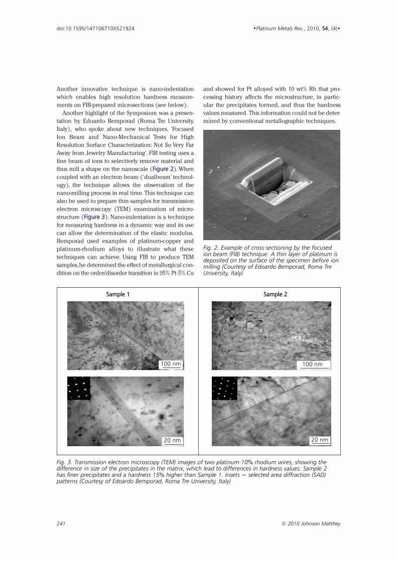
Another innovative technique is nano-indentation
which enables high resolution hardness measure-
ments on FIB-prepared microsections (see below).
Another highlight of the Symposium was a presen-
tation by Edoardo Bemporad (Roma Tre University,
Italy), who spoke about new techniques, ‘Focused
Ion Beam and Nano-Mechanical Tests for High
Resolution Surface Characterization: Not So Very Far
Away from Jewelry Manufacturing’. FIB testing uses a
fine beam of ions to selectively remove material and
thus mill a shape on the nanoscale (FFiigguurree 22). When
coupled with an electron beam (‘dualbeam’ technol-
ogy), the technique allows the observation of the
nano-milling process in real time. This technique can
also be used to prepare thin samples for transmission
electron microscopy (TEM) examination of micro-
structure (FFiigguurree 33). Nano-indentation is a technique
for measuring hardness in a dynamic way and its use
can allow the determination of the elastic modulus.
Bemporad used examples of platinum-copper and
platinum-rhodium alloys to illustrate what these
techniques can achieve. Using FIB to produce TEM
samples,he determined the effect of metallurgical con-
dition on the order/disorder transition in 95% Pt-5% Cu
and showed for Pt alloyed with 10 wt% Rh that pro-
cessing history affects the microstructure, in partic-
ular the precipitates formed, and thus the hardness
values measured. This information could not be deter-
mined by conventional metallographic techniques.
241 © 2010 Johnson Matthey
doi:10.1595/147106710X521924 •Platinum Metals Rev., 2010, 5544, (4)•
Fig. 2. Example of cross-sectioning by the focusedion beam (FIB) technique. A thin layer of platinum isdeposited on the surface of the specimen before ionmilling (Courtesy of Edoardo Bemporad, Roma TreUniversity, Italy)
SSaammppllee 11 SSaammppllee 22
100 nm 100 nm
20 nm20 nm
Fig. 3. Transmission electron microscopy (TEM) images of two platinum-10% rhodium wires, showing thedifference in size of the precipitates in the matrix, which lead to differences in hardness values. Sample 2has finer precipitates and a hardness 15% higher than Sample 1. Insets = selected area diffraction (SAD)patterns (Courtesy of Edoardo Bemporad, Roma Tre University, Italy)
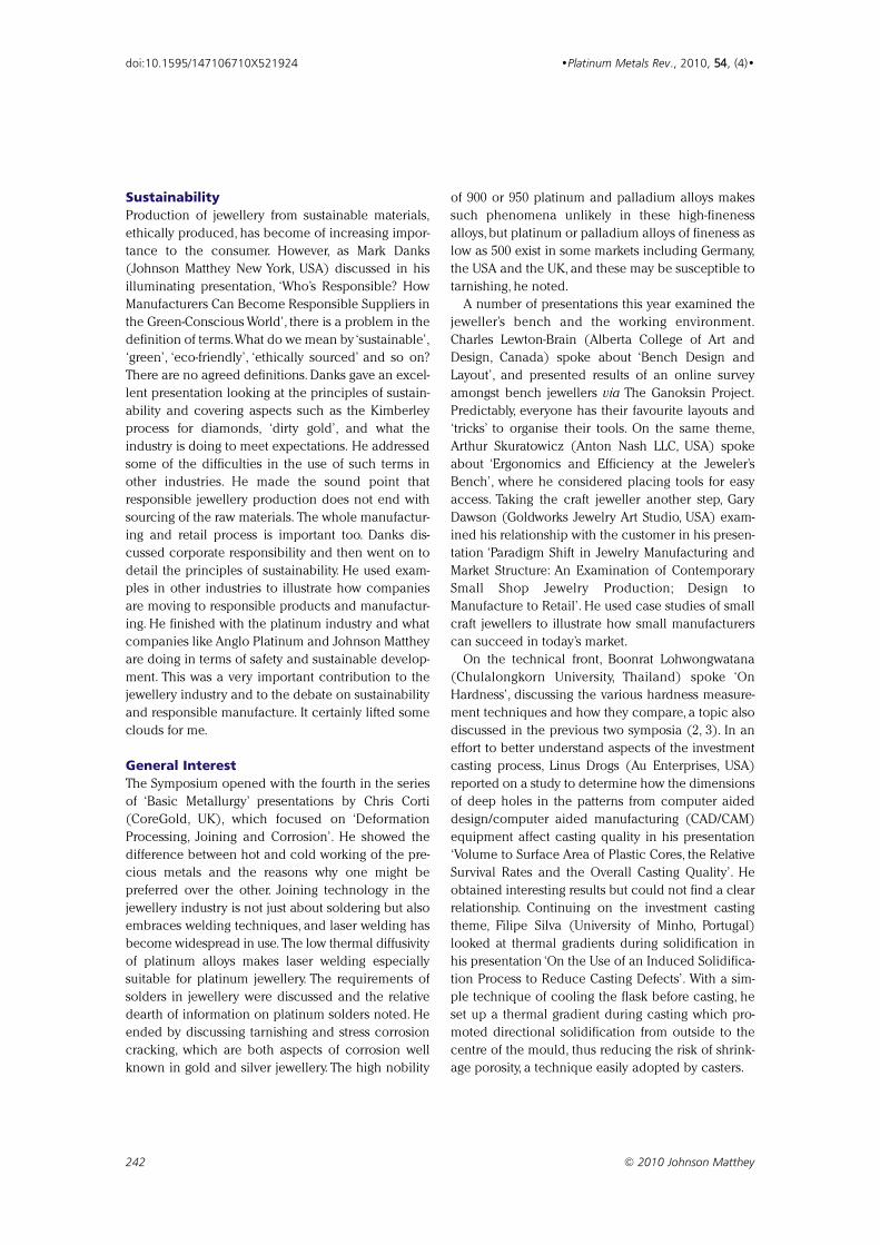
Sustainability
Production of jewellery from sustainable materials,
ethically produced, has become of increasing impor-
tance to the consumer. However, as Mark Danks
(Johnson Matthey New York, USA) discussed in his
illuminating presentation, ‘Who’s Responsible? How
Manufacturers Can Become Responsible Suppliers in
the Green-Conscious World’, there is a problem in the
definition of terms.What do we mean by ‘sustainable’,
‘green’, ‘eco-friendly’, ‘ethically sourced’ and so on?
There are no agreed definitions. Danks gave an excel-
lent presentation looking at the principles of sustain-
ability and covering aspects such as the Kimberley
process for diamonds, ‘dirty gold’, and what the
industry is doing to meet expectations. He addressed
some of the difficulties in the use of such terms in
other industries. He made the sound point that
responsible jewellery production does not end with
sourcing of the raw materials. The whole manufactur-
ing and retail process is important too. Danks dis-
cussed corporate responsibility and then went on to
detail the principles of sustainability. He used exam-
ples in other industries to illustrate how companies
are moving to responsible products and manufactur-
ing. He finished with the platinum industry and what
companies like Anglo Platinum and Johnson Matthey
are doing in terms of safety and sustainable develop-
ment. This was a very important contribution to the
jewellery industry and to the debate on sustainability
and responsible manufacture. It certainly lifted some
clouds for me.
General Interest
The Symposium opened with the fourth in the series
of ‘Basic Metallurgy’ presentations by Chris Corti
(CoreGold, UK), which focused on ‘Deformation
Processing, Joining and Corrosion’. He showed the
difference between hot and cold working of the pre-
cious metals and the reasons why one might be
preferred over the other. Joining technology in the
jewellery industry is not just about soldering but also
embraces welding techniques, and laser welding has
become widespread in use. The low thermal diffusivity
of platinum alloys makes laser welding especially
suitable for platinum jewellery. The requirements of
solders in jewellery were discussed and the relative
dearth of information on platinum solders noted. He
ended by discussing tarnishing and stress corrosion
cracking, which are both aspects of corrosion well
known in gold and silver jewellery. The high nobility
of 900 or 950 platinum and palladium alloys makes
such phenomena unlikely in these high-fineness
alloys, but platinum or palladium alloys of fineness as
low as 500 exist in some markets including Germany,
the USA and the UK, and these may be susceptible to
tarnishing, he noted.
A number of presentations this year examined the
jeweller’s bench and the working environment.
Charles Lewton-Brain (Alberta College of Art and
Design, Canada) spoke about ‘Bench Design and
Layout’, and presented results of an online survey
amongst bench jewellers via The Ganoksin Project.
Predictably, everyone has their favourite layouts and
‘tricks’ to organise their tools. On the same theme,
Arthur Skuratowicz (Anton Nash LLC, USA) spoke
about ‘Ergonomics and Efficiency at the Jeweler’s
Bench’, where he considered placing tools for easy
access. Taking the craft jeweller another step, Gary
Dawson (Goldworks Jewelry Art Studio, USA) exam-
ined his relationship with the customer in his presen-
tation ‘Paradigm Shift in Jewelry Manufacturing and
Market Structure: An Examination of Contemporary
Small Shop Jewelry Production; Design to
Manufacture to Retail’. He used case studies of small
craft jewellers to illustrate how small manufacturers
can succeed in today’s market.
On the technical front, Boonrat Lohwongwatana
(Chulalongkorn University, Thailand) spoke ‘On
Hardness’, discussing the various hardness measure-
ment techniques and how they compare, a topic also
discussed in the previous two symposia (2, 3). In an
effort to better understand aspects of the investment
casting process, Linus Drogs (Au Enterprises, USA)
reported on a study to determine how the dimensions
of deep holes in the patterns from computer aided
design/computer aided manufacturing (CAD/CAM)
equipment affect casting quality in his presentation
‘Volume to Surface Area of Plastic Cores, the Relative
Survival Rates and the Overall Casting Quality’. He
obtained interesting results but could not find a clear
relationship. Continuing on the investment casting
theme, Filipe Silva (University of Minho, Portugal)
looked at thermal gradients during solidification in
his presentation ‘On the Use of an Induced Solidifica-
tion Process to Reduce Casting Defects’. With a sim-
ple technique of cooling the flask before casting, he
set up a thermal gradient during casting which pro-
moted directional solidification from outside to the
centre of the mould, thus reducing the risk of shrink-
age porosity, a technique easily adopted by casters.
242 © 2010 Johnson Matthey
doi:10.1595/147106710X521924 •Platinum Metals Rev., 2010, 5544, (4)•
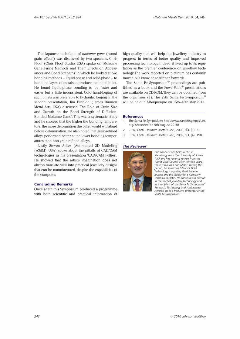
The Japanese technique of mokume gane (‘wood
grain effect’) was discussed by two speakers. Chris
Ploof (Chris Ploof Studio, USA) spoke on ‘Mokume
Gane Firing Methods and Their Effects on Appear-
ances and Bond Strengths’ in which he looked at two
bonding methods – liquid-phase and solid-phase – to
bond the layers of metals to produce the initial billet.
He found liquid-phase bonding to be faster and
easier but a little inconsistent. Cold hand-forging of
such billets was preferable to hydraulic forging. In the
second presentation, Jim Binnion (James Binnion
Metal Arts, USA) discussed ‘The Role of Grain Size
and Growth on the Bond Strength of Diffusion-
Bonded Mokume Gane’. This was a systematic study
and he showed that the higher the bonding tempera-
ture, the more deformation the billet would withstand
before delamination. He also noted that grain-refined
alloys performed better at the lower bonding temper-
atures than non-grain-refined alloys.
Lastly, Steven Adler (Automated 3D Modeling
(A3dM), USA) spoke about the pitfalls of CAD/CAM
technologies in his presentation ‘CAD/CAM Follies’.
He showed that the artist’s imagination does not
always translate well into practical jewellery designs
that can be manufactured, despite the capabilities of
the computer.
Concluding Remarks
Once again this Symposium produced a programme
with both scientific and practical information of
high quality that will help the jewellery industry to
progress in terms of better quality and improved
processing technology. Indeed, it lived up to its repu-
tation as the premier conference on jewellery tech-
nology. The work reported on platinum has certainly
moved our knowledge further forwards.
The Santa Fe Symposium® proceedings are pub-
lished as a book and the PowerPoint® presentations
are available on CD-ROM.They can be obtained from
the organisers (1). The 25th Santa Fe Symposium®
will be held in Albuquerque on 15th–18th May 2011.
References1 The Santa Fe Symposium: http://www.santafesymposium.
org/ (Accessed on 5th August 2010)
2 C. W. Corti, Platinum Metals Rev., 2009, 5533, (1), 21
3 C. W. Corti, Platinum Metals Rev., 2009, 5533, (4), 198
The Reviewer
Christopher Corti holds a PhD inMetallurgy from the University of Surrey(UK) and has recently retired from theWorld Gold Council after thirteen years,the last five as a consultant. During thisperiod, he served as Editor of GoldTechnology magazine, Gold Bulletinjournal and the Goldsmith’s CompanyTechnical Bulletin. He continues to consultin the field of jewellery technology and,as a recipient of the Santa Fe Symposium®
Research, Technology and AmbassadorAwards, he is a frequent presenter at theSanta Fe Symposium.
243 © 2010 Johnson Matthey
doi:10.1595/147106710X521924 •Platinum Metals Rev., 2010, 5544, (4)•
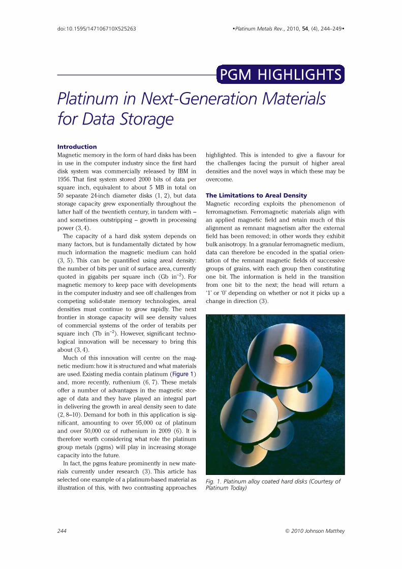
IntroductionMagnetic memory in the form of hard disks has been
in use in the computer industry since the first hard
disk system was commercially released by IBM in
1956. That first system stored 2000 bits of data per
square inch, equivalent to about 5 MB in total on
50 separate 24-inch diameter disks (1, 2), but data
storage capacity grew exponentially throughout the
latter half of the twentieth century, in tandem with –
and sometimes outstripping – growth in processing
power (3, 4).
The capacity of a hard disk system depends on
many factors, but is fundamentally dictated by how
much information the magnetic medium can hold
(3, 5). This can be quantified using areal density:
the number of bits per unit of surface area, currently
quoted in gigabits per square inch (Gb in−2). For
magnetic memory to keep pace with developments
in the computer industry and see off challenges from
competing solid-state memory technologies, areal
densities must continue to grow rapidly. The next
frontier in storage capacity will see density values
of commercial systems of the order of terabits per
square inch (Tb in−2). However, significant techno-
logical innovation will be necessary to bring this
about (3, 4).
Much of this innovation will centre on the mag-
netic medium: how it is structured and what materials
are used. Existing media contain platinum (Figure 1)
and, more recently, ruthenium (6, 7). These metals
offer a number of advantages in the magnetic stor-
age of data and they have played an integral part
in delivering the growth in areal density seen to date
(2, 8–10). Demand for both in this application is sig-
nificant, amounting to over 95,000 oz of platinum
and over 50,000 oz of ruthenium in 2009 (6). It is
therefore worth considering what role the platinum
group metals (pgms) will play in increasing storage
capacity into the future.
In fact, the pgms feature prominently in new mate-
rials currently under research (3). This article has
selected one example of a platinum-based material as
illustration of this, with two contrasting approaches
highlighted. This is intended to give a flavour for
the challenges facing the pursuit of higher areal
densities and the novel ways in which these may be
overcome.
The Limitations to Areal DensityMagnetic recording exploits the phenomenon of
ferromagnetism. Ferromagnetic materials align with
an applied magnetic field and retain much of this
alignment as remnant magnetism after the external
field has been removed; in other words they exhibit
bulk anisotropy. In a granular ferromagnetic medium,
data can therefore be encoded in the spatial orien-
tation of the remnant magnetic fields of successive
groups of grains, with each group then constituting
one bit. The information is held in the transition
from one bit to the next; the head will return a
‘1’ or ‘0’ depending on whether or not it picks up a
change in direction (3).
244 © 2010 Johnson Matthey
doi:10.1595/147106710X525263 •Platinum Metals Rev., 2010, 54, (4), 244–249•
Platinum in Next-Generation Materialsfor Data Storage
PPGGMM HHIIGGHHLLIIGGHHTTSS
Fig. 1. Platinum alloy coated hard disks (Courtesy ofPlatinum Today)
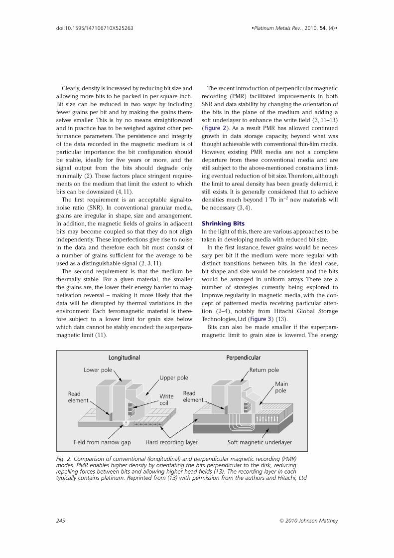
Clearly, density is increased by reducing bit size and
allowing more bits to be packed in per square inch.
Bit size can be reduced in two ways: by including
fewer grains per bit and by making the grains them-
selves smaller. This is by no means straightforward
and in practice has to be weighed against other per-
formance parameters. The persistence and integrity
of the data recorded in the magnetic medium is of
particular importance: the bit configuration should
be stable, ideally for five years or more, and the
signal output from the bits should degrade only
minimally (2). These factors place stringent require-
ments on the medium that limit the extent to which
bits can be downsized (4, 11).
The first requirement is an acceptable signal-to-
noise ratio (SNR). In conventional granular media,
grains are irregular in shape, size and arrangement.
In addition, the magnetic fields of grains in adjacent
bits may become coupled so that they do not align
independently. These imperfections give rise to noise
in the data and therefore each bit must consist of
a number of grains sufficient for the average to be
used as a distinguishable signal (2, 3, 11).
The second requirement is that the medium be
thermally stable. For a given material, the smaller
the grains are, the lower their energy barrier to mag-
netisation reversal – making it more likely that the
data will be disrupted by thermal variations in the
environment. Each ferromagnetic material is there-
fore subject to a lower limit for grain size below
which data cannot be stably encoded: the superpara-
magnetic limit (11).
The recent introduction of perpendicular magnetic
recording (PMR) facilitated improvements in both
SNR and data stability by changing the orientation of
the bits in the plane of the medium and adding a
soft underlayer to enhance the write field (3, 11–13)
(Figure 2). As a result PMR has allowed continued
growth in data storage capacity, beyond what was
thought achievable with conventional thin-film media.
However, existing PMR media are not a complete
departure from these conventional media and are
still subject to the above-mentioned constraints limit-
ing eventual reduction of bit size.Therefore, although
the limit to areal density has been greatly deferred, it
still exists. It is generally considered that to achieve
densities much beyond 1 Tb in−2 new materials will
be necessary (3, 4).
Shrinking BitsIn the light of this, there are various approaches to be
taken in developing media with reduced bit size.
In the first instance, fewer grains would be neces-
sary per bit if the medium were more regular with
distinct transitions between bits. In the ideal case,
bit shape and size would be consistent and the bits
would be arranged in uniform arrays. There are a
number of strategies currently being explored to
improve regularity in magnetic media, with the con-
cept of patterned media receiving particular atten-
tion (2–4), notably from Hitachi Global Storage
Technologies, Ltd (Figure 3) (13).
Bits can also be made smaller if the superpara-
magnetic limit to grain size is lowered. The energy
245 © 2010 Johnson Matthey
doi:10.1595/147106710X525263 •Platinum Metals Rev., 2010, 54, (4)•
Longitudinal Perpendicular
Lower pole Return pole
Readelement
Hard recording layerField from narrow gap
Upper poleMainpoleRead
elementWritecoil
Soft magnetic underlayer
Fig. 2. Comparison of conventional (longitudinal) and perpendicular magnetic recording (PMR)modes. PMR enables higher density by orientating the bits perpendicular to the disk, reducingrepelling forces between bits and allowing higher head fields (13). The recording layer in eachtypically contains platinum. Reprinted from (13) with permission from the authors and Hitachi, Ltd
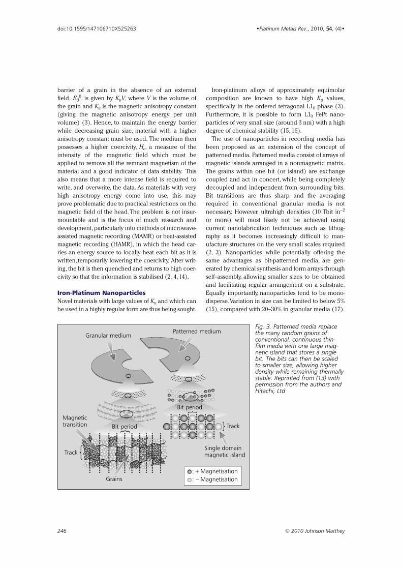
barrier of a grain in the absence of an external
field, EB0, is given by KuV, where V is the volume of
the grain and Ku is the magnetic anisotropy constant
(giving the magnetic anisotropy energy per unit
volume) (3). Hence, to maintain the energy barrier
while decreasing grain size, material with a higher
anisotropy constant must be used. The medium then
possesses a higher coercivity, Hc, a measure of the
intensity of the magnetic field which must be
applied to remove all the remnant magnetism of the
material and a good indicator of data stability. This
also means that a more intense field is required to
write, and overwrite, the data. As materials with very
high anisotropy energy come into use, this may
prove problematic due to practical restrictions on the
magnetic field of the head. The problem is not insur-
mountable and is the focus of much research and
development, particularly into methods of microwave-
assisted magnetic recording (MAMR) or heat-assisted
magnetic recording (HAMR), in which the head car-
ries an energy source to locally heat each bit as it is
written, temporarily lowering the coercivity. After writ-
ing, the bit is then quenched and returns to high coer-
civity so that the information is stabilised (2, 4, 14).
Iron-Platinum NanoparticlesNovel materials with large values of Ku and which can
be used in a highly regular form are thus being sought.
Iron-platinum alloys of approximately equimolar
composition are known to have high Ku values,
specifically in the ordered tetragonal L10 phase (3).
Furthermore, it is possible to form L10 FePt nano-
particles of very small size (around 3 nm) with a high
degree of chemical stability (15, 16).
The use of nanoparticles in recording media has
been proposed as an extension of the concept of
patterned media. Patterned media consist of arrays of
magnetic islands arranged in a nonmagnetic matrix.
The grains within one bit (or island) are exchange
coupled and act in concert, while being completely
decoupled and independent from surrounding bits.
Bit transitions are thus sharp, and the averaging
required in conventional granular media is not
necessary. However, ultrahigh densities (10 Tbit in−2
or more) will most likely not be achieved using
current nanofabrication techniques such as lithog-
raphy as it becomes increasingly difficult to man-
ufacture structures on the very small scales required
(2, 3). Nanoparticles, while potentially offering the
same advantages as bit-patterned media, are gen-
erated by chemical synthesis and form arrays through
self -assembly, allowing smaller sizes to be obtained
and facilitating regular arrangement on a substrate.
Equally importantly, nanoparticles tend to be mono-
disperse.Variation in size can be limited to below 5%
(15), compared with 20–30% in granular media (17).
246 © 2010 Johnson Matthey
doi:10.1595/147106710X525263 •Platinum Metals Rev., 2010, 54, (4)•
Granular mediumPatterned medium
Magnetictransition Bit period
Bit period
Track
Track
Grains
Single domainmagnetic island
:+Magnetisation: – Magnetisation
Fig. 3. Patterned media replacethe many random grains ofconventional, continuous thin-film media with one large mag-netic island that stores a singlebit. The bits can then be scaledto smaller size, allowing higherdensity while remaining thermallystable. Reprinted from (13) withpermission from the authors andHitachi, Ltd
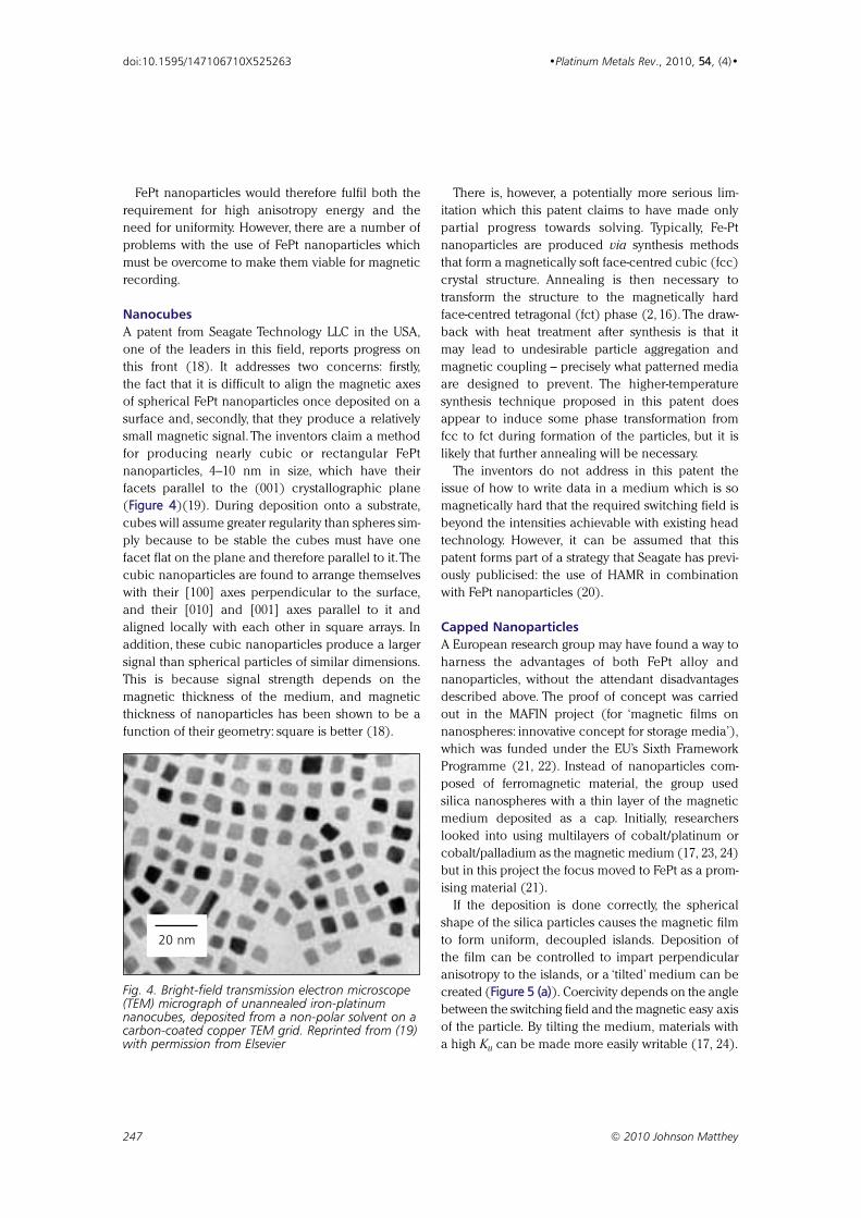
FePt nanoparticles would therefore fulfil both the
requirement for high anisotropy energy and the
need for uniformity. However, there are a number of
problems with the use of FePt nanoparticles which
must be overcome to make them viable for magnetic
recording.
NanocubesA patent from Seagate Technology LLC in the USA,
one of the leaders in this field, reports progress on
this front (18). It addresses two concerns: firstly,
the fact that it is difficult to align the magnetic axes
of spherical FePt nanoparticles once deposited on a
surface and, secondly, that they produce a relatively
small magnetic signal. The inventors claim a method
for producing nearly cubic or rectangular FePt
nanoparticles, 4–10 nm in size, which have their
facets parallel to the (001) crystallographic plane
(Figure 4)(19). During deposition onto a substrate,
cubes will assume greater regularity than spheres sim-
ply because to be stable the cubes must have one
facet flat on the plane and therefore parallel to it.The
cubic nanoparticles are found to arrange themselves
with their [100] axes perpendicular to the surface,
and their [010] and [001] axes parallel to it and
aligned locally with each other in square arrays. In
addition, these cubic nanoparticles produce a larger
signal than spherical particles of similar dimensions.
This is because signal strength depends on the
magnetic thickness of the medium, and magnetic
thickness of nanoparticles has been shown to be a
function of their geometry: square is better (18).
There is, however, a potentially more serious lim-
itation which this patent claims to have made only
partial progress towards solving. Typically, Fe-Pt
nanoparticles are produced via synthesis methods
that form a magnetically soft face-centred cubic (fcc)
crystal structure. Annealing is then necessary to
transform the structure to the magnetically hard
face-centred tetragonal (fct) phase (2, 16). The draw-
back with heat treatment after synthesis is that it
may lead to undesirable particle aggregation and
magnetic coupling – precisely what patterned media
are designed to prevent. The higher-temperature
synthesis technique proposed in this patent does
appear to induce some phase transformation from
fcc to fct during formation of the particles, but it is
likely that further annealing will be necessary.
The inventors do not address in this patent the
issue of how to write data in a medium which is so
magnetically hard that the required switching field is
beyond the intensities achievable with existing head
technology. However, it can be assumed that this
patent forms part of a strategy that Seagate has previ-
ously publicised: the use of HAMR in combination
with FePt nanoparticles (20).
Capped NanoparticlesA European research group may have found a way to
harness the advantages of both FePt alloy and
nanoparticles, without the attendant disadvantages
described above. The proof of concept was carried
out in the MAFIN project (for ‘magnetic films on
nanospheres: innovative concept for storage media’),
which was funded under the EU’s Sixth Framework
Programme (21, 22). Instead of nanoparticles com-
posed of ferromagnetic material, the group used
silica nanospheres with a thin layer of the magnetic
medium deposited as a cap. Initially, researchers
looked into using multilayers of cobalt/platinum or
cobalt/palladium as the magnetic medium (17, 23, 24)
but in this project the focus moved to FePt as a prom-
ising material (21).
If the deposition is done correctly, the spherical
shape of the silica particles causes the magnetic film
to form uniform, decoupled islands. Deposition of
the film can be controlled to impart perpendicular
anisotropy to the islands, or a ‘tilted’ medium can be
created (Figure 5 (a)). Coercivity depends on the angle
between the switching field and the magnetic easy axis
of the particle. By tilting the medium, materials with
a high Ku can be made more easily writable (17, 24).
247 © 2010 Johnson Matthey
doi:10.1595/147106710X525263 •Platinum Metals Rev., 2010, 54, (4)•
Fig. 4. Bright-field transmission electron microscope(TEM) micrograph of unannealed iron-platinumnanocubes, deposited from a non-polar solvent on acarbon-coated copper TEM grid. Reprinted from (19)with permission from Elsevier
20 nm
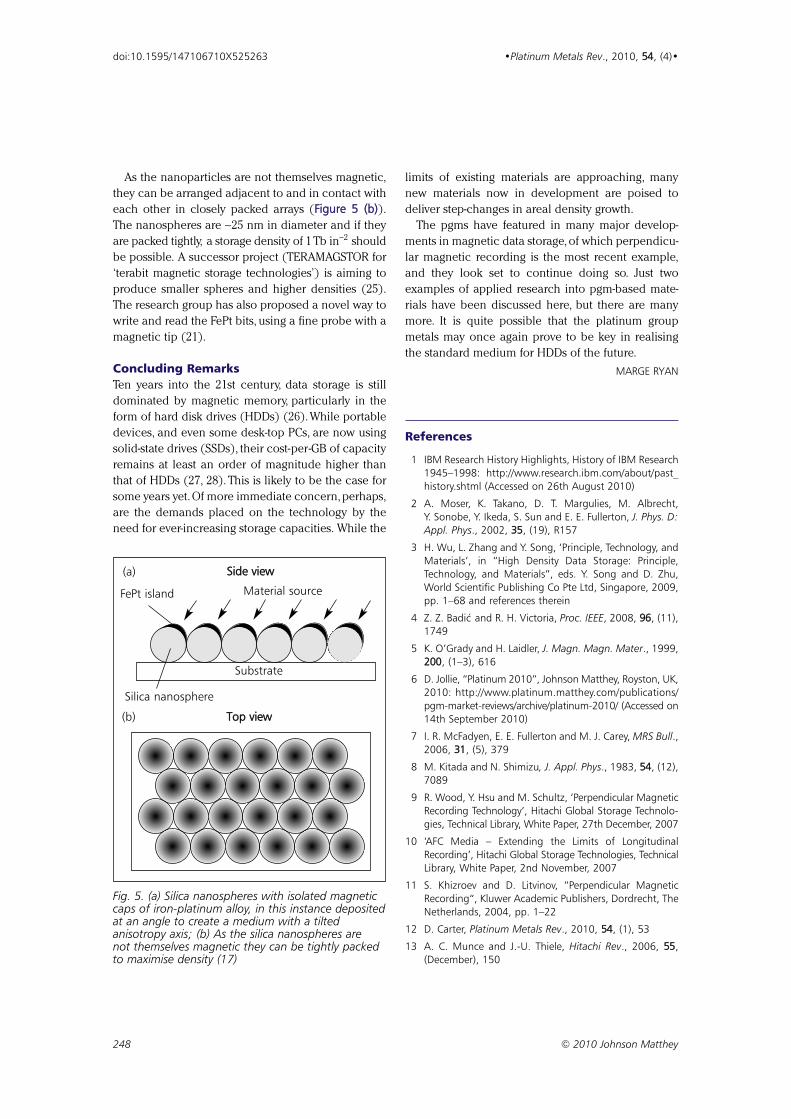
As the nanoparticles are not themselves magnetic,
they can be arranged adjacent to and in contact with
each other in closely packed arrays (Figure 5 (b)).
The nanospheres are ∼25 nm in diameter and if they
are packed tightly, a storage density of 1 Tb in−2 should
be possible. A successor project (TERAMAGSTOR for
‘terabit magnetic storage technologies’) is aiming to
produce smaller spheres and higher densities (25).
The research group has also proposed a novel way to
write and read the FePt bits, using a fine probe with a
magnetic tip (21).
Concluding RemarksTen years into the 21st century, data storage is still
dominated by magnetic memory, particularly in the
form of hard disk drives (HDDs) (26). While portable
devices, and even some desk-top PCs, are now using
solid-state drives (SSDs), their cost-per-GB of capacity
remains at least an order of magnitude higher than
that of HDDs (27, 28). This is likely to be the case for
some years yet. Of more immediate concern, perhaps,
are the demands placed on the technology by the
need for ever-increasing storage capacities. While the
limits of existing materials are approaching, many
new materials now in development are poised to
deliver step-changes in areal density growth.
The pgms have featured in many major develop-
ments in magnetic data storage, of which perpendicu-
lar magnetic recording is the most recent example,
and they look set to continue doing so. Just two
examples of applied research into pgm-based mate-
rials have been discussed here, but there are many
more. It is quite possible that the platinum group
metals may once again prove to be key in realising
the standard medium for HDDs of the future.
MARGE RYAN
References
1 IBM Research History Highlights, History of IBM Research1945–1998: http://www.research.ibm.com/about/past_history.shtml (Accessed on 26th August 2010)
2 A. Moser, K. Takano, D. T. Margulies, M. Albrecht,Y. Sonobe, Y. Ikeda, S. Sun and E. E. Fullerton, J. Phys. D:Appl. Phys., 2002, 35, (19), R157
3 H. Wu, L. Zhang and Y. Song, ‘Principle, Technology, andMaterials’, in “High Density Data Storage: Principle,Technology, and Materials”, eds. Y. Song and D. Zhu,World Scientific Publishing Co Pte Ltd, Singapore, 2009,pp. 1–68 and references therein
4 Z. Z. Badic and R. H. Victoria, Proc. IEEE, 2008, 96, (11),1749
5 K. O’Grady and H. Laidler, J. Magn. Magn. Mater., 1999,200, (1–3), 616
6 D. Jollie, “Platinum 2010”, Johnson Matthey, Royston, UK,2010: http://www.platinum.matthey.com/publications/pgm-market-reviews/archive/platinum-2010/ (Accessed on14th September 2010)
7 I. R. McFadyen, E. E. Fullerton and M. J. Carey, MRS Bull.,2006, 31, (5), 379
8 M. Kitada and N. Shimizu, J. Appl. Phys., 1983, 54, (12),7089
9 R. Wood, Y. Hsu and M. Schultz, ‘Perpendicular MagneticRecording Technology’, Hitachi Global Storage Technolo-gies, Technical Library, White Paper, 27th December, 2007
10 ‘AFC Media – Extending the Limits of LongitudinalRecording’, Hitachi Global Storage Technologies, TechnicalLibrary, White Paper, 2nd November, 2007
11 S. Khizroev and D. Litvinov, “Perpendicular MagneticRecording“, Kluwer Academic Publishers, Dordrecht, TheNetherlands, 2004, pp. 1–22
12 D. Carter, Platinum Metals Rev., 2010, 54, (1), 53
13 A. C. Munce and J.-U. Thiele, Hitachi Rev., 2006, 55,(December), 150
248 © 2010 Johnson Matthey
doi:10.1595/147106710X525263 •Platinum Metals Rev., 2010, 54, (4)•
Top view
Side view
Material source
Silica nanosphere
FePt island
Substrate
(b)
(a)
Fig. 5. (a) Silica nanospheres with isolated magneticcaps of iron-platinum alloy, in this instance depositedat an angle to create a medium with a tiltedanisotropy axis; (b) As the silica nanospheres arenot themselves magnetic they can be tightly packedto maximise density (17)
14 K. Matsumoto, A. Inomata and S. Hasegawa, Fujitsu Sci.Tech. J., 2006, 42, (1), 158
15 S. Sun, C. B. Murray, D. Weller, L. Folks and A. Moser,Science, 2000, 287, (5460), 1989
16 S. Sun, S. Anders, T. Thomson, J. E. E. Baglin, M. F. Toney,H. F. Hamann, C. B. Murray and B. D. Terris, J. Phys.Chem. B, 2003, 107, (23), 5419
17 G. Schatz, M. Albrecht, J. Boneberg and I. Guhr,‘Information Storage Media’, US Appl. 2008/0,171,233
18 N. Shukla, T. J. Klemmer, D. K. Weller and C. Liu, SeagateTechnology LLC, ‘Method of Producing Self-AssembledCubic FePt Nanoparticles and Apparatus Using Same’,US Appl. 2010/0,080,895
19 N. Shukla, C. Liu and A. G. Roy, Mater. Lett., 2006, 60,(8), 995
20 ‘Seagate Swings “HAMR” to Increase Disc DriveDensities by a Factor of 100’, Seagate, About Seagate,News, Press Releases, 21st August, 2002: http://www.seagate.com/ (Accessed on 26th August 2010)
21 ‘EU scientists aim to break storage capacity barrier’, CORDISNews Release, 7th July, 2010: http://cordis.europa.eu/
fetch?CALLER=EN_NEWS&ACTION=D&SESSION=&RCN=32298 (Accessed on 14th September 2010)
22 MAFIN Project: http://www.mafin-project.de/ (Accessedon 26th August 2010)
23 M. Albrecht, G. Hu, I. L. Guhr, T. C. Ulbrich, J. Boneberg,P. Leiderer and G. Schatz, Nature Mater., 2005, 4, (3), 203
24 G. Schatz, Acta Phys. Polonica A, 2009, 115, (2), 431
25 Terabit Magnetic Storage Technologies: http://www.teramagstor.eu/ (Accessed on 14th September 2010)
26 E. Pinheiro, W.-D. Weber and L. A. Barroso, ‘FailureTrends in a Large Disk Drive Population’, 5th USENIXConference on File and Storage Technologies (FAST ’07),San José, California, USA, 13th–16th February, 2007
27 J. Handy, ‘Flash Memory vs. Hard Disk Drives – WhichWill Win?’, StorageSearch.com, June, 2005: http://www.storagesearch.com/semico-art1.html (Accessed on 26thAugust 2010)
28 L. Mearian, ‘Review: Hard Disk vs. Solid-State Drive – isan SSD Worth the Money?’, Computerworld, 18th June,2009: http://www.computerworld.com/s/article/9134468/(Accessed on 26th August 2010)
249 © 2010 Johnson Matthey
doi:10.1595/147106710X525263 •Platinum Metals Rev., 2010, 54, (4)•
By George B. Kauffman*
DDeeppaarrttmmeenntt ooff CChheemmiissttrryy,, CCaalliiffoorrnniiaa SSttaattee UUnniivveerrssiittyy,,
FFrreessnnoo,, CCaalliiffoorrnniiaa 9933774400--88003344,, UUSSAA;;
**EE--mmaaiill:: ggeeoorrggeekk@@ccssuuffrreessnnoo..eedduu
Raffaele Pentimalli
UUnniivveerrssiittàà ddeellllaa VVaallllee dd’’AAoossttaa,, SSttrraaddaa ddeeii CCaappppuucccciinnii 22AA,,
1111110000 AAoossttaa,, IIttaallyy;;
EE--mmaaiill:: rraaffffaaeellee..ppeennttiimmaallllii@@vviirrggiilliioo..iitt
Sandro Doldi (1908–2001)
and Matthew D. Hall
NNaattiioonnaall CCaanncceerr IInnssttiittuuttee,, NNaattiioonnaall IInnssttiittuutteess ooff HHeeaalltthh,,
3377 CCoonnvveenntt DDrriivvee,, BBeetthheessddaa,, MMaarryyllaanndd 2200889922--44225588,, UUSSAA;;
EE--mmaaiill:: hhaallllmmaa@@mmaaiill..nniihh..ggoovv
The Italian chemist Michele Peyrone (1813–1883) was
the first to synthesise cisplatin (cis-diamminedichloro-
platinum (II)), the basis of today’s most widely used
family of anticancer drugs. This biographical article
aims to present, for the first time in the English lan-
guage,a summary of his life and the achievements that
he made during his scientific career.Originally trained
in medicine, Peyrone moved to chemistry and attended
some of the most prestigious institutions in Europe in
his time. He wrote several publications describing his
work on ‘Peyrone’s chloride’ (PtCl2(NH3 )2 ) and
Magnus’ green salt ([Pt(NH3 )4 ][PtCl4]). He later
turned his attention to agricultural science where he
defended important advances in the understanding of
plant growth. Michele Peyrone’s dedication to science
is best summarised in the English translation of his
first report on the synthesis of cisplatin: “I am deter-
mined to pursue this subject with all my energies,with-
out having regard for the difficulties to be encountered
at every step in so expensive and delicate a research”.
In this age of high-throughput drug discovery, medici-
nal chemistry and targeted therapies, there are few
clinically used anticancer drugs that were syn-
thesised 130 years before their biological activity was
discovered. An alert reader will immediately think
of the arsenal of natural products that have found
application in the clinic in recent years, but even
these have been semi-synthetically modified follow-
ing their discoveries. By contrast, one of the
most widely used anticancer drugs today, cis-
diamminedichloroplatinum (II) or cisplatin, originally
known as Peyrone’s chloride, was first prepared in its
presently used form by Italian chemist Michele
Peyrone in 1844 (1). It later played a central role in
the Nobel prize-winning work of Swiss chemist Alfred
Werner (1866–1919) (2, 3) on isomerism in inorganic
complexes. The cytostatic activity of cisplatin was first
reported by Barnett (Barney) Rosenberg (1926–2009)
and coworkers in 1965 (4), and it progressed rapidly
into the clinic (5). Many publications concerning
250 © 2010 Johnson Matthey
•Platinum Metals Rev., 2010, 5544, (4), 250–256•
Michele Peyrone (1813–1883),Discoverer of Cisplatin
doi:10.1595/147106710X534326 http://www.platinummetalsreview.com/
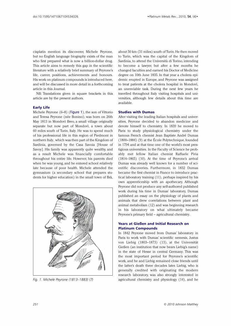
cisplatin mention its discoverer, Michele Peyrone,
but no English language biography exists of the man
who first prepared what is now a billion-dollar drug.
This article aims to remedy this gap in the scientific
literature with a relatively brief summary of Peyrone’s
life, career, positions, achievements and honours.
His work on platinum compounds is introduced here,
and will be discussed in more detail in a forthcoming
article in this Journal.
NB: Translations given in square brackets in this
article are by the present authors.
Early Life
Michele Peyrone (6–8) (FFiigguurree 11), the son of Vittorio
and Teresa Peyrone (née Bonino), was born on 26th
May 1813 in Mondovì Breo, a small village originally
separate but now part of Mondovì, a town about
60 miles south of Turin, Italy. He was to spend much
of his professional life in this region of Piedmont in
northern Italy, which was then part of the Kingdom of
Sardinia, governed by the Casa Savoia [House of
Savoy]. His family was apparently quite wealthy, and
as a result Michele was financially comfortable
throughout his entire life. However, his parents died
when he was young, and he entered school relatively
late because of poor health. Michele attended the
gymnasium (a secondary school that prepares stu-
dents for higher education) in the small town of Brà,
about 50 km (31 miles) south of Turin. He then moved
to Turin, which was the capital of the Kingdom of
Sardinia, to attend the Università di Torino, intending
to become a lawyer, but after a few months he
changed faculties and earned his Doctor of Medicine
degree on 10th June 1835. In that year a cholera epi-
demic erupted in Europe, and Peyrone was assigned
to treat patients at the cholera hospital in Mondovì,
an unenviable task. During the next few years he
travelled throughout Italy visiting hospitals and uni-
versities, although few details about this time are
available.
Studies with Dumas
After visiting the leading Italian hospitals and univer-
sities, Peyrone decided to abandon medicine and
devote himself to chemistry. In 1839 he moved to
Paris to study physiological chemistry under the
famous French chemist Jean Baptiste André Dumas
(1800–1884) (9) at the École Polytechnique, founded
in 1794 and at that time one of the world’s most pres-
tigious universities. In the Faculty of Science he prob-
ably met fellow Italian chemist Raffaele Piria
(1814–1865) (10). At the time of Peyrone’s arrival
Dumas was already well known for a number of sci-
entific discoveries. Furthermore, in 1832 Dumas
became the first chemist in France to introduce prac-
tical laboratory training (11), perhaps inspired by his
own apprenticeship with an apothecary. Although
Peyrone did not produce any self-authored published
work during his time in Dumas’ laboratory, Dumas
published an essay on the physiology of plants and
animals that drew correlations between plant and
animal metabolism (12) and was beginning research
in his laboratory on what ultimately became
Peyrone’s primary field – agricultural chemistry.
Years at Gießen and Initial Research on
Platinum Compounds
In 1842 Peyrone moved from Dumas’ laboratory in
Paris to work with Dumas’ scientific nemesis, Justus
von Liebig (1803–1873) (13), at the Universität
Gießen (an institution that now bears Liebig’s name)
in the state of Hesse in central Germany. This was
the most important period for Peyrone’s scientific
work, and he and Liebig remained close friends until
the latter’s death three decades later. Liebig, who is
generally credited with originating the modern
research laboratory, was also strongly interested in
agricultural chemistry and physiology (14), and he
251 © 2010 Johnson Matthey
doi:10.1595/147106710X534326 •Platinum Metals Rev., 2010, 5544, (4)•
Fig. 1. Michele Peyrone (1813–1883) (7)
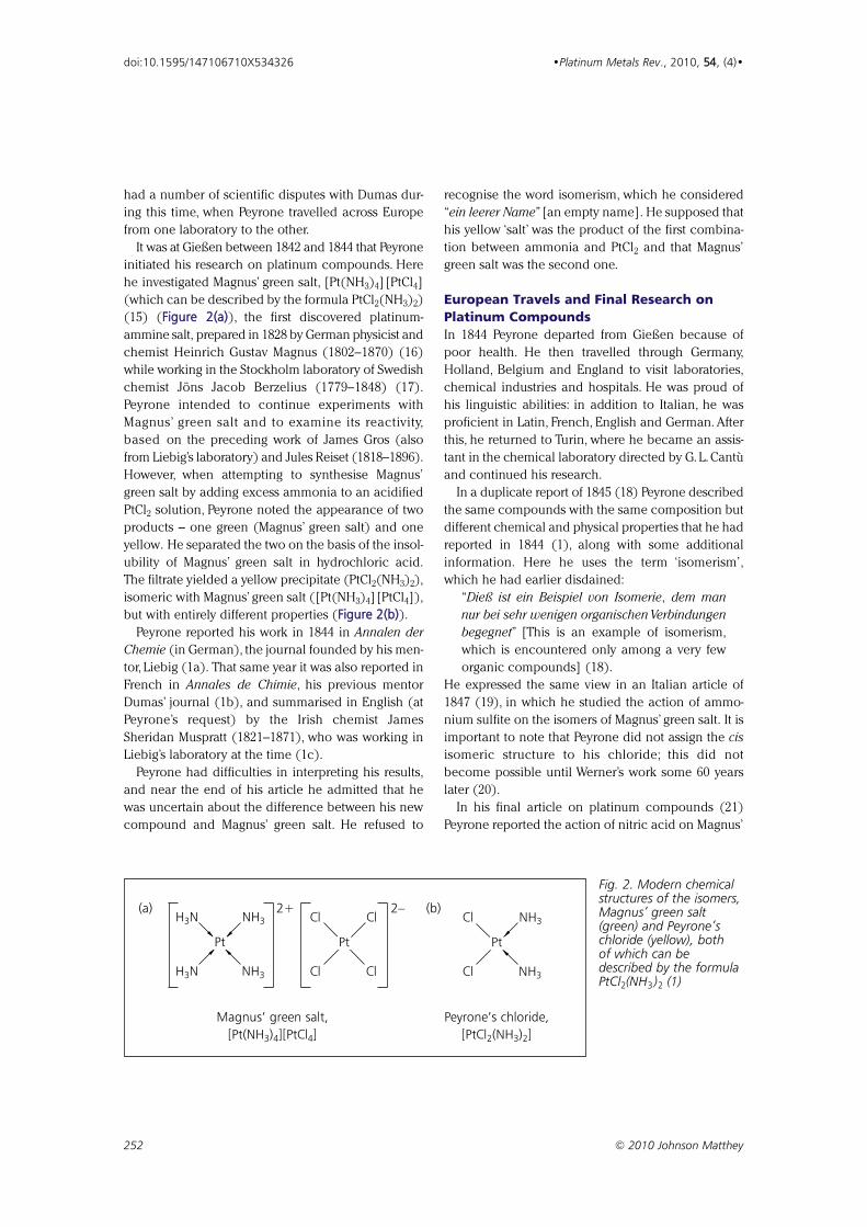
had a number of scientific disputes with Dumas dur-
ing this time, when Peyrone travelled across Europe
from one laboratory to the other.
It was at Gießen between 1842 and 1844 that Peyrone
initiated his research on platinum compounds. Here
he investigated Magnus’ green salt, [Pt(NH3)4][PtCl4]
(which can be described by the formula PtCl2(NH3)2)
(15) (FFiigguurree 22((aa))), the first discovered platinum-
ammine salt, prepared in 1828 by German physicist and
chemist Heinrich Gustav Magnus (1802–1870) (16)
while working in the Stockholm laboratory of Swedish
chemist Jöns Jacob Berzelius (1779–1848) (17).
Peyrone intended to continue experiments with
Magnus’ green salt and to examine its reactivity,
based on the preceding work of James Gros (also
from Liebig’s laboratory) and Jules Reiset (1818–1896).
However, when attempting to synthesise Magnus’
green salt by adding excess ammonia to an acidified
PtCl2 solution, Peyrone noted the appearance of two
products – one green (Magnus’ green salt) and one
yellow. He separated the two on the basis of the insol-
ubility of Magnus’ green salt in hydrochloric acid.
The filtrate yielded a yellow precipitate (PtCl2(NH3)2),
isomeric with Magnus’ green salt ([Pt(NH3)4][PtCl4]),
but with entirely different properties (FFiigguurree 22((bb))).
Peyrone reported his work in 1844 in Annalen der
Chemie (in German), the journal founded by his men-
tor, Liebig (1a). That same year it was also reported in
French in Annales de Chimie, his previous mentor
Dumas’ journal (1b), and summarised in English (at
Peyrone’s request) by the Irish chemist James
Sheridan Muspratt (1821–1871), who was working in
Liebig’s laboratory at the time (1c).
Peyrone had difficulties in interpreting his results,
and near the end of his article he admitted that he
was uncertain about the difference between his new
compound and Magnus’ green salt. He refused to
recognise the word isomerism, which he considered
“ein leerer Name”[an empty name]. He supposed that
his yellow ‘salt’ was the product of the first combina-
tion between ammonia and PtCl2 and that Magnus’
green salt was the second one.
European Travels and Final Research on
Platinum Compounds
In 1844 Peyrone departed from Gießen because of
poor health. He then travelled through Germany,
Holland, Belgium and England to visit laboratories,
chemical industries and hospitals. He was proud of
his linguistic abilities: in addition to Italian, he was
proficient in Latin, French, English and German. After
this, he returned to Turin, where he became an assis-
tant in the chemical laboratory directed by G. L. Cantù
and continued his research.
In a duplicate report of 1845 (18) Peyrone described
the same compounds with the same composition but
different chemical and physical properties that he had
reported in 1844 (1), along with some additional
information. Here he uses the term ‘isomerism’,
which he had earlier disdained:
“Dieß ist ein Beispiel von Isomerie, dem man
nur bei sehr wenigen organischen Verbindungen
begegnet” [This is an example of isomerism,
which is encountered only among a very few
organic compounds] (18).
He expressed the same view in an Italian article of
1847 (19), in which he studied the action of ammo-
nium sulfite on the isomers of Magnus’ green salt. It is
important to note that Peyrone did not assign the cis
isomeric structure to his chloride; this did not
become possible until Werner’s work some 60 years
later (20).
In his final article on platinum compounds (21)
Peyrone reported the action of nitric acid on Magnus’
252 © 2010 Johnson Matthey
doi:10.1595/147106710X534326 •Platinum Metals Rev., 2010, 5544, (4)•
Fig. 2. Modern chemicalstructures of the isomers,Magnus’ green salt(green) and Peyrone’schloride (yellow), bothof which can bedescribed by the formulaPtCl2(NH3 )2 (1)
H3N
H3N
NH3
NH3
2+ 2–
Magnus’ green salt,
[Pt(NH3)4][PtCl4]
Peyrone’s chloride,
[PtCl2(NH3)2]
(a) (b)
Pt
Cl
Cl
Cl
Cl
Pt
Cl
Cl
NH3
NH3
Pt
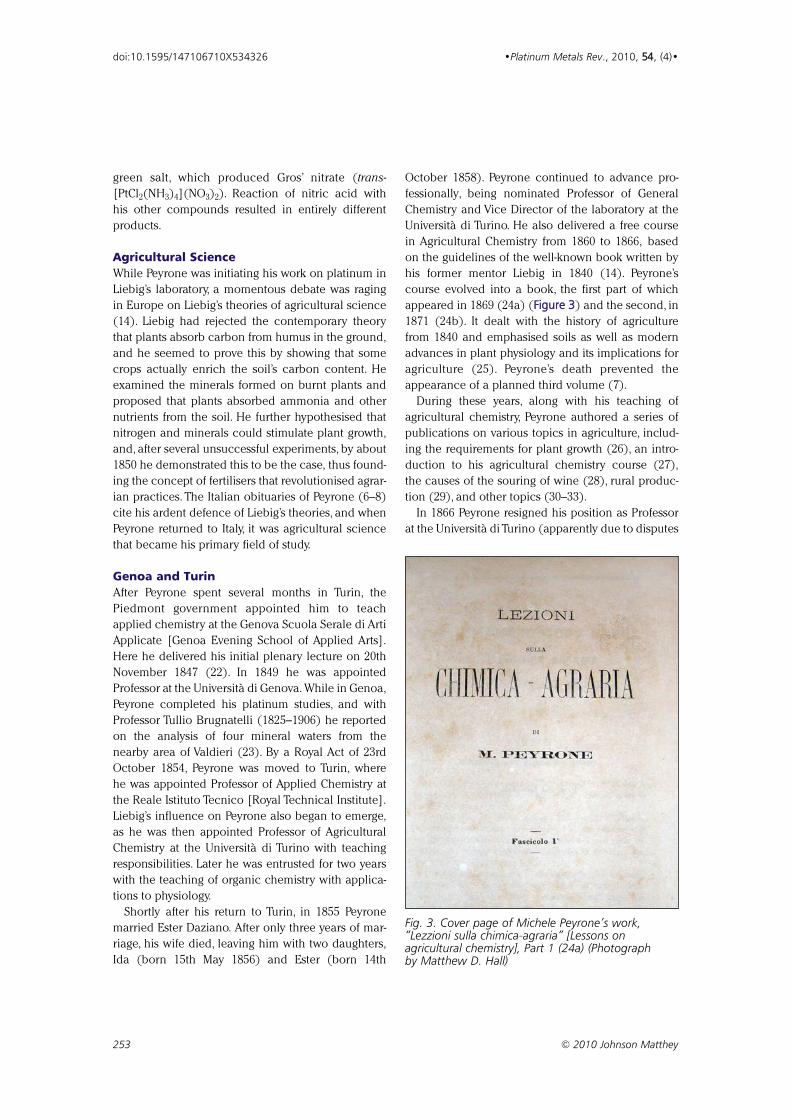
green salt, which produced Gros’ nitrate (trans-
[PtCl2(NH3)4](NO3)2). Reaction of nitric acid with
his other compounds resulted in entirely different
products.
Agricultural Science
While Peyrone was initiating his work on platinum in
Liebig’s laboratory, a momentous debate was raging
in Europe on Liebig’s theories of agricultural science
(14). Liebig had rejected the contemporary theory
that plants absorb carbon from humus in the ground,
and he seemed to prove this by showing that some
crops actually enrich the soil’s carbon content. He
examined the minerals formed on burnt plants and
proposed that plants absorbed ammonia and other
nutrients from the soil. He further hypothesised that
nitrogen and minerals could stimulate plant growth,
and, after several unsuccessful experiments, by about
1850 he demonstrated this to be the case, thus found-
ing the concept of fertilisers that revolutionised agrar-
ian practices. The Italian obituaries of Peyrone (6–8)
cite his ardent defence of Liebig’s theories, and when
Peyrone returned to Italy, it was agricultural science
that became his primary field of study.
Genoa and Turin
After Peyrone spent several months in Turin, the
Piedmont government appointed him to teach
applied chemistry at the Genova Scuola Serale di Arti
Applicate [Genoa Evening School of Applied Arts].
Here he delivered his initial plenary lecture on 20th
November 1847 (22). In 1849 he was appointed
Professor at the Università di Genova. While in Genoa,
Peyrone completed his platinum studies, and with
Professor Tullio Brugnatelli (1825–1906) he reported
on the analysis of four mineral waters from the
nearby area of Valdieri (23). By a Royal Act of 23rd
October 1854, Peyrone was moved to Turin, where
he was appointed Professor of Applied Chemistry at
the Reale Istituto Tecnico [Royal Technical Institute].
Liebig’s influence on Peyrone also began to emerge,
as he was then appointed Professor of Agricultural
Chemistry at the Università di Turino with teaching
responsibilities. Later he was entrusted for two years
with the teaching of organic chemistry with applica-
tions to physiology.
Shortly after his return to Turin, in 1855 Peyrone
married Ester Daziano. After only three years of mar-
riage, his wife died, leaving him with two daughters,
Ida (born 15th May 1856) and Ester (born 14th
October 1858). Peyrone continued to advance pro-
fessionally, being nominated Professor of General
Chemistry and Vice Director of the laboratory at the
Università di Turino. He also delivered a free course
in Agricultural Chemistry from 1860 to 1866, based
on the guidelines of the well-known book written by
his former mentor Liebig in 1840 (14). Peyrone’s
course evolved into a book, the first part of which
appeared in 1869 (24a) (FFiigguurree 33) and the second, in
1871 (24b). It dealt with the history of agriculture
from 1840 and emphasised soils as well as modern
advances in plant physiology and its implications for
agriculture (25). Peyrone’s death prevented the
appearance of a planned third volume (7).
During these years, along with his teaching of
agricultural chemistry, Peyrone authored a series of
publications on various topics in agriculture, includ-
ing the requirements for plant growth (26), an intro-
duction to his agricultural chemistry course (27),
the causes of the souring of wine (28), rural produc-
tion (29), and other topics (30–33).
In 1866 Peyrone resigned his position as Professor
at the Università di Turino (apparently due to disputes
253 © 2010 Johnson Matthey
doi:10.1595/147106710X534326 •Platinum Metals Rev., 2010, 5544, (4)•
Fig. 3. Cover page of Michele Peyrone’s work,“Lezzioni sulla chimica-agraria” [Lessons onagricultural chemistry], Part 1 (24a) (Photographby Matthew D. Hall)
over the politics of promotion) and returned to
teaching at the Reale Istituto Tecnico in Turin, which
in the meantime had merged with the Reale Museo
Industriale [Royal Museum of Industry], also in Turin,
an institution founded in 1862 to promote industrial
education and the advancement of industry and
commerce and of which Peyrone was Chairman.
However, in 1867 the two institutions were divided
again, and although Peyrone requested that he be
attached to the Museo, he was instead assigned to the
Istituto Tecnico, which was not a university.
Positions and Miscellaneous Honours
From 1856 to his retirement Peyrone was appointed
a member of the Reale Accademia di Agricoltura
[Royal Academy of Agriculture] in Turin, of the
Accademia Medico-Chirurgica [Academy of Medicine
and Surgery] in Genoa, of the Società Economico-
Agraria [Society of Agrarian Economics] in Perugia,
of the Società Farmaceutica [Pharmaceutical Society]
of Sardinia, and of the Comizio Agrario [Chamber of
Agricultural Rally] in Mondovì,his birthplace. He was
named Cavaliere dell’Ordine Mauriziano [Knight of
the Order of St. Maurice] and Commendatore della
Corona d’Italia [Knight Commander of the Crown
of Italy]. During the Crimean War (1854–1856) he
was appointed Superintendent for Food of the
Piedmontese Army, and as a chemist he was
appointed by the recently unified Italy’s first Prime
Minister, Count Camillo Benso di Cavour (1810–
1861), to a committee established to study agricul-
tural problems and the use of artificial fertilisers.
Final Years
As time went on Peyrone become worn out and
fatigued. Even during his childhood he had been
unwell, and he apparently had never recovered from
the loss of his wife in about 1858 and the
premature death of his daughter Ester at the age of 13
(probably in about 1870). In 1879 he was placed on
leave for health reasons, and he ultimately retired that
same year. He moved to the small town of Magliano
Alpi close to Mondovì and then to nearby Carrù,
where his daughter Ida had married the mayor,
G. B. Reyneri. In retirement Peyrone apparently
devoted himself exclusively to the care of his ‘estates’
and to the quiet country life. He died at Carrù with
his family at his side in July 1883, at the age of 70.
Details regarding his funeral, burial or grave have not
been found.
Concluding Remarks
Obituaries of Peyrone (6–8) testify to the important
contributions that he had made to chemistry.
Although he was well known for his work on agricul-
tural chemistry, his early work on platinum was also
mentioned, demonstrating that the importance of
this work was well recognised. Vincenzo Fino
described him as “independent, of a frank and
severe character” – perhaps the qualities needed to
travel throughout Europe, succeed in the relatively
solitary pursuit of research, and defend Liebig’s prin-
ciples of agricultural science in Italy (6). Peyrone
apparently recognised his responsibility as a man
born into wealth and often stated, “the duty of the
rich is to help the poor”(6).
Perhaps Michele Peyrone’s dedication to science is
best summarised by quoting from the English transla-
tion of his first report on the synthesis of cisplatin (1c):
“I am determined to pursue this subject with all
my energies, without having regard for the diffi-
culties to be encountered at every step in so
expensive and delicate a research”.
We will examine Peyrone’s work on platinum com-
pounds in detail in a forthcoming article in Platinum
Metals Review.
Acknowledgements
This research was partly supported by the Intramural
Research Program of the National Cancer Institute,
National Institutes of Health, Bethesda, Maryland, USA.
References and Notes1 (a) M. Peyrone, ‘Ueber die Einwirkung des Ammoniaks
auf Platinchlorür’ [On the Influence of Ammonia on
Platinum Chloride], Ann. Chem. Pharm., 1844, 5511, 1;
(b) translated into French as: ‘De l’action de
l’ammoniaque sur le protochlorure de platine’, Ann.
Chim. Phys., Sér. 3, 1844, 1122, 193; and summarised in
Ann. Chim., 1845, 11, 166; (c) translated into English
by Dr Sheridan Muspratt as: ‘Action of Ammonia
upon the Protochloride of Platinum’, Med. Times, 1844,
1100, 381
2 G. B. Kauffman, “Alfred Werner: Founder of Coordination
Chemistry”, Springer-Verlag, Berlin/Heidelberg/New York,
1966
3 (a) A. Werner, ‘Beitrag zur Konstitution anorganischer
Verbindungen’, Z. Anorg. Chem., 1893, 33, 267; (b) trans-
lated into English as: ‘Contribution to the Constitution of
Inorganic Compounds’, in G. B. Kauffman, “Classics in
Coordination Chemistry, Part I: The Selected Papers of
Alfred Werner”, Classics of Science, Volume 4, Dover
Publications, New York, NY, 1968, pp. 5–88
254 © 2010 Johnson Matthey
doi:10.1595/147106710X534326 •Platinum Metals Rev., 2010, 5544, (4)•
4 B. Rosenberg, L. Van Camp and T. Krigas, Nature, 1965,
220055, (4972), 698
5 R. A. Alderden, M. D. Hall and T. W. Hambley, J. Chem.
Educ., 2006, 8833, (5), 728
6 V. Fino, ‘Commemorazione del Prof. Michele Peyrone’,
Annali della Reale Accademia d’Agricoltura di Torino,
1884, 2277, 23
7 A. Strucchi, ‘Michele Peyrone’, Giornale di agricoltura,
industria e commercio del regno d’Italia, 1885, 2222, 263
8 (a) S. Doldi, ‘Michele Peyrone e il suo sale’, La Chimica e
l’Industria, 1995, 7777, (11), 989; (b) also in A. Strucchi,
“Biografie di insigni agronomi piemontesi” [Biographies
of famous agronomists of Piedmont], Casanova, Turin,
1885, p. 43
9 M. Chaigneau, “Jean-Baptiste Dumas: Sa vie, son oeuvre,
1800–1884”, Guy Le Prat, Paris, 1984
10 (a) D. Marotta, “Raffaele Piria: lavori scientifici e scritti
vari”, Tipografia Editrice Italia, Rome, 1932; (b) A. Focà
and F. Cardone, “Raffaele Piria: Medico, Chimico,
Patriota, Innovatore della Chimica in Italia”, Laruffa,
Reggio Calabria, Italy, 2003
11 L. J. Klosterman, Ann. Sci., 1985, 4422, (1), 1
12 J. B. Dumas and J. B. Boussingault, “Essai de statique
chimique des êtres organisés”, 3rd Edn., Fortin, Masson,
et Cie., Paris, 1844
13 W. H. Brock, “Justus von Liebig: The Chemical Gatekeeper”,
Cambridge University Press, Cambridge, 1997
14 (a) J. von Liebig, “Die Organische Chemie in ihrer Anwen-
dung auf Agricultur und Physiologie”, F. Vieweg,
Braunschweig, Germany, 1840; (b) “Organic Chemistry
in Its Applications to Agriculture and Physiology”, edited
and translated from the manuscript of the author by
Lyon Playfair, Taylor and Walton, London, 1840
15 G. B. Kauffman, Platinum Metals Rev., 1976, 2200, (1), 21
16 (a) G. Magnus, ‘Ueber einige Verbindungen des Plat-
inchlorürs’, Poggendorff’s Ann. Phys. Chem., 1828, 8800,
239; (b) translated into English as: ‘Some Compounds of
Platinous Chloride’, in G. B. Kauffman, “Classics in
Coordination Chemistry, Part 2: Selected Papers (1798–
1899)”, Classics of Science, Volume 7, Dover Publications,
New York, NY, 1976, pp. 7–20
17 J. E. Jorpes, “Jac. Berzelius: His Life and Work”, translated
from the Swedish by B. Steele, Almqvist & Wiksell,
Stockholm, Sweden, 1966
18 (a) M. Peyrone, ‘Ueber die Einwirkung von Ammoniak
auf Platinchlorür: Zweite Abhandlung’, Ann. Chem.
Pharm., 1845, 5555, 205; (b) translated into French as: ‘De
l’action de l’ammoniaque sur le protochlorure de platine’,
Ann. Chim. Phys., Sér. 3, 1846, 1166, 462
19 (a) M. Peyrone, ‘Ricerche comparative sopra alcuni isomeri
del sal verde di Magnus’ [Comparative researches upon
some isomers of Magnus’ green salt], Atti della Reale
Accademia delle scienze di Torino, 1847, 1100, (2), 171;
(b) translated into German as: ‘Ueber einige dem grünen
Magnus’schen Salze isomere Körper’, Ann. Chem., 1847,
6611, 178
20 G. B. Kauffman, Platinum Metals Rev., 1997, 4411, (1), 34
21 M. Peyrone, ‘Dell’azione dell’acido nitrico sopra il sal verde
di Magnus’ [Of the action of nitric acid on Magnus’
green salt], Il Nuovo Cimento, 1856, Tomo II, 387
22 (a) M. Peyrone, ‘Discorso per l’apertura delle Scuole di
Chimica e Mecanica Applicate alle Arti in Genoa’
[Speech for the opening of the Schools of Chemistry and
Mechanics Applied to the Arts in Genoa], Antologia
Italiana, Giornale di Scienze, Lettere ed Arti, 1848,
Anno II, Tomo IV, 437; (b) See also S. Doldi, ‘Le prime
scuole tecniche genovesi’ [The first technical schools in
Genoa], La Berio Servizio Biblioteche del Comune di
Genova, 1996, XXXXXXVVII, (2), 3
23 M. Peyrone, ‘Analisi di quattro acque minerali di Valdieri
fatte in unione al Professore Brugnatelli’ [Analyses of
four mineral waters of Valdieri carried out with Professor
Brugnatelli], in “Valdieri e le sue acque”, ed. G. Garelli,
Tipografia Scolastica, Turin, Italy, 1855, p. 48
24 M. Peyrone, (a) “Lezioni sulla chimica-agraria” [Lessons
on agricultural chemistry], C. Favale, Part 1, 1869, Turin,
Italy; (b) F. Bocca, Part 2, 1871, Turin, Italy
25 F. Sestini, ‘Chimica Agraria’, Annuario scientifico ed
industriale, 1870, 66, 317
26 M. Peyrone, ‘Dei bisogni della vegetazione dedotti dalle
leggi di natura’ [Of the needs of vegetation deduced
from the laws of nature], Annali della Reale Accademia
d’Agricoltura di Torino, 1857, 1100, 53; read at the
meeting of the Reale Accademia d’Agricoltura di Torino
on 14th May, 1857
27 M. Peyrone, ‘Prelazione al Corso di chimica agraria che si
dette in Torino nell’anno scolastico 1862–1863’
[Preemption to the Agricultural Chemistry course given
in Turin in the scholastic year 1862–1863], Economia
rurale, 1862, 620
28 M. Peyrone, ‘Sul vino incerconito – Notizia letta alla
Reale Accademia d’Agricoltura nella adunanza del 26
marzo 1863’ [On turbid wine – Notice read to the Reale
Accademia d’Agricoltura in the meeting of 26th March,
1863], Economia rurale, 1863, 188
29 M. Peyrone, “La produzione rurale presunta e i mezzi di
realizzarla” [Supposed rural production and the means
of achieving it], brochure published by Paravia, Turin,
Italy, 1865
30 M. Peyrone, ‘Guano Fino’ [Refined guano], Economia
rurale, 1866, 483
31 M. Peyrone, ‘La silice solubile e la potassa nei loro
rapporti colle piante’ [Soluble silica and potash and the
effect of silica and potash on plant growth], Economia
rurale, 1867, 49
32 (a) M. Peyrone, ‘Arature profonde’ [Deep ploughing].
Economia rurale, 1870, 613; (b) Rivista di Agricoltura,
Industria e Commercio di Firenze, 1870; (c) Annuario
Scientifico ed Industriale, 1870, 66, 360
33 M. Peyrone, ‘Rapporto sull’industria dello zucchero di
barbabietole’ [Report on the sugar beet industry],
Inchiesta industriale, 1872
255 © 2010 Johnson Matthey
doi:10.1595/147106710X534326 •Platinum Metals Rev., 2010, 5544, (4)•
George B. Kauffman is Professor ofChemistry Emeritus at California StateUniversity, Fresno, USA. He has receivednumerous awards and honours for his workin teaching, research, public outreach andthe history of chemistry. He has been theauthor, coauthor or editor of sixteenbooks and more than 2200 papers (with70 student coauthors) and has been awarded58 research grants. He and his students havepublished many experimental and historicalarticles on the platinum group metals and onsignificant historical chemists.
Raffaele Pentimalli has been a professor ofchemistry, headmaster and inspector ofscience. From 1999 to 2006 he was AdjunctProfessor of Chemistry Education at theUniversities of Pavia and Aosta, Italy, and theGenoa Secondary Education SpecialisationSchool, Italy. He is currently AdjunctProfessor of Science Education in the Facultyof Primary Education at the University ofAosta. His primary interests are scienceeducation and the history of chemistry.
Sandro Doldi (1908–2001) was a chemist,researcher and industrial and universityprofessor who believed that research shouldattain results useful for all humanity. Heachieved national and international recognitionfor his studies of water in all its aspects. Histeaching served as a model for the masteryof theoretical and practical knowledge rarelyseen in a single scholar. In his “Ricordi di untecnico” (Edizione Portalupi, CasaleMonteferrato, 2002) he described the longpath of his daily life as an indefatigable scholarand researcher, interspersing the episodes ofhis personal life with Italian history.
Matthew D. Hall earned his BSc in 2000 andhis PhD in 2004 at the University of Sydney,Australia, under Professor Trevor W. Hambley.He is currently a Research Fellow inDr Michael M. Gottesman’s laboratory atthe National Cancer Institute, Bethesda,Maryland, USA, and he has worked on themechanism of action and cellular fate ofplatinum anticancer complexes and thecellular resistance that develops towards them.
256 © 2010 Johnson Matthey
doi:10.1595/147106710X534326 •Platinum Metals Rev., 2010, 5544, (4)•
The Authors
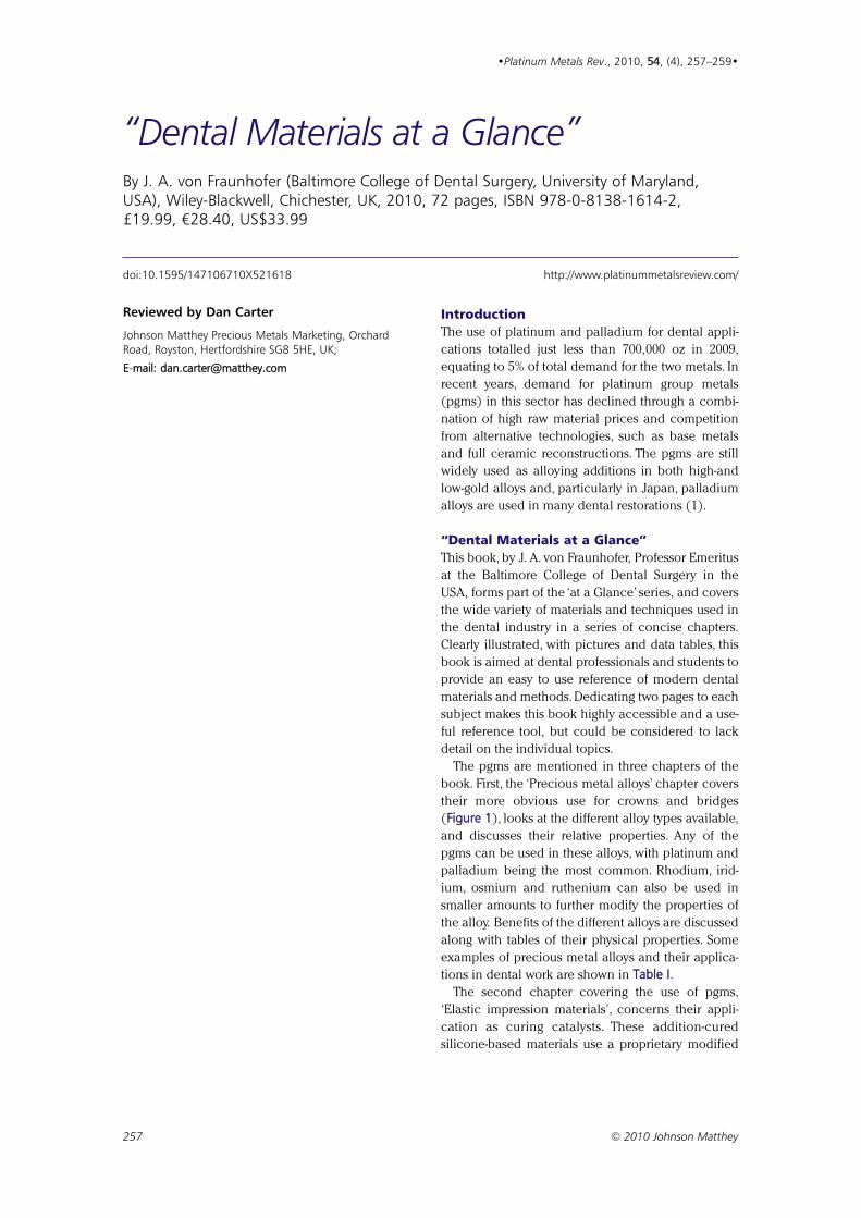
Reviewed by Dan Carter
Johnson Matthey Precious Metals Marketing, OrchardRoad, Royston, Hertfordshire SG8 5HE, UK;
E-mmail: [email protected]
IntroductionThe use of platinum and palladium for dental appli-
cations totalled just less than 700,000 oz in 2009,
equating to 5% of total demand for the two metals. In
recent years, demand for platinum group metals
(pgms) in this sector has declined through a combi-
nation of high raw material prices and competition
from alternative technologies, such as base metals
and full ceramic reconstructions. The pgms are still
widely used as alloying additions in both high-and
low-gold alloys and, particularly in Japan, palladium
alloys are used in many dental restorations (1).
“Dental Materials at a Glance”This book, by J. A. von Fraunhofer, Professor Emeritus
at the Baltimore College of Dental Surgery in the
USA, forms part of the ‘at a Glance’ series, and covers
the wide variety of materials and techniques used in
the dental industry in a series of concise chapters.
Clearly illustrated, with pictures and data tables, this
book is aimed at dental professionals and students to
provide an easy to use reference of modern dental
materials and methods. Dedicating two pages to each
subject makes this book highly accessible and a use-
ful reference tool, but could be considered to lack
detail on the individual topics.
The pgms are mentioned in three chapters of the
book. First, the ‘Precious metal alloys’ chapter covers
their more obvious use for crowns and bridges
(Figure 1), looks at the different alloy types available,
and discusses their relative properties. Any of the
pgms can be used in these alloys, with platinum and
palladium being the most common. Rhodium, irid-
ium, osmium and ruthenium can also be used in
smaller amounts to further modify the properties of
the alloy. Benefits of the different alloys are discussed
along with tables of their physical properties. Some
examples of precious metal alloys and their applica-
tions in dental work are shown in Table I.The second chapter covering the use of pgms,
‘Elastic impression materials’, concerns their appli-
cation as curing catalysts. These addition-cured
silicone-based materials use a proprietary modified
257 © 2010 Johnson Matthey
•Platinum Metals Rev., 2010, 54, (4), 257–259•
“Dental Materials at a Glance” By J. A. von Fraunhofer (Baltimore College of Dental Surgery, University of Maryland,USA), Wiley-Blackwell, Chichester, UK, 2010, 72 pages, ISBN 978-0-8138-1614-2,£19.99, €28.40, US$33.99
doi:10.1595/147106710X521618 http://www.platinummetalsreview.com/
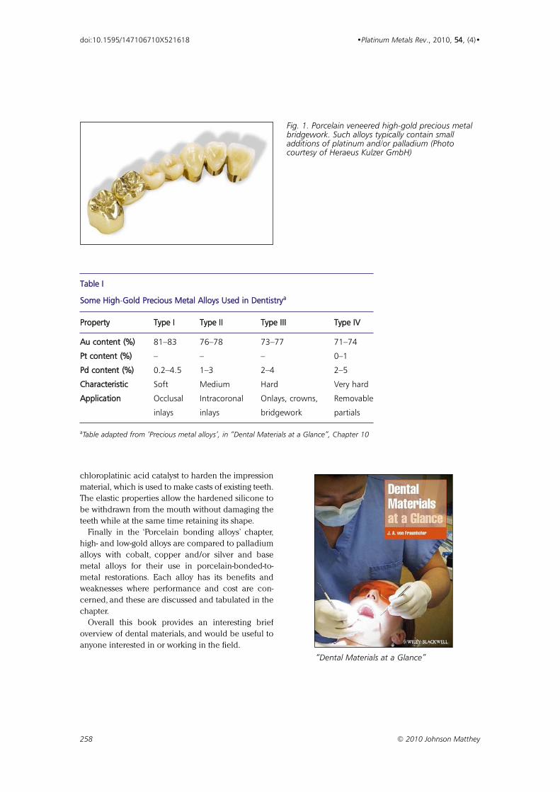
chloroplatinic acid catalyst to harden the impression
material, which is used to make casts of existing teeth.
The elastic properties allow the hardened silicone to
be withdrawn from the mouth without damaging the
teeth while at the same time retaining its shape.
Finally in the ‘Porcelain bonding alloys’ chapter,
high- and low-gold alloys are compared to palladium
alloys with cobalt, copper and/or silver and base
metal alloys for their use in porcelain-bonded-to-
metal restorations. Each alloy has its benefits and
weaknesses where performance and cost are con-
cerned, and these are discussed and tabulated in the
chapter.
Overall this book provides an interesting brief
overview of dental materials, and would be useful to
anyone interested in or working in the field.
258 © 2010 Johnson Matthey
doi:10.1595/147106710X521618 •Platinum Metals Rev., 2010, 54, (4)•
Table I
Some High-GGold Precious Metal Alloys Used in Dentistryaa
Property Type I Type II Type III Type IV
Au content (%) 81–83 76–78 73–77 71–74
Pt content (%) – – – 0–1
Pd content (%) 0.2–4.5 1–3 2–4 2–5
Characteristic Soft Medium Hard Very hard
Application Occlusal Intracoronal Onlays, crowns, Removable
inlays inlays bridgework partials
aTable adapted from ‘Precious metal alloys’, in “Dental Materials at a Glance”, Chapter 10
Fig. 1. Porcelain veneered high-gold precious metalbridgework. Such alloys typically contain smalladditions of platinum and/or palladium (Photocourtesy of Heraeus Kulzer GmbH)
“Dental Materials at a Glance”
259 © 2010 Johnson Matthey
doi:10.1595/147106710X521618 •Platinum Metals Rev., 2010, 54, (4)•
Palladium in DentistryPlatinum-containing high-gold alloys have been used by dentists for many decades but the use of
palladium in dentistry is relatively recent. It dates from the 1980s, when a rise in the price of gold encour-
aged palladium to be introduced as a lower-cost alternative.
In Japan, the government operates a specific mandate stating that all government-subsidised dental
alloys have to include a palladium content of 20%. This alloy is known as the kinpala alloy and is used in
around 90% of all Japanese dental treatment. Hence, Japan is the largest palladium-consuming region for
dental applications, followed by North America and then Europe.
From Platinum Today: http://www.platinum.matthey.com/applications/industrial-applications/dental/
The ReviewerDr Dan Carter graduated with an MChem(Hons) from the University of Wales,Swansea, UK, and a PhD in InorganicChemistry from the University ofNottingham, UK. He is currently SeniorAnalyst in the Johnson Matthey MarketResearch team, focusing on the automotive,electronics, fuel cell and dental sectors.
Reference1 D. Jollie, “Platinum 2010”, Johnson Matthey, Royston, UK,
2010: http://www.platinum.matthey.com/publications/pgm-market-reviews/archive/platinum-2010/ (Accessedon 26th August 2010)
260 © 2010 Johnson Matthey
doi:10.1595/147106710X536973 •Platinum Metals Rev., 2010, 54, (4), 260–262•
CATALYSIS – APPLIED AND PHYSICALASPECTSMicrobial Engineering of Nanoheterostructures:Biological Synthesis of a Magnetically RecoverablePalladium NanocatalystV. S. Coker, J. A. Bennett, N. D. Telling, T. Henkel, J. M.Charnock, G. van der Laan, R. A. D. Pattrick, C. I. Pearce, R.S. Cutting, I. J. Shannon, J. Wood, E. Arenholz, I. C. Lyon andJ. R. Lloyd, ACS Nano, 2010, 4, (5), 2577–2584
Pd nanoparticles were deposited onto a nanoscale
biogenic magnetite support without the need for pre-
treatment with a ligand.The support was synthesised
in a one-step process at ambient temperature by the
Fe(III)-reducing bacterium, Geobacter sulfurreducens.
The resulting Pd-magnetite catalyst showed ease of
recovery and high dispersion. Rates of reaction for
Heck coupling of iodobenzene to ethyl acrylate or
styrene were equal or superior to a commercial col-
loidal Pd catalyst.
Banana Peel Extract Mediated Novel Route for theSynthesis of Palladium NanoparticlesA. Bankar, B. Joshi, A. R. Kumar and S. Zinjarde, Mater. Lett.,2010, 64, (18), 1951–1953
Pd nanoparticles with average size 50 nm were syn-
thesised in a ‘green’ process by reducing PdCl2 using
boiled, crushed, acetone precipitated, air-dried
banana peel powder.The Pd nanoparticles were char-
acterised by UV–vis spectroscopy, SEM-EDS, XRD
analysis, DLS and FTIR spectroscopy.
Solid-SState NMR Characterization of Wilkinson’sCatalyst Immobilized in Mesoporous SBA-33 SilicaA. Grünberg, X. Yeping, H. Breitzke and G. Buntkowsky,Chem. Eur. J., 2010, 16, (23), 6993–6998
Wilkinson’s catalyst [RhCl(PPh3)3] was immobilised
inside the pores of amine functionalised meso-
porous silica material SBA-3. Successful modification
of the silica surface was confirmed by 29Si CP-MAS
NMR experiments. 31P-31P J-resolved 2D MAS NMR
experiments were used to characterise the binding
mode of the immobilised catalyst. Two PPh3 ligands
were found to be replaced and the catalyst was
bonded to the silica surface through the amine
groups of two linker molecules attached to the silica
surface.
Gaseous Fuel Production from Nonrecyclable PaperWastes by Using Supported Metal Catalysts in High-Temperature Liquid WaterA. Yamaguchi, N. Hiyoshi, O. Sato, K. K. Bando and M.Shirai, ChemSusChem, 2010, 3, (6), 737–741
Gasification of nonrecyclable paper wastes, such as
shredded documents and paper sludge, was carried
out in high-temperature liquid water over supported
Ru, Rh, Pt or Pd catalysts to produce CH4 and CO2,
with a small amount of H2.The order of catalytic activ-
ity was Ru > Rh >> Pt >> Pd.The most effective catalyst
was Ru/C. Paper wastes were gasified to a limited
degree (32.6 C%) for 30 min in water at 523 K. At
573 K,more complete gasification with almost 100 C%
was achieved within 10 min.
CATALYSIS – INDUSTRIAL PROCESSInvestigation of the Catalytic Activity of Rh–LaCoO33
Catalyst in the Conversion of Tar from BiomassDevolatilization ProductsP. Ammendola, R. Chirone, L. Lisi, B. Piriou and G. Russo,Appl. Catal. A: Gen., 2010, 385, (1–2), 123–129
An alumina-supported Rh–LaCoO3 catalyst can be
used to convert biomass devolatilisation products to
syngas in a double fixed bed reactor system.The reac-
tion was tested at temperatures 500–700ºC, Rh load-
ings 0.1–1 wt%, catalyst amount 0.25–1 g and N2 flow
rate 12–60 Nl h–1. Good performance was achieved at
600ºC. At 700ºC complete tar conversion could be
obtained with a Rh loading of 0.1 wt%, a catalyst
amount of 0.5 g or a carrier flow rate of 48 Nl h–1.
CATALYSIS – REACTIONSRapid Identification of a Scalable Catalyst for theAsymmetric Hydrogenation of a StericallyDemanding Aryl EnamideL. Lefort, J. A. F. Boogers, T. Kuilman, R. J. Vijn, J. Janssen, H.Straatman, J. G. de Vries and A. H. M. de Vries, Org. ProcessRes. Dev., 2010, 14, (3), 568–573
High-throughput screening was used to find a cost-
effective and scalable Rh-based catalyst with a bulky
monodentate phosphite ligand for the asymmetric
hydrogenation of a sterically demanding enamide as
an intermediate towards a new potent melanocortin
receptor agonist useful in the treatment of obesity.
Abstracts
The catalyst was scaled up and used in the kilogram
production of the desired bulky chiral amide.
Enhanced Bulk Catalyst Dissolution for Self-HHealingMaterialsT. C. Mauldin and M. R. Kessler, J. Mater. Chem., 2010, 20,(20), 4198–4206
A model was developed to aid in the selection of heal-
ing monomers that can rapidly dissolve catalysts in
self-healing materials. Predictions were made of disso-
lution rates of Grubbs’catalyst [Cl2(PCy3)2Ru(=CHPh)]
in a small library of ROMP-active norbornenyl-based
healing monomers. It was observed that healing
monomers and blends of monomers with Hansen
parameters similar to the catalyst were able to rapidly
dissolve the catalyst. Increasing the dissolution rate of
the catalyst allows less overall catalyst to achieve sim-
ilar levels of healing, making Grubbs’ catalyst poten-
tially more economic for use.
EMISSIONS CONTROLIn Situ Synthesis of Platinum Nanocatalysts on aMicrostructured Paperlike Matrix for the CatalyticPurification of Exhaust GasesH. Koga, Y. Umemura, A. Tomoda, R. Suzuki and T. Kitaoka,ChemSusChem, 2010, 3, (5), 604–608
Pt nanoparticles (PtNPs) on a microstructured paper-
like matrix of ceramic fibre and zinc oxide whiskers
(PtNPs@ZnO “paper”) were synthesised in situ. Good
catalytic performance was demonstrated for the
reduction of NOx with propene for exhaust gas purifi-
cation, at a low reaction temperature and with one-
third the dosage of Pt compared to conventional Pt-
loaded honeycomb catalysts.
Sulfur Release from a Model Pt/Al22O33 DieselOxidation Catalyst: Temperature-PProgrammed andStep-RResponse Techniques CharacterizationJ.-Y. Luo, D. Kisinger, A. Abedi and W. S. Epling, Appl. Catal.A: Gen., 2010, 383, (1–2), 182–191
The desulfation process of a model Pt/Al2O3 DOC was
investigated using temperature-programmed tech-
niques and step-response methods. Desulfation was
promoted under reducing conditions.H2O further pro-
moted desulfation while CO2 had no obvious effect.
Higher H2 concentrations generated more H2S. The
desulfation process could be viewed as a stepwise
reduction of sulfates to SO2 and then to H2S. A S load-
ing equivalent to 3 g l–1 gave the largest SO2:H2S ratio.
METALLURGY AND MATERIALSAtomic-LLevel Pd–Pt Alloying and Largely EnhancedHydrogen-SStorage Capacity in Bimetallic NanoparticlesReconstructed from Core/Shell Structure by a Processof Hydrogen Absorption/DesorptionH. Kobayashi, M. Yamauchi, H. Kitagawa, Y. Kubota, K. Katoand M. Takata, J. Am. Chem. Soc., 2010, 132, (16), 5576–5577
Solid-solution homogeneous PdPt nanoparticles, 1,
containing ~21 at% Pt were formed from core/shell
nanoparticles with a Pd core of diameter 6.1 ± 0.1 nm
and a Pt shell of thickness ~1.1 nm by a process of H2
absorption/desorption at 373 K. No size growth was
observed during the process. 1 had a higher H2-stor-
age capacity than Pd nanoparticles and this could be
tuned by changing the alloy composition.
Microstructure and Corrosion of Pd-MModified TiAlloys Produced by Powder MetallurgyM. A. Ashworth, A. J. Davenport, R. M. Ward and H. G. C.Hamilton, Corros. Sci., 2010, 52, (7), 2413–2421
Ti alloy parts with enhanced corrosion resistance
were fabricated by a powder metallurgy route.
Commercial purity Ti powders were modified with
0.15 wt% Pd and hot isostatically pressed (HIPped).
The microstructure and distribution of the Pd was
characterised by optical microscopy and SEM. The
phase composition and electrochemistry of the
HIPped Pd-modified alloy was equivalent to that of
wrought Grade 7 Ti (which contains 0.12–0.25 wt%
Pd). This route overcomes the need to source and
maintain an inventory of expensive Pd-modified
grades of Ti and allows “on-demand” modification of
powders with the level of Pd tailored towards the tar-
get application.
APPARATUS AND TECHNIQUEInactivation and Mineralization of Aerosol DepositedModel Pathogenic Microorganisms over TiO22 andPt/TiO22
E. A. Kozlova, A. S. Safatov, S. A. Kiselev, V. Yu. Marchenko,A. A. Sergeev, M. O. Skarnovich, E. K. Emelyanova, M. A.Smetannikova, G. A. Buryak and A. V. Vorontsov, Environ.Sci. Technol., 2010, 44, (13), 5121–5126
Air disinfection from bacteria and viruses was carried
out on undoped TiO2 and on platinised sulfated TiO2
(Pt/TiO2) under UVA irradiation and in the dark. ~90%
inactivation was achieved after 30 min irradiation on
TiO2 and 90–99.8% on Pt/TiO2. The rate of photocat-
alytic CO2 production increased with both cell mass
261 © 2010 Johnson Matthey
doi:10.1595/147106710X536973 •Platinum Metals Rev., 2010, 54, (4)•
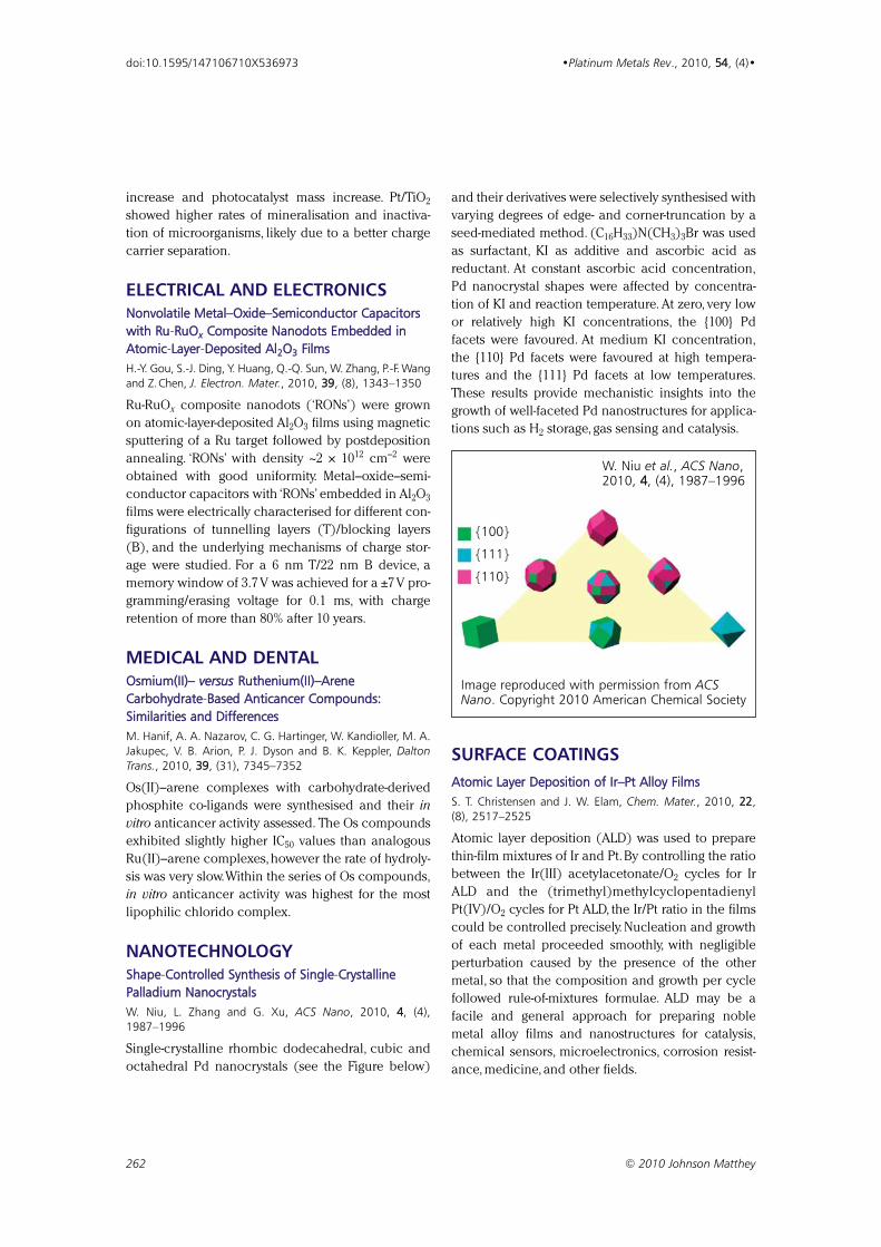
increase and photocatalyst mass increase. Pt/TiO2
showed higher rates of mineralisation and inactiva-
tion of microorganisms, likely due to a better charge
carrier separation.
ELECTRICAL AND ELECTRONICSNonvolatile Metal–Oxide–Semiconductor Capacitorswith Ru-RRuOxx Composite Nanodots Embedded inAtomic-LLayer-DDeposited Al22O33 FilmsH.-Y. Gou, S.-J. Ding, Y. Huang, Q.-Q. Sun, W. Zhang, P.-F. Wangand Z.Chen, J. Electron. Mater., 2010, 39, (8), 1343–1350
Ru-RuOx composite nanodots (‘RONs’) were grown
on atomic-layer-deposited Al2O3 films using magnetic
sputtering of a Ru target followed by postdeposition
annealing. ‘RONs’ with density ~2 × 1012 cm–2 were
obtained with good uniformity. Metal–oxide–semi-
conductor capacitors with ‘RONs’ embedded in Al2O3
films were electrically characterised for different con-
figurations of tunnelling layers (T)/blocking layers
(B), and the underlying mechanisms of charge stor-
age were studied. For a 6 nm T/22 nm B device, a
memory window of 3.7 V was achieved for a ±7 V pro-
gramming/erasing voltage for 0.1 ms, with charge
retention of more than 80% after 10 years.
MEDICAL AND DENTALOsmium(II)– versus Ruthenium(II)–AreneCarbohydrate-BBased Anticancer Compounds:Similarities and DifferencesM. Hanif, A. A. Nazarov, C. G. Hartinger, W. Kandioller, M. A.Jakupec, V. B. Arion, P. J. Dyson and B. K. Keppler, DaltonTrans., 2010, 39, (31), 7345–7352
Os(II)–arene complexes with carbohydrate-derived
phosphite co-ligands were synthesised and their in
vitro anticancer activity assessed. The Os compounds
exhibited slightly higher IC50 values than analogous
Ru(II)–arene complexes, however the rate of hydroly-
sis was very slow.Within the series of Os compounds,
in vitro anticancer activity was highest for the most
lipophilic chlorido complex.
NANOTECHNOLOGYShape-CControlled Synthesis of Single-CCrystallinePalladium NanocrystalsW. Niu, L. Zhang and G. Xu, ACS Nano, 2010, 4, (4),1987–1996
Single-crystalline rhombic dodecahedral, cubic and
octahedral Pd nanocrystals (see the Figure below)
and their derivatives were selectively synthesised with
varying degrees of edge- and corner-truncation by a
seed-mediated method. (C16H33)N(CH3)3Br was used
as surfactant, KI as additive and ascorbic acid as
reductant. At constant ascorbic acid concentration,
Pd nanocrystal shapes were affected by concentra-
tion of KI and reaction temperature. At zero, very low
or relatively high KI concentrations, the {100} Pd
facets were favoured. At medium KI concentration,
the {110} Pd facets were favoured at high tempera-
tures and the {111} Pd facets at low temperatures.
These results provide mechanistic insights into the
growth of well-faceted Pd nanostructures for applica-
tions such as H2 storage, gas sensing and catalysis.
SURFACE COATINGSAtomic Layer Deposition of Ir–Pt Alloy FilmsS. T. Christensen and J. W. Elam, Chem. Mater., 2010, 22,(8), 2517–2525
Atomic layer deposition (ALD) was used to prepare
thin-film mixtures of Ir and Pt. By controlling the ratio
between the Ir(III) acetylacetonate/O2 cycles for Ir
ALD and the (trimethyl)methylcyclopentadienyl
Pt(IV)/O2 cycles for Pt ALD, the Ir/Pt ratio in the films
could be controlled precisely. Nucleation and growth
of each metal proceeded smoothly, with negligible
perturbation caused by the presence of the other
metal, so that the composition and growth per cycle
followed rule-of-mixtures formulae. ALD may be a
facile and general approach for preparing noble
metal alloy films and nanostructures for catalysis,
chemical sensors, microelectronics, corrosion resist-
ance, medicine, and other fields.
262 © 2010 Johnson Matthey
doi:10.1595/147106710X536973 •Platinum Metals Rev., 2010, 54, (4)•
{100}
{111}
{110}
W. Niu et al., ACS Nano,2010, 4, (4), 1987–1996
Image reproduced with permission from ACSNano. Copyright 2010 American Chemical Society
263 © 2010 Johnson Matthey
doi:10.1595/147106710X534443 •Platinum Metals Rev., 2010, 54, (4), 263–265•
CATALYSIS – APPLIED AND PHYSICALASPECTSClean Production of Solid Ruthenium ComplexJohnson Matthey PLC, World Appl. 2010/064,045
A cationic Ru complex is produced by reacting a
[Ru(arene)(halogen)2]2 with a 4,4'-bis(disubstituted-
phosphino)-3,3'-bipyridine ligand in at least one alco-
hol with boiling point <120ºC at 1 atm. Preferred
arenes are benzene, p-cymene or 1,3,5-trimethylben-
zene; halogens are Cl, Br or I and ligands are PPhos,
TolPPhos and XylPPhos. The complex may be used as
a hydrogenation catalyst without solvent change.
Further, a C1–10 alkane may be added to produce a
solid complex, which exhibits improved stability over
complexes precipitated with solvents such as MBTE.
Hydrothermally-PPrepared Rhodium on ZeoliteNippon Chem. Ind. Co, Ltd, Japanese Appl. 2010-029,787
A hydrothermal method for producing a catalyst with
>1 wt% Rh highly dispersed on zeolite is claimed. An
aqueous slurry of a high-silica zeolite; a water-soluble
Rh salt, preferably Rh(III) nitrate; and a source of
either tetraethylammonium or tetrapropylammonium
as a templating agent, preferably tetraethylammoni-
um hydroxide, is prepared. The molar ratio of water,
Rh and templating agent is 1–50:0.001–0.03:0.01–1,
based on Si in the zeolite. The mixture,with pH 10–14,
is then treated at 140–180ºC for ~40–70 h.
CATALYSIS – INDUSTRIAL PROCESSPGM Catalyst for Upgrading Middle DistillatesTotal Raffinage Marketing SA, World Appl. 2010/079,044
A feedstock such as light cycle oil with CI ≤40,CN ≤35,
100 ppm ≤ N ≤ 1200 ppm, 200 ppm ≤ S ≤ 2.5 wt% and
aromatics ≥50 wt%, is in a first step passed over an
HDS/HDN catalyst such as NiMo/Al2O3. The effluent,
optionally stripped, is then hydrodearomatised over a
catalyst containing 0.25–1 wt% of each of Pt and Pd
highly dispersed on a SiO2–Al2O3 carrier with a pore
volume of 0.6 ml g–1 and a surface area of 300 m2 g–1.
Reaction conditions are typically 0.5–1.2 h–1 LHSV,
250–320ºC and 45–65 bar gauge pressure. The
product obtained may have S ≤1 ppm, N ≤1 ppm, aro-
matics ≤2 wt%, 35 ≤ CI ≤ 43 and 40 ≤ CN ≤ 48, and is
suitable for use in a diesel pool at ≥50 wt%.
CATALYSIS – REACTIONSPhosphorus-FFree Rhodium Hydrogenation CatalystSchlumberger Technol. Corp, US Appl. 2010/0,168,454
Hydrogenation of C=C or C=N bonds in organic
compounds is carried out in the presence of a Rh
complex with non-phosphine ligands A and B,where
A is a heterocyclic organic base, 1, preferably 1aand particularly 1,8-diazabicyclo[5.4.0]undec-7-ene
(DBU), 1b, or 1,5-diazabicyclo[5.3.0]non-5-ene
(DBN),1c ,and B is a cycloaliphatic diene,preferably
1,5-cyclooctadiene (COD).
EMISSIONS CONTROLThree-WWay Catalyst with Improved Sulfur ToleranceToyota Central Res. Dev. Labs, Inc, Japanese Appl. 2010-051,847
A dual-layer catalyst has: a first layer with 0.01–5 wt%
Pt supported on CeO2–ZrO2 (≥45 wt% CeO2) and
Al2O3 (≤0.1 wt% TiO2); and a second layer with
0.01–5 wt% Rh supported on CeO2–ZrO2 (4–35 wt%
CeO2) and TiO2–Al2O3 (5–20 wt% TiO2). This formula-
tion of the compound oxides is found to control S
poisoning to limit formation of H2S and further pre-
vents degradation of OSC performance during high-
temperature operation.
Patents
R3
R2
R1N
N
R1
N
NR4
N N
US Appl. 2010/0,168,454
1
R1 = substituted or unsubstituted C2–8,preferably C2 or C3, hydrocarbon
R2, R3 = substituted/unsubstituted hydrocarbonR4 = aliphatic C2–10, preferably C3–5,
hydrocarbon
R1 and R4 may be aromatic or saturated aliphaticgroups and may have side-chain groups which arethemselves aliphatic, such as C1–4 alkyls
1a
1c: DBN1b: DBU
N N
Catalyst for Removal of CO from Motorcycle ExhaustCataler Corp, Japanese Appl. 2010-058,069
A catalyst suitable for low-temperature use in motor-
cycles consists of a honeycomb substrate with two
sections. The first stage has loadings (per litre sub-
strate): 1–10 g Pd, preferably 2.5–6 g Pd; and 0.05–5 g
Rh,preferably 0.15–1.5 g Rh. The second, downstream
stage has loadings (per litre substrate): 0 g Pd and
0.05–5 g Rh, preferably 0.15–1.5 g Rh. The Pd in the
first stage acts to raise the temperature of the exhaust
gas, promoting oxidation of CO in the second stage,
even under rich exhaust conditions.
FUEL CELLSQuarternary Fuel Cell CatalystUTC Power Corp, World Appl. 2010/050,964
An alloy has composition PtwVxMy Irz, where (in
mol%): 30 ≤ w ≤ 75,5 ≤ x ≤ 50,5 ≤ y ≤ 50 and 5 ≤ z ≤ 30,
and M is one or a combination of Co, Ti, Cr, Mn,
Fe, Ni, Cu, Zn, Mo and W. Specifically, the alloy
is Pt40V20Co30Ir10 and is deposited at 10–70 wt% load-
ing on a C support as particles 2–20 nm in size. As a
cathode catalyst in a PEMFC,PAFC,SOFC or other fuel
cell, the alloy is durable and has high ORR activity.
Platinum Mesh for Strengthening SOFCShinko Electr. Ind. Co, Ltd, US Patent 7,722,980 (2010)
A SOFC system has a cathode electrode layer and an
anode electrode layer formed on opposite faces of a
single solid oxide substrate, with both layers contain-
ing an embedded Pt mesh and the whole encased in
an oxide layer formed from a solid electrolyte.The Pt
mesh and oxide layer prevent cracking of the cell due
to thermal shock,allowing the system to be heated by
direct exposure to a flame with rapid start-up.The Pt
meshes may also be connected to lead wires and
function as current-collecting electrodes.
METALLURGY AND MATERIALSMultilayer Coating for Costume JewelleryUmicore Galvanotechnik GmbH, World Appl. 2010/057,573
A base metal blank is successively plated with:
(a) an optional first layer of 15–20 µm Cu;(b) a 1–3 µm
layer of preferably pure Pd; (c) an optional intermedi-
ate layer of 0.1–0.2 µm Au; and (d) a 0.1–0.5 µm layer
of either Pt-Ru with 60–75 wt% Pt, or Rh-Ru with
70–80 wt% Rh. Layers (b) and (d) are preferably
deposited by rack coating. The coating is found to
have abrasion resistance which is much higher than
the average resistance of the metals in (d). Good
colour and brightness are also obtained.
Rhodium Alloy for Gas Turbine RepairGeneral Electric Co, US Patent 7,722,729 (2010)
An alloy with improved high-temperature perform-
ance is composed of (in at%): (a) ≥50% Rh; (b) ≤49%
of one of Pt, Pd, Ir (or a combination); (c) 1–15%,
preferably 1–6%, W and/or Re; (d) ≤10%, preferably
≤8%,Ru and/or Cr; and,optionally (e) ≤3%,preferably
≤2%, one or more of Zr,Y, Hf, Ta,Al,Ti, Sc, a lanthanide
and an actinide. The sum of (a) and (b) is ≥75%,
preferably ≥85%. The alloy contains ≥90 vol% of the
A1-structured phase at >1000ºC. A method of using
the alloy to repair components such as the blade tip,
leading and trailing edges is also claimed.
Low-MMelting Palladium SolderK. Weinstein, US Patent 7,722,806 (2010)
A solder for use with Ni-free white Au and Pd jewellery
consists of 85–95 wt% Pd and the balance a mixture of
Ga and In in a weight ratio of ~7:3, with the composi-
tion tuned to attain the desired hardness for each
application.When used with white Au, the solder may
contain the carated amount of Au with the balance a
mixture of Pd,Ag,Cu,Zn,Ga and In.The solder melts at
~1200–1300ºC,making it particularly suitable for repair
and resizing of Au and Pd jewellery.
ELECTRICAL AND ELECTRONICSNanoelectromechanical Switch with Ruthenium BeamSandia Corp, US Patent 7,719,318 (2010)
A NEM switch is formed on a Si substrate by: suspend-
ing a beam of Ru between two anchor points to form
the source electrode, 1; positioning one drain elec-
trode, 2, or a pair thereof at the midpoint of the beam
but laterally offset by a 20–75 nm gap; positioning one
or two pairs of electrically-connected gate electrodes,
3, around the midpoint of the beam but offset by a
30–100 nm gap. The Ru beam is ≤10 µm long and
≤0.1 µm wide and bows laterally towards 2 in
response to an actuation voltage applied across 1and 3, thus forming a connection between 1 and 2. A
RuO2 coating can be applied to 1 to prevent fouling
of contact surfaces. The switch can be used to form
fast-response NAND and NOR gates or SRAM and
DRAM memory cells.
264 © 2010 Johnson Matthey
doi:10.1595/147106710X534443 •Platinum Metals Rev., 2010, 54, (4)•
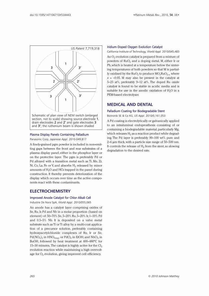
Plasma Display Panels Containing PalladiumPanasonic Corp, Japanese Appl. 2010-049,817
A finely-grained pgm powder is included in non-emit-
ting gaps between the front and rear substrates of a
plasma display panel, either in the phosphor layer or
on the protective layer. The pgm is preferably Pd or
Pd alloyed with a transition metal such as Ti, Mn, Zr,
Ni, Co, La, Fe or V, and absorbs H2 released by minor
amounts of H2O and HCs trapped in the panel during
construction. It thereby prevents deterioration of the
display which occurs over time as the active compo-
nents react with these contaminants.
ELECTROCHEMISTRYImproved Anode Catalyst for Chlor-AAlkali CellIndustrie De Nora SpA, World Appl. 2010/055,065
An anode has a catalyst layer comprising oxides of
Sn, Ru, Ir, Pd and Nb in a molar proportion (based on
element) of: 50–70% Sn,5–20% Ru,5–20% Ir,1–10% Pd
and 0.5–5% Nb. It is deposited on a valve metal
substrate such as Ti or Ti alloy by a multi-coat applica-
tion of a precursor solution, preferably containing
hydroxyacetylchloride complexes of Ru, Ir or Sn;
Pd(NO3)2 in HNO3(aq) or PdCl2 in EtOH; and NbCl5 in
BuOH, followed by heat treatment at 400–480ºC for
15–30 minutes. The catalyst is highly active for the Cl2
evolution reaction while maintaining a high overvolt-
age for O2 evolution, giving improved cell efficiency.
Iridium-DDoped Oxygen Evolution CatalystCalifornia Institute of Technology, World Appl. 2010/045,483
An O2 evolution catalyst is prepared from a mixture of
powders of RuO2 and a doping metal, M, either Ir or
Pb,which is heated at a temperature below the sinter-
ing temperatures of both powders so that M is partial-
ly oxidised by the RuO2 to produce MOxRuO2–x where
x = ~0.05. M may also be present in the catalyst at
5–25 at%, preferably 9–12 at%. The doped Ru oxide
catalyst is found to be stable in acidic media and is
suitable for use in the anodic oxidation of H2O in a
PEM-based electrolyser.
MEDICAL AND DENTALPalladium Coating for Biodegradable StentBiotronik SE & Co KG, US Appl. 2010/0,161,053
A Pd coating is electrolytically or galvanically applied
to an intraluminal endoprosthesis consisting of or
containing a biodegradable material, particularly Mg,
which releases H2 as a reaction product while degrad-
ing. The Pd layer is preferably 90–100 wt% pure and
2–6 µm thick,with a particle size range of 50–500 nm.
It controls the release of H2 from the stent, so slowing
degradation to the desired rate.
265 © 2010 Johnson Matthey
doi:10.1595/147106710X534443 •Platinum Metals Rev., 2010, 54, (4)•
1
1
2 2’
3’3
3 3’
US Patent 7,719,318
Schematic of plan view of NEM switch (enlargedsection, not to scale) showing source electrode 1,drain electrodes 2 and 2’ and gate electrodes 3and 3’; the ruthenium beam is shown shaded
A previous “Final Analysis”in this two-part series intro-
duced the thermodynamics of platinum and dis-
cussed methods of casting platinum and its alloys for
jewellery use (1). Here welding as a means of assem-
bling cast platinum components into finished prod-
ucts is discussed.
Welding: A Miniature Casting Operation
Casting section by section and welding reduces the
amount of expensive platinum alloy in process at
any time. Because of its low thermal diffusivity (1),
platinum can be assembled by precision welding
very satisfactorily. The same welding systems may be
very useful in cleaning up minor casting defects and
for jewellery repair. Adjusting the power density to
precise targets is more quickly learned than with tra-
ditional torch welding but the capital cost of such
precision welding systems has to be considered.
Welding is a miniature casting operation; much the
same heat flow arguments apply. The least expensive
capital option is a torch with bottled oxy-acetylene,
-natural gas or -butane. The possibility of carbon pick-
up from reducing flame conditions is not great
because a reducing flame is scarcely adequate for
platinum welding temperatures and is therefore easi-
ly avoided. An oxy-hydrogen torch is cleaner but
lacks luminosity until boosted by running the gas
through denatured alcohol. Without luminosity the
torch is more difficult to work with, as the very pale
blue flame is almost invisible against the increasingly
reflective background of platinum as it is heated. One
of the most popular oxy-hydrogen generators and
torch welders was developed by Johnson Matthey
and is now manufactured by Sherwood Scientific Ltd
(2) and sold widely by distributors including A G
Thomas (Bradford) Ltd for between £1000–£2000
dependent on unit size (FFiigguurree 11) (3–5). Flame torch-
es lose a lot of heat to surroundings; precise control
requires frequent jet/nozzle and fuel flow changes.
Platinum Jewellery Welding
Electric welding is very effective with platinum group
metal (pgm) jewellery alloys using single-phase
mains input power less than 1.7 kW. The brief peak
power of the pulse focused on a sub-millimetre target
(it can be as small as 20 µm with the laser beam)
produces a high power density relative to the small
volume of metal. The relatively low thermal diffusivity
of the pgms (1) restricts the heat-affected zone very
effectively. Pulse argon arc welders such as Lampert
Werktechnik GmbH’s PUK® machines based on
tungsten inert gas (TIG) arc welding technology are
very versatile, easy to learn to use and less than a
third of the price of a low-end laser. The best
equipped jewellery makers may use both PUK and
laser welders in slightly different ways. The PUK
welder pulls the arc into the target; while the laser
‘probes’. The PUK welder electrode can usually be
manoeuvred around larger objects than the laser; the
pulsing rate is slower than the laser. Where a lot of
welding or filler metal is needed such as in spun hol-
low ware the pulsing becomes virtually continuous
TIG arc welding (6) often with a jig or rotor. Welds
can be planished and polished.
The price of jewellery laser welders has fallen to
under £20,000 and there is a new generation of com-
pact ‘table top’ machines at about £16,000. In the US,
Rio Grande is the largest supplier of laser welders
and they market a tabletop version under the brand
name PulsePointTM StudioTM from Neutec USA
(FFiigguurree 22) (7). There is also a machine on the mar-
ket which offers an advanced constant voltage
power supply that allows welding at a substantially
reduced peak power; avoiding high peak power
pulses doubles the life of the expensive laser flash
tube.
Conclusions
In the last twenty years the jewellery industry has
adopted sophisticated techniques for melting, cast-
ing and joining the platinum group metals. This has
been achieved by matching the heat energy density
to an optimum geometry target. Highly localised
welding power is achieved by pulsing and very fine
focusing on targets frequently less than a millimetre
in diameter.
266 © 2010 Johnson Matthey
doi:10.1595/147106710X521915 •Platinum Metals Rev., 2010, 5544, (4), 266–268•
Melting the PGMs: The State of the Artin Welding Platinum
FFIINNAALL AANNAALLYYSSIISS
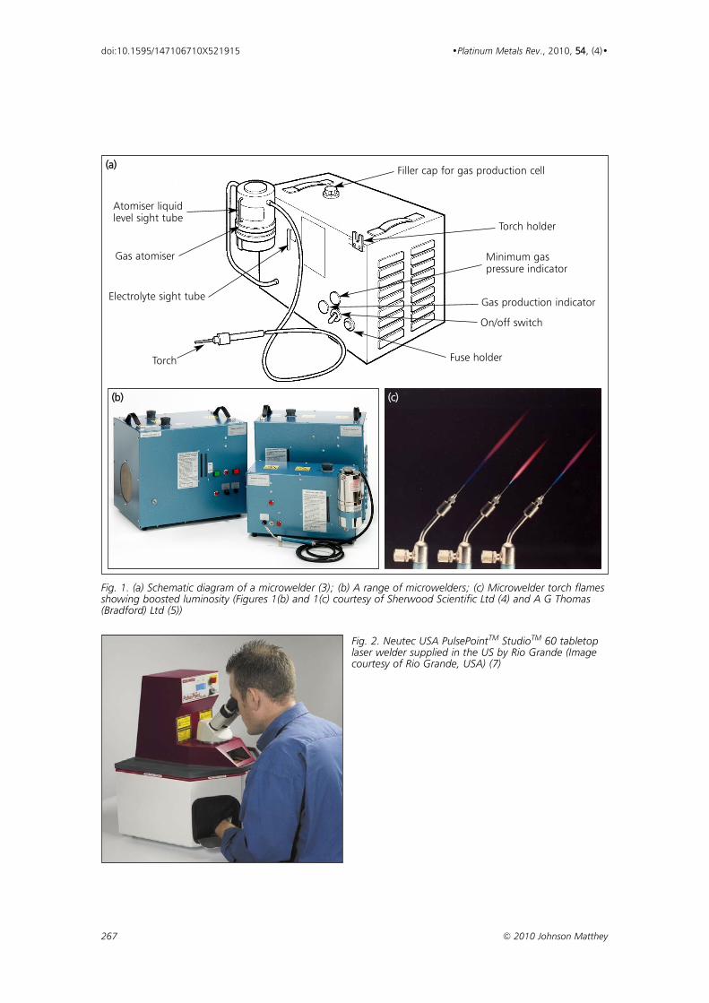
267 © 2010 Johnson Matthey
doi:10.1595/147106710X521915 •Platinum Metals Rev., 2010, 5544, (4)•
Torch holder
On/off switch
Fuse holderTorch
Filler cap for gas production cell
Gas production indicator
Minimum gaspressure indicator
Electrolyte sight tube
Gas atomiser
Atomiser liquidlevel sight tube
((aa))
((bb)) ((cc))
Fig. 1. (a) Schematic diagram of a microwelder (3); (b) A range of microwelders; (c) Microwelder torch flamesshowing boosted luminosity (Figures 1(b) and 1(c) courtesy of Sherwood Scientific Ltd (4) and A G Thomas(Bradford) Ltd (5))
Fig. 2. Neutec USA PulsePointTM StudioTM 60 tabletoplaser welder supplied in the US by Rio Grande (Imagecourtesy of Rio Grande, USA) (7)
in Nashville, Tennessee, USA, 10th–13th September,
2006, Met-Chem Research Inc, Albuquerque, New
Mexico, USA, 2006
7 Rio Grande Jewelry Making Supplies: http://www.
riogrande.com/ (Accessed on 16th August 2010)
JOHN C. WRIGHT
The Author
John Wright is a former Professor ofIndustrial Metallurgy at the University ofAston in Birmingham, UK. Currently, he is aconsultant for the jewellery industry world-wide with Wilson-Wright Associates. He isalso the author of the Johnson Matthey jew-ellery technical manual “An Introduction toPlatinum”.
268 © 2010 Johnson Matthey
doi:10.1595/147106710X521915 •Platinum Metals Rev., 2010, 5544, (4)•
1 J. C. Wright, Platinum Metals Rev., 2010, 5544, (2), 133
2 Sherwood Scientific Ltd, History: http://www.sherwood-
scientific.com/history.html (Accessed on 12th August
2010)
3 Johnson Matthey New York, Technical Information,
Platinum Manual, 4. Soldering and welding: http://www.
johnsonmattheyny.com/technical/platinumTechManual
(Accessed on 12th August 2010)
4 Sherwood Scientific Ltd, Product Index, Microwelder:
http://www.sherwood-scientific.com/microweld/
shmweld.html (Accessed on 12th August 2010)
5 A G Thomas (Bradford) Ltd, Microweld Solder Units:
http://www.agthomas.co.uk/Microweld.htm (Accessed
on 12th August 2010)
6 K. Lindsey, ‘TIG-Welding of Precious Metal’, in “The Santa Fe
Symposium on Jewelry Manufacturing Technology 2006”,
ed. E. Bell, Proceedings of the 20th Santa Fe Symposium®
References

EDITORIAL TEAM
Jonathan ButlerPublications Manager
Sara ColesAssistant Editor
Margery RyanEditorial Assistant
Keith WhiteSenior Information Scientist
E-mail: [email protected]
Platinum Metals Review is the quarterly E-journal supporting research on the science and technology of the platinum group metals and developments in their application in industry
http://www.platinummetalsreview.com/
Platinum Metals ReviewJohnson Matthey PLC, Precious Metals Marketing, Orchard Road, Royston, Hertfordshire SG8 5HE, UK
E-mail: [email protected]://www.platinummetalsreview.com/