pix packing list - sound devicescdn.sounddevices.com/download/guides/4268.004.pdf · pix packing...
TRANSCRIPT

PIX Packing List
Thank you for purchasing the PIX Video Recorder. Please make certain that this package contains the listed items below.
1) PIX Video Recorder
1) Universal In-Line Power Supply; 100–240 VAC input, 12 VDC/45 watt output
1) 1/4-20 Simple Stand
1) Printed User Guide and Technical Documentation
1) Purchase Registration Card
April, 2012


PIX 220 & PIX 240User Guide and Technical Information
Firmware rev. 2.0
Sound Devices, LLC E7556 State Rd. 23/33 • Reedsburg, WI • USA +1 (608) 524-0625 • fax: +1 (608) 524-0655 Toll-Free: (800) 505-0625 www.sounddevices.com [email protected]

PIX 220/PIX 240 User Guide and Technical Information
Introduction . . . . . . . . . . . . . . . . . . . . . . . . . . . . . . . . . . iiManual Conventions . . . . . . . . . . . . . . . . . . . . . . . . . . . . . . . . ii
Front Panel Descriptions . . . . . . . . . . . . . . . . . . . . . . . 1Top and Bottom Panel Descriptions . . . . . . . . . . . . . . 2Right Panel Descriptions . . . . . . . . . . . . . . . . . . . . . . . 3Left Panel Descriptions . . . . . . . . . . . . . . . . . . . . . . . . . 4Rear Panel Descriptions . . . . . . . . . . . . . . . . . . . . . . . . 5PIX-CADDY (Optional) . . . . . . . . . . . . . . . . . . . . . . . . . . 6Powering . . . . . . . . . . . . . . . . . . . . . . . . . . . . . . . . . . . . . 7
Removable Li-Ion Batteries . . . . . . . . . . . . . . . . . . . . . . . . . . . 7Li-Ion Battery Charging . . . . . . . . . . . . . . . . . . . . . . . . . . . . . . 7
Menu and Navigation . . . . . . . . . . . . . . . . . . . . . . . . . . 7Main View . . . . . . . . . . . . . . . . . . . . . . . . . . . . . . . . . . . . . . . . . 7Menu . . . . . . . . . . . . . . . . . . . . . . . . . . . . . . . . . . . . . . . . . . . . 8Audio . . . . . . . . . . . . . . . . . . . . . . . . . . . . . . . . . . . . . . . . . . . . 9Files . . . . . . . . . . . . . . . . . . . . . . . . . . . . . . . . . . . . . . . . . . . . 10LCD . . . . . . . . . . . . . . . . . . . . . . . . . . . . . . . . . . . . . . . . . . . . 10
Video Inputs . . . . . . . . . . . . . . . . . . . . . . . . . . . . . . . . 11HDMI . . . . . . . . . . . . . . . . . . . . . . . . . . . . . . . . . . . . . . . . . . . 11SDI . . . . . . . . . . . . . . . . . . . . . . . . . . . . . . . . . . . . . . . . . . . . 11
Video Outputs . . . . . . . . . . . . . . . . . . . . . . . . . . . . . . . 11Audio Inputs . . . . . . . . . . . . . . . . . . . . . . . . . . . . . . . . 12
Analog Audio Inputs . . . . . . . . . . . . . . . . . . . . . . . . . . . . . . . . 12Digital Audio Inputs . . . . . . . . . . . . . . . . . . . . . . . . . . . . . . . . 12Input Linking . . . . . . . . . . . . . . . . . . . . . . . . . . . . . . . . . . . . . . 13Choosing Audio Sources . . . . . . . . . . . . . . . . . . . . . . . . . . . . 13Input Level Control . . . . . . . . . . . . . . . . . . . . . . . . . . . . . . . . 14
Audio Outputs . . . . . . . . . . . . . . . . . . . . . . . . . . . . . . . 15Analog 5-Pin XLR Output . . . . . . . . . . . . . . . . . . . . . . . . . . . . 15Embedded Audio on HDMI and SDI . . . . . . . . . . . . . . . . . . . 15Headphone Output . . . . . . . . . . . . . . . . . . . . . . . . . . . . . . . . . 15
Video Monitoring Features . . . . . . . . . . . . . . . . . . . . . 16Exposure Assist . . . . . . . . . . . . . . . . . . . . . . . . . . . . . . . . . . . 16Focus Assist . . . . . . . . . . . . . . . . . . . . . . . . . . . . . . . . . . . . . . 18Zoom . . . . . . . . . . . . . . . . . . . . . . . . . . . . . . . . . . . . . . . . . . . 20Flip . . . . . . . . . . . . . . . . . . . . . . . . . . . . . . . . . . . . . . . . . . . . . 20
Recording . . . . . . . . . . . . . . . . . . . . . . . . . . . . . . . . . . 20Selecting File Resolution and Frame Rate . . . . . . . . . . . . . . . 21Selecting a Video Codec . . . . . . . . . . . . . . . . . . . . . . . . . . . . 21Interruption of Signal During Recording . . . . . . . . . . . . . . . . . 22Alignment of Audio and Video . . . . . . . . . . . . . . . . . . . . . . . . 22
Video Scaling and Frame Rate Conversion . . . . . . . 22Playback . . . . . . . . . . . . . . . . . . . . . . . . . . . . . . . . . . . . 23
Playback Mode . . . . . . . . . . . . . . . . . . . . . . . . . . . . . . . . . . . . 23Shuttle Mode . . . . . . . . . . . . . . . . . . . . . . . . . . . . . . . . . . . . . 24Cue Points . . . . . . . . . . . . . . . . . . . . . . . . . . . . . . . . . . . . . . . 24Looping . . . . . . . . . . . . . . . . . . . . . . . . . . . . . . . . . . . . . . . . . 24Playing Back Files on a Computer . . . . . . . . . . . . . . . . . . . . 25
Synchronization and Timecode . . . . . . . . . . . . . . . . . 25Timecode Reader. . . . . . . . . . . . . . . . . . . . . . . . . . . . . . . . . . 26Internal Ambient® Lockit: Timecode Generator with Sync Out 26PIX 220 Timecode Features . . . . . . . . . . . . . . . . . . . . . . . . . . 27
Timecode Modes . . . . . . . . . . . . . . . . . . . . . . . . . . . . . 27Freerun Timceode Mode . . . . . . . . . . . . . . . . . . . . . . . . . . . . 27Record Run Timecode Mode . . . . . . . . . . . . . . . . . . . . . . . . . 27External Timecode Mode (PIX 240) . . . . . . . . . . . . . . . . . . . . 27External - HDMI Timecode Mode (PIX 220) . . . . . . . . . . . . . . 28
Timecode Input Sources . . . . . . . . . . . . . . . . . . . . . . . 28
LEMO 5-pin . . . . . . . . . . . . . . . . . . . . . . . . . . . . . . . . . . . . . . 28Timecode BNC . . . . . . . . . . . . . . . . . . . . . . . . . . . . . . . . . . . . 28SDI Input Embedded Timecode . . . . . . . . . . . . . . . . . . . . . . . 28HDMI Input Embedded Timecode . . . . . . . . . . . . . . . . . . . . . 28
Synchronization/Timecode Examples . . . . . . . . . . . . 28Single Video Camera, no Genlock . . . . . . . . . . . . . . . . . . . . 29Single Camera with Genlock Input, Genlocked from PIX . . . 29Multiple Cameras with Genlock Input,all Genlocked from a Single PIX . . . . . . . . . . . . . . . . . . . . . . 29Camera #1 to PIX #1, Camera #2 to PIX #2, No Genlock . . 30Camera to PIX with Word Clock Connection to Audio Recorder 30
External Control . . . . . . . . . . . . . . . . . . . . . . . . . . . . . 30Triggering Recording from External Timecode . . . . . . . . . . . . 30Triggering Recording from SDI Flag Bits . . . . . . . . . . . . . . . . 31LANC . . . . . . . . . . . . . . . . . . . . . . . . . . . . . . . . . . . . . . . . . . . 31Switch Contact Closure . . . . . . . . . . . . . . . . . . . . . . . . . . . . . 31USB Keyboard . . . . . . . . . . . . . . . . . . . . . . . . . . . . . . . . . . . . 32
Storage Devices . . . . . . . . . . . . . . . . . . . . . . . . . . . . . . 32Supported Storage Devices . . . . . . . . . . . . . . . . . . . . . . . . . . 32PIX-CADDY . . . . . . . . . . . . . . . . . . . . . . . . . . . . . . . . . . . . . . 32eSATA . . . . . . . . . . . . . . . . . . . . . . . . . . . . . . . . . . . . . . . . . . . 32
File Storage . . . . . . . . . . . . . . . . . . . . . . . . . . . . . . . . . 33Formatting . . . . . . . . . . . . . . . . . . . . . . . . . . . . . . . . . . . . . . . 33Target Storage Device for Recording . . . . . . . . . . . . . . . . . . . 33
File Management and Metadata . . . . . . . . . . . . . . . . . 34File View . . . . . . . . . . . . . . . . . . . . . . . . . . . . . . . . . . . . . . . . . 34File Size Limit . . . . . . . . . . . . . . . . . . . . . . . . . . . . . . . . . . . . . 35File Naming . . . . . . . . . . . . . . . . . . . . . . . . . . . . . . . . . . . . . . 35Metadata . . . . . . . . . . . . . . . . . . . . . . . . . . . . . . . . . . . . . . . . 36Transfering Files to a Computer . . . . . . . . . . . . . . . . . . . . . . . 36
Firmware Upgrades . . . . . . . . . . . . . . . . . . . . . . . . . . 37Setup Management . . . . . . . . . . . . . . . . . . . . . . . . . . . 37
Saving and Loading Setup Files . . . . . . . . . . . . . . . . . . . . . . 37Custom Default Settings and Setup Menu Option Visibility . . 37
Setup Menu Options . . . . . . . . . . . . . . . . . . . . . . . . . . 40Video . . . . . . . . . . . . . . . . . . . . . . . . . . . . . . . . . . . . . . . . . . . 41Audio . . . . . . . . . . . . . . . . . . . . . . . . . . . . . . . . . . . . . . . . . . . 41Timecode/Sync . . . . . . . . . . . . . . . . . . . . . . . . . . . . . . . . . . . 43LCD Monitor . . . . . . . . . . . . . . . . . . . . . . . . . . . . . . . . . . . . . . 44On-Screen Display . . . . . . . . . . . . . . . . . . . . . . . . . . . . . . . . . 44System . . . . . . . . . . . . . . . . . . . . . . . . . . . . . . . . . . . . . . . . . . 45Quick Setup . . . . . . . . . . . . . . . . . . . . . . . . . . . . . . . . . . . . . . 46
Button Shortcuts . . . . . . . . . . . . . . . . . . . . . . . . . . . . . 46Connector Pin Assignments . . . . . . . . . . . . . . . . . . . 47Specifi cations - PIX Recorders. . . . . . . . . . . . . . . . . . 48
Video . . . . . . . . . . . . . . . . . . . . . . . . . . . . . . . . . . . . . . . . . . . 48Analog Audio . . . . . . . . . . . . . . . . . . . . . . . . . . . . . . . . . . . . . 48Digital Audio . . . . . . . . . . . . . . . . . . . . . . . . . . . . . . . . . . . . . . 48Storage . . . . . . . . . . . . . . . . . . . . . . . . . . . . . . . . . . . . . . . . . . 49Timecode and Sync . . . . . . . . . . . . . . . . . . . . . . . . . . . . . . . . 49Power . . . . . . . . . . . . . . . . . . . . . . . . . . . . . . . . . . . . . . . . . . . 49Physical . . . . . . . . . . . . . . . . . . . . . . . . . . . . . . . . . . . . . . . . . 49Environmental . . . . . . . . . . . . . . . . . . . . . . . . . . . . . . . . . . . . 49
PIX 220 & PIX 240 CE Declaration of Conformity . . . 50CE - CISPR Publication Dates . . . . . . . . . . . . . . . . . . 51Software License . . . . . . . . . . . . . . . . . . . . . . . . . . . . 52Warranty and Technical Support . . . . . . . . . . . . . . . . 53
Warranty & Service . . . . . . . . . . . . . . . . . . . . . . . . . . . . . . . . 53Technical Support / Bug Reports . . . . . . . . . . . . . . . . . . . . . 53
Table of Contents

PIX 220/PIX 240 User Guide and Technical Information
v. 2.0 Features and specifications are subject to change. Visit www.sounddevices.com for the latest documentation.
Copyright Notice and ReleaseAll rights reserved. No part of this publication may be reproduced, stored in a retrieval system, or transmitted in any form or by any means, electronic, mechanical, photocopying, recording, or otherwise, without the expressed written permission of SOUND DEVICES, LLC. SOUND DEVICES is not responsible for any use of this information.
SOUND DEVICES, LLC shall not be liable to the purchaser of this product or third parties for damages, losses, costs, or expenses incurred by purchaser or third parties as a result of: accident, misuse, or abuse of this product or unauthorized modifi cations, repairs, or alterations to this product, or failure to strictly comply with SOUND DEVICES, LLC’s operating and installation instructions.
Microsoft Windows is a registered trademark of Microsoft Corporation. Macintosh, OSX, and ProRes are registered trademarks of Apple, Inc. DNxHD is a registered trademark of Avid, Inc. Other product and company names mentioned herein may be the trademarks of their respective owners.
PIX 220, PIX 240, and the sound waves logo are registered trademarks of Sound Devices, LLC.
Introduction
The PIX 220 and PIX 240 are highly advanced video recorders which can record digital video signals from SDI or HDMI sources to an internal 2.5” drive or CompactFlash (CF) card. These recorders can also record very high quality audio simultaneously with the video to industry-standard Quicktime (.mov) fi les. Quicktime fi les can be edited with all major video editing programs.
The PIX recorders compress the incoming video signals using the popular Apple ProRes or Avid DNxHD codecs at up to 10 bit, 4:2:2 sampling. Both codecs off er excellent video quality in a “ready to edit” fi le, not requiring transcoding while importing video.
The PIX 240 features both SDI and HDMI inputs and outputs. The PIX 220 has HDMI input and out-put only. The PIX 240 off ers a full built-in Ambient® Lockit Timecode Generator/Reader, AES/EBU audio inputs, and provisions to connect to an external, stand-alone eSATA hard drive.
Manual Conventions This documentation addresses both the PIX 220 and PIX 240 video recorders. Several formatt ing features have been included to make navigating the guide easier.
• Lighter (orange) text indicates information that applies only to the PIX 240.
• Setup Menu items are indicated with this text: Menu Category Parameter, where the menu category is one of the items in the list displayed when the Menu butt on is pushed, and the parameter is an item in the list displayed when that category is selected (by pushing in on the Control Knob).
• Terms that refer to specifi c controls or functions (such as Control Knob, Menu Butt on, Setup Menu, etc) are capitalized. These terms are described elsewhere in this user guide (see the Panel Descriptions section).
• Blue italicized text references sections of the user guide containing contextually relevant information.
This guide is available as a full color PDF at htt p://www.sounddevices.com/download/guides/pix_en.pdf

PIX 220/PIX 240 User Guide and Technical Information
1
Front Panel Descriptions
6
11
5
9 107
3
12
4
1
2
8
1) LCD DisplayDisplays operating information when the On-Screen Display (OSD) is active (see On-Screen Display), user interface, source video, and playback video. 5-inch dis-play; 800x480 resolution.
2) Audio ButtonDisplays the Audio View. From the Audio View, all audio inputs levels can be moni-tored and input levels can be controlled.
3) LCD ButtonToggles the On Screen Display.
4) Menu ButtonDisplays the Setup Menu.
5) Files ButtonDisplays the File Browser Screen.
6) Stop ButtonStops an active recording. Also stops video playback.
7) Rewind ButtonPressing once during playback reverses playback at 2x realtime speed. Subse-quent presses switch to 4x and 8x realtime speed. When playback is paused each press of the Rewind Butt on steps back one frame.
8) Play ButtonPlays the most recently recorded fi le when pressed. In the File List View, plays the selected video fi le from the File List. Pauses video during playback.
9) Fast-Forward ButtonPressing once during playback increases playback speed to 2x realtime speed. Subsequent presses switch to 4x and 8x realtime speed. When playback is paused each press of the Fast-Forward Butt on steps forward one frame.
10) Record ButtonBegins recording. Optional: Splits the recording and begins writing a new fi le when pressed while recording. (System
Rec Button File Split)
PIX 220/PIX 240 User Guide and Technical Information
v. 2.0 Features and specifications are subject to change. Visit www.sounddevices.com for the latest documentation.
2
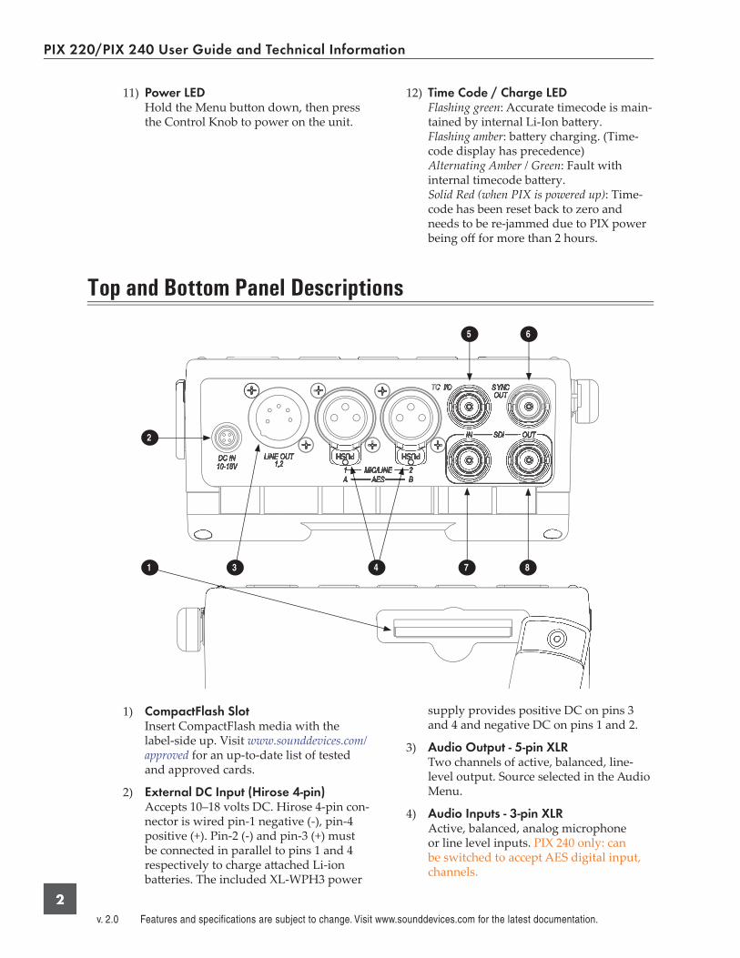
11) Power LEDHold the Menu butt on down, then press the Control Knob to power on the unit.
12) Time Code / Charge LEDFlashing green: Accurate timecode is main-tained by internal Li-Ion batt ery.Flashing amber: batt ery charging. (Time-code display has precedence)Alternating Amber / Green: Fault with internal timecode batt ery.Solid Red (when PIX is powered up): Time-code has been reset back to zero and needs to be re-jammed due to PIX power being off for more than 2 hours.
Top and Bottom Panel Descriptions
3
2
1 4 87
65
1) CompactFlash SlotInsert CompactFlash media with the label-side up. Visit www.sounddevices.com/approved for an up-to-date list of tested and approved cards.
2) External DC Input (Hirose 4-pin)Accepts 10–18 volts DC. Hirose 4-pin con-nector is wired pin-1 negative (-), pin-4 positive (+). Pin-2 (-) and pin-3 (+) must be connected in parallel to pins 1 and 4 respectively to charge att ached Li-ion batt eries. The included XL-WPH3 power
supply provides positive DC on pins 3 and 4 and negative DC on pins 1 and 2.
3) Audio Output - 5-pin XLRTwo channels of active, balanced, line-level output. Source selected in the Audio Menu.
4) Audio Inputs - 3-pin XLRActive, balanced, analog microphone or line level inputs. PIX 240 only: can be switched to accept AES digital input, channels.
PIX 220/PIX 240 User Guide and Technical Information
3
5) Timecode BNCSelectable timecode input or output. Con-fi gured with Video Timecode/Sync Timecode BNC menu item.
6) Sync Output BNCSelectable genlock or wordclock output. Confi gured with Setup Menu option Timecode/Sync Sync Out.
7) SDI Input BNCHD-SDI video input. Accepts SMPTE 292M (HD-SDI) signal with up to 8 chan-nels of embedded audio.
8) SDI Output BNCHD-SDI video output. Outputs SMPTE 292M (HD-SDI) signal with up to 8 chan-nels of embedded audio.
Right Panel Descriptions
3 4 5 7
621
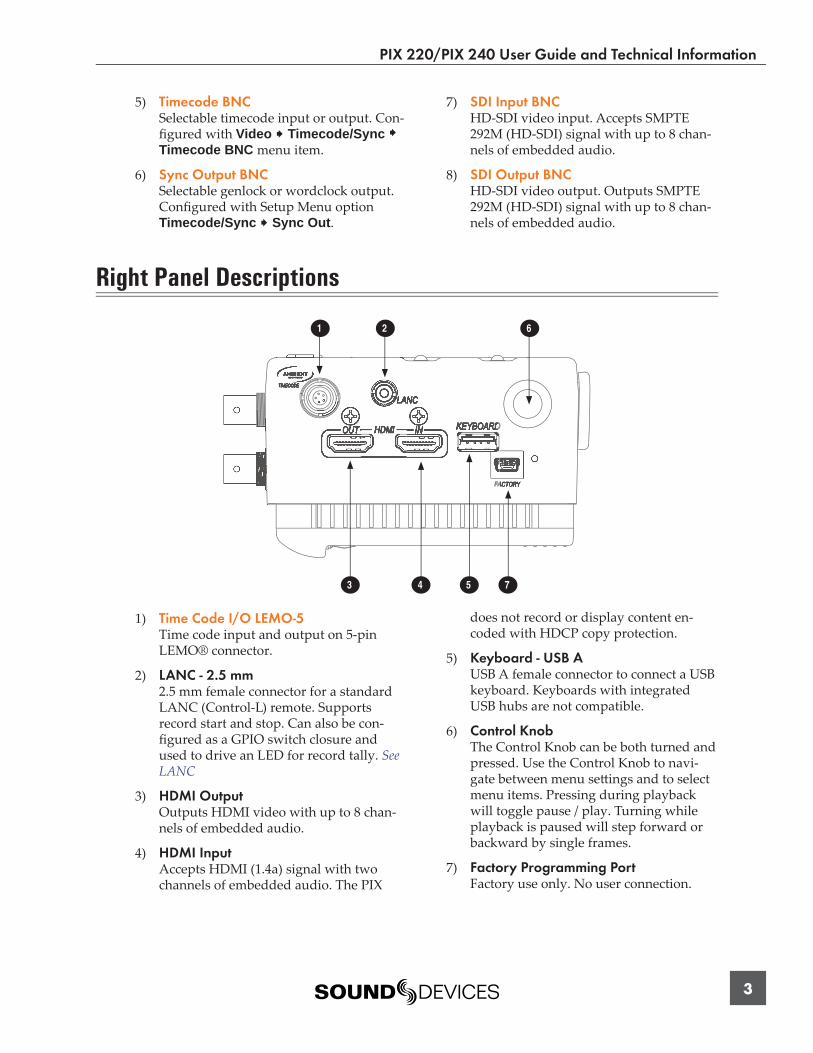
1) Time Code I/O LEMO-5Time code input and output on 5-pin LEMO® connector.
2) LANC - 2.5 mm2.5 mm female connector for a standard LANC (Control-L) remote. Supports record start and stop. Can also be con-fi gured as a GPIO switch closure and used to drive an LED for record tally. See LANC
3) HDMI OutputOutputs HDMI video with up to 8 chan-nels of embedded audio.
4) HDMI InputAccepts HDMI (1.4a) signal with two channels of embedded audio. The PIX
does not record or display content en-coded with HDCP copy protection.
5) Keyboard - USB AUSB A female connector to connect a USB keyboard. Keyboards with integrated USB hubs are not compatible.
6) Control KnobThe Control Knob can be both turned and pressed. Use the Control Knob to navi-gate between menu sett ings and to select menu items. Pressing during playback will toggle pause / play. Turning while playback is paused will step forward or backward by single frames.
7) Factory Programming PortFactory use only. No user connection.
PIX 220/PIX 240 User Guide and Technical Information
v. 2.0 Features and specifications are subject to change. Visit www.sounddevices.com for the latest documentation.
4
Left Panel Descriptions
321 4
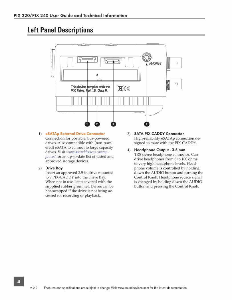
1) eSATAp External Drive ConnectorConnection for portable, bus-powered drives. Also compatible with (non-pow-ered) eSATA to connect to large capacity drives. Visit www.sounddevices.com/ap-proved for an up-to-date list of tested and approved storage devices.
2) Drive BayInsert an approved 2.5-in drive mounted to a PIX-CADDY into the Drive Bay. When not in use, keep covered with the supplied rubber grommet. Drives can be hot-swapped if the drive is not being ac-cessed for recording or playback.
3) SATA PIX-CADDY ConnectorHigh-reliability eSATAp connection de-signed to mate with the PIX-CADDY.
4) Headphone Output - 3.5 mmTRS stereo headphone connector. Can drive headphones from 8 to 100 ohms to very high headphone levels. Head-phone volume is controlled by holding down the AUDIO butt on and turning the Control Knob. Headphone source signal is changed by holding down the AUDIO Butt on and pressing the Control Knob.

PIX 220/PIX 240 User Guide and Technical Information
5
Rear Panel Descriptions
3 2
1
1) Battery MountsAccepts Sony® InfoLithium L-Series bat-teries. Also accepts third party batt eries compatible with the Sony mount.
2) FanWhisper-quiet, low-speed, single, large diameter fan. Runs continuously.
3) Mounting Point - ¼ - 20Stainless-steel threaded att achment point.

PIX 220/PIX 240 User Guide and Technical Information
v. 2.0 Features and specifications are subject to change. Visit www.sounddevices.com for the latest documentation.
6
PIX-CADDY (Optional)
The PIX-CADDY is a recommended accessory to record video fi les to approved 2.5” drives. When removed from a PIX 220 or PIX 240, PIX-CADDY operates as a high-speed drive interface to Mac OS and Windows computers.
3
2
1
5
6
4
1) FireWire 800FireWire 800 or 400 (backward compat-ible). Requires a powered FireWire 800 or 400 port.
2) eSATApHigh-speed data transfer over 5V eSATAp. Requires a 5V powered eSATAp port.
3) USB 3.0High-speed data transfer over USB 3.0 (backward compatible with USB 2.0).
4) 2.5” Drive SlotConnector for approved 2.5-inch SATA II (3.0 gb/s) drives. Sound Devices main-tains a list of tested and approved SSD drives for use with PIX video recorders. Visit www.sounddevices.com/approved for an up-to-date list of tested and approved drives.
5) Activity LEDIlluminates when recording, playing, reading, or writing to the att ached 2.5” drive. Do not remove the caddy while the Activity LED is illuminated. LED does not illuminate when connected to a computer’s eSATA port.
6) Release LatchesSecures the PIX-CADDY to the recorder. Press both latches to remove the caddy assembly.

PIX 220/PIX 240 User Guide and Technical Information
7
Powering
The PIX 220 and PIX 240 are powered from either removable, Li-ion rechargeable batt eries or ex-ternal DC. One or two removable 7.2 V Li-ion batt eries can be mounted to the recorder and used as either primary or backup power. The PIX automatically chooses the power source based on the voltage level of the external power supply. If the external voltage falls below the level of att ached Li-ion batt eries, the unit will transition to Li-ion power. The transition between external and removable batt ery powering is seamless and has no aff ect on recording or playback operation.
Removable Li-Ion Batteries PIX recorders are compatible with Sony L-Series Li-ion rechargeable batt eries. Several power capaci-ties are available in this batt ery type, ranging from 1000 mAh to 7000 mAh. Larger amp-hour batt er-ies provide more run-time.
One or two L-Series batt eries can be att ached to the rear panel. When two batt eries are att ached, they operate in parallel. A second batt ery increases run time and both batt eries will drain evenly. Batt eries can be hot-swapped for continuous recording.
When powered by the removable Li-ion batt ery the LCD displays the batt ery voltage of each batt ery. The nominal operating voltage for Li-ion batt eries is 7.2 V, with operating voltages ranging between 6.8–8.5 V. When the total voltage drops to 6.9 V, the voltage display on the LCD will begin fl ashing red and the power LED will also fl ash red to warn that the batt ery is nearly depleted. When the volt-age reaches 6.8 volts the recorder powers down—any recording in-process will automatically close (stop).
Li-Ion Battery Charging When power is supplied to the PIX recorder on pins 1, 2 (-), and pins 3, 4 (+) of the External DC Input and the PIX recorder is powered off , the recorder will charge att ached Li-ion batt eries. The included XL-WPH3 power supply will charge Li-ion batt eries when the recorder is powered down.
The optional XL-AB accessory cable can be used to power a PIX recorder from an Anton Bauer D-Tap connector. The XL-AB will not charge att ached Li-ion batt eries. Make certain that the Anton Bauer batt ery can supply enough power for both camera and the PIX recorder.
Menu and Navigation
Main ViewThe Main View displays the live or playback video and the On-screen Display. the Main View is the default view which appears when no other views or menus are selected.
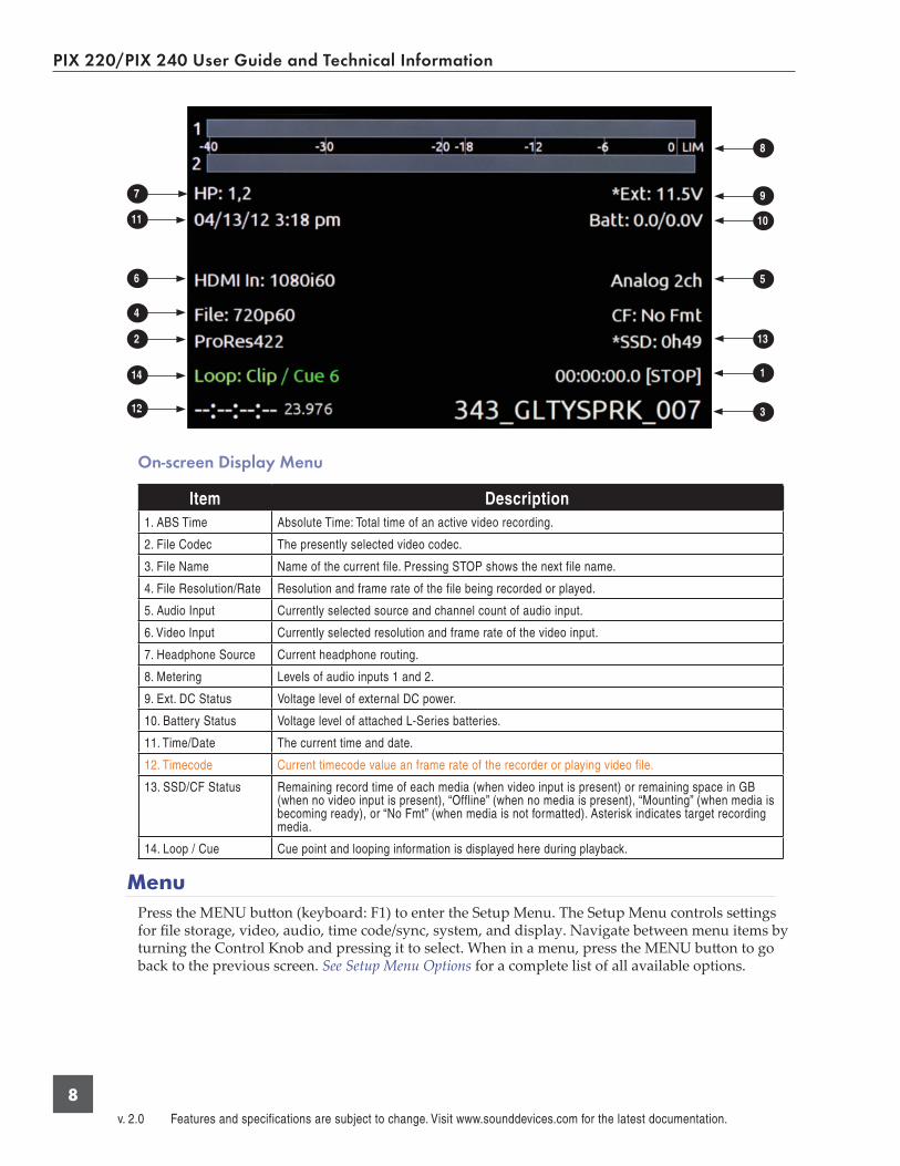
On-screen Display
The On-screen Display (OSD) provides information superimposed over the Main View. From the Main View, the LCD butt on will toggle the OSD on and off . Items included in the OSD are confi g-ured with the Setup Menu option Display. When factory sett ings are loaded from the Quick Setup menu item, all OSD items are shown.
PIX 220/PIX 240 User Guide and Technical Information
v. 2.0 Features and specifications are subject to change. Visit www.sounddevices.com for the latest documentation.
8
12
11
14
2
4
6
7
3
1
13
5
10
9
8
On-screen Display Menu
Item Description 1. ABS Time Absolute Time: Total time of an active video recording.
2. File Codec The presently selected video codec.
3. File Name Name of the current file. Pressing STOP shows the next file name.
4. File Resolution/Rate Resolution and frame rate of the file being recorded or played.
5. Audio Input Currently selected source and channel count of audio input.
6. Video Input Currently selected resolution and frame rate of the video input.
7. Headphone Source Current headphone routing.
8. Metering Levels of audio inputs 1 and 2.
9. Ext. DC Status Voltage level of external DC power.
10. Battery Status Voltage level of attached L-Series batteries.
11. Time/Date The current time and date.
12. Timecode Current timecode value an frame rate of the recorder or playing video file.
13. SSD/CF Status Remaining record time of each media (when video input is present) or remaining space in GB (when no video input is present), “Offline” (when no media is present), “Mounting” (when media is becoming ready), or “No Fmt” (when media is not formatted). Asterisk indicates target recording media.
14. Loop / Cue Cue point and looping information is displayed here during playback.
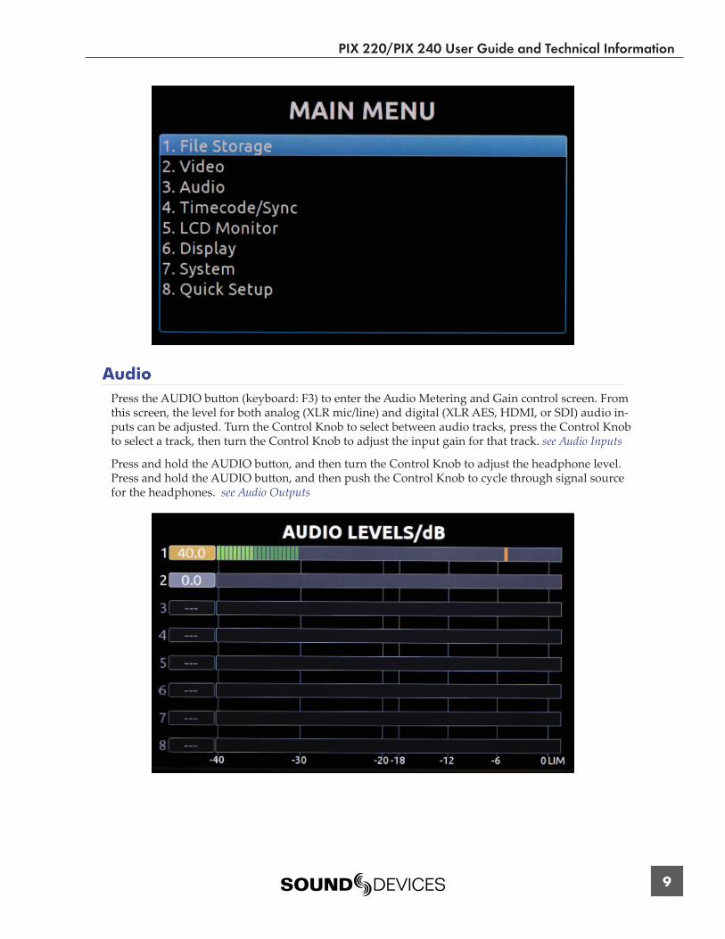
Menu Press the MENU butt on (keyboard: F1) to enter the Setup Menu. The Setup Menu controls sett ings for fi le storage, video, audio, time code/sync, system, and display. Navigate between menu items by turning the Control Knob and pressing it to select. When in a menu, press the MENU butt on to go back to the previous screen. See Setup Menu Options for a complete list of all available options.
PIX 220/PIX 240 User Guide and Technical Information
9
Audio Press the AUDIO butt on (keyboard: F3) to enter the Audio Metering and Gain control screen. From this screen, the level for both analog (XLR mic/line) and digital (XLR AES, HDMI, or SDI) audio in-puts can be adjusted. Turn the Control Knob to select between audio tracks, press the Control Knob to select a track, then turn the Control Knob to adjust the input gain for that track. see Audio Inputs
Press and hold the AUDIO butt on, and then turn the Control Knob to adjust the headphone level. Press and hold the AUDIO butt on, and then push the Control Knob to cycle through signal source for the headphones. see Audio Outputs
PIX 220/PIX 240 User Guide and Technical Information
v. 2.0 Features and specifications are subject to change. Visit www.sounddevices.com for the latest documentation.
10
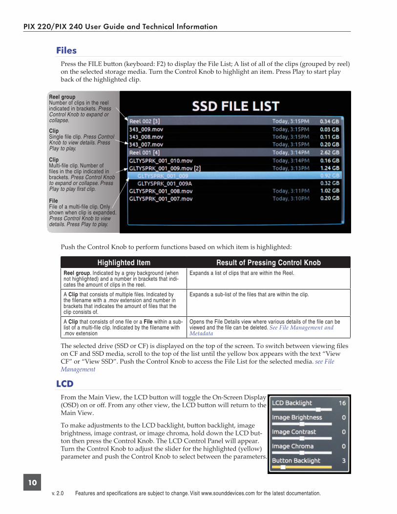
Files Press the FILE butt on (keyboard: F2) to display the File List; A list of all of the clips (grouped by reel) on the selected storage media. Turn the Control Knob to highlight an item. Press Play to start play back of the highlighted clip.
Reel groupNumber of clips in the reel indicated in brackets. Press Control Knob to expand or collapse.
ClipMulti-file clip. Number of files in the clip indicated in brackets. Press Control Knob to expand or collapse. Press Play to play first clip.
FileFile of a multi-file clip. Only shown when clip is expanded. Press Control Knob to view details. Press Play to play.
ClipSingle file clip. Press Control Knob to view details. Press Play to play.
Push the Control Knob to perform functions based on which item is highlighted:
Highlighted Item Result of Pressing Control KnobReel group. Indicated by a grey background (when not highlighted) and a number in brackets that indi-cates the amount of clips in the reel.
Expands a list of clips that are within the Reel.
A Clip that consists of multiple files. Indicated by the filename with a .mov extension and number in brackets that indicates the amount of files that the clip consists of.
Expands a sub-list of the files that are within the clip.
A Clip that consists of one file or a File within a sub-list of a multi-file clip. Indicated by the filename with .mov extension
Opens the File Details view where various details of the file can be viewed and the file can be deleted. See File Management and Metadata
The selected drive (SSD or CF) is displayed on the top of the screen. To switch between viewing fi les on CF and SSD media, scroll to the top of the list until the yellow box appears with the text “View CF” or “View SSD”. Push the Control Knob to access the File List for the selected media. see File Management
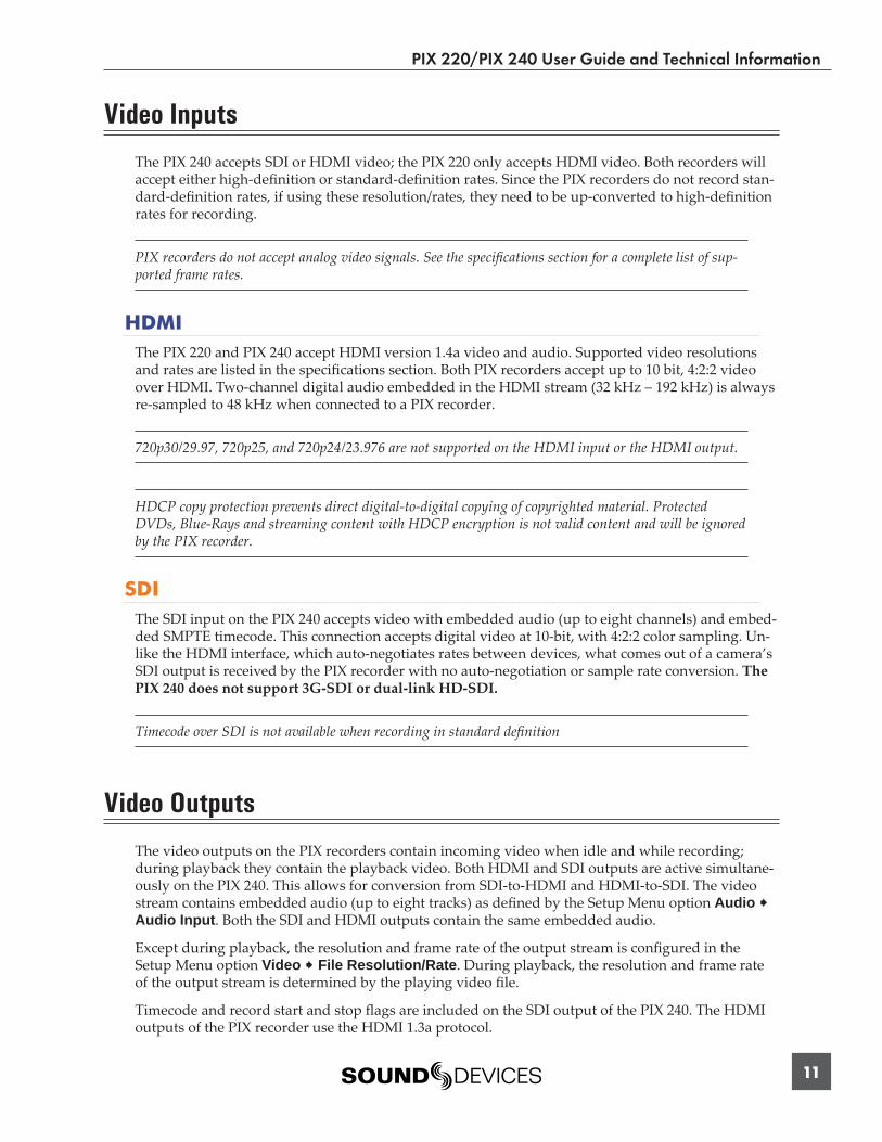
LCDFrom the Main View, the LCD butt on will toggle the On-Screen Display (OSD) on or off . From any other view, the LCD butt on will return to the Main View.
To make adjustments to the LCD backlight, butt on backlight, image brightness, image contrast, or image chroma, hold down the LCD but-ton then press the Control Knob. The LCD Control Panel will appear. Turn the Control Knob to adjust the slider for the highlighted (yellow) parameter and push the Control Knob to select between the parameters.
PIX 220/PIX 240 User Guide and Technical Information
11
Video Inputs
The PIX 240 accepts SDI or HDMI video; the PIX 220 only accepts HDMI video. Both recorders will accept either high-defi nition or standard-defi nition rates. Since the PIX recorders do not record stan-dard-defi nition rates, if using these resolution/rates, they need to be up-converted to high-defi nition rates for recording.
PIX recorders do not accept analog video signals. See the specifi cations section for a complete list of sup-ported frame rates.
HDMI The PIX 220 and PIX 240 accept HDMI version 1.4a video and audio. Supported video resolutions and rates are listed in the specifi cations section. Both PIX recorders accept up to 10 bit, 4:2:2 video over HDMI. Two-channel digital audio embedded in the HDMI stream (32 kHz – 192 kHz) is always re-sampled to 48 kHz when connected to a PIX recorder.
720p30/29.97, 720p25, and 720p24/23.976 are not supported on the HDMI input or the HDMI output.
HDCP copy protection prevents direct digital-to-digital copying of copyrighted material. Protected DVDs, Blue-Rays and streaming content with HDCP encryption is not valid content and will be ignored by the PIX recorder.
SDI The SDI input on the PIX 240 accepts video with embedded audio (up to eight channels) and embed-ded SMPTE timecode. This connection accepts digital video at 10-bit, with 4:2:2 color sampling. Un-like the HDMI interface, which auto-negotiates rates between devices, what comes out of a camera’s SDI output is received by the PIX recorder with no auto-negotiation or sample rate conversion. The PIX 240 does not support 3G-SDI or dual-link HD-SDI.
Timecode over SDI is not available when recording in standard defi nition
Video Outputs
The video outputs on the PIX recorders contain incoming video when idle and while recording; during playback they contain the playback video. Both HDMI and SDI outputs are active simultane-ously on the PIX 240. This allows for conversion from SDI-to-HDMI and HDMI-to-SDI. The video stream contains embedded audio (up to eight tracks) as defi ned by the Setup Menu option Audio Audio Input. Both the SDI and HDMI outputs contain the same embedded audio.
Except during playback, the resolution and frame rate of the output stream is confi gured in the Setup Menu option Video File Resolution/Rate. During playback, the resolution and frame rate of the output stream is determined by the playing video fi le.
Timecode and record start and stop fl ags are included on the SDI output of the PIX 240. The HDMI outputs of the PIX recorder use the HDMI 1.3a protocol.
PIX 220/PIX 240 User Guide and Technical Information
v. 2.0 Features and specifications are subject to change. Visit www.sounddevices.com for the latest documentation.
12
Audio Inputs
The PIX recorders accept either two analog audio inputs on XLR connectors or two channels of embedded audio on the HDMI input. The PIX 240 also accepts up to 8 channels of embedded audio on the SDI input and the analog XLR inputs can be switched to accept four channels (two streams) of AES/EBU digital audio.
Analog Audio InputsPIX recorders have two high-performance analog audio inputs. These balanced inputs accept either mic- or line-level signals, and include high-pass fi lters, limiters, 48V phantom power, linking, and M/S matrixing.
Input Low-cut Filters
Setup Menu options: Audio Analog 1 Low cut and Audio Analog 2 Low cut.
Low-cut fi lters on analog inputs reduce sensitivity to low frequency signals (such as wind noise from a microphone). Signals below the selected frequency are att enuated. The amount of att enuation increases at lower frequencies according to the slope of the low-cut fi lter. The Setup Menu option Audio Low cut Slope allows adjustment of the slope for both analog inputs.
Input Limiters
Setup Menu option: Audio Input Limiter (1,2).
Analog inputs incorporate an advanced, analog/DSP-controlled hybrid limiter to prevent input over-load. In normal operation and with proper gain sett ings, the limiters should rarely engage. When activated, limiters prevent unusually high input signal levels from overloading the analog input stage of the preamp.
Limiting activity is indicated by a yellow segment on the right side of the audio meters (both in the Audio View and the Main View). When the yellow segment is visible, limiting is occurring. The Input Limiters are active for both mic- and line-level inputs. When inputs are linked, the limiters are linked.
Input Polarity
Setup Menu options: Audio Analog 1 Polarity and Audio Analog 2 Polarity.
Input Polarity inversion (sometimes referred as phase reverse) can be applied to either analog input. This can be used to rectify incorrectly wired balanced cables, to prevent signal cancellation when a source is dual-miked from opposite directions, or reverse left/right with MS microphone confi gurations.
Digital Audio InputsThe PIX 220 and PIX 240 accept digital audio from HDMI, SDI (PIX 240 only), and AES/EBU (PIX 240 only) inputs. All audio is sampled at 48 kHz.
HDMI / SDI Embedded Audio
The PIX 220 and PIX 240 accept two channels of embedded digital audio on the HDMI Video Input. The PIX 240 accepts up to 8 channels of digital audio on its SDI input.

PIX 220/PIX 240 User Guide and Technical Information
13
AES3
The PIX 240 accepts AES3 (AES/EBU) digital signals with sampling rates from 32 kHz up to 192 kHz and bit depths up to 24-bits. Files recorded by the PIX 240 are uncompressed 24 bit, with sampling rates of 48 kHz. All digital signals connected to PIX are sampling rate converted to 48 kHz, including signals sent at 48 kHz.
Input Linking
Setup Menu option: Audio Input Linking
Inputs 1-2 can be linked together so that a gain adjustment to one channel will also aff ect the other (see Input Level Control). When inputs 1-2 are linked, the limiters are also linked. 48V phantom power, analog low-cut, and analog polarity sett ings are set independently for each channel, even when inputs are linked.
Linked inputs are useful when the PIX is receiving a left/right stereo signal on inputs 1 and 2. Ex-amples include stereo program from an external mixer, stereo program from a camera, and micro-phones oriented in a stereo confi guration.
M/S Matrixing
Mid-side (MS) matrixing is a method for processing audio signal from a cardioid microphone and a bidirectional microphone into a stereo signal. The cardioid microphone is the “mid” signal and con-nects to input 1, and the bidirectional microphone is the “side” signal and connects to input 2. The cardioid microphone is pointed at the sound source, and the bidirectional microphone is oriented sideways (positioned with its capsule as near as possible to the cardioid microphone’s capsule). the following diagram shows the relative polar patt erns of microphones in an M/S confi guration.
Mid Signal
Side Signal
To produce a stereo signal from an M/S confi guration, the signal from both microphones must be processed. The PIX recorder can perform this processing on inputs 1 and 2 when Setup Menu option Audio Input Linking is set to 1-2MS.
Choosing Audio SourcesThe PIX recorders are capable of recording audio from the two analog audio inputs or digital sources (AES3 or video input). The Setup Menu option Audio Audio Input provides the following options for audio sources:

PIX 220/PIX 240 User Guide and Technical Information
v. 2.0 Features and specifications are subject to change. Visit www.sounddevices.com for the latest documentation.
14
Audio Source Tracks on Recorded Files and Video OutputsAnalog XLR 1: Analog Input XLR 1
2: Analog Input XLR 2
AES (Digital) XLR 1-2ch 1: Channel 1, AES XLR A2: Channel 2, AES XLR A
AES (Digital) XLR 1-4ch 1: Channel 1, AES XLR A2: Channel 2, AES XLR A
3: Channel 1, AES XLR B4: Channel 2, AES XLR B
SDI/HDMI 2ch 1: Channel 1, HDMI/SDI video input2: Channel 2, HDMI/SDI video input
SDI 4ch 1: Channel 1, SDI video input2: Channel 2, SDI video input
3: Channel 3, SDI video input4: Channel 4, SDI video input
SDI 6ch 1: Channel 1, SDI video input2: Channel 2, SDI video input3: Channel 3, SDI video input
4: Channel 4, SDI video input5: Channel 5, SDI video input6: Channel 6, SDI video input
SDI 8ch 1: Channel 1, SDI video input2: Channel 2, SDI video input3: Channel 3, SDI video input4: Channel 4, SDI video input
5: Channel 5, SDI video input6: Channel 6, SDI video input7: Channel 7, SDI video input8: Channel 8, SDI video input
Analog 2ch +SDI/HDMI 2ch 1: Analog Input XLR 12: Analog input XLR 2
3: Channel 1, HDMI/SDI video input4: Channel 2, HDMI/SDI video input
Analog 2ch +SDI 4ch 1: Analog Input XLR 12: Analog Input XLR 23: Channel 1, SDI video input
4: Channel 2, SDI video input5: Channel 3, SDI video input6: Channel 4, SDI video input
Analog 2ch +SDI 6ch 1: Analog Input XLR 12: Analog Input XLR 23: Channel 1, SDI video input4: Channel 2, SDI video input
5: Channel 3, SDI video input6: Channel 4, SDI video input7: Channel 5, SDI video input8: Channel 6, SDI video input
OFF None
The selected audio source is included in the HDMI and SDI streams on the Video Outputs of the PIX recorder. See Audio Outputs
Input Level Control Input audio gain is adjusted with the Control Knob when in the Audio Menu. The Audio Menu is ac-cessed by pushing the AUDIO Butt on. The audio channel highlighted yellow is controllable. Turning the Control Knob highlights a diff erent audio input. To adjust the gain of an audio input:
1. Highlight the audio input.

PIX 220/PIX 240 User Guide and Technical Information
15
2. Push the Control Knob to enter gain adjustment mode (indicated by a blue highlight)
3. Turn the Control Knob to adjust the gain value up or down. This adjustment will aff ect gain in real-time.
4. Push the Control Knob to exit the gain control fi eld.
Audio Outputs
Analog 5-Pin XLR OutputThe two analog outputs of the PIX recorder are active-balanced, line-level outputs (+18dBu max) on a single, 5-pin XLR connection. At factory default, the source of the analog Outputs is 1 and 2. This can be adjusted in the Setup Menu: Audio Output Source - XLR. The output level of each output can be att enuated (down to -20 dB) in the setup menu: Audio Output XLR 1 Attenuation and Audio Output XLR 2 Attenuation.
Embedded Audio on HDMI and SDI The Setup Menu parameter Audio Audio Input determines what signal is present on the HDMI and SDI output. This allows for replacement of audio coming in from a camera with audio connected to the recorder.
Headphone Output
The PIX recorder is capable of driving headphones to extremely high sound pressure levels. Hearing experts advise against exposure to high sound pressure levels for extended periods.
The PIX recorder’s headphone output is a fl exible tool for monitoring audio in the fi eld. The head-phone level can be adjusted while in the Main View by pressing and holding the Audio butt on while turning the Control Knob.
To quickly select amongst headphone sources, Press and hold the Audio butt on an press the Control Knob to step through headphone source options. The Headphone Source can also be selected in the Setup Menu option Audio Headphone Source.

PIX 220/PIX 240 User Guide and Technical Information
v. 2.0 Features and specifications are subject to change. Visit www.sounddevices.com for the latest documentation.
16
LCD A/V Alignment
Audio signal is routed to the headphones in real-time. The video displayed on the LCD is delayed slightly. When the Setup Menu option Audio Headphone: LCD A/V Align is set to On, the audio signal to the headphones will be delayed slightly to align with the video displayed on the LCD.
Video Monitoring Features
The PIX recorders include various monitoring features to assist the camera operator during shooting. These functions only aff ect signal on the LCD display and will never aff ect the recorded video or the video signal sent to the PIX recorder’s outputs.
Exposure Assist
LCD + FILES
Exposure assist features mark areas of the video image based on the exposure level. With over- or under-exposed areas of the image clearly marked, adjustments can be made on the camera to ensure that the signal reaching the recorder has a proper exposure. Exposure Assist is enabled by holding down the LCD butt on and pressing the FILES butt on. When Exposure Assist is enabled, “EXP” is displayed on the OSD in yellow text.
When exposure assist is enabled, False Color or Zebra stripes will be overlaid on the LCD monitor signal. The Setup Menu option LCD Monitor Exposure Assist determines which mode will acti-vate when exposure assist is toggled on.
The following image is a luminance ramp signal displayed on a PIX recorder with no exposure assist enabled. Screen shots in the following sections show the eff ect of the various Exposure Assist fea-tures on this test signal.

PIX 220/PIX 240 User Guide and Technical Information
17
False Color
False Color exposure assist mode replaces pixels with a specifi c color relative to the luminance level. The two types of False Color (selectable from Setup Menu option LCD Monitor Exposure Assist) are 12-step and 4-step.
12-step False Color mode divides the monitor signal into 12 luminance ranges and assigns a color to each. 12-step
100-108 Red95-99 Orange85-94 Yellow79-84 Light Yellow59-78 Light Grey53-58 Pink49-52 Medium Grey43-48 Green23-42 Dark Grey13-22 Light Blue3-12 Blue0-2 White
4-step False Color mode divides the monitor signal into 4 ranges and assigns a color to all but one range (this range is displayed without chroma). The table below illustrates the colors as they relate to luminance levels (IRE).
4-step101+ Red99-100 Orange3-98 N/A0-2 Blue

PIX 220/PIX 240 User Guide and Technical Information
v. 2.0 Features and specifications are subject to change. Visit www.sounddevices.com for the latest documentation.
18
Zebras
Zebra stripe exposure assist mode overlays diagonal stripes over areas that are in a defi ned lumi-nance range (Zebra 1) or above a defi ned luminance threshold (Zebra 2). The range for Zebra 1 is 5% above and below the IRE value of Setup Menu option LCD Monitor Zebra 1 Level. The range for Zebra 2 is everything above the IRE value of Setup Menu option LCD Monitor Zebra 2 Thresh-old. The options for Zebra display (selectable from Setup Menu option LCD Monitor Exposure Assist) are Zebra 1, Zebra 2, or both Zebra 1 and Zebra 2 simultaneously.
Zebra 185 IRE
Zebra 270 IRE (+/- 5%)
Focus Assist
LCD + MENU
Focus Assist features mark sharp edges in the video image to assist in focusing on the desired sub-ject. Focus assist is enabled by holding down the LCD butt on and pressing the MENU butt on. The word “FOCUS” is displayed in yellow text on the OSD when Focus Assist is enabled. There are two available Focus Assist modes: Peaking and Edge Enhance.
Peaking
Peaking fi nds sharp edges in a video (based on luminance) and replaces pixels in those areas to high-light the edges.
The Setup Menu option LCD Monitor Peaking Sensitivity sets what level of sharpness will be marked by the Peaking fi lter. A sett ing of High will mark only the sharpest areas of the image, while a sett ing of Low will also mark areas that are not as sharp.
The Setup Menu option LCD Monitor Peaking Background Contrast is used to adjust the area of the video image that is not highlighted while Peaking is enabled.

PIX 220/PIX 240 User Guide and Technical Information
19
The color of the Peaking marks can be set with the Setup Menu option LCD Monitor Peaking Color.
The following image comparison demonstrates the eff ect of Peaking on an image with a shallow depth-of-fi eld and a short focal length (top) and a longer focal length (bott om).
Edge Enhance
The Edge Enhance fi lter uses an algorithm which enhances the variation of the luminance of all edges present in the video image. The following image comparison demonstrates the eff ect of Edge Enhance on an image with a shallow depth-of-fi eld and a short focal length (top) and a longer focal length (bott om).

PIX 220/PIX 240 User Guide and Technical Information
v. 2.0 Features and specifications are subject to change. Visit www.sounddevices.com for the latest documentation.
20
Zoom
LCD + AUDIO
The Zoom function enlarges the video image to a 1:1 pixel ratio. To toggle Zoom on and off , hold down the LCD butt on and press the AUDIO butt on. When Zoom is enabled, “ZOOM” is displayed on the OSD in yellow text and all other OSD elements are hidden. When zoomed, turning the rotary encoder moves vertically and REW and FF butt ons move left and right respectively.
FlipSome mounting situations require the PIX recorder to be upside-down. The LCD output can be verti-cally inverted to facilitate upside-down operation with the Setup Menu option LCD Monitor Flip Display.
Recording
With a valid video signal present at the input, pushing the REC butt on will start recording. While recording, the REC butt on will illuminate red and the OSD Items Timecode, File Name, and ABS time turn red. The PIX recorder is a record-priority device and will enter record any time the REC butt on is pressed, except when playback is occurring (playback must be stopped before a recording can begin).
While recording, the FF, RW, Play, and FILES butt ons are disabled. Push the Stop butt on to stop the recording. During both recording and playback, the MENU and FILES butt ons are locked out. When the Setup Menu option System REC button File Split is set to On, pushing the REC butt on during recording will begin a new fi le. When the recording exceeds the time set in Setup Menu option System File Split every, a new fi le will be created and grouped with the other fi les from the clip in the File View (see File Management and Metadata).
To discard the last take and delete the fi le (False take), hold down the Stop butt on and push the Rewind butt on. A dialog will appear warning that the last take will be deleted and indicating the fi le name. Use the Control Knob to highlight OK and push the Control Knob to confi rm.
PIX 220/PIX 240 User Guide and Technical Information
21
Selecting File Resolution and Frame RateThe PIX recorders can record video in numerous resolutions and frame rates. The Setup Menu op-tion Video File Resolution/Rate sets the resolution and frame rate of recorded Quicktime fi les. This Setup Menu option also determines the resolution and frame rate of the live HDMI and SDI outputs signals, except during playback. The PIX recorder can record Quicktime fi les in the follow-ing resolutions and frame rates:
• 1080 p30• 1080 p29.97• 1080 p25• 1080 p24• 1080 p23.976• 1080 i60• 1080 i59.94• 1080 i50
• 1080 PsF 30• 1080 PsF 29.97• 1080 PsF 25• 1080 PsF 24• 1080 PsF 23.976• 720 p60• 720 p59.94• 720 p50
• 720 p30• 720 p29.97• 720 p25• 720 p24• 720 p23.976• 576i50 *• 480i59.94 *
When Setup Menu option Video File Resolution/Rate is set to Same as Video Input, recorded Quicktime fi les and HDMI and SDI output signals will be of the same resolution and frame rate as the input video signal.
* Standard defi nition recording is only available for ProRes 422 HQ, ProRes 422, and ProRes 422 Proxy.
Progressive Segmented Frames (PsF)
Some cameras output video signal in progressive segmented frames (PsF). PsF is a method for transmitt ing progressive video in an interlaced stream. A device generates PsF signal by splitt ing each frame into two segments. PsF segments are the same as interlaced fi elds in that one segment represents the even lines of a frame and the other segment represents the odd lines of a frame. PsF segments diff er from interlaced fi elds in that there is no motion between each segment in a pair.
The PIX will automatically sense PsF signal from most cameras that output PsF over SDI. This is accomplished through the use a fl ag inserted into the SDI signal by the camera. If a camera does not insert this fl ag into the SDI stream or if it outputs PsF signal over HDMI, then the PIX sett ing Video
Input PsF Detect can be set to Interpret 1080i as PsF. This will force the PIX to treat all 1080i signal as if it were PsF and deinterlace it accordingly.
Selecting a Video Codec Setup Menu option: Video Codec.
PIX has two families of intra-frame, DCT based codecs available: Apple ProRes and Avid DNxHD, with four levels of data compression available for each. Both codecs are intermediate codecs that assist the editing process by eliminating the need to transcode video before importing into Final Cut (ProRes) or Avid (ProRes or DNxHD).
ProRes is a variable data rate codec; DNxHD is a fi xed data rate codec. PIX recorders support all compression levels and bit rates of DNxHD and ProRes and automatically record the correct bit rate dependent upon the video input resolutions and frame rate. The data rates indicated in the Setup Menu item Video Codec indicate the maximum data rate at 1080p30.
DNxHD 36 Mb/s only supports 1080p signal. Standard defi nition recording is only available for ProRes 422 HQ, ProRes 422, and ProRes 422 Proxy.

PIX 220/PIX 240 User Guide and Technical Information
v. 2.0 Features and specifications are subject to change. Visit www.sounddevices.com for the latest documentation.
22
Interruption of Signal During RecordingIn the event that video signal is lost (an unplugged HDMI or SDI cable, for example) during record-ing, the PIX recorder will pause the recording and wait for video signal to be re-initialized. If video signal is re-initialized within 10 seconds, the PIX recorder will begin recording again to a new fi le of the same name with an “A” appended to the end. Further interruptions of signal during that take will cause an alphabetic fi lename progression (“B”, “C”, etc).
Alignment of Audio and VideoAn advantage to recording audio on the PIX recorders along with the video is the elimination of audio/video sync problems in post. The PIX recorders have many options regarding audio sources along with the two options for video inputs, HDMI and SDI. Given this fl exibility, care must still be taken to ensure good audio/video sync.
If recording camera audio embedded on HDMI or SDI, then the audio/video alignment will be excel-lent provided the alignment is proper on the camera.
If recording audio using the PIX analog inputs or AES inputs, then a delay may need to be dialed in. The reason for this is that some cameras have a delay of one or more frames from lens to SDI/HDMI output. The PIX recorder on the other hand has no appreciable delay between audio (analog or AES input) an video (SDI/HDMI input). This means that if the camera does have this delay, the audio will lead the video as recorded by the PIX recorder. This delay can be adjusted via the Audio, Input 1 Delay and Input 2 Delay menus. Note that on some cameras, the lens-to-SDI/HDMI delay changes with resolution/frame rate. The best practice is to test the audio/video sync using sticks on a test fi le for each camera resolution/frame rate to be used on a project before starting.
Video Scaling and Frame Rate Conversion
PIX recorders feature powerful, hardware-based video scaling, frame rate conversion, and de-inter-lacing. This allows for converting the resolution and frame rate of video input to the recorded fi le and to the HDMI and SDI outputs in real-time.
Video scaling and/or de-interlacing is active whenever the Setup Menu option Video File Resolu-tion/Rate is set to something other than Same as Video Input. Any input signal can be converted to any resolution. When set to record progressive frames, the PIX recorders will convert incoming interlaced video to progressive frame video via its built-in, powerful, hardware-based de-interlacer. The PIX recorders will also convert progressive segmented frame (PsF) video to progressive video automatically if a progressive fi le (for instance 1080p30) is selected in Video File Resolution/Rate (If an interlaced fi le is selected, the PIX recorder will record PsF signal unaltered, but the fi le will be stamped as interlaced).
Frame rate conversion occurs whenever the frame rate of Video File Resolution/Rate diff ers from the frame rate of the input video signal. Frame rate conversion is achieved by appropriately dupli-cating or dropping frames. The PIX recorder will auto-sense between integer and non-integer frame rates (for instance 30 frames vs. 29.97 frames). The PIX will not frame rate convert between integer and non-integer values. For example, if the incoming video signal is 1080i59.94, it can be converted to 1080p29.97 or 720p59.94 but not 1080p30 or 720p60. The Setup Menu option Video File Reso-lution/Rate contains entries with a combination of integer and non-integer frame rates (such as 1080p30/29.97). When any of these options are selected, the PIX recorder will record in the indicated integer frame rate if the input video is an integer frame or record in the indicated non-integer frame rate if the input video is a non-integer frame rate.

PIX 220/PIX 240 User Guide and Technical Information
23
Not all frame rate conversions are visually desirable. When the OSD Item File Resolution/Rate is red, the conversion of the frame rate of the input video to the frame set by Video File Resolution/Rate will contain a fi nite amount of motion judder. For example, if the incoming video is 720p60 and Video File Resolution/Rate is set to 720p50, the cadence of dropped frames may be noticeable depending on the content. Conversions which are simply 1:2 or 2:1 (such as 1080i59.94 to 1080p29.97) introduce no motion judder. For these conversions, the OSD Item File Resolution/Rate stays white.
When the input video signal is 720p24 or 720p23.976, up-, down-, and cross-conversion is not available.
3:2 Pulldown Removal
Many cameras which shoot with a shutt er speed of 24/23.976 frames per second will output signal on the HDMI or SDI output at 60i/59.94i. To achieve this, the camera performs a “3:2 pulldown” pro-cess. The 3:2 pulldown process splits each frame into 2 fi elds and duplicates a fi eld periodically. The PIX recorders are capable of removing 3:2 pulldown from a 60i/59.94i signal and converting it back to 24/23.976 progressive frames per second in real-time. The PIX 3:2 removal process actively views video fi elds looking for duplicates. When these duplicates are sensed, then this cadence is locked in and the appropriate extra fi elds are removed. The process depends on motion in the incoming video. The OSD File Resolution/Rate changes from orange to white when this cadence is detected:
Orange: No 3:2 pulldown sensed in 60i/59.94i input signal. In-put video is being converted to 24p/23.976p using a conversion process which drops frames and may introduce judder.
White: 3:2 pulldown sensed in 60i/59.94i input video signal. Input video signal is being converted to 24p/23.976p using 3:2 pulldown removal which recreates 24p/23.976p as it is cap-tured from the camera’s shutt er.
Playback
The PIX recorder can play back any Quicktime fi le that it records. Playback is shown on the onboard LCD display and appears at both HDMI and SDI outputs. The PIX recorder will use a connected vid-eo source’s clock for its playback clock. If no video source is present, PIX will use its built-in clock. The PIX recorder will always play the last recorded fi le when the Play ( ) butt on is pressed from the Main View. In the File View, pressing the Play ( ) butt on will play the currently selected fi le. Push the Stop ( ) butt on anytime to stop playback and exit Playback Mode.
Playback ModePlaying a fi le enters Normal Playback Mode; The Play ( ) butt on and the OSD Items ABS Time, Timecode, and Filename will be green to indicate this. Press the Play ( ) butt on again during play-back to pause playback (The Play butt on will fl ash green). Turn the Control Knob while playback is paused to move forward or backward in single frame increments.

PIX 220/PIX 240 User Guide and Technical Information
v. 2.0 Features and specifications are subject to change. Visit www.sounddevices.com for the latest documentation.
24
Fast Forward and Rewind
Hold down the Fast Forward (>>) or Rewind (<<) butt on during playback for 2x (double) speed playback. When the Fast Forward (>>) or Rewind (<<) butt on is held down for more than 5 seconds, playback will become 8x speed. Normal playback will resume when Fast Forward (>>) or Rewind (<<) is released.
File Skip
A single push of the Fast Forward (>>) butt on during playback will begin playback of the next clip (if it exists). A single push of the Rewind (<<) butt on during playback will skip to the beginning of the currently playing fi le. If the Rewind (<<) butt on is pushed again immediately after it was pushed, playback will skip to the beginning of the previous clip (if it exists). File Skip functions will work while a clip playing and while it is paused.
Shuttle ModeThe PIX recorder is capable of various playback rates as well as reverse playback. These playback features are accessible from Shutt le Mode. Push the Control Knob while in Normal Playback Mode (playing or paused) to switch to Shutt le Mode in FFx1/2 mode. The OSD Items ABS Time, Time-code, and Filename will be blue to indicate Shutt le Mode. Turn the Control Knob to select among the available playback directions and rates. The following table defi nes the playback directions and speeds available when turning the Control Knob in Shutt le Mode.
Reverse Forward8 7 6 5 4 3 2 1 1/2 1/3 1/4 1/5 1/6 1/7 1/8 1/8 1/7 1/6 1/5 1/4 1/3 1/2 1 2 3 4 5 6 7 8
In Shutt le Mode, the playback direction and speed will be indicated on the LCD if Display ABS Time is set to On. The Fast Forward (>>) and Rewind (<<) butt ons will illuminate independently to indicate the playback direction. Push the Control Knob while in Shutt le Mode to pause playback. Push the Play ( ) butt on while in Shutt le Mode to return to Normal Playback Mode.
Cue PointsDuring Playback or Shutt le mode, pressing the FILES butt on will set a cue point. The previous cue point is always displayed with green text in the lower left-hand corner of the OSD. To quickly jump to the next or previous cue point, tap the Fast Forward (>>) butt on or Rewind (<<) butt on respectively.
LoopingLooping playback can be enabled between consecutive cue points or the beginning and end of the current clip. To toggle Looping Mode and begin looping the currently playing clip, hold the Play ( ) butt on for 1 second during Shutt le Mode or Playback Mode. “Loop: Clip” will be displayed with green text in the bott om left-hand corner of the OSD.
To loop between two consecutive cue points, hold down the Play ( ) butt on and press the Fast Forward (>>) butt on while playback is in between the two cue points. The two points that are being looped between will be displayed in green text in the bott om left-hand corner of the OSD. To return to looping the entire clip, hold down the Play ( ) butt on and press the Rewind (<<) butt on.
To exit Looping mode, hold down the Play ( ) butt on for 1 second.
Looping between cue points
Looping entire clip

PIX 220/PIX 240 User Guide and Technical Information
25
Playing Back Files on a Computer Video fi les recorded with the Apple ProRes codec require Quicktime to be installed. Quicktime can be downloaded from htt p://www.apple.com/quicktime/download/. See htt p://software.sounddevices.com/Apple_ProRes_White_Paper_July_2009.pdf for more detailed information about the ProRes codec.
Video fi les recorded with the Avid DNxHD codec require DNxHD drivers to be installed. Visit htt p://www.avid.com/dnxhd to download DNxHD drivers and for more detailed information about the DNxHD codec.
Synchronization and Timecode
This section gives a concise overview of timecode and video synchronization. This information ap-plies primarily to the PIX 240 and its advanced timecode and synchronization options; however it is useful information for PIX 220 and PIX 240 users alike. For information about the PIX 220’s timecode capabilities see PIX 220 Timecode Features
Synchronization of video, audio, and associated timecode while recording video and audio has long been a problematic area. Situations where several cameras are used can complicate issues further. There may be sync issues between two (or more) cameras and/or between audio recorders because of a) off set and b) drift. In a production environment (during recording), off set and drift are both terms to describe a timing problem between the timecode signal from two or more audio or video record-ers. In a post-production environment (a non-linear editor application), off set and drift are both terms to describe a timing problem between two or more audio or video fi les.
Off set (matching the beginning or “head” of a take) occurs because the beginning of takes are not aligned due to the absence or misuse of timecode. Drift (matching the end or “tail” of a take) oc-curs because diff erent recorders (audio or camera) run at diff erent rates - the beginning of fi les from each may have zero off set, but by the end they drift apart. The PIX recorders were designed with these problems in mind and include the most comprehensive and powerful synchronization features available in a portable recorder. These features can be used to alleviate or eliminate off set and drift problems in both production and post-production. While the PIX recorder’s design makes sett ing the parameters as easy as possible, a good understanding of synchronization is still necessary to prop-erly operate the PIX recorder and ensure a trouble-free workfl ow.
In a camera, the shutt er, video circuitry, audio sampling, and timecode all run off of one ‘heartbeat’ from its master internal clock. If this master clock is slightly fast, then the shutt er, audio sampling, and timecode will be slightly fast, and if the master clock is a slightly slow, the shutt er etc will be a bit slightly slow also.
When a PIX recorder’s video input is connected via HDMI or SDI to the camera, this heartbeat is passed through the HDMI or SDI, and the PIX is synchronized to the camera’s internal clock as well. The PIX video and audio circuitry is clocked off of this incoming video. The PIX recorder writes fi les based on this clock as well - each audio sample and video frame writt en out to the fi le is synchro-nized to the incoming video. This way, the PIX recorder is always completely in sync with the con-nected camera - there can never be any drift of audio or video between the camera and the PIX.
Drift problems in a workfl ow can arise when more than one camera is used on a shoot, as each camera is driven off of its own internal master clock. Since internal master clock speed will always vary from camera to camera (and vary based on temperature and time), each camera used will run at a slightly diff erent shutt er speed, audio sample rate and timecode rate. This is also true when recording video on a camera and recording audio on a separate recorder, as each device has its own internal master clock. Particularly problematic are long takes where there may be signifi cant drift
PIX 220/PIX 240 User Guide and Technical Information
v. 2.0 Features and specifications are subject to change. Visit www.sounddevices.com for the latest documentation.
26
from camera to camera from the beginning to end of the take’s fi le. Even if the heads match, the tails of a take may not.
These drift problems can be mitigated during recording by using a Genlock (or “Sync”) Input on a camera which takes over the camera’s internal master clock. Wiring several cameras’ Genlock Inputs together forces all of the cameras to run at the exact same rate with no drift. This same concept ap-plies to audio recorders using the Word Clock input. Genlock inputs are available only on higher-end cameras and Word Clock inputs are available on higher-end audio recorders.
Off set problems are easier to overcome than drift problems. By feeding each recording device with the same timecode signal, the fi les from diff erent recording devices can all be in sync and there will be no off set in post-production.
The PIX 240 can address the synchronization issues of both off set and drift (heads and tails) via its built-in Ambient® Lockit with Genlock Out and Timecode Reader. The PIX 240’s Ambient® Lockit features an internal clock which has an accuracy of +/-0.2ppm (½ frame per 24 hours). Numerous PIX 240 recorders can be used to maintain extremely tight synchronization.
Timecode ReaderThe PIX 240 includes a timecode reader which can accept incoming SMPTE timecode. The PIX 240 can read timecode from embedded SDI / HDMI, linear timecode fed into the “TC I/O” BNC con-nector, or the 5-pin LEMO® connector. The timecode reader is enabled whenever the Setup Menu option Timecode/Sync Timecode Mode is set to Ext TC (LTC) or Ext TC (SDI, HDMI), which indicates that it will read external timecode.
Timecode Reader operation is useful for simple cases where the PIX 240’s timecode follows the cam-era timecode. The timecode/sync of the PIX 240’s fi le will match exactly with the camera’s fi le with zero-drift.
In situations where a consistent off set is observed between PIX 240 fi les and other production record-ings, the PIX 240 can off set the timecode stamp. The Setup Menu option Timecode/Sync File Start TC Offset allows the user to adjust the frame off set from -10 to +10 in increments of 1. This sett ing does not aff ect timecode on the PIX 240’s outputs.
For shoots involving more than one camera or an audio recorder, using the PIX 240’s Timecode Gen-erator can be more benefi cial than using the Timecode Reader to achieve good heads and tails sync between all recordings.
Internal Ambient® Lockit: Timecode Generator with Sync OutThe PIX 240 includes an internal Ambient® ACL-203 Lockit which can be used as a master sync/timecode source for cameras or audio recorders. The Lockit is an ultra-high accuracy sync/timecode generator with < 0.2 ppm (½ frame per 24 hours) accuracy that is suitable as a master clock in all levels of productions. With its internal, rechargeable batt ery, accurate timecode is maintained for up to 2 hours after the PIX 240 is powered down. After 2 hours, the timecode value is reset. The batt ery is recharged automatically.
Multi-camera shoots using cameras that accept genlock input can benefi t from the PIX 240’s built in Ambient® Lockit as their master sync and timecode source. Each PIX 240’s fi les will have very tightly synchronized recordings with matching heads and tails.
Additionally, even multi-camera shoots utilizing lower-cost cameras (with no genlock or timecode) can benefi t from the built-in Lockit. By using the Timecode Generator to stamp the beginning of each fi le, the heads of each take will match from several recorders, even if the tails drift due to using non-genlocked cameras.

PIX 220/PIX 240 User Guide and Technical Information
27
Setting the Sync Out
The sett ing of this is parameter is found in Setup Menu option Timecode/Sync Sync Out. If not using the Sync Out of the PIX 240, set the Sync Out to Off. When using the Lockit to generate the Sync (genlock) for a camera, the frame rate and resolution must be set for the camera’s sync input. Consult the camera’s documentation for information of which rates are accepted.
Additionally, there are two advanced modes under Timecode/Sync Sync Out: Genlock, Fol-lows Video In and Wordclock, Follows Video In. Genlock, Follows Video In can be used to slave another camera’s or audio recorder’s genlock input to the camera feeding the PIX. Likewise, Word-clock, Follows Video In can be used to slave an external audio recorder to the camera driving the PIX to achieve perfect audio sync with zero drift. Drift is less likely to be an issue when recordings are kept short.
Advanced: Tuning the PIX’s internal Lockit
The PIX 240 contains a full Ambient® Lockit generator which has an ultra-stable, temperature-com-pensated internal oscillator. This oscillator comes from the factory pre-tuned to a very tight reference central clock. This oscillator can be tuned by the user by utilizing Ambient’s ACC501 Clockit Con-troller. This can be helpful on a larger production utilizing several PIX 240s to have the least amount of error possible. The tuning is performed by connecting the Clockit Controller to the PIX 240’s LEMO connector and following the instrutions on the Clockit Controller.
PIX 220 Timecode FeaturesThe PIX 220 is able to read timecode that is embedded on the HDMI video signal. Check your camera’s documentation to determine if the camera is able to send timecode over its HDMI output. When the Setup Menu option Timecode/Sync Timecode Mode is set to Ext TC (HDMI), and a camera is sending valid timecode embedded in the HDMI signal, the PIX 220 will stamp recorded fi les with this timecode. This also allows for the PIX 220 to optionally begin recording when it senses advancing timecode. see Triggering Recording from External Timecode
Timecode Modes
Freerun Timceode ModeGenerator mode. Timecode runs continuously. The value can be set by “jamming value” in the Setup Menu option Timecode/Sync Jam Received TC or by manually sett ing a value from the Setup Menu option Timecode/Sync Set Generator TC.
Record Run Timecode ModeGenerator mode. The recorder sends running timecode while recording and stationary timecode while not recording. Timecode in this mode defaults to the last stationary value at power-up. When switching to record run from another mode, the internal generator will stop at the last number gen-erated. A user-defi ned value can be jammed into the internal generator from the Setup Menu option Timecode/Sync Set Generator TC.
External Timecode Mode (PIX 240)Reader mode. The PIX 240’s internal timecode generator follows an external timecode signal appear-ing at the time code input or timecode embedded on the SDI or HDMI input (see SDI Input Embedded Timecode). If the external timecode is removed the internal generator continues to run to preserve continuous timecode.
PIX 220/PIX 240 User Guide and Technical Information
v. 2.0 Features and specifications are subject to change. Visit www.sounddevices.com for the latest documentation.
28
Timecode Frame Rate
In External mode, if the incoming frame rate does not match the frame rate as set in Video File Resolution/Rate, the timecode frame rate display will appear orange to notify the user. The PIX will still record using the File Resolution/Rate.
External - HDMI Timecode Mode (PIX 220)
This information applies to the PIX 220 only. HDMI embedded timecode on the PIX 240 is treated like all other external timecode sources. see External Timecode Mode (PIX 240)
When the Setup Menu option Timecode/Sync Timecode Mode is set to Ext TC (HDMI), and a camera is sending valid timecode embedded in the HDMI signal, the PIX 220 will stamp recorded fi les with this timecode.
Timecode Input Sources
LEMO 5-pinThe LEMO 5-pin connection provides access to timecode input, timecode output, and Ambient® tuning. Several Sound Devices cable accessories split this connection to input and output connec-tors on BNC (XL-LB2), XLR (XL-LX), or LEMO 5-pin (XL-LL). To accept timecode at the LEMO 5-pin input, the Setup Menu option Timecode/Sync Timecode Mode must be set to Ext TC (LTC). If timecode is present on the Timecode BNC connection, it will take precedence over timecode on the LEMO 5-pin connection.
Timecode BNCThe Timecode BNC will provide timecode output (by default) or timecode input. When the Setup Menu option Timecode/Sync Timecode BNC is set to Timecode Input and Setup Menu option Timecode/Sync Timecode Mode is set to Ext TC (LTC), timecode at Timecode BNC connection will take precedence over timecode on the LEMO 5-pin input.
SDI Input Embedded Timecode
The PIX 240 can use timecode embedded in the SDI or HDMI input signal. Timecode/Sync Time-code Mode must be set to Ext TC (SDI, HDMI).
HDMI Input Embedded Timecode
The PIX recorders can use timecode embedded in the HDMI input signal. Timecode/Sync Time-code Mode must be set to Ext TC (SDI, HDMI) on the PIX 240 or Ext TC (HDMI) on the PIX 220.
Synchronization/Timecode Examples
The following examples illustrate common scenarios where synchronization can be employed with the PIX 240 and other devices.

PIX 220/PIX 240 User Guide and Technical Information
29
Single Video Camera, no Genlock
In this scenario, the video camera is the master source of the video sync. The timecode can either be read from the camera or be generated by the PIX 240. The accuracy of the recording is dependent on the internal clock accuracy of the camera.
To receive timecode from the camera, set Timecode/Sync Timecode Mode to Ext TC (LTC) for cameras that output standard SMPTE timecode to the PIX 240’s Timecode BNC or LEMO 5-pin input. Alternatively, the PIX 240 can receive timecode from the SDI or HDMI input (if the camera sends timecode in this way) by sett ing Timecode/Sync Timecode Mode to Ext TC (SDI, HDMI).
The Setup Menu option Timecode/Sync Sync Out can be set to several valid sett ings, including the following:
• Off - sync signal is disabled. • Genlock, Follows Video In - Genlock for another camera is derived from the video signal of
the single camera. • Wordclock, Follows Video In - Wordclock for an audio device is derived from the video sig-
nal of the single camera.
Single Camera with Genlock Input, Genlocked from PIX
In this scenario, the PIX 240 is the master source of video sync. Set the output of the sync generator to a selected rate and connect the PIX 240 Sync Out (Genlock) to the same camera. Feed the timecode output of the PIX 240 into the timecode input of the camera.
Multiple Cameras with Genlock Input,all Genlocked from a Single PIX
PIX 220/PIX 240 User Guide and Technical Information
v. 2.0 Features and specifications are subject to change. Visit www.sounddevices.com for the latest documentation.
30
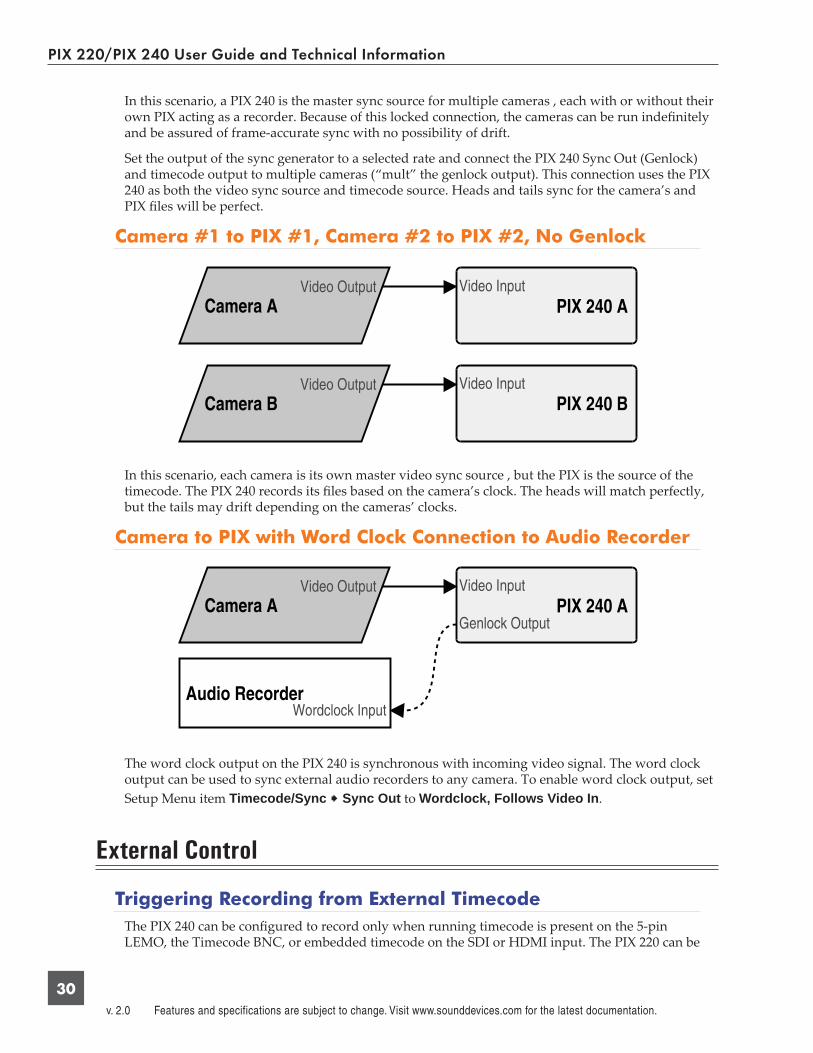
In this scenario, a PIX 240 is the master sync source for multiple cameras , each with or without their own PIX acting as a recorder. Because of this locked connection, the cameras can be run indefi nitely and be assured of frame-accurate sync with no possibility of drift.
Set the output of the sync generator to a selected rate and connect the PIX 240 Sync Out (Genlock) and timecode output to multiple cameras (“mult” the genlock output). This connection uses the PIX 240 as both the video sync source and timecode source. Heads and tails sync for the camera’s and PIX fi les will be perfect.
Camera #1 to PIX #1, Camera #2 to PIX #2, No Genlock
In this scenario, each camera is its own master video sync source , but the PIX is the source of the timecode. The PIX 240 records its fi les based on the camera’s clock. The heads will match perfectly, but the tails may drift depending on the cameras’ clocks.
Camera to PIX with Word Clock Connection to Audio Recorder
The word clock output on the PIX 240 is synchronous with incoming video signal. The word clock output can be used to sync external audio recorders to any camera. To enable word clock output, set Setup Menu item Timecode/Sync Sync Out to Wordclock, Follows Video In.
External Control
Triggering Recording from External TimecodeThe PIX 240 can be confi gured to record only when running timecode is present on the 5-pin LEMO, the Timecode BNC, or embedded timecode on the SDI or HDMI input. The PIX 220 can be
PIX 220/PIX 240 User Guide and Technical Information
31
confi gured to record only when running timecode is present on HDMI input. The device that is sending timecode to the PIX recorder must be confi gured to send running timecode when recording and stopped timecode when not recording (often referred to as “Rec Run”). To make the PIX record-er record automatically when running timecode is sensed on the timecode input:
1. Set Setup Menu option System Rec Start/Stop to Timecode
2. Make sure that the device that is sending timecode is confi gured to send stopped timecode while stopped and running timecode while recording.
Triggering from external timecode will not cause the PIX 240 to automatically stamp external timecode to recorded fi les. The timecode stamped to fi les is determined by the sett ing Timecode/Sync Time-code Mode
Triggering Recording from SDI Flag BitsStart and stop fl ags embedded in the SDI signal from some cameras can be used to start and stop recording of the PIX 240. To enable this feature, set Setup Menu option System Rec Start/Stop to the SDI Flag option that refers to the manufacturer of the connected camera.
LANCThe LANC protocol can be used to start and stop recording of the PIX. A standard LANC controller can be plugged into the 2.5 mm LANC connector on the right panel of the PIX recorder. When Setup Menu option System Rec Start/Stop is to LANC In, the PIX recorder will follow commands from the LANC controller. LANC commands recognized by the PIX recorder are Start and Stop recording.
To send LANC commands from a controller to both a camera and a PIX recorder (or to use more than one PIX recorder), parallel the LANC signal with a Y-cable running to both the camera and the PIX. Set the Setup Menu option System Rec Start/Stop to LANC (parallel) for any paralleled PIX units.
Switch Contact ClosureThe 2.5 mm LANC connector can alternatively be confi gured to function as a standard GPIO logic connection by sett ing the Setup Menu option System Rec Start/Stop to Switch Closure or Switch Momentary. When in either of these modes, the 2.5 mm TRS “LANC” connection is no longer used as a LANC input and the recorder will no longer function with a LANC controller. The wiring of the TRS connector is:
• Tip: Switch Input• Ring: +5V LED voltage output (for illuminating an LED light for record tally)• Sleeve: Ground
When the Setup Menu option System Rec Start/Stop to Switch Closure, recording will begin when the Switch Input (tip) is connected to ground (sleeve) and recording will stop when the Switch Input (tip) is disconnected from ground (sleeve). When the Setup Menu option System Rec Start/Stop to Switch Momentary, recording will begin when the Switch Input (tip) is connected to ground (sleeve) and recording will stop when the Switch Input (tip) is connected to ground (sleeve) a subsequent time.
To use the LED output, connect an LED between the 2.5mm ring and sleeve with a series resistor. The anode (+) of the LED should connect to the ring and the cathode (-) to the sleeve. A good starting point for the resistor value is 220 ohms, but the value depends on the particular LED used. The ring is internally connected to 5V when recording (and to 0V otherwise) with a series 100 ohm resistor.
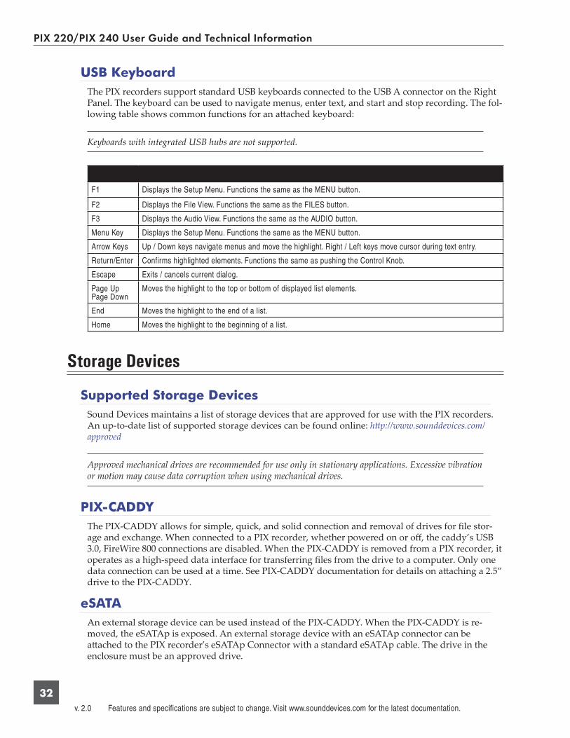
PIX 220/PIX 240 User Guide and Technical Information
v. 2.0 Features and specifications are subject to change. Visit www.sounddevices.com for the latest documentation.
32
USB KeyboardThe PIX recorders support standard USB keyboards connected to the USB A connector on the Right Panel. The keyboard can be used to navigate menus, enter text, and start and stop recording. The fol-lowing table shows common functions for an att ached keyboard:
Keyboards with integrated USB hubs are not supported.
F1 Displays the Setup Menu. Functions the same as the MENU button.
F2 Displays the File View. Functions the same as the FILES button.
F3 Displays the Audio View. Functions the same as the AUDIO button.
Menu Key Displays the Setup Menu. Functions the same as the MENU button.
Arrow Keys Up / Down keys navigate menus and move the highlight. Right / Left keys move cursor during text entry.
Return/Enter Confirms highlighted elements. Functions the same as pushing the Control Knob.
Escape Exits / cancels current dialog.
Page UpPage Down
Moves the highlight to the top or bottom of displayed list elements.
End Moves the highlight to the end of a list.
Home Moves the highlight to the beginning of a list.
Storage Devices
Supported Storage DevicesSound Devices maintains a list of storage devices that are approved for use with the PIX recorders. An up-to-date list of supported storage devices can be found online: htt p://www.sounddevices.com/approved
Approved mechanical drives are recommended for use only in stationary applications. Excessive vibration or motion may cause data corruption when using mechanical drives.
PIX-CADDYThe PIX-CADDY allows for simple, quick, and solid connection and removal of drives for fi le stor-age and exchange. When connected to a PIX recorder, whether powered on or off , the caddy’s USB 3.0, FireWire 800 connections are disabled. When the PIX-CADDY is removed from a PIX recorder, it operates as a high-speed data interface for transferring fi les from the drive to a computer. Only one data connection can be used at a time. See PIX-CADDY documentation for details on att aching a 2.5” drive to the PIX-CADDY.
eSATAAn external storage device can be used instead of the PIX-CADDY. When the PIX-CADDY is re-moved, the eSATAp is exposed. An external storage device with an eSATAp connector can be att ached to the PIX recorder’s eSATAp Connector with a standard eSATAp cable. The drive in the enclosure must be an approved drive.

PIX 220/PIX 240 User Guide and Technical Information
33
This port can be used to power an external drive via 5V eSATAp, or it can be used with powered external enclosures using an eSATA (non-powered) cable.
File Storage
PIX recorders format and write to a UDF (v2.50) fi lesystem. The UDF fi lesystem is readable and writ-able by Mac OS X, Windows 7, and Windows Vista. Files stored in a UDF fi lesystem are not restrict-ed to 4GB, unlike FAT32 (a commonly utilized fi lesystem in other digital recorders). 2.5” drive and CF storage devices to be used with the PIX recorder must be formatt ed from the PIX recorder.
Mounting PIX formatt ed UDF volumes to virtual machines is not supported.
UDF volumes are not readable by Windows XP. A third-party UDF driver that enables writing to UDF volumes is available for Windows XP, however it is not offi cially supported for use with PIX for-matt ed volumes: htt p://www.softarch.com/EN/Product/WriteUDFWin.html
FormattingTo format a drive:
1. Make sure the CF or 2.5” drive to be formatt ed is connected to the recorder.
2. Open Setup Menu option File Storage Erase/Re-format.
3. Choose the appropriate Erase/Re-format sub-option for the drive to be formatt ed (SSD or CF).
4. A confi rmation dialog will appear: “All data will be erased. Continue?”. Turn the control knob to select OK.
5. Use the displayed on-screen keyboard (or an external USB keyboard, if att ached) to enter a volume label for the drive, and then use the Control Knob to select OK to initiate the format.
Target Storage Device for RecordingThe PIX recorder can record directly to approved CF or 2.5” drives. The Setup Menu option File Storage Primary Drive controls which drive will be writt en to depending on which drives are att ached. When the primary drive is full, the PIX recorder can be confi gured to automatically begin recording to the other drive or stop recording, with the Setup Menu option File Storage When Drive is Full.
Notes on automatic drive switching:• If the drive that is set as the primary drive is not att ached when the Record butt on is pressed,
the PIX will record to the alternate drive (if present).

PIX 220/PIX 240 User Guide and Technical Information
v. 2.0 Features and specifications are subject to change. Visit www.sounddevices.com for the latest documentation.
34
• In order for automatic switching to occur, the drive to be switched to must be att ached and mounted prior to hitt ing Record. Drives that are not mounted prior to hitt ing record will not be available for automatic switching until recording is Stopped.
File Management and Metadata
File ViewFiles recorded on the PIX recorder are compiled in the File View as a list of clips. Push the Files butt on to access the File View. Clips are arranged chronologically and grouped by Reel. Turn the Control Knob to highlight individual rows in File View.
When the reel number is changed (File Storage Reel) and a new clip is recorded, a new group will be created in the fi le list. Rows with a grey background indicate a group of clips by Reel num-ber. The number of clips in the reel is indicated, and the total size (in GB) of the clips within the reel is also indicated. To browse the clips within a group, highlight the group and push the Control Knob.
Clips that exceed the time set in Setup Menu option File Storage File Split every will consist of more than one fi le and be grouped into one row in the File View. Clips grouped in this way will be indicated with a number following the clip name. This number represents the amount of fi les in the clip. Pushing the Control Knob when a multi-fi le clip is highlighted will open a sub-list of the fi les that make up the clip.
Reel groupNumber of clips in the reel indicated in brackets. Press Control Knob to expand or collapse.
ClipMulti-file clip. Number of files in the clip indicated in brackets. Press Control Knob to expand or collapse. Press Play to play first file.
FileFile of a multi-file clip. Only shown when clip is expanded. Press Control Knob to view details. Press Play to play.
ClipSingle file clip. Press Control Knob to view details. Press Play to play.
File Details
Highlight a fi le and push the Control Knob to view the File Details of that fi le. File detail includes:• Start time code• Timecode frames-per-second• Timecode user bits• Video resolution• Video frame rate• Video codec
• Media• File size• Duration• Audio Format

PIX 220/PIX 240 User Guide and Technical Information
35
Deleting a File
To delete a fi le:
1. Push the fi les butt on to enter the File View.
2. Scroll with the Control Knob to highlight and select the fi le to be deleted.
3. Highlight and select the Delete option. A dialog will appear to confi rm the deletion. Turn the Control Knob to highlight and select “OK”.
File Size LimitTo aid in maintaining manageable fi le sizes, the PIX recorder will automatically begin writing a new fi le after a set amount of minutes has elapsed in a recording. The beginning of this new fi le will be seamless to the ending of the previous fi le. The default time before splitt ing the fi le is 60 minutes. The Setup Menu option File Storage File Split every adjusts the amount of time before a fi le split occurs.
File Naming
Files are named according to the fi le name format as set with Setup Menu option File Storage File Name Format. The options for fi le name format include various combinations of CamID, Reel, Clip, Scene/Shot, and Take metadata fi elds.
RED File Format
When the Setup Menu option File Storage File Name Format is set to RED File Format, the PIX 240 will:
• Generate fi les that follow the same naming convention used by RED cameras.• Extract the CamID, Reel number, and Clip number from the SDI input signal from a RED One
or RED Epic camera and apply it to the fi le name and appropriate metadata fi elds of each recorded fi le. See Metadata

PIX 220/PIX 240 User Guide and Technical Information
v. 2.0 Features and specifications are subject to change. Visit www.sounddevices.com for the latest documentation.
36
MetadataSeveral parameters can be set within the Setup Menu File Storage to aid in the organization of fi les. This metadata can be used in naming the fi le which is to be recorded. Folders are created on the 2.5” drive or CF card based on the Reel number. The Reel number and start timecode value are recorded within the Quicktime’s metadata fi elds.
CamID
The CamID fi eld consists of a single alpha character. It is intended to indicate which physical camera shot the content for the take.
Reel
The reel can be considered a container for all assets generat-ed during a recording session or day’s work. This fi eld con-sists of a numeric value between 1 and 999. It is intended to indicate what reel the recording is part of. The PIX recorder will create a folder at the root level for each Reel. Recorded fi les are placed inside the current Reel folder.
Clip
The Clip fi eld consists of a numeric value between 1 and 999. It is intended to indicate what clip number the recording is. This fi eld can be set manually and will increment each time a new fi le is recorded. The Clip number will reset to 1 when the Reel number is changed.
Scene/Shot
The Scene/Shot fi eld consists of a alpha-numeric value. Use this fi eld to indicate a descriptive name for the current scene or shot.
Take
The Take fi eld consists of a numeric value between 1 and 999. It is intended to indicate what take number the clip is, relative to the scene. This fi eld can be set manually and will increment each time a new fi le is recorded. The Take number will reset to 1 when the Scene name is changed.
Transfering Files to a ComputerQuicktime fi les on PIX formatt ed storage volumes (2.5” drive, CF card, or any external storage device) can be copied to a computer by removing the storage device from the PIX recorder and con-necting it to a computer. Storage devices formatt ed with the PIX recorder use the UDF fi lesystem. See File Storage
The Firewire 800 and USB 3.0 connectors on the PIX-CADDY are disabled when the PIX-CADDY is att ached to the PIX recorder. When att aching the PIX-CADDY to a computer, either the Firewire 800 or the USB 3.0 connection must be used; Not both.
Sound Devices recommends fi rst copying fi les from the 2.5” drive or CF card to the computer fi rst and then editing the fi les. It is not recommended to edit fi les directly off of the 2.5” drive or CF card.
Do not copy fi les from a computer (or any other host device) to a drive that is intended to be used by the PIX recorder. If this occurs, it is advisable to format the drive with the PIX recorder before making new recordings.

PIX 220/PIX 240 User Guide and Technical Information
37
Firmware Upgrades
At times, Sound Devices makes updates available for PIX recorders. These updates are easy to apply:
1. Download the new .prg fi le from the Sound Devices website.
2. Copy this fi le to the CF card or 2.5” drive, and insert into the PIX recorder.
3. Ensure that the power source for the PIX recorder is reliable. Power loss during a fi rmware upgrade process can produce unexpected results.
4. From the System menu in the Setup Menu, select Firmware Update. The PIX recorder will search for the .prg fi le and give the option to install the fi rst fi le that it fi nds (cancelling this dialog will cause the PIX to search for another .prg on any att ached storage devices). When the correct .prg fi le has been located, highlight the OK butt on and push the Control Knob to begin the fi rmware update.
5. The PIX will verify that the fi le is not corrupted, then it will update the fi rmware. When done the unit will need to be powered down and then back up.
Setup Management
Saving and Loading Setup Files
To save all of the sett ings to a setup fi le, select the Setup Menu option Quick Setup Save Settings to SSD or Save Settings to CF. Use the on-screen keyboard (or att ached USB keyboard) to enter a name for the setup fi le. This will save all of the current sett ings to an XML fi le on the root of the selected storage device. To load a previously saved setup fi le, select the Setup Menu option Quick Setup Load Settings from SSD or Load Settings from CF.
For a complete list of available Setup Menu options, see Setup Menu Options.
Formatt ing a storage device will also remove any setup fi les that are on the drive. Setup fi les can be stored on a computer and copied back to a CF or 2.5” drive to be loaded on the PIX recorder.
Custom Default Settings and Setup Menu Option Visibility
The Setup Menu option Quick Setup Load Factory Settings loads a setup that is saved inter-nally to the PIX when it leaves the factory. It is possible to alter this “factory” setup, so that the Setup Menu option Quick Setup Load Factory Settings will load a custom default.
It is also possible to hide specifi c Setup Menu parameters and options. This is useful for Setup Menu options that are not commonly used in a particular workfl ow, or to simplify use when lending the unit to another user.
To customize defaults and Setup Menu option visibility:
1. Att ach a USB keyboard to the PIX recorder’s USB keyboard jack.
2. Press the MENU butt on to enter the Setup Menu.
3. Press Ctrl + Alt + F10 on the keyboard. If this is the fi rst time this action has been performed since powering the PIX recorder up, a password dialog will appear. Enter the password (the default password is “default”).

PIX 220/PIX 240 User Guide and Technical Information
v. 2.0 Features and specifications are subject to change. Visit www.sounddevices.com for the latest documentation.
38
4. After the correct password has been entered, the Sett ings Customization Menu will appear. Select Edit Menu & Default Values.
5. The Setup Menu will be shown with a colored background. There will be check boxes next to each menu item. Navigate the menu with the Control Knob, as usual.
6. To to change the visibility of an item in the Setup Menu, push the spacebar on the keyboard while the item is highlighted. Checked items will be displayed in the Setup Menu and un-checked items will not be displayed.

PIX 220/PIX 240 User Guide and Technical Information
39
Crossed out items will be hidden
7. Sett ings changed at this point will become the default sett ings.
8. When fi nished, press Esc or F1 on the keyboard. This will show the Sett ings Customization Menu again. Select any of the save options.
Keep a record of the password, if it is changed. A lost password could result in undesirable limitations.
The Sett ings Customization Menu option Reset to Factory Settings will make all Setup Menu items visible and revert default sett ings to factory defaults.

PIX 220/PIX 240 User Guide and Technical Information
v. 2.0 Features and specifications are subject to change. Visit www.sounddevices.com for the latest documentation.
40
Setup Menu Options
The Setup Menu controls a wide range of parameters for the PIX. The parameters are organized into categories, making the setup Menu easy to navigate. The following tables show the parameter name, a description, options available, and the factory default sett ing where applicable.
Default sett ings can be altered. See Setup Management
File Storage
# Parameter Name Description Options1 Primary Drive Selects which storage device to record to. » SSD
• CF
2 When Drive is Full Whether or not to automatically switch to the other storage device if the primary drive becomes full while recording.
» Stop recording• Switch to other drive
3 File Split Every Choose the recording time that will elapse before a new file is created automatically. Since ProRes and DNxHD codecs are variable bit rate, the size of each file will vary, even though the running time will be the same.
• 1 min• 5 min• 10 min• 15 min• 30 min
» 60 min
4 File Name Format The format for file names as they are written to the drive.
» Drive_Reel_Clip.mov• Reel_Clip.mov• CamID_Reel_Clip.mov• Reel_Scene_Take.mov• Scene_Take.mov• RED File Format
5 CamID » A(single alpha to “Z”).
6 Reel • 1(numeric)
7 Clip » 1(numeric)
8 Scene/Shot » “Scene 1”(multi alphanumeric)
9 Take » 1(numeric)
10 Erase/Reformat • Erase/Re-format: SSD• Erase/Re-format: CF

PIX 220/PIX 240 User Guide and Technical Information
41
Video
# Parameter Name Description Options1 Video Input Physical source to derive recorded video from. • HDMI
» SDI
12
File Resolution/Rate The resolution and frame to convert input video to. This will affect files recorded and all video outputs.
» Same as Video Input• 1080p30/29.97• 1080p25• 1080p24/23.976• 1080i60/59.94• 1080i50• 1080PsF30/29.97• 1080PsF25• 1080PsF24/23.976• 720p60/59.94• 720p50• 720p30/29.97• 720p25• 720p24/23.976• 576i59 (PAL)• 480i59.94 (NTSC)
23
Codec The video codec to use for encoding. Note for DNxHD that the rates listed are assuming 1080p30. If a dif-ferent resolution and frame rate is selected, the PIX recorder will use the corresponding DNxHD data rate.
• DNxHD 220x 220Mb/s, 10bit• DNxHD 220 220Mb/s, 8bit• DNxHD 145 145Mb/s, 8bit• DNxHD 36 36Mb/s, 8bit• ProRes 422HQ 220Mb/s, 10bit
» ProRes 422 145Mb/s, 10bit• ProRes 422LT 100Mb/s, 8bit• ProRes 422Proxy 36Mb/s, 8bit
34
Input PsF Detect When set to “Auto”, the PIX will sense PsF signal based on a flag within the signal stream. Most devices with SDI output will provide this flag, however some SDI outputs and all HDMI outputs will not provide this flag. When sending PsF signal from these devices, choose “Interpret 1080i as PsF”
» Auto• Interpret 1080i as PsF
Audio
# Parameter Name Description Options1 Audio Input Physical source to derive recorded audio from. » Analog XLR
• AES (Digital) XLR 1-2ch• AES (Digital) XLR 1-4ch• SDI/HDMI 2ch• SDI 4ch• SDI 6ch• SDI 8ch• Analog 2ch + SDI/HDMI 2ch• Analog 2ch + SDI 4ch• Analog 2ch + SDI 6ch• OFF
2 Analog 1 Source Selects the input level and whether or not phantom power should be applied to analog input 1.
» Mic• Mic 48V• Line• Line 48V
3 Analog 2 Source Selects the input level and whether or not phantom power should be applied to analog input 2.
» Mic• Mic 48V• Line• Line 48V

PIX 220/PIX 240 User Guide and Technical Information
v. 2.0 Features and specifications are subject to change. Visit www.sounddevices.com for the latest documentation.
42
# Parameter Name Description Options4 Analog 1 Low cut Engages low-cut filter on analog Input 1 at the speci-
fied frequency. » OFF
• 40Hz• 80Hz• 120Hz• 160Hz• 200Hz• 240Hz
5 Analog 2 Low cut Engages low-cut filter on analog Input 2 at the speci-fied frequency.
» OFF• 40Hz• 80Hz• 120Hz• 160Hz• 200Hz• 240Hz
6 Low cut Slope Selects the curve of the analog low-cut filters. • 6dB/oct » 12dB/oct
7 input Limiter (1,2) Toggles input limiters on analog inputs. » On• Off
8 Analog 1 Polarity Selects normal or inverse polarity for analog Input 1. » Normal• Reverse
9 Analog 2 Polarity Selects normal or inverse polarity for analog Input 2. » Normal• Reverse
10 Input 1 Delay Applies the specified amount (in milliseconds) of digital delay to Input 1.
» 0ms(numeric 0-200)
11 Input 2 Delay Applies the specified amount (in milliseconds) of digital delay to Input 2.
» 0ms(numeric 0-200)
12 Input 3 Delay Applies the specified amount (in milliseconds) of digital delay to Input 3.
» 0ms(numeric 0-200)
13 Input 4 Delay Applies the specified amount (in milliseconds) of digital delay to Input 4.
» 0ms(numeric 0-200)
1214
Input Linking Selects whether Input 1 and Input 2 gains are con-trolled independantly (Unlinked), together (1-2), or together with MS decoding (1-2MS).
» Unlinked• 1-2• 1-2MS
1315
Output Source - XLR The audio channels sent to the analog XLR outputs. Left of the comma represents left output and right of the comma represents right output.
» 1,2• 3,4• 5,6• 7,8• 1357,2468• 12345678
1416
Output XLR 1 Attenuation Attenuate analog output 1 by 1 dB increments. » 0 dB(numeric 0-20)
1517
Output XLR 2 Attenuation Attenuate analog output 2 by 1 dB increments » 0 dB(numeric 0-20)
1618
Headphone Source The audio channels sent to the headphone output. Left of the comma represents left headphone channel and right of the comma represents right headphone channel.
» 1,2• 3,4• 5,6• 7,8• 1357,2468• 12345678
1719
Headphone: LCD A/V Align Delays audio to Headphone output to align with video on LCD.
» Off• On
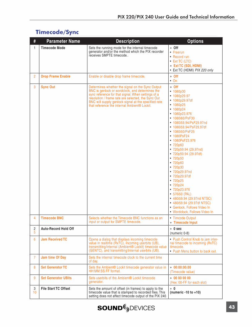
PIX 220/PIX 240 User Guide and Technical Information
43
Timecode/Sync
# Parameter Name Description Options1 Timecode Mode Sets the running mode for the internal timecode
generator and/or the method which the PIX recorder receives SMPTE timecode..
» Off• Freerun• Record run• Ext TC (LTC)
» Ext TC (SDI, HDMI)• Ext TC (HDMI) PIX 220 only
2 Drop Frame Enable Enable or disable drop frame timecode. » Off• On
3 Sync Out Determines whether the signal on the Sync Output BNC is genlock or wordclock, and determines the sync reference for that signal. When settings of a resolution / frame rate are selected, the Sync Out BNC will supply genlock signal at the specified rate that reference the internal Ambient® Lockit.
» Off• 1080p30• 1080p29.97• 1080p29.97df• 1080p25• 1080p24• 1080p23.976• 1080i60/PsF30• 1080i59.94/PsF29.97nd• 1080i59.94/PsF29.97df• 1080i50/PsF25• 1080PsF24• 1080PsF23.976• 720p60• 720p59.94 (29.97nd)• 720p59.94 (29.97df)• 720p50• 720p60• 720p30• 720p29.97nd• 720p29.97df• 720p25• 720p24• 720p23.976• 576i50 (PAL)• 480i59.94 (29.97nd NTSC)• 480i59.94 (29.97df NTSC)• Genlock, Follows Video In• Wordclock, Follows Video In
4 Timecode BNC Selects whether the Timecode BNC functions as an input or output for SMPTE timecode.
• Timcode Output » Timecode Input
25
Auto-Record Hold Off » 0 sec(numeric 0-8)
6 Jam Received TC Opens a dialog that displays incoming timecode value in realtime (RxTC), incoming userbits (UB), transmitting/internal (Ambient® Lockit) timecode value (GENTC), and transmitting/internal userbits (UB).
• Push Control Knob to jam inter-nal timecode to incoming (RxTC) timecode.• Push Menu button to back out.
7 Jam time Of Day Sets the internal timecode clock to the current time of day.
8 Set Generator TC Sets the Ambient® Lockit timecode generator value in HH:MM:SS.FF format.
» 00:00:00.00(Timecode value)
9 Set Generator UBits Sets userbits of the Ambient® Lockit timecode generator.
» 00 00 00 00(Hex: 00-FF for each slot)
310
File Start TC Offset Sets the amount of offset (in frames) to apply to the timecode value that is stamped to recorded files. This setting does not affect timecode output of the PIX 240.
» 0(numeric -10 to +10)
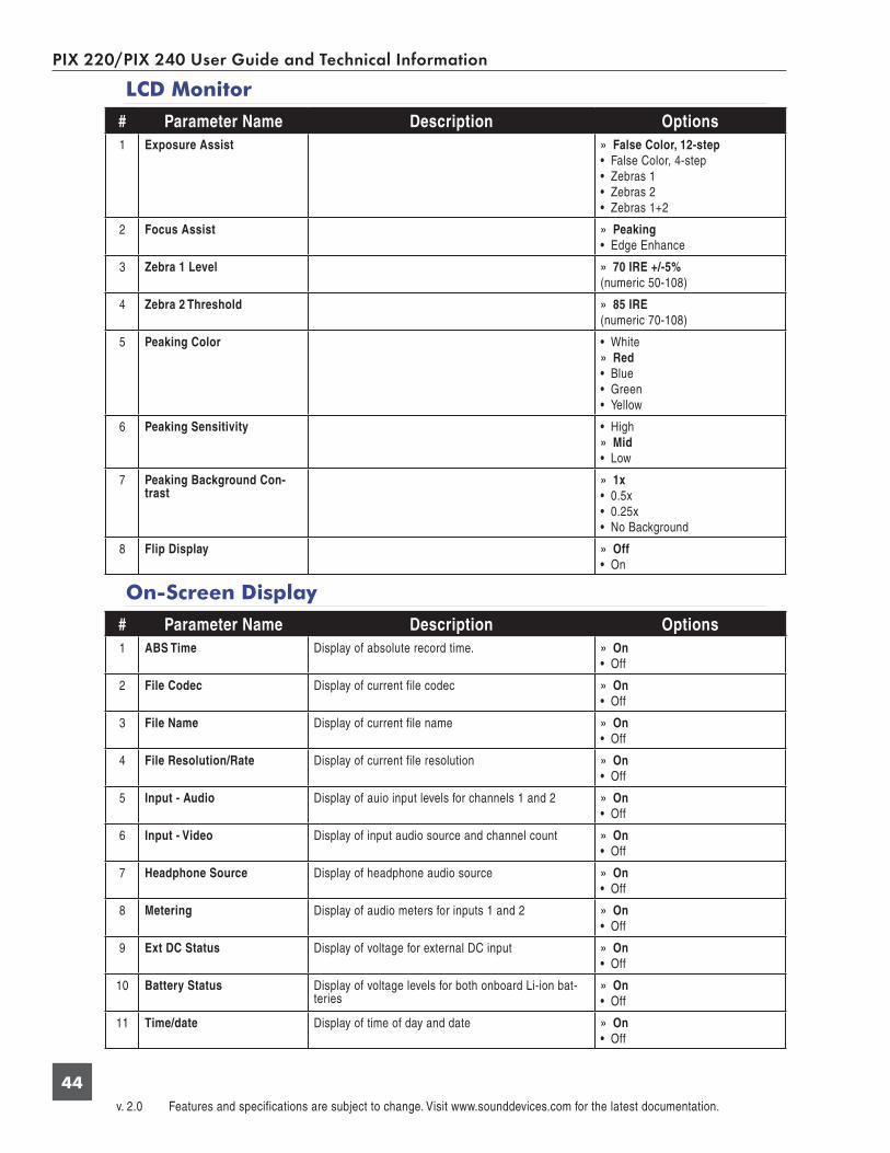
PIX 220/PIX 240 User Guide and Technical Information
v. 2.0 Features and specifications are subject to change. Visit www.sounddevices.com for the latest documentation.
44
LCD Monitor
# Parameter Name Description Options1 Exposure Assist » False Color, 12-step
• False Color, 4-step• Zebras 1• Zebras 2• Zebras 1+2
2 Focus Assist » Peaking• Edge Enhance
3 Zebra 1 Level » 70 IRE +/-5%(numeric 50-108)
4 Zebra 2 Threshold » 85 IRE(numeric 70-108)
5 Peaking Color • White » Red
• Blue• Green• Yellow
6 Peaking Sensitivity • High » Mid
• Low
7 Peaking Background Con-trast
» 1x• 0.5x• 0.25x• No Background
8 Flip Display » Off• On
On-Screen Display
# Parameter Name Description Options1 ABS Time Display of absolute record time. » On
• Off
2 File Codec Display of current file codec » On• Off
3 File Name Display of current file name » On• Off
4 File Resolution/Rate Display of current file resolution » On• Off
5 Input - Audio Display of auio input levels for channels 1 and 2 » On• Off
6 Input - Video Display of input audio source and channel count » On• Off
7 Headphone Source Display of headphone audio source » On• Off
8 Metering Display of audio meters for inputs 1 and 2 » On• Off
9 Ext DC Status Display of voltage for external DC input » On• Off
10 Battery Status Display of voltage levels for both onboard Li-ion bat-teries
» On• Off
11 Time/date Display of time of day and date » On • Off

PIX 220/PIX 240 User Guide and Technical Information
45
# Parameter Name Description Options12 Timecode Display of current timecode value » On
• Off
12 SSD Status Display of time remaining (or offline) status of the SSD
» On • Off
13 CF Status Display of time remaining (or offline) status of the CF card
» On • Off
14 Cue Marker Display of cue information during playback » On • Off
System
# Parameter Name Description Options1 Test Signal Generator » Off
• On
2 Audio Tone Level The level (in dBFS) of generated audio tone. » -20dBFS(numeric -40 - 0)
3 HP Warning Bell Level Adjusts the level of the heaphone warning bell sound » -20dBFS(Off to -12dBFS)
4 Time Zone Selects the international timezone » (GMT-06:00) Central Time (US)(All GMT zones)
5 Daylight Saving Toggles daylight saving on or off for the time-of-day clock
» Off• On
6 Time Format Selects between 12 or 24 hour format for the time-of-day clock
» 12h• 24h
7 Date Format Selects between MM/DD/YY and DD/MM/YY date format
» MM/DD/YY• DD/MM/YY
8 Set Date/Time Set the time and date
9 Rec Start/Stop Determines what method the PIX recorder uses to automatically start and stop recording.
» Switch Closure• Switch Momentary• LANC In• LANC Through• SDI Flag - RED• SDI Flag - Panasonic• SDI Flag - Panasonic (Varicam)• SDI Flag - Canon• SDI Flag - Sony• SDI Flag - Arri• SDI Flag - PIX• Timecode
10 Rec button File Split Whether or not a new file will be created when the REC button is pushed during recording.
• On » Off
11 Playback Mode Upon reaching the end of a file during playback, the PIX recorder will return to the Main View (Play Once) or pause on the last frame (Play Once - Pause)
» Play Once• Play Once - Pause
12 Shortcuts Displays a dialog that shows all shortcut button combi-nations. This is not a setting, but a helpful reference.
13 Info Displays a dialog indicating firmware version and serial number. This is not a setting, but a helpful refer-ence.
14 Update Software Searches attached drives for a .prg firmware file and begins the firmware update process.

PIX 220/PIX 240 User Guide and Technical Information
v. 2.0 Features and specifications are subject to change. Visit www.sounddevices.com for the latest documentation.
46
Quick Setup
# Parameter Name Description Options1 Load Factory Settings Loads default setup
2 Load Settings From SSD Loads selected setup from setups saved on the SSD • All settings files located on SSD
3 Load Settings From CF Loads selected setup from setups saved on the CF • All settings files located on CF
4 Save Settings to SSD Opens dialog to name and save current setup to SSD
5 Save Settings to CF Opens dialog to name and save current setup to CF
Button Shortcuts
Button Combination EffectAUDIO + Control Knob push Select headphone audio source.
AUDIO + Control Knob rotate Adjust headphone gain.
LCD + Control Knob push Adjust LCD and button brightness.
Hold LCD Turns off LCD display.
MENU + FILES Button lock options: Unlock Buttons, Lock Non-Transport Buttons, or Lock All Buttons.
STOP + REW False take.
LCD + AUDIO Toggle Zoom on LCD display
LCD + MENU Toggle Focus Assist on LCD display
LCD + FILES Toggle Exposure Assist on LCD display
PLAY + FF Begin looping between cue points when in loop playback mode
PLAY + REW Begin looping of clip when in loop playback mode
FILES When in playback mode: Set a cue point
Hold FILES When in playback mode: Delete last cue point
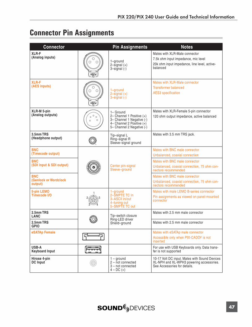
PIX 220/PIX 240 User Guide and Technical Information
47
Connector Pin Assignments
Connector Pin Assignments NotesXLR-F(Analog inputs)
1–ground2–signal (+)3–signal (-)
Mates with XLR-Male connector7.5k ohm input impedance, mic level20k ohm input impedance, line level, active-balanced
XLR-F(AES inputs)
1–ground2–signal (+)3–signal (-)
Mates with XLR-Male connectorTransformer balancedAES3 specification
XLR-M 5-pin(Analog outputs)
1– Ground2– Channel 1 Positive (+)3– Channel 1 Negative (-)4– Channel 2 Positive (+)5– Channel 2 Negative (-)
Mates with XLR-Female 5-pin connector120 ohm output impedance, active balanced
3.5mm TRS(Headphone output)
Tip–signal L Ring–signal R Sleeve–signal ground
Mates with 3.5 mm TRS jack.
BNC(Timecode output)
Center pin–signalSleeve–ground
Mates with BNC male connectorUnbalanced, coaxial connection
BNC(SDI input & SDI output)
Mates with BNC male connectorUnbalanced, coaxial connection, 75 ohm con-nectors recommended
BNC(Genlock or Wordclock output)
Mates with BNC male connectorUnbalanced, coaxial connection, 75 ohm con-nectors recommended
5-pin LEMOTimecode I/O
1–ground 2–SMPTE TC In 3–ASCII in/out 4–tuning out 5–SMPTE TC out
Mates with male LEMO B-series connectorPin assignments as viewed on panel-mounted connector
2.5mm TRSLANC Tip–switch closure
Ring-LED driverShield–ground
Mates with 2.5 mm male connector
2.5mm TRSGPIO
Mates with 2.5 mm male connector
eSATAp Female Mates with eSATAp male connectorAccessible only when PIX-CADDY is not inserted
USB-AKeyboard Input
For use with USB Keyboards only. Data trans-fer is not supported
Hirose 4-pin DC Input
1 – ground 2 – not connected3 – not connected 4 – DC (+)
10-17 Volt DC input. Mates with Sound Devices XL-NPH and XL-WPH3 powering accessories. See Accessories for details.
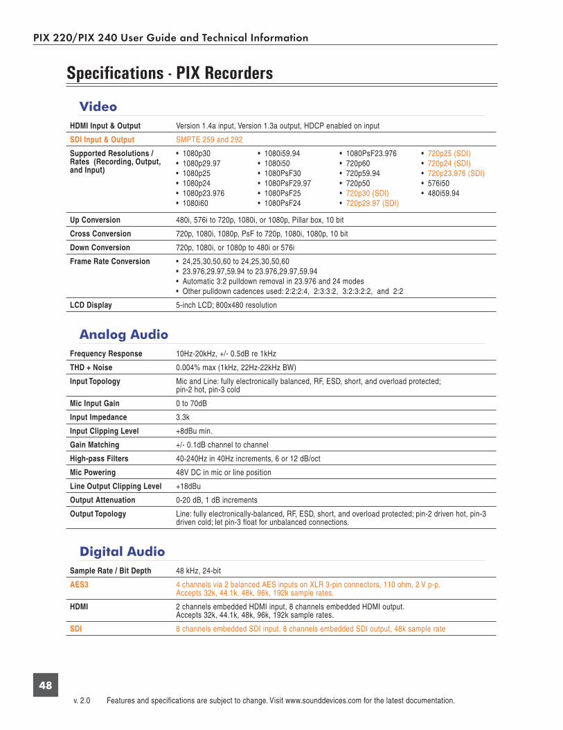
PIX 220/PIX 240 User Guide and Technical Information
v. 2.0 Features and specifications are subject to change. Visit www.sounddevices.com for the latest documentation.
48
Specifi cations - PIX Recorders
VideoHDMI Input & Output Version 1.4a input, Version 1.3a output, HDCP enabled on input
SDI Input & Output SMPTE 259 and 292
Supported Resolutions / Rates (Recording, Output, and Input)
• 1080p30• 1080p29.97• 1080p25• 1080p24• 1080p23.976• 1080i60
• 1080i59.94• 1080i50• 1080PsF30• 1080PsF29.97• 1080PsF25• 1080PsF24
• 1080PsF23.976• 720p60• 720p59.94• 720p50• 720p30 (SDI)• 720p29.97 (SDI)
• 720p25 (SDI)• 720p24 (SDI)• 720p23.976 (SDI)• 576i50• 480i59.94
Up Conversion 480i, 576i to 720p, 1080i, or 1080p, Pillar box, 10 bit
Cross Conversion 720p, 1080i, 1080p, PsF to 720p, 1080i, 1080p, 10 bit
Down Conversion 720p, 1080i, or 1080p to 480i or 576i
Frame Rate Conversion • 24,25,30,50,60 to 24,25,30,50,60• 23.976,29.97,59.94 to 23.976,29.97,59.94• Automatic 3:2 pulldown removal in 23.976 and 24 modes• Other pulldown cadences used: 2:2:2:4, 2:3:3:2, 3:2:3:2:2, and 2:2
LCD Display 5-inch LCD; 800x480 resolution
Analog AudioFrequency Response 10Hz-20kHz, +/- 0.5dB re 1kHz
THD + Noise 0.004% max (1kHz, 22Hz-22kHz BW)
Input Topology Mic and Line: fully electronically balanced, RF, ESD, short, and overload protected; pin-2 hot, pin-3 cold
Mic Input Gain 0 to 70dB
Input Impedance 3.3k
Input Clipping Level +8dBu min.
Gain Matching +/- 0.1dB channel to channel
High-pass Filters 40-240Hz in 40Hz increments, 6 or 12 dB/oct
Mic Powering 48V DC in mic or line position
Line Output Clipping Level +18dBu
Output Attenuation 0-20 dB, 1 dB increments
Output Topology Line: fully electronically-balanced, RF, ESD, short, and overload protected; pin-2 driven hot, pin-3 driven cold; let pin-3 float for unbalanced connections.
Digital AudioSample Rate / Bit Depth 48 kHz, 24-bit
AES3 4 channels via 2 balanced AES inputs on XLR 3-pin connectors, 110 ohm, 2 V p-p.Accepts 32k, 44.1k, 48k, 96k, 192k sample rates.
HDMI 2 channels embedded HDMI input, 8 channels embedded HDMI output.Accepts 32k, 44.1k, 48k, 96k, 192k sample rates.
SDI 8 channels embedded SDI input, 8 channels embedded SDI output, 48k sample rate
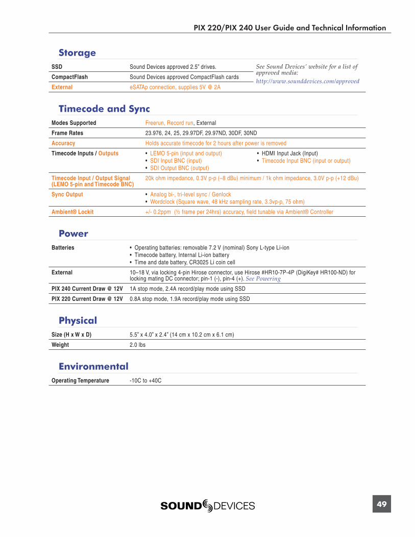
PIX 220/PIX 240 User Guide and Technical Information
49
StorageSSD Sound Devices approved 2.5” drives. See Sound Devices’ website for a list of
approved media:http://www.sounddevices.com/approved
CompactFlash Sound Devices approved CompactFlash cards
External eSATAp connection, supplies 5V @ 2A
Timecode and SyncModes Supported Freerun, Record run, External
Frame Rates 23.976, 24, 25, 29.97DF, 29.97ND, 30DF, 30ND
Accuracy Holds accurate timecode for 2 hours after power is removed
Timecode Inputs / Outputs • LEMO 5-pin (input and output)• SDI Input BNC (input)• SDI Output BNC (output)
• HDMI Input Jack (Input)• Timecode Input BNC (input or output)
Timecode Input / Output Signal(LEMO 5-pin and Timecode BNC)
20k ohm impedance, 0.3V p-p (–8 dBu) minimum / 1k ohm impedance, 3.0V p-p (+12 dBu)
Sync Output • Analog bi-, tri-level sync / Genlock• Wordclock (Square wave, 48 kHz sampling rate, 3.3vp-p, 75 ohm)
Ambient® Lockit +/- 0.2ppm (½ frame per 24hrs) accuracy, field tunable via Ambient® Controller
PowerBatteries • Operating batteries: removable 7.2 V (nominal) Sony L-type Li-ion
• Timecode battery, Internal Li-ion battery• Time and date battery, CR3025 Li coin cell
External 10–18 V, via locking 4-pin Hirose connector, use Hirose #HR10-7P-4P (DigiKey# HR100-ND) for locking mating DC connector; pin-1 (-), pin-4 (+). See Powering
PIX 240 Current Draw @ 12V 1A stop mode, 2.4A record/play mode using SSD
PIX 220 Current Draw @ 12V 0.8A stop mode, 1.9A record/play mode using SSD
PhysicalSize (H x W x D) 5.5” x 4.0” x 2.4” (14 cm x 10.2 cm x 6.1 cm)
Weight 2.0 lbs
EnvironmentalOperating Temperature -10C to +40C

PIX 220/PIX 240 User Guide and Technical Information
v. 2.0 Features and specifications are subject to change. Visit www.sounddevices.com for the latest documentation.
50
PIX 220 & PIX 240 CE Declaration of Conformity
According to ISO/IEC Guide 22 Sound Devices, LLC 300 Wengel Drive Reedsburg, WI 53959 USA
declares that the product, PIX 220 and PIX 240 Video Recorder is in conformity with and passes:
Product Family Application
EN 55103-1 EMC-Product family standard for audio, visual, audio-visual and lighting control apparatus for professional use - Part 1: Emissions
EN 55103-2 EMC-Product family standard for audio, visual, audio-visual and lighting control apparatus for professional use – Part 2: Immunity
Basic Standards (Emissions) Port Tested Test Descriptions Results
CISPR 22 (EN 55022) Enclosure Radiated Emissions, Class B Pass
CISPR 22 (EN 55022) AC Power Ports Conducted Emissions, Class B Pass
IEC 61000-3-2 EN 61000-3-2 AC Power Ports Harmonic Current Emissions (through Amendment 14 of IEC 61000-4-7) Pass
IEC 61000-3-3 EN 61000-3-3 AC Power Ports Voltage Fluctuation and Flicker Pass
*EN 55103-1 Phenomena 2,3 EN 55103-1 Enclosure Magnetic Emissions at 1 Meter 50Hz – 50kHz Pass
Basic Standards (Immunity) Port Tested Test Specifications Results
IEC 61000-4-2 EN 61000-4-2 Enclosure ESD: ±4kV Contact, ±8kV Air Discharge Pass
IEC 61000-4-3 EN 61000-4-3 Enclosure Radiated RF Immunity:3V/m, 80% AM @ 1kHz, 80-2700 MHz, 1% step Pass
IEC 61000-4-4 EN 61000-4-4 AC Power PortsDC Power Ports EFT Burst: ±0.5 kV - ±2kV Pass
IEC 61000-4-4 EN 61000-4-4Signal (>3m), Con-trol & Measurement
( >3m)EFT Burst: ±0.5kV Pass
IEC 61000-4-5 EN 61000-4-5 AC Input Ports Surge: ±1kV Differential Mode (line to line)±2kV Common Mode (line to ground) Pass
IEC 61000-4-5 EN 61000-4-5 Signal (>30m) Surge: ± 1kV Common Mode N/A
IEC 61000-4-6 EN 61000-4-6 AC Power PortsDC Power Ports
Conducted RF Immunity:3 V 80% AM modulation @ 1kHz Pass
IEC 61000-4-6 EN 61000-4-6Signal (>3m)
(Control & Measure-ment) (>3m)
Conducted RF Immunity:3 V, 80% AM modulation @ 1kHz Pass
*EN 55103-2 Phenomena 3 EN 55103-2 Enclosure Magnetic Immunity 50Hz – 10 KHz Pass
IEC 61000-4-11 EN 61000-4-11 AC input portsVoltage Dips and Short Interruptions:
70%, 40% and 5% nominal for 10ms, 100ms, 1 sec and 5 sec (50Hz)
Pass
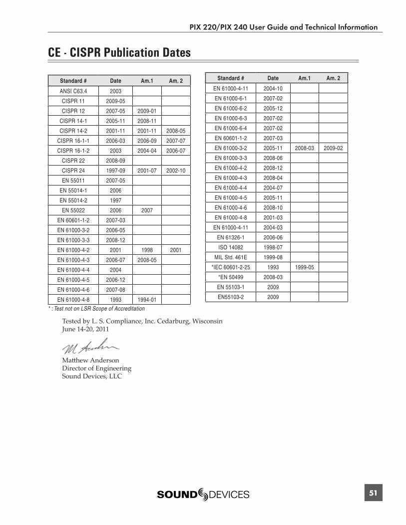
PIX 220/PIX 240 User Guide and Technical Information
51
CE - CISPR Publication Dates
Standard # Date Am.1 Am. 2
ANSI C63.4 2003
CISPR 11 2009-05
CISPR 12 2007-05 2009-01
CISPR 14-1 2005-11 2008-11
CISPR 14-2 2001-11 2001-11 2008-05
CISPR 16-1-1 2006-03 2006-09 2007-07
CISPR 16-1-2 2003 2004-04 2006-07
CISPR 22 2008-09
CISPR 24 1997-09 2001-07 2002-10
EN 55011 2007-05
EN 55014-1 2006
EN 55014-2 1997
EN 55022 2006 2007
EN 60601-1-2 2007-03
EN 61000-3-2 2006-05
EN 61000-3-3 2008-12
EN 61000-4-2 2001 1998 2001
EN 61000-4-3 2006-07 2008-05
EN 61000-4-4 2004
EN 61000-4-5 2006-12
EN 61000-4-6 2007-08
EN 61000-4-8 1993 1994-01
Standard # Date Am.1 Am. 2
EN 61000-4-11 2004-10
EN 61000-6-1 2007-02
EN 61000-6-2 2005-12
EN 61000-6-3 2007-02
EN 61000-6-4 2007-02
EN 60601-1-2 2007-03
EN 61000-3-2 2005-11 2008-03 2009-02
EN 61000-3-3 2008-06
EN 61000-4-2 2008-12
EN 61000-4-3 2008-04
EN 61000-4-4 2004-07
EN 61000-4-5 2005-11
EN 61000-4-6 2008-10
EN 61000-4-8 2001-03
EN 61000-4-11 2004-03
EN 61326-1 2006-06
ISO 14082 1998-07
MIL Std. 461E 1999-08
*IEC 60601-2-25 1993 1999-05
*EN 50499 2008-03
EN 55103-1 2009
EN55103-2 2009
* : Test not on LSR Scope of Accreditation
Tested by L. S. Compliance, Inc. Cedarburg, Wisconsin June 14-20, 2011
Matt hew AndersonDirector of Engineering Sound Devices, LLC

PIX 220/PIX 240 User Guide and Technical Information
v. 2.0 Features and specifications are subject to change. Visit www.sounddevices.com for the latest documentation.
52
Software License End-user license agreement for Sound Devices PIX Recorder Embedded Software / Firmware
Important Read carefully: This Sound Devices, LLC end-user license agreement (“EULA”) is a legal agreement between you (either an individual or a single entity) and Sound Devices, LLC for the Sound Devices, LLC software product identifi ed above, which includes computer software, embedded software, and may include associated media, printed materials, and “online” or electronic documentation (“SOFTWARE PRODUCT”). By using, installing, or copying the SOFTWARE PRODUCT, you agree to be bound by the terms of this EULA. If you do not agree to the terms of this EULA, do not use or install the SOFTWARE PRODUCT.
Software Product License
The SOFTWARE PRODUCT is protected by copyright laws and international copyright treaties, as well as other intellectual property laws and treaties. The SOFTWARE PRODUCT is licensed, not sold.
Grant of license. This EULA grants you the following limited, non-exclusive rights: In consideration of payment of the licensee fee, Sound Devices, LLC, as licensor, grants to you, the licensee, a non-exclusive right to use this copy of a Sound Devices, LLC software program (hereinafter the “SOFTWARE”) on a single product and/or computer. All rights not expressly granted to licensee are reserved to Sound Devices, LLC.
Software ownership. As the licensee, you own the hardware on which the SOFTWARE is recorded or fi xed. Sound Devices, LLC shall retain full and complete title to the SOFTWARE and all subsequent copies of the SOFTWARE, regardless of the media or form on or in which the original copies may exist. The license is not a sale of the original SOFTWARE.
Copyright. All rights, title, and copyrights in and to the SOFTWARE PRODUCT (including, but not limited to, any images, photographs, animations, video, audio, music, text, and “applets” incorporated into the SOFTWARE PRODUCT) and any copies of the SOFTWARE PRODUCT are owned by Sound Devices, LLC or its suppliers. The SOFTWARE PRODUCT is protected by copyright laws and interna-tional treaty provisions. Therefore, you must treat the SOFTWARE PRODUCT like any other copyrighted material, except that you may make copies as only provided below. You may not copy the printed materials accompanying the SOFTWARE PRODUCT.
Restrictions on use. Licensee may not distribute copies of the SOFTWARE or accompanying materials to others. Licensee may not modify, adapt, translate, reverse engineer, decompile, disassemble, or create derivative works based on the SOFTWARE or its accompa-nying printed or written materials.
Transfer restrictions. Licensee shall not assign, rent, lease, sell, sublicense, or otherwise transfer the SOFTWARE to another party with-out prior written consent of Sound Devices, LLC. Any party authorized by Sound Devices, LLC to receive the SOFTWARE must agree to be bound by the terms and conditions of this agreement.
Termination. Without prejudice to any other rights, Sound Devices, LLC may terminate this EULA if you fail to comply with the terms and conditions of this EULA. In such event, you must destroy all copies of the SOFTWARE PRODUCT and all of its component parts.
Limited Warranty
No warranties. Sound Devices, LLC expressly disclaims any warranty for the SOFTWARE PRODUCT. The SOFTWARE PRODUCT and any related documentation is provided “as is” without warranty or condition of any kind, either express or implied, including, without limita-tion, the implied warranties and conditions of merchantability, fi tness for a particular purpose, or non-infringement. The entire risk arising out of use or performance of the SOFTWARE PRODUCT remains with you.
No liability for damages. In no event shall Sound Devices, LLC or its suppliers be liable for any damages whatsoever (including, without limitation, damages for loss of business profi ts, business interruption, loss of business information, or any other pecuniary loss) arising out of the use of or inability to use this Sound Devices, LLC product, even if Sound Devices, LLC has been advised of the possibility of such damages. In any case, Sound Devices, LLC’s entire liability under any provision of this evaluation license shall be limited to the greater of the amount actually paid by you for the SOFTWARE PRODUCT or U.S. $5.00. Because some states/jurisdictions do not allow the exclusion or limitation of liability for consequential or incidental damages, the above limitation may not apply to you.
Governing Law
This agreement and limited warranty are governed by the laws of the state of Wisconsin.

PIX 220/PIX 240 User Guide and Technical Information
53
Warranty and Technical Support
Warranty & Service Sound Devices, LLC warrants the PIX 240 and PIX 220 Portable Video Recorder against defects in materials and workmanship for a period of ONE (1) year from date of original retail purchase. This is a non-transferable warranty that extends only to the original purchaser. Sound Devices, LLC will repair or replace the product at its discretion at no charge. Warranty claims due to severe service conditions will be addressed on an individual basis. THE WARRANTY AND REMEDIES SET FORTH ABOVE ARE EXCLUSIVE. SOUND DEVICES, LLC DISCLAIMS ALL OTHER WAR-RANTIES, EXPRESS OR IMPLIED, INCLUDING WARRANTIES OF MERCHANTABILITY AND FITNESS FOR A PARTICULAR PURPOSE. SOUND DEVICES, LLC IS NOT RESPONSIBLE FOR SPECIAL, INCIDENTAL, OR CONSEQUENTIAL DAMAGES ARISING FROM ANY BREACH OF WARRANTY OR UNDER ANY OTHER LEGAL THEORY. Because some jurisdictions do not permit the exclusion or limitations set forth above, they may not apply in all cases.
For all service, including warranty repair, please contact Sound Devices for an RMA (return mer-chandise authorization) before sending your unit in for repair. Product returned without an RMA number may experience delays in repair. When sending a unit for repair, please do not include ac-cessories, including SSD drives, CF cards, batt eries, power supplies, carry cases, cables, or adapters unless instructed by Sound Devices.
Sound Devices, LLC Service Repair RMA #XXXXX 300 Wengel Drive Reedsburg, WI 53959 USA telephone: (608) 524-0625
Technical Support / Bug Reports For technical support and bug reporting on all Sound Devices products contact:
Sound Devices, LLC E-mail: [email protected] web: www.sounddevices.com/support/ Telephone: +1 (608) 524-0625 / Toll-Free in the U.S.A.: (800) 505-0625 Fax: +1 (608) 524-0655
Sound Devices hosts a user support forum. The URL is:
htt p://forum.sounddevices.com
Sound Devices cannot guarantee that a given computer, software, or operating system confi gura-tion can be used satisfactorily with the PIX recorder based exclusively on the fact that it meets our minimum system requirements.


PIX 220 and PIX 240, v 2.0 - Printed in U.S.A.