pipe expansion and support _ international site for spirax sarco
DESCRIPTION
pipeTRANSCRIPT
International site for Spirax Sarco Tel: (800) 575-0394Fax: (803) 714-2222
http://www.SpiraxSarco.com/us/
You are here: Home Resources Steam Engineering Tutorials Steam DistributionPipe Expansion and Support
Any steam system must be fully supported, able toexpand during operation and sufficiently flexible toallow movement as a result. This tutorial includesadvice on different methods and full calculations.
Use the quick links below to take you to the mainsections of this tutorial:
The printable version of this page hasnow been replaced byThe Steam and Condensate Loop Book
View the complete collection of SteamEngineering Tutorials
Pipe Expansion and Support
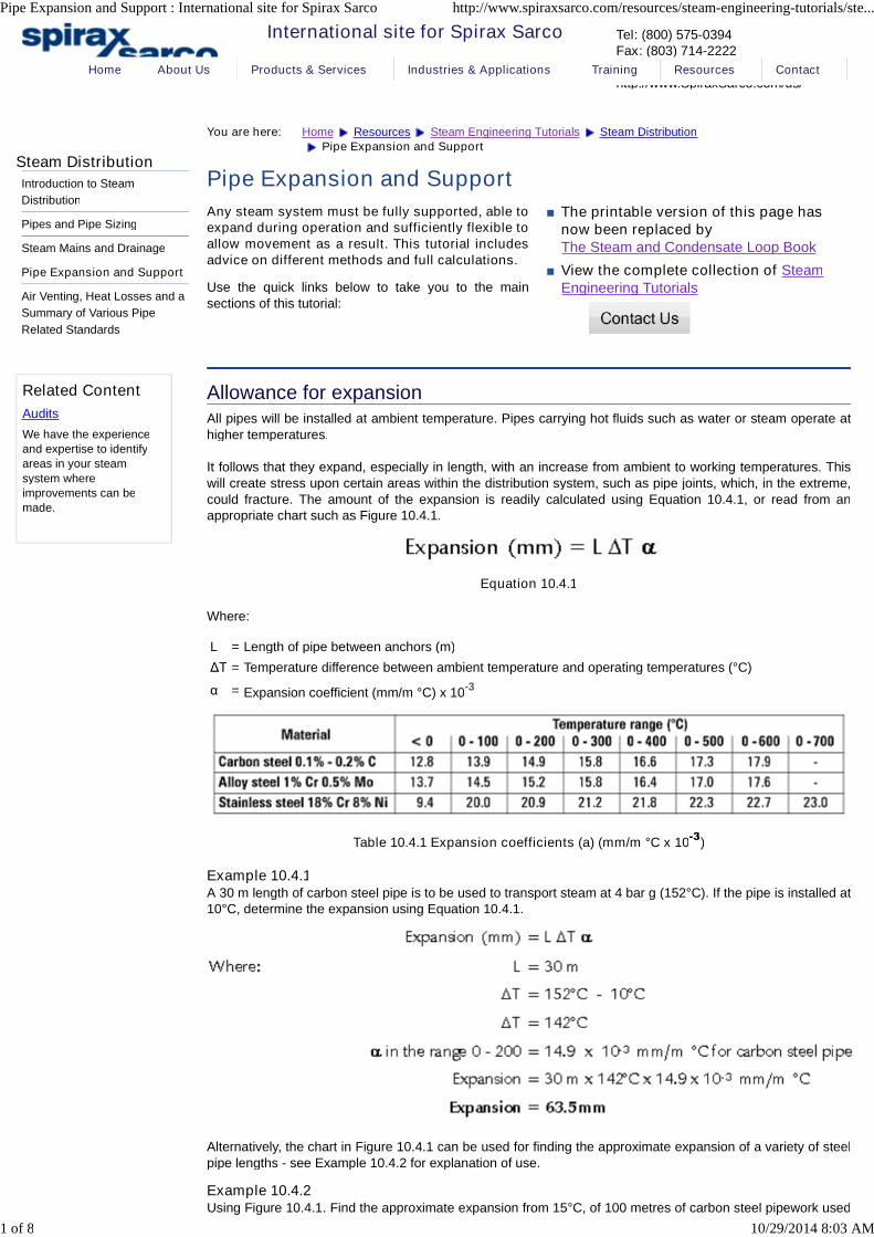
Allowance for expansionAll pipes will be installed at ambient temperature. Pipes carrying hot fluids such as water or steam operate athigher temperatures.
It follows that they expand, especially in length, with an increase from ambient to working temperatures. Thiswill create stress upon certain areas within the distribution system, such as pipe joints, which, in the extreme,could fracture. The amount of the expansion is readily calculated using Equation 10.4.1, or read from anappropriate chart such as Figure 10.4.1.
Equation 10.4.1
Where:
L = Length of pipe between anchors (m)
ΔT = Temperature difference between ambient temperature and operating temperatures (°C)
α = Expansion coefficient (mm/m °C) x 10-3
Table 10.4.1 Expansion coefficients (a) (mm/m °C x 10-3
)
Example 10.4.1A 30 m length of carbon steel pipe is to be used to transport steam at 4 bar g (152°C). If the pipe is installed at10°C, determine the expansion using Equation 10.4.1.
Alternatively, the chart in Figure 10.4.1 can be used for finding the approximate expansion of a variety of steelpipe lengths - see Example 10.4.2 for explanation of use.
Example 10.4.2Using Figure 10.4.1. Find the approximate expansion from 15°C, of 100 metres of carbon steel pipework used
Steam Distribution
Introduction to Steam
Distribution
Pipes and Pipe Sizing
Steam Mains and Drainage
Pipe Expansion and Support
Air Venting, Heat Losses and a
Summary of Various Pipe
Related Standards
Related Content
Audits
We have the experienceand expertise to identifyareas in your steam
system whereimprovements can bemade.
Home About Us Products & Services Industries & Applications Training Resources Contact
Pipe Expansion and Support : International site for Spirax Sarco http://www.spiraxsarco.com/resources/steam-engineering-tutorials/ste...
1 of 8 10/29/2014 8:03 AM

to distribute steam at 265°C.
Temperature difference is 265 - 15°C = 250°C.
Where the diagonal temperature difference line of 250°C cuts the horizontal pipe length line at 100 m, drop avertical line down. For this example an approximate expansion of 330 mm is indicated.
Fig. 10.4.1 A chart showing the expansion in various steel pipe lengths at various temperaturedifferences
Table 10.4.2 Temperature of saturated steam
Pipework flexibilityThe pipework system must be sufficiently flexible to accommodate the movements of the components as theyexpand. In many cases the flexibility of the pipework system, due to the length of the pipe and number ofbends and supports, means that no undue stresses are imposed. In other installations, however, it will benecessary to incorporate some means of achieving this required flexibility.
An example on a typical steam system is the discharge of condensate from a steam mains drain trap into thecondensate return line that runs along the steam line (Figure 10.4.2). Here, the difference between theexpansions of the two pipework systems must be taken into account. The steam main will be operating at ahigher temperature than that of the condensate main, and the two connection points will move relative to eachother during system warm-up.
Fig. 10.4.2 Flexibility in connection to condensate return line
The amount of movement to be taken up by the piping and any device incorporated in it can be reduced by'cold draw'. The total amount of expansion is first calculated for each section between fixed anchor points. Thepipes are left short by half of this amount, and stretched cold by pulling up bolts at a flanged joint, so that atambient temperature, the system is stressed in one direction. When warmed through half of the totaltemperature rise, the piping is unstressed. At working temperature and having fully expanded, the piping isstressed in the opposite direction. The effect is that instead of being stressed from 0 F to +1 F units of force,the piping is stressed from -½ F to + ½ F units of force.
In practical terms, the pipework is assembled cold with a spacer piece, of length equal to half the expansion,
Pipe Expansion and Support : International site for Spirax Sarco http://www.spiraxsarco.com/resources/steam-engineering-tutorials/ste...
2 of 8 10/29/2014 8:03 AM
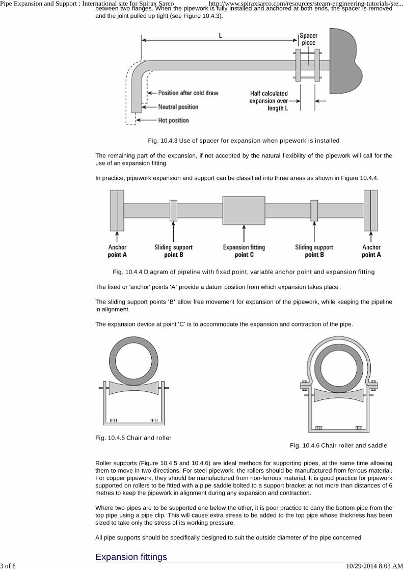
Fig. 10.4.5 Chair and roller
Fig. 10.4.6 Chair roller and saddle
between two flanges. When the pipework is fully installed and anchored at both ends, the spacer is removedand the joint pulled up tight (see Figure 10.4.3).
Fig. 10.4.3 Use of spacer for expansion when pipework is installed
The remaining part of the expansion, if not accepted by the natural flexibility of the pipework will call for theuse of an expansion fitting.
In practice, pipework expansion and support can be classified into three areas as shown in Figure 10.4.4.
Fig. 10.4.4 Diagram of pipeline with fixed point, variable anchor point and expansion fitting
The fixed or 'anchor' points 'A' provide a datum position from which expansion takes place.
The sliding support points 'B' allow free movement for expansion of the pipework, while keeping the pipelinein alignment.
The expansion device at point 'C' is to accommodate the expansion and contraction of the pipe.
Roller supports (Figure 10.4.5 and 10.4.6) are ideal methods for supporting pipes, at the same time allowingthem to move in two directions. For steel pipework, the rollers should be manufactured from ferrous material.For copper pipework, they should be manufactured from non-ferrous material. It is good practice for pipeworksupported on rollers to be fitted with a pipe saddle bolted to a support bracket at not more than distances of 6metres to keep the pipework in alignment during any expansion and contraction.
Where two pipes are to be supported one below the other, it is poor practice to carry the bottom pipe from thetop pipe using a pipe clip. This will cause extra stress to be added to the top pipe whose thickness has beensized to take only the stress of its working pressure.
All pipe supports should be specifically designed to suit the outside diameter of the pipe concerned.
Expansion fittings
Pipe Expansion and Support : International site for Spirax Sarco http://www.spiraxsarco.com/resources/steam-engineering-tutorials/ste...
3 of 8 10/29/2014 8:03 AM
Horseshoe or lyre loop
The expansion fitting ('C' Figure 10.4.4) is one method of accommodating expansion. These fittings areplaced within a line, and are designed to accommodate the expansion, without the total length of the linechanging. They are commonly called expansion bellows, due to the bellows construction of the expansionsleeve.
Other expansion fittings can be made from the pipework itself. This can be a cheaper way to solve theproblem, but more space is needed to accommodate the pipe.
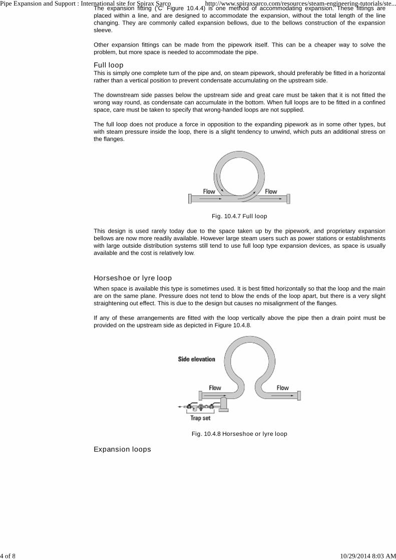
Full loopThis is simply one complete turn of the pipe and, on steam pipework, should preferably be fitted in a horizontalrather than a vertical position to prevent condensate accumulating on the upstream side.
The downstream side passes below the upstream side and great care must be taken that it is not fitted thewrong way round, as condensate can accumulate in the bottom. When full loops are to be fitted in a confinedspace, care must be taken to specify that wrong-handed loops are not supplied.
The full loop does not produce a force in opposition to the expanding pipework as in some other types, butwith steam pressure inside the loop, there is a slight tendency to unwind, which puts an additional stress onthe flanges.
Fig. 10.4.7 Full loop
This design is used rarely today due to the space taken up by the pipework, and proprietary expansionbellows are now more readily available. However large steam users such as power stations or establishmentswith large outside distribution systems still tend to use full loop type expansion devices, as space is usuallyavailable and the cost is relatively low.
When space is available this type is sometimes used. It is best fitted horizontally so that the loop and the mainare on the same plane. Pressure does not tend to blow the ends of the loop apart, but there is a very slightstraightening out effect. This is due to the design but causes no misalignment of the flanges.
If any of these arrangements are fitted with the loop vertically above the pipe then a drain point must beprovided on the upstream side as depicted in Figure 10.4.8.
Fig. 10.4.8 Horseshoe or lyre loop
Expansion loops
Pipe Expansion and Support : International site for Spirax Sarco http://www.spiraxsarco.com/resources/steam-engineering-tutorials/ste...
4 of 8 10/29/2014 8:03 AM
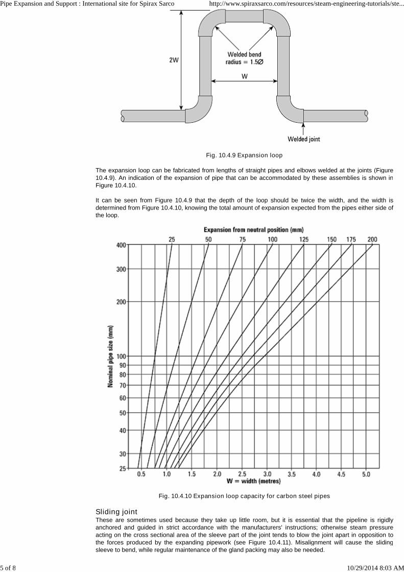
Fig. 10.4.9 Expansion loop
The expansion loop can be fabricated from lengths of straight pipes and elbows welded at the joints (Figure10.4.9). An indication of the expansion of pipe that can be accommodated by these assemblies is shown inFigure 10.4.10.
It can be seen from Figure 10.4.9 that the depth of the loop should be twice the width, and the width isdetermined from Figure 10.4.10, knowing the total amount of expansion expected from the pipes either side ofthe loop.
Fig. 10.4.10 Expansion loop capacity for carbon steel pipes
Sliding jointThese are sometimes used because they take up little room, but it is essential that the pipeline is rigidlyanchored and guided in strict accordance with the manufacturers' instructions; otherwise steam pressureacting on the cross sectional area of the sleeve part of the joint tends to blow the joint apart in opposition tothe forces produced by the expanding pipework (see Figure 10.4.11). Misalignment will cause the slidingsleeve to bend, while regular maintenance of the gland packing may also be needed.
Pipe Expansion and Support : International site for Spirax Sarco http://www.spiraxsarco.com/resources/steam-engineering-tutorials/ste...
5 of 8 10/29/2014 8:03 AM

Fig. 10.4.11 Sliding joint
Expansion bellowsAn expansion bellows, Figures 10.4.12, has the advantage that it requires no packing (as does the sliding jointtype). But it does have the same disadvantages as the sliding joint in that pressure inside tends to extend thefitting, consequently, anchors and guides must be able to withstand this force.
Fig. 10.4.12 Simple expansion bellows
Bellows may incorporate limit rods, which limit over-compression and over-extension of the element. Thesemay have little function under normal operating conditions, as most simple bellows assemblies are able towithstand small lateral and angular movement. However, in the event of anchor failure, they behave as tierods and contain the pressure thrust forces, preventing damage to the unit whilst reducing the possibility offurther damage to piping, equipment and personnel (Figure 10.4.13 (b)).
Where larger forces are expected, some form of additional mechanical reinforcement should be built into thedevice, such as hinged stay bars (Figure 10.4.13 (c)).
There is invariably more than one way to accommodate the relative movement between two laterallydisplaced pipes depending upon the relative positions of bellows anchors and guides. In terms of preference,axial displacement is better than angular, which in turn, is better than lateral. Angular and lateral movementshould be avoided wherever possible.
Figure 10.4.13 (a), (b), and (c) give a rough indication of the effects of these movements, but, under allcircumstances, it is highly recommended that expert advice is sought from the bellows' manufacturerregarding any installation of expansion bellows.
Pipe Expansion and Support : International site for Spirax Sarco http://www.spiraxsarco.com/resources/steam-engineering-tutorials/ste...
6 of 8 10/29/2014 8:03 AM

Fig. 10.4.13 (a) Axial movement of bellows
Fig. 10.4.13 (b) Lateral and angular movement of bellows
Fig. 10.4.13 (c) Angular and axial movement of bellows
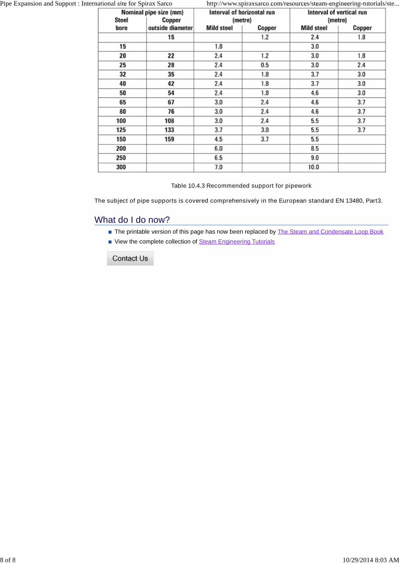
Pipe support spacingThe frequency of pipe supports will vary according to the bore of the pipe; the actual pipe material (i.e. steel orcopper); and whether the pipe is horizontal or vertical.
Some practical points worthy of consideration are as follows:
Pipe supports should be provided at intervals not greater than shown in Table 10.4.3, and run alongthose parts of buildings and structures where appropriate supports may be mounted.
Where two or more pipes are supported on a common bracket, the spacing between the supportsshould be that for the smallest pipe.
When an appreciable movement will occur, i.e. where straight pipes are greater than 15 metres inlength, the supports should be of the roller type as outlined previously.
Vertical pipes should be adequately supported at the base, to withstand the total weight of the verticalpipe and the fluid within it. Branches from vertical pipes must not be used as a means of support forthe pipe, because this will place undue strain upon the tee joint.
All pipe supports should be specifically designed to suit the outside diameter of the pipe concerned.The use of oversized pipe brackets is not good practice.
Table 10.4.3 can be used as a guide when calculating the distance between pipe supports for steel andcopper pipework.
Pipe Expansion and Support : International site for Spirax Sarco http://www.spiraxsarco.com/resources/steam-engineering-tutorials/ste...
7 of 8 10/29/2014 8:03 AM
The printable version of this page has now been replaced by The Steam and Condensate Loop Book
View the complete collection of Steam Engineering Tutorials
Table 10.4.3 Recommended support for pipework
The subject of pipe supports is covered comprehensively in the European standard EN 13480, Part3.
What do I do now?
Pipe Expansion and Support : International site for Spirax Sarco http://www.spiraxsarco.com/resources/steam-engineering-tutorials/ste...
8 of 8 10/29/2014 8:03 AM