piezo steering mirrors & phase shifters - nanopositioning · piezo steering mirrors & phase...
TRANSCRIPT

Piezo Steering Mirrors & Phase ShiftersFor Photonics, Aerospace, Telecommunication, Medical
FAST
PREC ISE
IND IV IDUAL
W W W . P I . W S

Piezo Tip/Tilt-Mirrors: Nanopositioning Platforms
The S-323 Z/tip/tilt platform integrates capacitive feedback sensors for highest resolution and stability
S-310.10 & S-316.10 phase shifter / tripod optics scanner & alignment systems
S-340 tip/tilt platform for mirrors up to 4” diameter
S-303 closed-loop and open loop high resolution phase shifters
P-528 Tip/tilt & Z piezo platform with aperture
S-224 Small piezo tip/tilt mirror for high-speed beam steering tasks & image stabilization applications
S-334 Long Travel (120 mrad) 2-axis Tip-tilt platform with closed-loop control
S-330 tip-tilt platforms with closed-loop control
S-330 3-axis tip-tilt + piston platform with closed-loop control
Click on the Images to Jump to Datasheet

S-323 Piezo Z/Tip/Tilt PlatformHigh Dynamics & Stability Nanopositioning System with Direct Metrology
� Optical Beam Deflection to 6 mrad
� Sub-μrad Resolution for High Positioning Stability
� Position Servo-Control with Capacitive Sensors
� Frictionless, High-Precision Flexure Guiding System
� System Combination with Digital Controllers for Highest Li-
nearity
S-303 Piezo Phase ShifterHighest Dynamics and Stability with Capacitive Feedback Sensor
� 25 kHz Resonant Frequency for Sub-Millisecond Dynamics
� Capacitive Sensor Option for Highest Linearity and Stability
� 3 μm Travel Range
� Compact Size: 30 mm Diameter x 10 mm
� Aperture with Open-Loop Versions
� Invar Option for Highest Thermal Stability
S-224 – S-226 Piezo Tilt-MirrorFast Steering Mirror Combines Highest Dynamics and Compact Design
� Optical Beam Deflection to 4.4 mrad
� Sub-μrad Resolution, Sub-Millisecond Response
� Frictionless, High-Precision Flexure Guiding System
� Includes BK7 Mirror
� Optional Position Feedback Sensor
� Outstanding Lifetime Due to PICMA® Piezo Actuators
S-303 closed-loop model (left) and open-loopmodel (right). DIP switch for size comparison
S-224 Piezo tip/tilt mirror for high-speed beam stee-ring tasks and image stabilization applications
Model Active Travel range Resolution Unloaded resonant
axes frequency
S-323.3CD Z, θX, θY 30 µm, ±1.5 mrad 0.1 nm, ±0.05 µrad 1.7 kHz
Model Active Closed-loop/ Closed-loop/ Unloaded
axes open-loop travel open-loop resonant
@ -20 to +120V resolution frequency
S-303.CD (closed-loop)/ Z 2 / 3 µm 0.03 nm 25 kHzS-302.0L (open-loop)
Model Active Open-loop tilt Closed-loop/ Unloaded
axes angle @ 0 to +100V open-loop resonant
The S-323 Z/tip/tilt platform integrates capacitivesensors for highest resolution and stability

© P
hys
ik In
stru
men
te (
PI)
Gm
bH
& C
o. K
G 2
008.
Su
bje
ct t
o c
han
ge
wit
ho
ut
no
tice
. All
dat
a ar
e su
per
sed
ed b
y an
y n
ew r
elea
se.
Th
e n
ewes
t re
leas
e fo
r d
ata
shee
ts is
ava
ilab
le f
or
do
wn
load
at
ww
w.p
i.ws.
Cat
120E
Insp
irat
ion
s200
9 08
/10.
18
High-Dynamics with Large Clear Aperture
P-518, P-528, P-558 Piezo Z/Tip/Tilt Stage
P-5x8 series, Z/tip/tilt nanoposi-tioners / scanners are open-frame, high-resolution, piezo-driven stages providing mo tionto 240 µm and 2.4 mrad withresolutions of up to 0.5 nm and 50 nrad. The 66 x 66 mm clear aperture isideal for transmitted-lightapplications.
XY and XYZ multi-axis ver -sions in the same form factor
are also offered as P-517, P-527(see p. 2-70) models with sixdegrees of freedom are avail-able upon request.
Capacitive Position Sensors
for Higher Accuracy
PI's proprietary capacitive sen-sors measure position directlyand without physical contact.
They are free of friction and hy -steresis, a fact which, in com bi-nation with the positioning res-olution of well under 1 nm,makes it possible to achievevery high levels of linearity . Afurther advantage of directmetrology with capacitive sen-sors is the high phase fidelityand the high bandwidth of upto 10 kHz.
Excellent Guiding Accuracy
Flexures optimized with FiniteElement Analysis (FEA) areused to guide the stage. FEAtechniques are used to give thedesign the highest possiblestiffness in, and perpendicularto, the direction of motion, andto minimize linear and angularrunout. Flexures allow extre -mely high-precision motion, nomatter how minute, as they arecompletely free of play andfriction.
Flatness and Straightness isfurther enhanced by active tra-jectory control: Multi-axisnano positioning systems equi -p ped with both parallel kine-matics and parallel direct me -trology are able to measureplatform position in all degreesof freedom against one com-mon fixed reference. In such
systems, undesirable motionfrom one actuator in the direc-tion of another (cross-talk) isdetected immediately and ac -tively compensated by theservo-loops. This Active T ra -jectory Control Concept cankeep deviation from a trajecto-ry to under a few nanometers,even in dynamic operation.
Higher Precision in Periodic
Motion
The highest dynamic accuracyin scanning applications is
Application Examples
� Metrology
� Interferometry
� Optics
� Lithography
� Scanning microscopy
� Mass storage device testing
� Laser technology
� Micromachining
P-528 Z/tip/tilt piezo nanopositioning system
� 1- and 3-Axis Versions
� Closed-Loop Vertical / Tilt Range to 200 µm / 2 mrad
(Open-Loop to 240 / 2.4)
� Parallel Kinematics / Metrology for Enhanced
Responsiveness & Multi-Axis Precision
� Frictionless, High-Precision Flexure Guiding System
� Outstanding Lifetime Due to PICMA® Piezo Actuators
� Clear Aperture 66 x 66 mm
� Capacitive Sensors for Highest Linearity
Ordering Information
P-558.ZCD
Precision Nanopositioning Z-Stage,50 µm, Direct Metrology, CapacitiveSensors, Sub-D Connector
P-558.ZCL
Precision Nanopositioning Z-Stage,50 µm, Direct Metrology, CapacitiveSensors, LEMO Connector
P-518.ZCD
Precision Nanopositioning Z-Stage,100 µm, Direct Metrology,Capacitive Sensors, Sub-DConnector
P-518.ZCL
Precision Nanopositioning Z-Stage,100 µm, Direct Metrology,Capacitive Sensors, LEMOConnector
P-528.ZCD
Precision Nanopositioning Z-Stage,200 µm, Direct Metrology,Capacitive Sensors, Sub-DConnector
P-528.ZCL
Precision Nanopositioning Z-Stage,200 µm, Direct Metrology,Capacitive Sensors, LEMOConnector
P-558.TCD
Precision Nanopositioning Z/Tip/TiltStage, 50 µm, 0.6 mrad, ParallelMetrology, Capacitive Sensors,Sub-D Connector
P-518.TCD
Precision Nanopositioning Z/Tip/TiltStage, 100 µm, 1.4 mrad, ParallelMetrology, Capacitive Sensors,Sub-D Connector
P-528.TCD
Precision Nanopositioning Z/Tip/TiltStage, 200 µm, 2.4 mrad, ParallelMetrology, Capacitive Sensors,Sub-D Connector
P-558, P-518, P-528 dimensions in mm

Technical Data
Model P-558.ZCD/ P-558.TCD P-518.ZCD/ P-518.TCD P-528.ZCD/ P-528.TCD Units Tolerance
P-558.ZCL P-518.ZCL P-528.ZCL
Active axes Z Z, �x, �y Z Z, �x, �y Z Z, �x, �y
Motion and positioning
Integrated sensor Capacitive Capacitive Capacitive Capacitive Capacitive Capacitive
Open-loop travel, -20 to +120 V 60 60 140 140 240 240 µm min.
(+20 %/-0 %)
Open-loop tip/tilt angle, -20 to +120 V – ±0.3 mrad – ±0.7 mrad – ±1.2 mrad mrad min. (+20 %/-0 %)
Closed-loop travel 50 50 100 100 200 200 µm
Closed-loop tip/tilt angle – ±0.25 mrad - ±0.5 mrad – ±1 mrad mrad
Open-loop resolution 0.2 0.2 0.2 0.4 0.6 0.6 nm typ.
Open-loop tip/tilt angle resolution – 0.02 – 0.04 – 0.06 µrad typ.
Closed-loop resolution 0.5 0.5 0.8 0.8 1 1 nm typ.
Closed-loop tip/tilt resolution – 0.05 – 0.05 – 0.1 µrad typ.
Linearity �x, �y – 0.03 – 0.03 – 0.03 % typ.
Repeatability ±5 ±5 ±5 ±5 ±10 ±10 nm typ.
Repeatability �x, �y – ±0.03 – ±0.05 – ±0.1 µrad typ.
Runout �z (Z motion) <10 <10 <10 <10 <20 <20 µrad typ.
Runout �x, �y (Z motion) <50 <50 <50 <50 <100 <100 µrad typ.
Mechanical properties
Stiffness 4 4 2.7 2.7 1.5 1.5 N/µm ±20 %
Unloaded resonant frequency (Z) 570 570 500 500 350 350 Hz ±20 %
Unloaded resonant frequency (�x, �y) - 610 - 530 - 390 Hz ±20 %
Resonant frequency @ 30 g in Z 410 410 350 350 210 210 Hz ±20 %
Resonant frequency @ 500 g in X, Y - 430 - 370 - 250 Hz ±20 %
Resonant frequency @2500 g in Z 245 245 200 200 130 130 Hz ±20 %
Resonant frequency @ 2500 g �x, �y - 240 - 190 - 115 Hz ±20 %
Push/pull force capacity 100 / 50 100 / 50 100 / 50 100 / 50 100 / 50 100 / 50 N Max.
Drive properties
Ceramic type PICMA® PICMA® PICMA® PICMA® PICMA® PICMA®
P-885 P-885 P-885 P-885 P-885 P-885
Electrical capacitance 6 6 8.4 8.4 14.8 14.8 µF ±20 %
Dynamic operating current coefficient 15 15 10.5 10.5 9.2 9.2 µA/ ±20%(Hz•µm)
Miscellaneous
Operating temperature range -20 to 80 -20 to 80 -20 to 80 -20 to 80 -20 to 80 -20 to 80 °C
Material Aluminum Aluminum Aluminum Aluminum Aluminum Aluminum
Dimensions 150x150x30 150x150x30 150x150x30 150x150x30 150x150x30 150x150x30 mm
Mass 1380 1380 1400 1400 1420 1420 g ±5 %
Cable length 1.5 1.5 1.5 1.5 1.5 1.5 m ±10 mm
Sensor / voltage connection CD-version: Sub-D CD-version: Sub-D CD-version: Sub-D
Sub-D special Special Sub-D special Special Sub-D special Special
CL-version: CL-version: CL-version:
LEMO LEMO LEMO
Resolution of PI Piezo Nanopositioners is not limited by friction or stiction. V alue given is noise equivalent motion with E-50 3 (p. 2-146) or E-710 controller (p. 2-128)Recommended controllerCD-Versions: Single-channel (1 per axis): E-610 servo controller / amplifier (p. 2-110), E-625 servo controller , bench-top (p. 2-114)Single-channel digital controller: E-753 (bench-top) (p. 2-108)CL-Versions: Single-channel: E-500 modular piezo controller system (p. 2-142) with E-505 (p. 2-147) high-power amplifier module and E-509 servo-controller (p. 2-152)Multi-channel versions: Multi-channel digital controllers: E-710 bench-top (p. 2-128), E-712 modular (p. 2-140), E-725 high-power (p. 2-126), E-761 PCI board (p. 2-130)
made possible by the DDLalgorithm, which is available inPI's modern digital controllers.DDL eliminates tracking errors,improving dynamic linearityand usable bandwidth by up tothree orders of magnitude!
Ceramic Insulated Piezo Actu -
ators Provide Long Lifetime
Highest possible reliability isassured by the use of award-winning PICMA® multilayerpiezo actuators. PICMA® actua-tors are the only actuators on
the market with ceramic-onlyinsulation, which makes themresistant to ambient humidityand leakage-current failures.They are thus far superior toconventional actuators in relia-bility and lifetime.

� Sub-µrad Resolution
� Sub-Millisecond Response
� Up to 4.4 mrad Optical Beam Deflection
� Closed-Loop Versions for Better Linearity
� Includes BK7 Mirror
� Zero Friction Flexure Guiding System
High-Speed Miniature Piezo Tilt Mirror
S-224 Tilt Mirror
S-224 · S-226
S-224, S-226 dimensions (in mm)
Application Examples
� Laser beam steering &scanning
� Beam switching
� Correction of polygonscanner errors
� Laser beam stabilization
S-224/S-226 miniature tilt plat-forms are extremely fast andcompact tilt units, providing atilt range of 2.2 mrad and sub-millisecond response. The S-224 and S-226 are deliveredwith a Ø 15 x 4 mm BK7 glassmirror.
Open- and Closed-Loop
Operation
The S-224 is specifically de-signed for open-loop opera-tion. The S-226 closed-loopversion is available for highestaccuracy and repeatability . Inopen-loop operation, the plat-form’s angular position isroughly proportional to thedrive voltage (see page 4-17 inthe “Tutorial” section for be-
havior of open-loop piezos).Open-loop operation is idealfor applications where theposition is controlled by dataprovided by an external opticalsensor, a CCD camera, etc.
The closed-loop version (S-226) allows absolute posi-
tion control, high linearity, andrepeatability based on theinternal ultra-high-resolutionfeedback sensor.
Working Principle / Lifetime
S-224/S-226 miniature tilt plat-forms are equipped with long-life, ceramic-encapsulated, high-performance PICMA® piezodrives pushing a frictionless,flexure-mounted platform. Theflexure is FEA (finite elementanalysis) modeled for zero stic-tion, zero friction and excep-tional guiding precision; it alsoserves as the pivot point andpreload for the piezo actuator.
Since drives and guides arefrictionless and not subject towear and tear, these units offeran exceptionally high level ofreliability.
Ordering Information
S-224.00
Piezo Tilt Platform 2.2 mrad (4.4 mrad optical) with Mirror,Open-Loop
S-226.00
Piezo Tilt Platform 2.0 mrad (4.4 mrad optical) with Mirror,Closed-Loop
Ask about custom designs!
3-14
Notes
See the “Selection Guide” on p. 3-8 for comparison withother steering mirrors.
See “Piezo Drivers & Nanopo-sitioning Controllers” sectionfor our comprehensive line oflow-noise modular and OEM
control electronics for com-puter and manual control.
© P
I 199
8-20
05. S
ub
ject
to
ch
ang
e w
/o n
oti
ce. C
at 1
18 0
5/09
.17

Technical Data
Models S-224.00 S-226.00 Units Notes see page 3-26
Active axes �X �X
* Open-loop tilt angle @ 0 to 100 V 2.2 2.2 mrad ±20% A2
* Closed-loop tilt angle - 2.0 mrad A3
Integrated feedback sensor - strain gauge B
** Closed-loop / open-loop resolution - / 0.05 0.1 / 0.05 µrad C1
Closed-loop linearity (typ.) - 0.2 %
Full-range repeatability (typ.) - ±3 µrad C3
Electrical capacitance 1.5 1.5 µF ±20% F1
*** Dynamic operating current coefficient (DOCC) 0.1 0.1 µA/(Hz x µrad) F2
Unloaded resonant frequency (f0) 9.0 9.0 kHz ±20% G2
Resonant frequency 7.5 7.5 kHz ±20% G3w/ ø 15 x 4 mm glass mirror (included)
Resonant frequency 5.7 5.7 kHz ±20% G3w/ ø 15 x 4 mm copper mirror
Distance, pivot point to platform surface (T) 4 4 mm
Platform moment of inertia 215 215 g · mm2
Operating temperature range - 20 to 80 - 20 to 80 °C H2
Voltage connection VL VL J1
Sensor connection - L J2
Weight (w/o cables) 98 98 g ±5%
Material (case / platform) N-S / N-S N-S / N-S L
Recommended amplifier / controller G, C H, D(codes explained page 3-9)
* Mechanical tilt, opticalbeam deflection is twice as large.
** For calibration informationsee p. 3-7.Resolution of PZT tip/tiltplatforms is not limited by friction or stiction. Noise equivalent motionwith E-503 amplifier.
*** Dynamic Operating CurrentCoefficient in µA per Hz andµrad. Example: Sinusoidalscan of 100 µrad at 10 Hzrequires approximately 0.1 mA drive current.
3-15

©P
hys
ikIn
stru
men
te(P
I)G
mb
H&
Co
.KG
2008
.Su
bje
ctto
chan
ge
wit
ho
ut
no
tice
.All
dat
aar
esu
per
sed
edb
yan
yn
ewre
leas
e.T
he
new
est
rele
ase
for
dat
ash
eets
isav
aila
ble
for
do
wn
load
atw
ww
.pi.w
s.R
110
/04/
07.0
S-334 Tip/Tilt Mirror System / Scanner ProvidesOptical Deflection Angle up to 120 mrad
Fast Steering Mirror with up to 120 mrad Deflection
S-334 dimensions in mm
� Miniature Design
� Optical Beam Deflection to 120 mrad (~ 6.8°)
� Coplanar Axes & Fixed Pivot Point;
Eliminate Polarization Rotation
� Factory Installed Mirror
� Millisecond Response, Resolution to 0.2 μrad
� Closed-loop Position Servo-Control for High Accuracy
� For Mirrors up to 12.5 mm (0.5”) Diameter
� Frictionless, High-Precision Flexure Guiding System
� Parallel Kinematics for Enhanced Dynamics and Better
Multi-Axis Accuracy
S-334 piezo tip/tilt mirrors /scanners provide extremelylarge deflection angles in aminiaturized package. Thesefast steering mirror systemsare based on a sophisticatedparallel-kinematics design with
two coplanar, orthogonal axesand a fixed pivot point.
Large Tip/Tilt Ranges with
Excellent Motion Characteristics
The novel flexure/lever designwith minimized inertia allows
for the exceptionally large tip/tilt range of 60 mrad (50 mradin closed-loop operation, whichis equivalent to 100 mrad opti-cal beam deflection) and veryfast response in the millisecondrange. These parameters makethe system unique in the mar-ket of piezo driven tip/tilt mirrorsystems.
Sub-Microradian Resolution
In addition to the large anglesand the high dynamics theS-334 provides sub-micro-radian resolution. The integrat-ed high-resolution, full-bridgestrain gauge sensors (SGS)provide absolute position con-trol, excellent repeatability andhigh linearity, typically betterthan 0.05 % over the entire trav-el range.
Differential Drive for Improved
Stability and Dynamics
The S-334 is based on a paral-lel-kinematics design with co-planar axes and a single mov-ing platform. Two pairs of dif-ferentially-driven piezo actua-tors are employed to providethe highest dynamics and posi-tion stability over a wide tem-perature range.
Compared to stacked, (two-stage), piezo or galvo scanners,the single-platform design pro-vides several advantages:smaller package size, identical
dynamic performance in bothaxes, faster response and bet-ter linearity. It also preventspolarization rotation.
High Reliability and Long
Lifetime
The compact S-334 systemsare equipped with preloadedPICMA® high-performance pie-zo actuators which are integrat-ed into a sophisticated, FEA-modeled, flexure guiding sys-tem. The PICMA® actuators fea-ture cofired ceramic encapsula-tion and provide better per-formance and reliability thanconventional piezo actuators.Actuators, guidance and sen-sors are maintenance-free, notsubject to wear and offerextraordinary reliability.
Ordering Information
S-334.1SD
High-Dynamics Piezo Tip/TiltPlatform, 25 mrad, SGS, Sub-DConnector, incl. Mirror
S-334.1SL
High-Dynamics Piezo Tip/TiltPlatform, 25 mrad, SGS, LEMOConnector, incl. Mirror
S-334.2SD
High-Dynamics Piezo Tip/TiltPlatform, 50 mrad, SGS, Sub-DConnector, incl. Mirror
S-334.2SL
High-Dynamics Piezo Tip/TiltPlatform, 50 mrad, SGS, LEMOConnector, incl. Mirror
Application Examples
� Image processing /stablilization
� Interlacing, dithering
� Laser scanning /beam steering
� Optics
� Optical filters / switches
� Scanning microscopy
� Beam stabilization
S-334 Piezo Tip/Tilt Platform with Mirror

S-334.2SL cable configuration
Technical Data
Model S-334.1SL S-334.2SL Units Tolerance
S-334.1SD S-334.2SD
Active Axes �X, �Y �X, �Y
Motion and positioning
Integrated sensor SGS SGS
*Open-loop tilt angle at -20 to +120 V 30 60 mrad min. (+20 %/-0 %)
*Closed-loop tilt angle 25 50 mrad
Open-loop resolution 0.2 0.5 µrad typ.
Closed-loop resolution 1 5 µrad typ.
Linearity 0.05 0.05 % typ.
Repeatability 2 5 µrad typ.
Mechanical properties
Resonant frequency underload 3.0 1.0 kHz ±20 %(with standard mirrors)
Load capacity 0.2 0.2 N Max.
Distance of pivot point to platform surface 6 6 mm ±1 mm
Platform moment of inertia 1530 1530 g • mm² ±20 %
Standard mirror (mounted) diameter: 10 mm, diameter: 10 mm,thickness: 2 mm; thickness: 2 mm;BK7, λ/5, R > 98 % BK7, λ/5, R > 98 %(λ = 500 nm to 2 µm) (λ = 500 nm to 2 µm)
Drive properties
Ceramic type PICMA® P-885 PICMA® P-885
Electrical capacitance per axis 3 3 µF ±20 %
Miscellaneous
Operating temperature range -20 to 80 -20 to 80 °C
Material casing Titanium Titanium
Mass 0.065 0.065 kg ±5 %
Cable length 2 2 m ±10 mm
Sensor / voltage connection LEMO connector / LEMO connector /
25-pin sub-D connector 25-pin sub-D connector
Recommended controller / amplifierClosed-loop versions with D-sub connector: E-616 controller for tip/tilt mirror systems (p. 2-132);Open-loop versions with LEMO connector: Modular piezo controller system E-500 (p. 2-142) with amplifier module E-503.00S (three channels) (p. 2-146)or 1 x E-505.00S and 2 x E-505 (high speed applications) (p. 2-147) and E-509 servo controller (p. 2-152 / 3-16)Open-loop: E-663 three channel amplifier (p. 2-136)
Resolution of PI piezo tip/tilt platforms is not limited by friction or stiction. Noise equivalent motion with E-503 amplifier, (p. 2-146).
*Mechanical tilt, optical beam deflection is 120 mrad (open loop) and 100 mrad (closed-loop), respectively.
Factory Installed Mirror
The S-334 is equipped with afactory-installed mirror 10 mm
in diameter and 2 mm thick(flatness λ/5, reflectivity >98 %from 500 nm to 2 µm).
©P
hys
ikIn
stru
men
te(P
I)G
mb
H&
Co
.KG
2008
.Su
bje
ctto
chan
ge
wit
ho
ut
no
tice
.All
dat
aar
esu
per
sed
edb
yan
yn
ewre
leas
e.T
he
new
est
rele
ase
for
dat
ash
eets
isav
aila
ble
for
do
wn
load
atw
ww
.pi.w
s.C
at12
0EIn
spir
atio
ns2
009
08/1
0.18
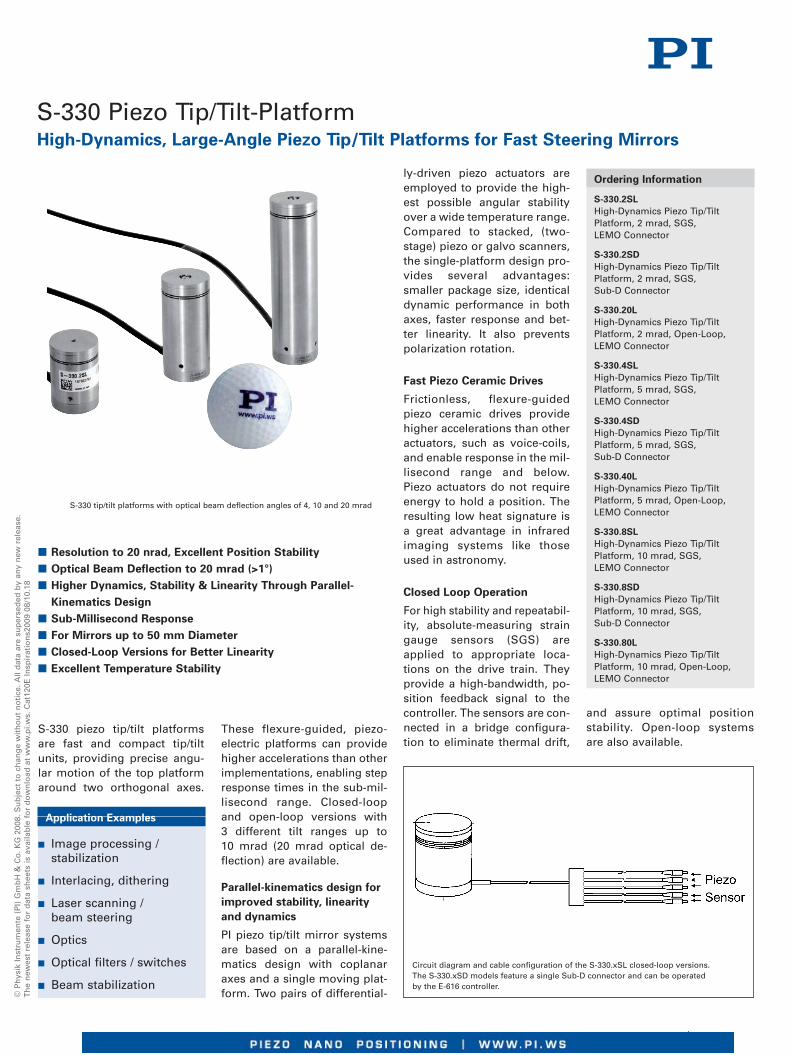
S-330 Piezo Tip/Tilt-Platform
S-330 tip/tilt platforms with optical beam deflection angles of 4, 10 and 20 mrad
S-330 piezo tip/tilt platformsare fast and compact tip/tiltunits, providing precise angu-lar motion of the top platformaround two orthogonal axes.
These flexure-guided, piezo-electric platforms can providehigher accelerations than otherimplementations, enabling stepresponse times in the sub-mil-lisecond range. Closed-loopand open-loop versions with3 different tilt ranges up to10 mrad (20 mrad optical de-flection) are available.
Parallel-kinematics design forimproved stability, linearityand dynamics
PI piezo tip/tilt mirror systemsare based on a parallel-kine-matics design with coplanaraxes and a single moving plat-form. Two pairs of differential-
ly-driven piezo actuators areemployed to provide the high-est possible angular stabilityover a wide temperature range.Compared to stacked, (two-stage) piezo or galvo scanners,the single-platform design pro-vides several advantages:smaller package size, identicaldynamic performance in bothaxes, faster response and bet-ter linearity. It also preventspolarization rotation.
Fast Piezo Ceramic Drives
Frictionless, flexure-guidedpiezo ceramic drives providehigher accelerations than otheractuators, such as voice-coils,and enable response in the mil-lisecond range and below.Piezo actuators do not requireenergy to hold a position. Theresulting low heat signature isa great advantage in infraredimaging systems like thoseused in astronomy.
Closed Loop Operation
For high stability and repeatabil-ity, absolute-measuring straingauge sensors (SGS) areapplied to appropriate loca-tions on the drive train. Theyprovide a high-bandwidth, po-sition feedback signal to thecontroller. The sensors are con-nected in a bridge configura-tion to eliminate thermal drift,
High-Dynamics, Large-Angle Piezo Tip/Tilt Platforms for Fast Steering Mirrors
Circuit diagram and cable configuration of the S-330.xSL closed-loop versions.The S-330.xSD models feature a single Sub-D connector and can be operatedby the E-616 controller.
� Resolution to 20 nrad, Excellent Position Stability� Optical Beam Deflection to 20 mrad (>1°)� Higher Dynamics, Stability & Linearity Through Parallel-Kinematics Design
� Sub-Millisecond Response� For Mirrors up to 50 mm Diameter� Closed-Loop Versions for Better Linearity� Excellent Temperature Stability
Application Examples
� Image processing /stabilization
� Interlacing, dithering
� Laser scanning /beam steering
� Optics
� Optical filters / switches
� Beam stabilization
Ordering Information
S-330.2SLHigh-Dynamics Piezo Tip/TiltPlatform, 2 mrad, SGS,LEMO Connector
S-330.2SDHigh-Dynamics Piezo Tip/TiltPlatform, 2 mrad, SGS,Sub-D Connector
S-330.20LHigh-Dynamics Piezo Tip/TiltPlatform, 2 mrad, Open-Loop,LEMO Connector
S-330.4SLHigh-Dynamics Piezo Tip/TiltPlatform, 5 mrad, SGS,LEMO Connector
S-330.4SDHigh-Dynamics Piezo Tip/TiltPlatform, 5 mrad, SGS,Sub-D Connector
S-330.40LHigh-Dynamics Piezo Tip/TiltPlatform, 5 mrad, Open-Loop,LEMO Connector
S-330.8SLHigh-Dynamics Piezo Tip/TiltPlatform, 10 mrad, SGS,LEMO Connector
S-330.8SDHigh-Dynamics Piezo Tip/TiltPlatform, 10 mrad, SGS,Sub-D Connector
S-330.80LHigh-Dynamics Piezo Tip/TiltPlatform, 10 mrad, Open-Loop,LEMO Connector
and assure optimal positionstability. Open-loop systemsare also available.

Technical Data
Model S-330.2SL S-330.4SL S-330.8SL S-330.2SD S-330.20L Units ToleranceS-330.4SD S-330.40LS-330.8SD S-330.80L
Active axes �X, �Y �X, �Y �X, �Y �X, �Y �X, �Y
Motion and positioning
Integrated sensor SGS SGS SGS SGS –
Open-loop tip/tilt angle, -20 to +120 V 3.5 7 15 as SL version as SL version mrad min.
Closed-loop tip/tilt angle 2 5 10 as SL version – mrad
Open-loop tip/tilt angle resolution 0.02 0.1 0.2 as SL version as SL version µrad typ.
Closed-loop tip/tilt resolution 0.05 0.25 0.5 as SL version – µrad typ.
Linearity in �X, �Y 0.1 0.2 0.25 as SL version – % typ.
Repeatability �X, �Y 0.15 0.5 1 as SL version – µrad typ.
Mechanical properties
Unloaded resonant frequency (�X, �Y) 3.7 3.3 3.1 as SL version as SL version kHz ±20%
Resonant frequency loaded in �X, �Y 2.6 1.6 1.0 as SL version as SL version kHz ±20%(with 25 x 8 mm glass mirror)
Distance of pivot point to platform surface 6 6 6 6 6 mm ±1 mm
Platform moment of inertia 1530 1530 1530 1530 1530 g x mm2 ±20 %
Drive properties
Ceramic type PICMA® PICMA® PICMA® PICMA® PICMA®
Electrical capacitance 3/axis 6/axis 12.5/axis as SL as SL µF ±20%
Dynamic operating current coefficient 0.22/axis 0.4/axis 0.8/axis as SL as SL µA//Hz • mrad) ±20%
Miscellaneous
Operating temperature range -20 to 80 -20 to 80 -20 to 80 -20 to 80 -20 to 80 °C
Material case Stainless steel Stainless steel Stainless steel Stainless steel Stainless steel
Material platform Invar Invar Invar Invar Invar
Mass 0.2 0.38 0.7 as SL version as SL version kg ±5%
Cable length 1.5 1.5 1.5 1.5 1.5 m ±10 mm
Sensor / voltage connection LEMO LEMO LEMO Sub-D connector LEMO
Recommended controller / amplifier
Versions with LEMO connector: modular piezo controller system E-500 (p. 2-142) with amplifier module E-503.00S (three channels) (p. 2-146)
or 1 x E-505.00S and 2 x E-505 (high speed applications) (p. 2-147) and E-509 controller (p. 2-152) (optional)
Open-loop: E-663 three channel amplifier (p. 2-136)
Versions with Sub-D connectors: E-616 servo controller for tip/tilt mirror systems (p. 2-132)
S-330 dimensions in mm
Ceramic Insulated PiezoActuators Provide LongLifetime
Highest possible reliability isassured by the use of award-winning PICMA® multilayerpiezo actuators. PICMA® actua-tors are the only actuators onthe market with ceramic-onlyinsulation, which makes themresistant to ambient humidityand leakage-current failures.They are thus far superior toconventional actuators in relia-bility and lifetime.

© P
hys
ik In
stru
men
te (
PI)
Gm
bH
& C
o. K
G 2
008.
Su
bje
ct t
o c
han
ge
wit
ho
ut
no
tice
. All
dat
a ar
e su
per
sed
ed b
y an
y n
ew r
elea
se.
Th
e n
ewes
t re
leas
e fo
r d
ata
shee
ts is
ava
ilab
le f
or
do
wn
load
at
ww
w.p
i.ws.
Cat
120E
Insp
irat
ion
s200
9 08
/10.
18
S-325 cable configuration (top: S-325.30L, bottom: S-325.3SL)
Application Examples
� Image processing / stablilization
� Optical trapping
� Laser scanning / beam steering
� Laser tuning
� Optical filters / switches
� Optics
� Beam stabilization
High-Speed Tripod System for Mirrors and Optics
S-325 Piezo Z/Tip/Tilt Platform
� Optical Beam Deflection to 10 mrad, Resolution to 50 nrad
� Piston Movement up to 30 µm (for Path Length Adjustment)
� Compact Tripod Design with Coplanar Axes Eliminates
Polarization Rotation
� Sub-Millisecond Responsiveness
� Closed-Loop Versions for Higher Precision
� For Mirrors up to 25 mm (1") Diameter
� Frictionless, High-Precision Flexure Guiding System
� Parallel Kinematics for Enhanced Dynamics and Better Multi-
Axis Accuracy
The S-325 Z/tip/tilt platformsand actuators provide highspeed and precise movementof the platform in two tilt axesas well as sub-nanometer linearresolution with sub-millisecondresponse. The design is based
on a parallel-kinematics direct-drive piezo tripod (see p. 2-83),and they are especially opti-mized for industrial ap -plications where 1.000.000.000mo tion cycles have to be per-formed without failure or per-
formance degradation. Thesys tems are de signed for mir-rors and optics up to 25 mm indiameter and can be mountedin any orientation.
The tripod drive offers opti-mum angular stability over awide temperature range. Com -pared to stacked, (two-stage),piezo or galvo scanners, thesingle platform design pro-vides several advantages:smaller package size, identicalsize, identical dynamic per-formance in all axes, fasterresponse and better linearity. Italso prevents polarization rota-tion.
All three piezo linear actuatorscan be driven individually (fortip/tilt movement) or in parallel(for vertical movement) by athree-channel amplifier.
High Resolution, Stability and
Dynamics
The S-325 offers piston move-ment of up to 30 µm (ideal forpath length adjustment) andmechanical tilt up to 5 mrad(equivalent to 10 mrad opticalbeam deflection). The zero-friction piezo drives and flexureguidance allow sub-nanometerlinear resolution and sub-micro radian angular resolu-tion.
S-325.30L piezoelectric fast steering mirror platform / scanner
Ordering Information
S-325.3SD
High-Dynamics Piezo Z/Tip/TiltPlatform, 5 mrad, 30 µm, SGS, Sub-D Connector
S-325.3SL
High-Dynamics Piezo Z/Tip/TiltPlatform, 5 mrad, 30 µm, SGS,LEMO Connector
S-325.30L
High-Dynamics Piezo Z/Tip/TiltPlatform, 5 mrad, 30 µm, Open-Loop, LEMO Connector
Open-Loop and Closed-Loop
Operation
In open-loop mode, the plat-form linear motion is roughlyproportional to the appliedvoltage. The S-325.30L open-loop model is ideal for high-bandwidth, high-resolution ap -pli cations where the absoluteangular position is of second-ary importance (e. g. for track-ing) or where feedback is pro-vided by an external sensor(e. g. CCD, PSD). The S-325.3SLmo del is equipped with high-resolution strain gauge sensorsand provides absolute positioncontrol, high linearity and highrepeatability. The new E-616con troller/driver module (see p. 2-132) is ideally suited fortip/tilt OEM applications.

For maximum tilt range, allthree piezo actuators must bebiased at 50 V. Due to the parallel-kinematics design lineartravel and tilt angle are inter -dependent. The values quotedhere refer to pure linear / pureangular motion. See equations(p. 2-84).Recommended controller /amplifierVersions with LEMO connector:modular piezo controller systemE-500 (p. 2-142) with amplifiermodule E-503.00S (three chan-nels) (p. 2-146) or 1 x E-505.00Sand 2 x E-505 (high speed appli-cations) (p. 2-147) and E-509controller (p. 2-152) (optional)Single-channel (1 per axis): E-610 OEM servo controller /amplifier (p. 2-110), E-625 servocontroller bench-top (p. 2-114)Versions with Sub-D connectors:E-616 servo controller for tip/tiltmirror systems (p. 2-132)
Technical Data
Model S-325.30L S-325.3SL S-325.3SD Units Tolerance
Active axes Z, �X, �Y Z, �X, �Y Z, �X, �Y
Motion and positioning
Integrated sensor – SGS SGSOpen-loop travel, 0 to +100 V 30 30 30 µm min. (+20 %/-0 %)
Open-loop tip/tilt angle, 0 to +100 V 5 5 5 mrad min. (+20 %/-0 %)Closed-loop travel – 30 30 µm
Closed-loop tip/tilt angle – 4 4 mradOpen-loop resolution 0.5 0.5 0.5 nm typ.
Open-loop tip/tilt angle resolution 0.05 0.05 0.05 µrad typ.Closed-loop linear resolution – 0,6 0,6 nm typ.
Closed-loop tip/tilt resolution – 0.1 0.1 µrad typ.Mechanical properties
Unloaded resonant frequency 2 2 2 kHz ±20 %Resonant frequency 1 1 1 kHz ±20 %(with 25 x 8 mm glass mirror)
Distance of pivot point to platform surface 6 6 6 mm ±0.5 mmPlatform moment of inertia 515 515 515 g • mm² ±20 %
Drive properties
Ceramic type PICMA® P-885 PICMA® P-885 PICMA® P-885
Electrical capacitance 9.3 9.3 9.3 µF ±20 %Dynamic operating current coefficient 39 39 39 µA / (Hz • mrad) ±20 %
Miscellaneous
Operating temperature range -20 to 80 -20 to 80 -20 to 80 °C
Material casing Aluminum Aluminum AluminumMass 0.065 0.065 0.065 kg ±5 %
Cable length 2 2 1.5 m ±10 mmSensor / voltage connection LEMO LEMO Sub-D
High Reliability and Long
Lifetime
The compact S-325 systems are equipped with preloadedPICMA® high-performance pie -zo actuators which are integrat-ed into a sophisticated, FEA-modeled, flexure guiding sys-tem. The PICMA® actuators fea-ture cofired ceramic encapsula-tion and provide better per-formance and reliability thanconventional piezo actuators.Actu ators, guidance and sen-sors are maintenance-free, notsubject to wear and offer extra -ordinary reliability.
S-325 dimensions in mm

©P
hys
ikIn
stru
men
te(P
I)G
mb
H&
Co
.KG
2008
.Su
bje
ctto
chan
ge
wit
ho
ut
no
tice
.All
dat
aar
esu
per
sed
edb
yan
yn
ewre
leas
e.T
he
new
est
rele
ase
for
dat
ash
eets
isav
aila
ble
for
do
wn
load
atw
ww
.pi.w
s.09
/11/
05.0
Application Examples
� Image processing /stablilization
� Laser scanning /beam steering
� Active and adaptive optics
� Optical filters
� Beam stabilization
� Correction of polygonmirror errors
High-Dynamics for Mirrors and Optics with a Diameter of up to 100 mm (4")
S-340 Piezo Tip / Tilt-Platform
S-340 tip / tilt platforms allowhigh-dynamic and precise an-gular movements of the topplatform in two orthogonalaxes with a common pivotpoint (parallel kinematics).The systems are designed formirrors with a diameter of up to
100 mm and their differentialdrive enables an outstandingangular stability in a wide tem-perature range. A variety oftop platforms are available toachieve an optimum thermaladaptation to different mirrormaterials. For operation inclosed-loop, the SD versionsare equipped with high-resolu-tion strain gauge sensors in athermally stable circuit. All ver-sions feature a sub-µrad reso-lution and a tip / tilt range of2 mrad (equivalent to 4 mradoptical beam deflection).
Parallel-Kinematic Design
for Improved Stability,
Linearity and Dynamics
Piezo tip / tilt mirror systems ofPI are based on parallel kine-matics with a single movable
platform for all directions ofmotion. The four actuators arecontrolled differentially in pairsdepending on the tip / tilt move-ment of the platform. This re-sults in an excellent stability inlinear and angular positioningfor a wide temperature range.Compared to systems with anindependent positioner per tiltaxis, parallel-kinematics offerthe advantage of symmetricaldynamic properties of motionfor all axes, faster response andbetter linearity with a compactdesign. For this kind of designno change of polarization of thereflected light occurs, differentthan for stacked single axis sys-tems like e. g. galvo scanners.
Ceramic-Insulated Piezo
Actuators Provide Superior
Lifetime
The highest possible reliabilityis assured by employing theaward-winning PICMA® multi-layer piezo actuators. PICMA®
actuators are the only actuatorson the market with a ceramic-only insulation which makesthem resistant to ambienthumidity and leakage-currentfailures. They are thus far supe-rior to conventional actuatorsin reliability and lifetime.
� Resolution up to 20 nrad, Excellent Position Stability
� Optical Beam Deflection to 4 mrad
� Higher Precision and Dynamics via Parallel Kinematics
� Only One Moving Platform with a Fixed Pivot Point
Prevents the Change of the Polarization
� Sub-ms Response
� For Mirrors with a Diameter up to 100 mm
� Position-Controlled Versions for Better Linearity
� Excellent Temperature Stability
Ordering Information
S-340.A0L
Piezo Tip / Tilt Platform, 2 mrad,Open-Loop, LEMO Connector,Aluminum Top Plate
S-340.ASL
Piezo Tip / Tilt Platform, 2 mrad,SGS, LEMO, Aluminum Top Plate
S-340.ASD
Piezo Tip / Tilt Platform, 2 mrad,SGS, Sub-D Connectors,Aluminum Top Plate
Various material for the
top platforms are available
on demand:
S-340.S0L/ .SSL/ .SSD:
High-Grade Steel
S-340.T0L / .TSL/ .TSD: Titanium
S-340.i0L / .iSL / .iSD: Invar
S-340 tip / tilt platform for mirrorswith a diameter of up to 100 mm
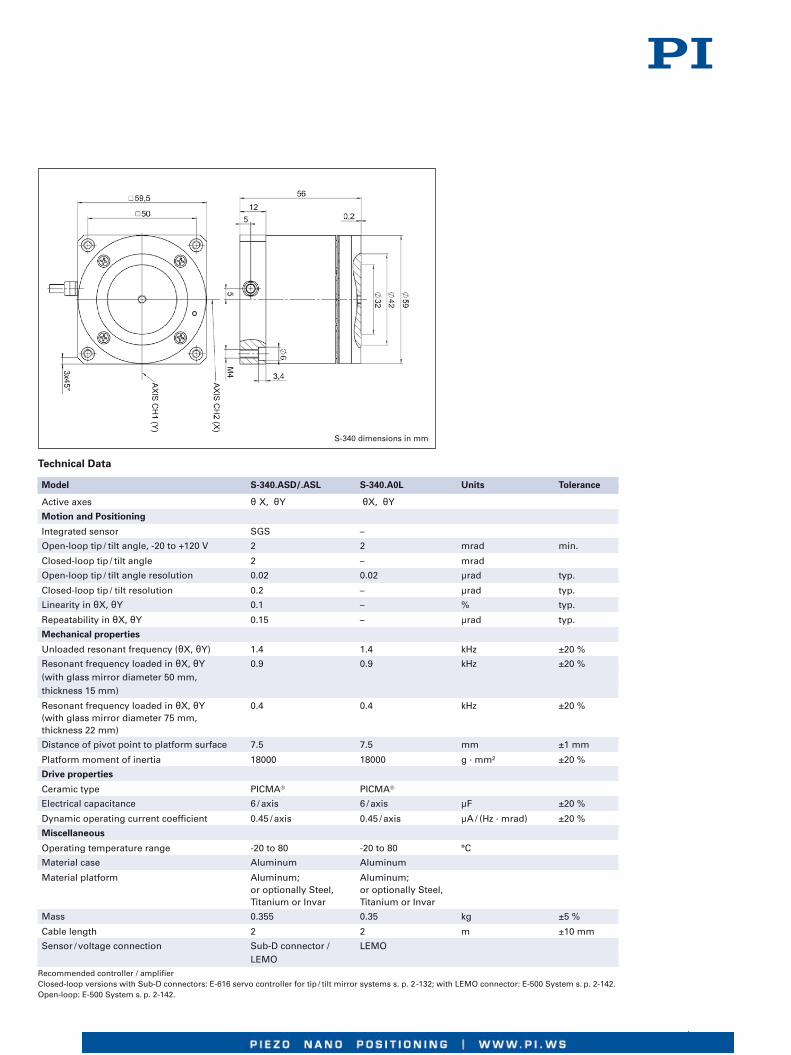
Technical Data
Model S-340.ASD/.ASL S-340.A0L Units Tolerance
Active axes θ X, θY θX, θY
Motion and Positioning
Integrated sensor SGS –
Open-loop tip / tilt angle, -20 to +120 V 2 2 mrad min.
Closed-loop tip / tilt angle 2 – mrad
Open-loop tip / tilt angle resolution 0.02 0.02 µrad typ.
Closed-loop tip / tilt resolution 0.2 – µrad typ.
Linearity in θX, θY 0.1 – % typ.
Repeatability in θX, θY 0.15 – µrad typ.
Mechanical properties
Unloaded resonant frequency (θX, θY) 1.4 1.4 kHz ±20 %
Resonant frequency loaded in θX, θY 0.9 0.9 kHz ±20 %(with glass mirror diameter 50 mm,thickness 15 mm)
Resonant frequency loaded in θX, θY 0.4 0.4 kHz ±20 %(with glass mirror diameter 75 mm,thickness 22 mm)
Distance of pivot point to platform surface 7.5 7.5 mm ±1 mm
Platform moment of inertia 18000 18000 g · mm² ±20 %
Drive properties
Ceramic type PICMA® PICMA®
Electrical capacitance 6 / axis 6 / axis µF ±20 %
Dynamic operating current coefficient 0.45 / axis 0.45 / axis µA / (Hz · mrad) ±20 %
Miscellaneous
Operating temperature range -20 to 80 -20 to 80 °C
Material case Aluminum Aluminum
Material platform Aluminum; Aluminum;or optionally Steel, or optionally Steel,Titanium or Invar Titanium or Invar
Mass 0.355 0.35 kg ±5 %
Cable length 2 2 m ±10 mm
Sensor / voltage connection Sub-D connector / LEMOLEMO
Recommended controller / amplifierClosed-loop versions with Sub-D connectors: E-616 servo controller for tip / tilt mirror systems s. p. 2-132; with LEMO connector: E-500 System s. p. 2-142.Open-loop: E-500 System s. p. 2-142.
S-340 dimensions in mm

©P
hys
ikIn
stru
men
te(P
I)G
mb
H&
Co
.KG
2008
.Su
bje
ctto
chan
ge
wit
ho
ut
no
tice
.All
dat
aar
esu
per
sed
edb
yan
yn
ewre
leas
e.T
he
new
est
rele
ase
for
dat
ash
eets
isav
aila
ble
for
do
wn
load
atw
ww
.pi.w
s.R
210
/03/
10.0
Application Examples
� Image processing /stablilization
� Interferometry
� Laser scanning /beam steering
� Laser tuning
� Optical filters / switches
� Beam stabilization
High-Speed System with Clear Aperture
S-310 – S-316 Piezo Z/Tip/Tilt Scanner
S-310 to S-316 multi-axis tip/tiltplatforms and Z-positioners arefast, compact units based on apiezo tripod design. They offerpiston movement up to 12 µmand tilt movement up to1.2 mrad (2.4 mrad optical beamdeflection) with sub-millisecondresponse and settling. The tri-
pod design features optimumangular stability over a widetemperature range.
The systems are designedfor mirrors and optics up to25 mm in diameter and can bemounted in any orientation; theclear aperture is ideal for trans-mitted-light applications (e. g.for optical filters).
Open-Loop and Closed-Loop
Operation
In open-loop mode, the tip/tiltangle is roughly proportionalto the applied voltage. TheS-310 to S-315 open-loop mod-els are ideal for high-speed,high resolution applicationswhere the absolute angular po-sition is of secondary impor-tance (e. g. for tracking) or
where feedback is provided byan external sensor (e. g. CCD,PSD). The S-316.10 model isequipped with high-resolutionstrain gauge sensors and pro-vides absolute position control,high linearity and high repeata-bility.
Available Versions
� S-310.10, S-314.10
Open-loop Z-platforms; allthree piezo linear actuators areelectrically connected in paral-lel, providing vertical position-ing (piston movement) of thetop ring. Only one drive chan-nel is required.
� S-311.10, S-315.10
Open-loop Z/tip/tilt positioners;all three piezo linear actuatorscan be driven individually (or inparallel) by a three-channel am-plifier. Vertical (piston move-ment) positioning and tip/tiltpositioning are possible.
� S-316.10
Closed-loop Z/tip/tilt positioner.All three piezo linear actuatorsare equipped with strain gaugeposition feedback sensors andcan be driven individually (or inparallel) by a three-channel am-
� 10 mm Clear Aperture
� Piezo Tripod Design
� Optical Beam Deflection to 2,4 mrad
� Piston Movement up to 12 μm (phase shifter)
� Sub-Millisecond Response, Sub-Microradian Resolution
� Closed-Loop Versions for Higher Precision
� For Optics, Mirrors or Other Components
� Frictionless, High-Precision Flexure Guiding System
� Parallel Kinematics for Enhanced Dynamics and Better Multi-
Axis Accuracy
S-316 cable configuration
plifier with a position servo-controller. Vertical positioning(piston movement) and tip/tiltpositioning are possible. Theintegrated position feedbacksensors provide sub-microra-dian resolution and high re-peatability.
S-315 cable configuration
Ordering Information
S-310.10
Piezo Actuator, Clear Aperture,6 µm, LEMO Connector
S-311.10
Piezo Z/Tip/Tilt Platform,Clear Aperture, 600 µrad, 6 µm,LEMO Connector
S-314.10
Piezo Actuator, Clear Aperture,12 µm, LEMO Connector
S-315.10
Piezo Z/Tip/Tilt Platform,Clear Aperture, 1.2 mrad, 12 µm,LEMO Connector
S-316.10
Piezo Z/Tip/Tilt Platform,Clear Aperture, 1.2 mrad, 12 µm,SGS, LEMO Connector
S-316.10D
Piezo Z/Tip/Tilt Platform,Clear Aperture, 1.2 mrad, 12 µm,SGS, Sub-D Connector
S-310.10, S-316.10piezo systems for scanning,
optics alignment and mirror shifter alignment

Resolution of PI piezo tip/tilt plat-forms is not limited by friction orstiction. Noise equivalent motionwith E-503 amplifier(p. 2-146).
*Mechanical tilt, optical beamdeflection is twice as large. Formaximum tilt range, all threepiezo actuators must be biasedat 50 V. Due to the parallel-kine-matics design linear travel andtilt angle are interdependent.The values quoted here refer topure linear / pure angular mo-tion (equations p. 2-84).
Recommended controller / am-plifierSingle-channel (1 per axis):E-610 servo-controller / amplifier(p. 2-110), E-625 servo-controller,bench-top (p. 2-114)
Multi-channel: modular piezocontroller system E-500 (p. 2-142)with amplifier moduleE-503 (three channels) (p. 2-146)or E-505 (1 per axis, high-power)(p. 2-147) and E-509 controller(p. 2-152) (optional), E-517 inter-face module (p. 2-156) (optional)
S-310 – S-316 dimensions (in mm)
High Reliability and Long Life-
time
The compact S-310 - S-316systems are equipped withpreloaded PICMA® high-perfor-mance piezo actuators whichare integrated into a sophisti-cated, FEA-modeled, flexureguiding system. The PICMA®
actuators feature cofired cera-mic encapsulation and providebetter performance and relia-bility than conventional piezoactuators. Actuators, guidanceand sensors are maintenance-free, not subject to wear andoffer extraordinary reliability.
Technical Data
Model S-310.10 S-314.10 S-311.10 S-315.10 S-316.10 Units Tolerance
Active axes Z Z Z, �X, �Y Z, �X, �Y Z, �X, �Y
Motion and positioning
Integrated sensor – – – – SGSOpen-loop travel, 0 to +100 V 6 / – 12 / – 6 / – 12 / – 12 / 12 µm min. (+20 %/-0 %)*Open-loop tilt angle @ 0 to 100 V – – 600 1200 1200 µrad min. (+20 %/-0 %)Closed-loop travel – – – – 12 µm*Closed-loop tilt angle – – – – 1200 µradOpen-loop resolution 0.1 0.2 0.1 0.2 0.2 nm typ.Open-loop tip/tilt angle resolution 0.02 0.05 0.05 µrad typ.Closed-loop resolution – – – – 0.4 nm typ.Closed-loop tip/tilt resolution – – – – 0.1 µrad typ.Linearity – – – – 0.2 % typ.Mechanical properties
Stiffness 20 10 20 10 10 N/µm ±20 %Unloaded resonant frequency (Z) 9.5 5.5 9.5 5.5 5.5 kHz ±20 %Resonant frequency 6.5 4.4 6.5 4.1 4.1 kHz ±20 %(with 15 x 4 mm glass mirror)Resonant frequency 6.1 4.2 6.1 3.4 3.4 kHz ±20 %(with 20 x 4 mm glass mirror)
Distance of pivot point – – 5 5 5 mm ±1 mmto platform surface
Platform moment of inertia – – 150 150 150 g • mm² ±20 %Drive properties
Ceramic type PICMA® PICMA® PICMA® PICMA® PICMA®
P-882 P-882 P-882 P-882 P-882
Electrical capacitance 0.39 0.93 0.39 0.93 0.93 µF ±20 %Dynamic operating current coefficient 8 10 8 10 10 µA / (Hz • mrad) ±20 %Miscellaneous
Operating temperature range -20 to 80 -20 to 80 -20 to 80 -20 to 80 -20 to 80 °CMaterial Stainless Stainless Stainless Stainless Stainless
steel steel steel steel steel
Mass 0.045 0.055 0.045 0.055 0.055 kg ±5%Cable length 2 2 2 2 2 m ±10 mmSensor connection – – – – LEMOVoltage connection LEMO LEMO LEMO LEMO LEMO
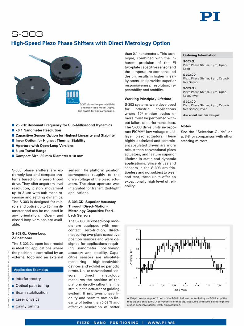
S-303 phase shifters are ex-tremely fast and compact sys-tems based on a piezo tripoddrive. They offer angstrom levelresolution, piston movementup to 3 µm with sub-msec re-sponse and settling dynamics.The S-303 is designed for mir-rors and optics up to 25 mm di-ameter and can be mounted inany orientation. Open- andclosed-loop versions are avail-able.
S-303.0L: Open-Loop
Z-Positioner
The S-303.0L open-loop modelis ideal for applications wherethe position is controlled by anexternal loop and an external
sensor. The platform positioncorresponds roughly to thedrive voltage of the piezo actu-ators. The clear aperture wasintegrated for transmitted-lightapplications.
S-303.CD: Superior Accuracy
Through Direct-Motion-
Metrology Capacitive Feed-
back Sensors
The S-303.CD closed-loop mod-els are equipped with non-contact, zero-friction, direct-measuring two-plate capacitiveposition sensors and were de-signed for applications requir-ing nanometer positioningaccuracy and stability. Capa-citive sensors are absolute-measuring high-bandwidthdevices and exhibit no periodicerrors. Unlike conventional sen-sors, direct metrologymeasures the position of theplatform directly rather than thestrain in the actuator or guidingsystem. It improves phase fi-delity and permits motion lin-earity of better than 0.03 % andeffective resolution of better
than 0.1 nanometers. This tech-nique, combined with the in-herent precision of the PItwo-plate capacitive sensor andthe temperature-compensateddesign, results in higher linear-ity scans, and provides superiorresponsiveness, resolution, re-peatability and stability.
Working Principle / Lifetime
S-303 systems were developedfor industrial applicationswhere 109 motion cycles ormore must be performed with-out failure or performance loss.The S-303 drive units incorpo-rate PICMA® low-voltage multi-layer piezo actuators. Thesehighly optimized and ceramic-encapsulated drives are morerobust than conventional piezoactuators, and feature superiorlifetime in static and dynamicapplications. Since drives andsensors in the S-303 are fric-tionless and not subject to wearand tear, these units offer anexceptionally high level of reli-ability.
Application Examples
� Interferometry
� Optical path tuning
� Beam stabilization
� Laser physics
� Cavity tuning
Ordering Information
S-303.0L
Piezo Phase Shifter, 3 µm, Open-Loop
S-303.CD
Piezo Phase Shifter, 2 µm, Capaci-tive Sensor
S-303.0Li
Piezo Phase Shifter, 3 µm, Open-Loop, Invar
S-303.CDi
Piezo Phase Shifter, 2 µm, Capaci-tive Sensor, Invar
Ask about custom designs!
High-Speed Piezo Phase Shifters with Direct Metrology Option
S-303
A 250 picometer step (0.25 nm) of the S-303 platform, controlled by an E-503 amplifiermodule and an E-509.C1A servocontroller module. Measured with special ultra-high-res-olution capacitive gauge, ±0.02 nm resolution.
� 25 kHz Resonant Frequency for Sub-Millisecond Dynamics
� <0.1 Nanometer Resolution
� Capacitive Sensor Option for Highest Linearity and Stability
� Invar Option for Highest Thermal Stability
� Aperture with Open-Loop Versions
� 3 μm Travel Range
� Compact Size: 30 mm Diameter x 10 mm
S-303 closed-loop model (left)and open-loop model (right).
Dip switch for size comparison.
©P
I199
8-20
05.S
ub
ject
toch
ang
ew
/on
oti
ce.R
110
/04/
28.0
Notes
See the “Selection Guide” onp. 3-8 for comparison with othersteering mirrors.

Technical Data
Models S-303.CDx S-303.0Lx Units Notes see
page 3-26
Active axes Z Z
Min. Open-loop travel @ -20 to +120 V 3 3 µm ±20% A2
Closed-loop travel 2 - µm A5
Integrated feedback sensor capacitive - B
* Closed-loop / open-loop resolution 0.03 / 0.03 - / 0.03 nm C1
** Closed-loop linearity (typ.) 1.0 - %
Full-range repeatability (typ.) 0.7 - nm C
Stiffness N/µm ±20% D1
Max. (±) normal load 0.5 0.5 N D4
Electrical capacitance 0.9 0.9 µF ±20% F1
*** Dynamic operating 50 50 µA/(Hz x µm) F2current coefficient (DOCC)
Unloaded resonant frequency 25 25 kHz ±20% G2
Operating temperature range -20 to 80 -20 to 80 °C H2
Voltage connection D VL J1
Sensor connection D - J2
Mass 100 30 g ±5%
Body material Al, Invar optional Al, Invar optional L
Recommended Amplifier / Controller F, M G, C(codes explained page 3-9)
Dimensions of the S-303.CDx in mm
* For calibration informa-tion see p. 3-7.Resolution of PZT Nano-positioners is not limitedby friction orstiction. Noise equivalentmotion with E-503, E-710.
** With digital controller,analog controllers willprovide a linearity of typ.1 nm.
*** Dynamic Operating Cur-rent Coefficient in µA perHz and µm.Example: Sinusoidal scanof 1 µm at 10 Hz requiresapproximately 0.5 mAdrive current.
Dimensions of the S-303.0Lx in mm

PI Steering Mirrors and Alignment Systems in Astronomy
Custom Systems for Telescopes
Resolution in large earthboundtelescopes is limited by atmos-pheric turbulence and vibra-tions. During the last 15 yearsPI has designed several large-aperture tip/tilt systems forimage stabilization. Piezo-electrically driven active sec-ondary mirrors can improvethe effective resolution up to1000 % by correcting for theseimage shifts in real time, espe-cially during long integrationswith weak light sources.
Momentum Compensation
Due to the inertia of the largemirrors and the high accelera-tions required to correct forimage fluctuations, significantforces can be induced in thetelescope structure, causingunwanted vibrations. PI hasdeveloped momentum com-pensation systems integratedinto the tip/tilt platforms whichcancel undesirable vibrationsand thus offer significantly bet-ter stabilization than uncom-pensated systems.
High-Resolution Linear Actuators
273 PI actuators are used fortip/tilt/piston movement of segment-ed mirror panels in the SALTTelescope.Features: 16 nm design resolution;0.15 µm minimum incrementalmotion; non-rotating tip, compactdesign.
Example of a combined high-speed piezo tip/tilt plaftform with a long range, low-speed6-axis hexapod alignment system
25cm secondary mirror
Piezo driven steering
platform, µm/mrad range;
nm/nrad precision
Momentum compensation
Hexapod actuators
range: mm/degrees
resolution: µm/µrad
Base plate
Keck I and Keck II observatories and NASA Infrared Telescope Facility (IRTF)(silver dome), Mauna Kea, Hawaii; Photo: K. Spanner.
The Horsehead Nebula;Photo: Brian Lula.
Active tip/tilt mirror system for the KeckOutrigger telescope in Hawaii. The units arecontrolled by a high-performance digitalcontroller with a fiber optic interface (notshown).Mirror diameter: 250 mmTip/tilt range: ±150 µradResolution: nanoradian rangePosition measurement: capacitive

USA (East) & CANADA USA (West) & MEXICO
PI (Physik Instrumente) L.P. PI (Physik Instrumente) L.P.16 Albert St. 5420 Trabuco Rd., Suite 100 Auburn, MA 01501 Irvine, CA 92620Tel: +1 (508) 832 3456 Tel: +1 (949) 679 9191Fax: +1 (508) 832 0506 Fax: +1 (949) 679 [email protected] [email protected] www.pi-usa.us
JAPAN
PI Japan Co., Ltd. PI Japan Co., Ltd.Akebono-cho 2-38-5 Hanahara Dai-ni Building, #703Tachikawa-shi 4-11-27 Nishinakajima,J-Tokyo 190 Yodogawa-ku, Osaka-shiTel: +81 (42) 526 7300 J-Osaka 532Fax: +81 (42) 526 7301 Tel: +81 (6) 6304 [email protected] Fax: +81 (6) 6304 5606www.pi-japan.jp [email protected]
www.pi-japan.jp
CHINA UK & IRELAND
Physik Instrumente PI (Physik Instrumente) Ltd.(PI Shanghai) Co., Ltd. Trent HouseBuilding No. 7-301 University Way,Longdong Avenue 3000 Cranfield Technology Park,201203 Shanghai, China Cranfield,Tel: +86 (21) 687 900 08 Bedford MK43 0ANFax: +86 (21) 687 900 98 Tel: +44 (1234) 756 [email protected] Fax: +44 (1234) 756 369www.pi-china.cn [email protected]
www.physikinstrumente.co.uk
ITALY
Physik Instrumente (PI) S.r.l.Via G. Marconi, 28I-20091 Bresso (MI)Tel: +39 (02) 665 011 01Fax: +39 (02) 873 859 [email protected]
FRANCE
PI France S.A.S244 bis, avenue Max Dormoy92120 MontrougeTel: +33 (1) 55 22 60 00 Fax: +33 (1) 41 48 56 62
GERMANY
Physik Instrumente (PI)GmbH & Co. KGAuf der Römerstr. 1D-76228 Karlsruhe/PalmbachTel: +49 (721) 4846-0 Fax: +49 (721) [email protected] · www.pi.ws
Program Overview
� Piezo Ceramic Actuators & Motors
� Piezo Nanopositioning Systems and Scanners
� Active Optics / Tip-Tilt Platforms
� Capacitive Nanometrology Sensors
� Piezo Electronics: Amplifiers and Controllers
� Hexapod 6-Axis Positioners / Robots
� Micropositioning Stages & Actuators
� Photonics Alignment Systems, Solutions forTelecommunications
� Motor Controllers
� Ultrasonic Linear Motors
Request or download the completePI Nanopositioning & Piezo ActuatorCatalog