piano hi-fi dac 2.1 technical manual - … · piano hi-fi dac 2.1 (with subwoofer output) piano...
TRANSCRIPT
PIANO Hi-Fi DAC 2.1
TECHNICAL MANUAL
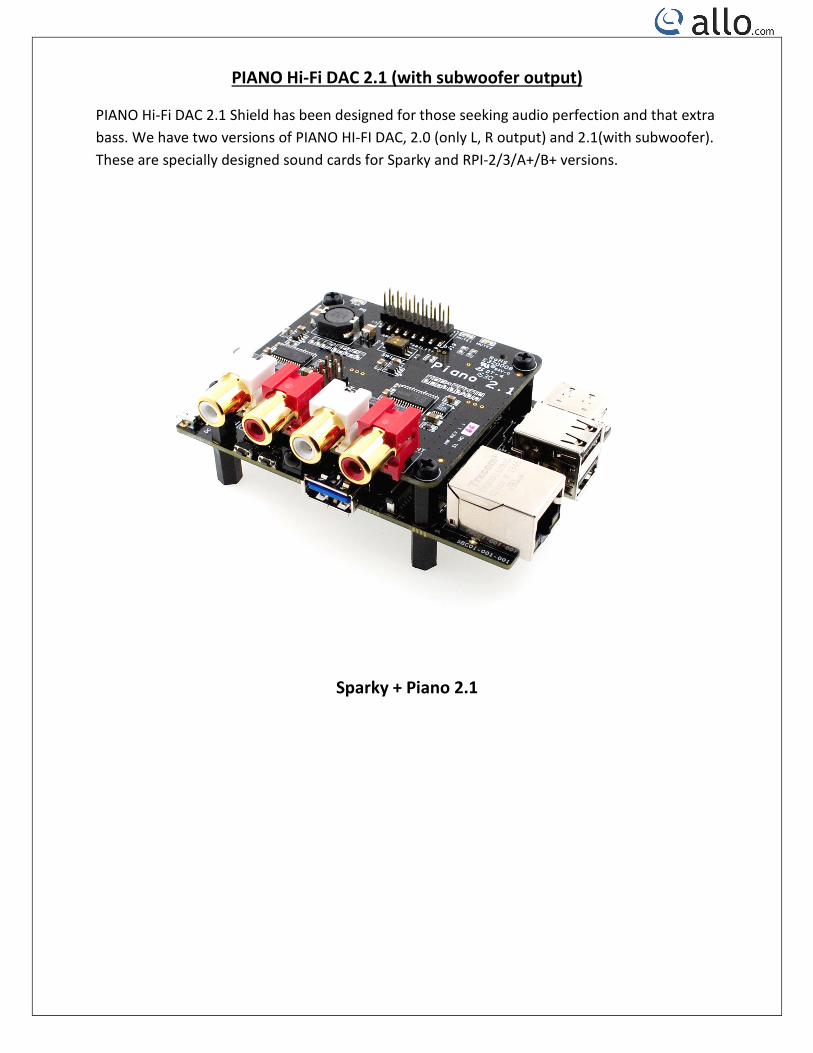
PIANO Hi-Fi DAC 2.1 (with subwoofer output)
PIANO Hi-Fi DAC 2.1 Shield has been designed for those seeking audio perfection and that extra bass. We have two versions of PIANO HI-FI DAC, 2.0 (only L, R output) and 2.1(with subwoofer). These are specially designed sound cards for Sparky and RPI-2/3/A+/B+ versions.
Sparky + Piano 2.1
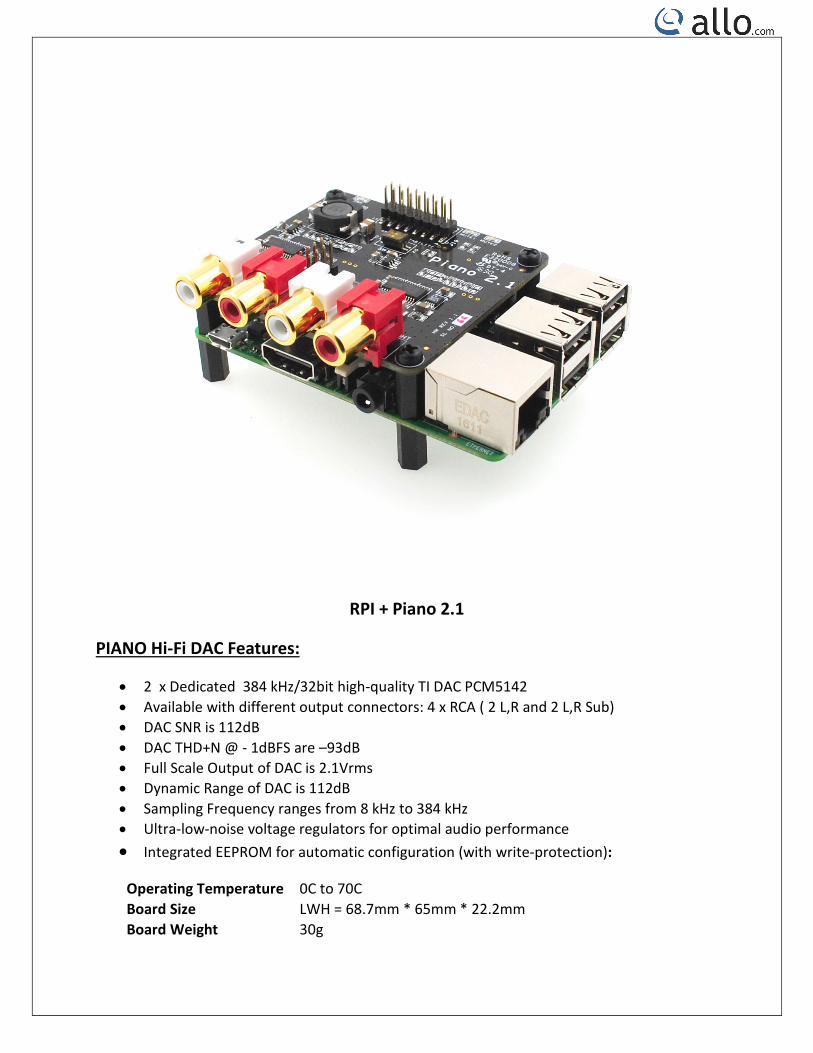
RPI + Piano 2.1
PIANO Hi-Fi DAC Features:
• 2 x Dedicated 384 kHz/32bit high-quality TI DAC PCM5142 • Available with different output connectors: 4 x RCA ( 2 L,R and 2 L,R Sub) • DAC SNR is 112dB • DAC THD+N @ - 1dBFS are –93dB • Full Scale Output of DAC is 2.1Vrms • Dynamic Range of DAC is 112dB • Sampling Frequency ranges from 8 kHz to 384 kHz • Ultra-low-noise voltage regulators for optimal audio performance • Integrated EEPROM for automatic configuration (with write-protection):
Operating Temperature 0C to 70C Board Size LWH = 68.7mm * 65mm * 22.2mm Board Weight 30g
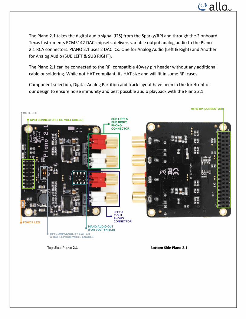
The Piano 2.1 takes the digital audio signal (I2S) from the Sparky/RPI and through the 2 onboard Texas Instruments PCM5142 DAC chipsets, delivers variable output analog audio to the Piano 2.1 RCA connectors. PIANO 2.1 uses 2 DAC ICs: One for Analog Audio (Left & Right) and Another for Analog Audio (SUB LEFT & SUB RIGHT).
The Piano 2.1 can be connected to the RPI compatible 40way pin header without any additional cable or soldering. While not HAT compliant, its HAT size and will fit in some RPI cases.
Component selection, Digital-Analog Partition and track layout have been in the forefront of our design to ensure noise immunity and best possible audio playback with the Piano 2.1.
Top Side Piano 2.1 Bottom Side Piano 2.1
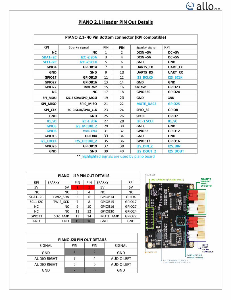
PIANO 2.1 Header PIN Out Details
PIANO 2.1- 40 Pin Bottom connector (RPI compatible)
RPI Sparky signal PIN PIN Sparky signal RPI NC NC 1 2 DCIN +5V DC +5V
SDA1-I2C I2C -2 SDA 3 4 DCIN +5V DC +5V SCL1-I2C I2C -2 SCLK 5 6 GND GND
GPIO4 GPIOB14 7 8 UART5_TX UART_TX GND GND 9 10 UART5_RX UART_RX
GPIO17 GPIOB15 11 12 I2S_BCLK0 I2S_BCLK GPIO27 GPIOB16 13 14 GND GND GPIO22 MUTE_AMP 15 16 SDZ_AMP GPIO23
NC NC 17 18 GPIOB30 GPIO24 SPI_MOSI I2C-3 SDA/SPI0_MOSI 19 20 GND GND
SPI_MISO SPI0_MISO 21 22 MUTE_DAC2 GPIO25
SPI_CLK I2C -3 SCLK/SPIO_CLK 23 24 SPIO_SS GPIO8
GND GND 25 26 SPDIF GPIO7 ID_SD I2C-1 SDA 27 28 I2C -1 SCLK ID_SC GPIO5 I2S_MCLK0_2 29 30 GND GND GPIO6 MUTE_DAC1 31 32 GPIOB3 GPIO12
GPIO13 GPIOB4 33 34 GND GND I2S_LRCLK I2S_LRCLK0_2 35 36 GPIOB13 GPIO16
GPIO26 GPIOB19 37 38 I2S_DIN_2 I2S_DIN GND GND 39 40 I2S_DOUT_2 I2S_DOUT
** highlighted signals are used by piano board
PIANO J19 PIN OUT DETAILS
RPI SPARKY PIN PIN SPARKY RPI 5V 5V 1 2 5V 5V NC NC 3 4 NC NC
SDA1-I2C TWI2_SDA 5 6 GPIOB14 GPIO4 SCL1-I2C TWI2_SCK 7 8 GPIOB15 GPIO17
NC NC 9 10 GPIOB16 GPIO27 NC NC 11 12 GPIOB30 GPIO24
GPIO23 SDZ_AMP 13 14 MUTE_AMP GPIO22 GND GND 15 16 GND GND
PIANO J20 PIN OUT DETAILS SIGNAL PIN PIN SIGNAL
GND 1 2 GND AUDIO RIGHT 3 4 AUDIO LEFT AUDIO RIGHT 5 6 AUDIO LEFT
GND 7 8 GND
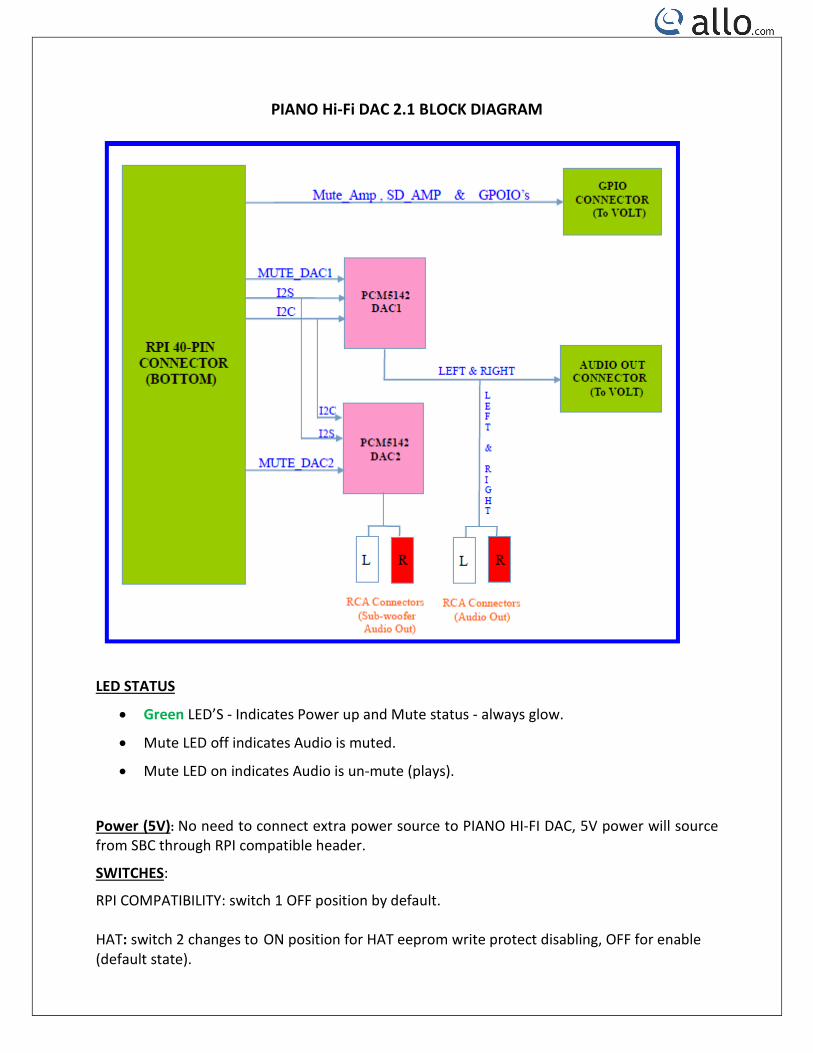
PIANO Hi-Fi DAC 2.1 BLOCK DIAGRAM
LED STATUS
• Green LED’S - Indicates Power up and Mute status - always glow.
• Mute LED off indicates Audio is muted.
• Mute LED on indicates Audio is un-mute (plays).
Power (5V): No need to connect extra power source to PIANO HI-FI DAC, 5V power will source from SBC through RPI compatible header.
SWITCHES:
RPI COMPATIBILITY: switch 1 OFF position by default. HAT: switch 2 changes to ON position for HAT eeprom write protect disabling, OFF for enable (default state).