physiological effects of electricity on human body by mohd yusof baharuddin
TRANSCRIPT

Physiological Effects of Electricity on Human Body
by
Mohd Yusof Baharuddin

Objectives
Describe and explain on the accumulation of data from variety of sources has established the effect of alternating electrical currents (frequency 50-60 Hz).
Discuss the leakage current

Are you aware ???

Introduction
Electrical current which passing through human body will caused:
Injuries to tissue - burns
Muscle stimulation – uncontrollable muscle contraction or unconsciousness
Fibrillation of the heart


Effect of 60 Hz electric Shock (Current) through body
Current Intensity Effect
1 mA Threshold of perception
5 mA Accepted as maximum harmless current intensity
10 - 20 mA Pain. Possible fainting, exhaustion, mechanical injury, heart & respiratory functions continue
100 - 300 mA Ventricular fibrillation will start but respiratory center remains intact
Sustained myocardial contraction followed by normal heart rhythm. Temporary respiratory paralysis. Burns if current density is high
6 A
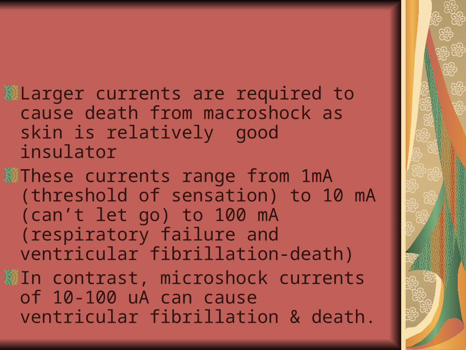
Larger currents are required to cause death from macroshock as skin is relatively good insulatorThese currents range from 1mA (threshold of sensation) to 10 mA (can’t let go) to 100 mA (respiratory failure and ventricular fibrillation-death)In contrast, microshock currents of 10-100 uA can cause ventricular fibrillation & death.

Frequency of the current
For example, an arm to arm shock @ 50-60 Hz is particularly potent compared to higher or lower frequency.However if the frequency is increased above 1 kHz, these current levels no longer produce such sensations or life threatening phenomena.High frequency in MHz will caused serious burn than shock. Relates to electrosurgical unit.


Class I Equipment
Class I equipment has a protective earth. The basic means of protection is the insulation between live parts and exposed conductive parts such as the metal enclosure. In the event of a fault that would otherwise cause an exposed conductive part to become live, the supplementary protection (i.e. the protective earth) comes into effect. A large fault current flows from the mains part to earth via the protective earth conductor, which causes a protective device (usually a fuse) in the mains circuit to disconnect the equipment from the supply.

Class I Equipment
It is important to realize that not all equipment having an earth connection is necessarily Class I.
The earth conductor may be for functional purposes only such as screening. In this case the size of the conductor may not be large enough to safely carry a fault current that would flow in the event of a mains short to earth for the length of time required for the fuse to disconnect the supply.

Class I EquipmentClass I medical electrical equipment should have fuses at the equipment end of the mains supply lead in both the live and neutral conductors, so that the supplementary protection is operative when the equipment is connected to an incorrectly wired socket outlet. Further confusion can arise due to the use of plastic laminates for finishing equipment. A case that appears to be plastic does not necessarily indicate that the equipment is not class I. There is no agreed symbol in use to indicate that equipment is class I and it is not mandatory to state on the equipment itself that it is class I. Where any doubt exists, reference should be made to equipment manuals.


Class II Equipment
The method of protection against electric shock in the case of class II equipment is either double insulation or reinforced insulation.
In double insulated equipment the basic protection is afforded by the first layer of insulation. If the basic protection fails then supplementary protection is provided by a second layer of insulation preventing contact with live parts.

Class II Equipment
In practice, the basic insulation may be afforded by physical separation of live conductors from the equipment enclosure, so that the basic insulation material is air. The enclosure material then forms the supplementary insulation. Reinforced insulation is defined in standards as being a single layer of insulation offering the same degree of protection against electric shock as double insulation. Class II medical electrical equipment should be fused at the equipment end of the supply lead in either mains conductor or in both conductors if the equipment has a functional earth.


Class III Equipment
Class III equipment is defined in some equipment standards as that in which protection against electric shock relies on the fact that no voltages higher than safety extra low voltage (SELV) are present. SELV is defined in turn in the relevant standard as a voltage not exceeding 25V ac or 60V dc. In practice such equipment is either battery operated or supplied by a SELV transformer.

Class III Equipment
If battery operated equipment is capable of being operated when connected to the mains (for example, for battery charging) then it must be safety tested as either class I or class II equipment.
Similarly, equipment powered from a SELV transformer should be tested in conjunction with the transformer as class I or class II equipment as appropriate.

Class III Equipment
It is interesting to note that the current IEC standards relating to safety of medical electrical equipment do not recognize Class III equipment since limitation of voltage is not deemed sufficient to ensure safety of the patient. All medical electrical equipment that is capable of mains connection must be classified as class I or class II. Medical electrical equipment having no mains connection is simply referred to as "internally powered".


Causes of leakage current
If any conductor is raised to a potential above that of earth, some current is bound to flow from that conductor to earth. This is true even of conductors that are well insulated from earth, since there is no such thing as perfect insulation or infinite impedance. The amount of current that flows depends on:
the voltage on the conductor. the capacitive reactance between the conductor and earth. the resistance between the conductor and earth.

Earth Leakage Current
Earth leakage current is the current that normally flows in the earth conductor of a protectively earthed piece of equipment.In medical electrical equipment, very often, the mains is connected to a transformer having an earthed screen. Most of the earth leakage current finds its way to earth via the impedance of the insulation between the transformer primary and the inter-winding screen, since this is the point at which the insulation impedance is at its lowest

Earth Leakage Current
Under normal conditions, a person who is in contact with the earthed metal enclosure of the equipment and with another earthed object would suffer no adverse effects even if a fairly large earth leakage current were to flow. This is because the impedance to earth from the enclosure is much lower through the protective earth conductor than it is through the person. However, if the protective earth conductor becomes open circuited, then the situation changes. Now, if the impedance between the transformer primary and the enclosure is of the same order of magnitude as the impedance between the enclosure and earth through the person, a shock hazard exists.

Earth Leakage Current
It is a fundamental safety requirement that in the event of a single fault occurring, such as the earth becoming open circuit, no hazard should exist. It is clear that in order for this to be the case in the above example, the impedance between the mains part (the transformer primary and so on) and the enclosure needs to be high. This would be evidenced when the equipment is in the normal condition by a low earth leakage current. In other words, if the earth leakage current is low then the risk of electric shock in the event of a fault is minimized.

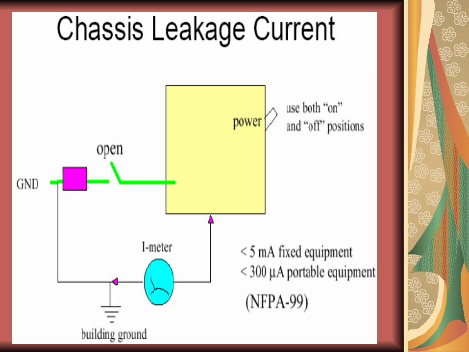
Enclosure Leakage Current
The terms "enclosure leakage current" and "touch current" should be taken to be synonymous. Enclosure leakage current is defined as the current that flows from an exposed conductive part of the enclosure to earth through a conductor other than the protective earth conductor.

Enclosure Leakage Current
If a protective earth conductor is connected to the enclosure, there is little point in attempting to measure the enclosure leakage current from another protectively earthed point on the enclosure, since any measuring device used is effectively shorted out by the low resistance of the protective earth. Equally, there is little point in measuring the enclosure leakage current from a protectively earthed point on the enclosure with the protective earth open circuit, since this would give the same reading as measurement of earth leakage current as described above.

Enclosure Leakage Current
For these reasons, it is usual when testing medical electrical equipment to measure enclosure leakage current from points on the enclosure that are not intended to be protectively earthed. On many pieces of equipment, no such points exist. This is not a problem. The test is included in test regimes to cover the eventuality where such points do exist and to ensure that no hazardous leakage currents will flow from them.

Patient Leakage Current
Patient leakage current is the leakage current that flows through a patient connected to an applied part or parts. It can either flow from the applied parts via the patient to earth or from an external source of high potential via the patient and the applied parts to earth.

Patient Auxiliary Current
The patient auxiliary current is defined as the current that normally flows between parts of the applied part through the patient, which is not intended to produce a physiological effect


Summary
Currents Intensity 1mA (threshold of sensation) to 10 mA (can’t let go) to 100 mA (respiratory failure and ventricular fibrillation-death)
Type of Class – Class I, II & III
Type of equipment – B, BF & CF
Leakage CurrentEarth leakage current
Enclosure leakage current
Patient leakage current
Patient auxiliary current
