photonic dual rf beam reception of an x band phased array antenna using a photonic crystal...
TRANSCRIPT

Photonic dual RF beam reception of an X band phasedarray antenna using a photonic crystal fiber-based
true-time-delay beamformer
Harish Subbaraman,1 Maggie Yihong Chen,2 and Ray T. Chen1,*1Microelectronics Research Center, Department of Electrical and Computer Engineering, University of Texas at Austin, Austin,
Texas 78758, USA2Omega Optics, Inc., 10435 Burnet Road, Suite 108, Austin, Texas 78758, USA
*Corresponding author: [email protected]
Received 8 July 2008; revised 21 October 2008; accepted 29 October 2008;posted 30 October 2008 (Doc. ID 97957); published 27 November 2008
We report dual RF beam reception of an X band phased array antenna using a photonic crystal fiber(PCF)-based delay network. Each incoming RF signal can be independently received, and the angleof arrival can be determined based on the delay time-dependent wavelength. Two RF signals with fre-quencies 8.4 and 12GHz impinge upon anX-band antenna array from −7:4° and −21:2°. These signals aredetected, and the angle of arrival is determined with a very good degree of accuracy using PCF-basedtrue-time delay. The total number of RF beams that can be simultaneously detected is limited by thehardware availability and the bandwidth of the wavelength differentiation capability of the system.© 2008 Optical Society of AmericaOCIS codes: 060.4005, 060.5295, 280.5110.
1. Introduction
Phased array antenna (PAA) is a key component inmany of the modern military and commercial radarand communication systems. One of the advantagesthat this technology offers is a physical movement-free RF beam steering. However, electrical phaseshifters are inherently narrowband. This calls fortechnologies that have a larger bandwidth and highimmunity to electromagnetic interference. Opticaltrue-time delay (TTD) techniques are capable of pro-viding these features along with the ability to pro-vide squint-free operation. Many optical schemeshave been proposed to form a photonic feed for TTD.These include acousto-optic integrated circuit techni-que [1], Fourier optical technique [2], bulky opticstechniques [3], dispersive fiber technique [4–8], fibergrating technique [9,10], and substrate-guided wavetechnique [11]. The dispersive fiber technique can
provide a very compact and lightweight system. Con-ventional single-mode fiber (SMF) has a low value ofdispersion, and so it is not a very good choice for thisapplication, as long length of SMF is required to gen-erate large delay values. However, highly dispersivefibers can reduce the overall length of the TTD linesas the required time delay can be generated in a veryshort length of such fibers.
Photonic crystal fibers (PCFs), with a periodic lat-tice of air holes running down the length of the fiber,can be designed to achieve very high dispersionvalues. A W index profile PCF, like the ones usedin conventional dispersion compensation fibers [12],can be used to achieve high dispersion. PCFs with adual-concentric core design have been designed to ex-hibit high dispersion coefficient values [13]. Our fab-ricated fiber design is also based on a dual-concentriccore structure, and the dispersion value of the fiber is∼ − 600ps=nm=km, measured at a wavelength of1550nm, which is 33 times larger compared tothat of a conventional SMF (∼18ps=nm=km at1550nm). Thus a shorter length of PCF compared
0003-6935/08/346448-05$15.00/0© 2008 Optical Society of America
6448 APPLIED OPTICS / Vol. 47, No. 34 / 1 December 2008

to conventional SMF is required to generate thesame amount of delay. This reduces the size andweight of the overall system.In our previously reported research, PCF-based
delay lines for a single RF beam steering was pre-sented [14,15]. Recently we also demonstrated simul-taneous multiple-beam transmission capability ofour PAA system utilizing highly dispersive fibers[16]. In this paper we report with experimental con-firmation the working principle of a photonic crystal-based TTD module with multiple-beam receivingcapability for application in a PAA. Previous archi-tectures used high-dispersion fibers with a disper-sion coefficient of −88ps=nm=km fibers [17,18].Using our highly dispersive PCFs, the length ofthe TTD lines can be reduced by a factor of 7. In Sec-tion 2 we describe the setup and working principle ofa general system for receiving multiple beams. InSection 3 we present our demonstration and experi-mental results for two beam operation at Xband (8–12GHz).
2. Optical Beam Former for Receiving Multiple Beams
Using the PCF-based TTD module, multiple-beamreceiving can be realized by using the scheme asshown in Fig. 1. A general system is shown whereina multiple number (M) of RF signals are received si-multaneously using an antenna array with N ele-ments through a single set of TTD lines.A laser array is used to generate M different opti-
cal carrier waves with wavelengths λ1 to λM. Theseoptical carrier waves are combined together througha wavelength division multiplexer (WDM). The re-ceived RF signals from each antenna element modu-late these optical carrier waves using electro-opticmodulators (EOMs). The outputs of the N EOMsare connected to N TTD lines.Each TTD line consists of different lengths of PCF
(red section) and SMF (blue section), with the overalllength of each TTD line being approximately equaland the lengths chosen in such a way that at a cen-tral wavelength of λ0, the nominal delay througheach TTD line is the same, and the outputs fromthe TTD lines for an RF signal incident normal onthe antenna array are all in phase. At wavelengthsgreater than or less than λ0, different time delaysare induced in each TTD line, with a constant
time-delay difference between adjacent channels atevery wavelength. The time delay between adjacentlines induced by a beam received from an angle θ isgiven by [2]
τ ¼ d: sin θc
; ð1Þ
where τ is the time-delay difference between adja-cent lines, d is the antenna element spacing, and cis the speed of light in free space.
Suppose there are N TTD lines of length L havingPCF segments of lengths L1;L2;L3… and LN , respec-tively, as shown in Fig. 1. In practice, the first delayline consists of a SMF section of length L (L1 ¼ 0),and the Nth delay line consists of a PCF section oflength L (no SMF section). The time delay generatedin the ith delay line is given by
Tdelay;i ¼ Li
Z λ
λ0DPCFðλÞdλþ ðL − LiÞ
Z λ
λ0DSMFðλÞdλ;
i ¼ 1; 2; 3;…N:
ð2Þ
The first term is contributed by the PCF section, andthe second term is contributed by the conventionalSMF. If we consider the difference of delay time, τ,between two adjacent fibers having PCF segmentsof lengths Li and Liþ1, we have
τ ¼ ðLi − Liþ1Þ:Z λ
λ0½DPCFðλÞ −DSMFðλÞ�:dλ;
i ¼ 1; 2; 3…N − 1;
ð3Þ
where τ is the time-delay difference between adja-cent channels generated by λ with respect to λ0.
Since the dispersion value of the PCF is much lar-ger compared to that of the SMF for a fixed wave-length λ, the difference of time delays betweendifferent channels are only determined by thelengths of the PCFs. Therefore, by making thelengths of the PCF an arithmetic sequence, we canachieve equal time-delay differences between adja-cent TTD lines at any given wavelength, thus form-ing a wavelength-tuned TTD line. Since multiplewavelengths are used for multiple incoming signals,the output signals from the TTD lines are fed to awavelength division demultiplexer, where differentoptical wavelengths are separated. At any photode-tector, say PM, the signals corresponding to wave-length λM coming from all delay lines add up. Inorder for all the signals to add up constructivelyfor the corresponding direction, the delay linesshould alter the phase of signals in such a way thatall signals arrive in phase at the photodetector. Sinceevery wavelength generates one set of time delay va-lues in the delay lines for a given angle of arrival, θ,only one wavelength would be able to compensate
Fig. 1. (Color online) Structure of the receiving mode with multi-ple incoming beams. DEMUX, demultiplexer.
1 December 2008 / Vol. 47, No. 34 / APPLIED OPTICS 6449
phase differences between adjacent elements and de-liver maximum power at the photodetector output.The dispersion coefficient of the PCFat each wave-
length is measured by measuring the time delaythrough the PCF at λ� 0:1nm and dividing thetime-delay difference by the length of PCF under testand wavelength span, Δλ ¼ 0:2nm. Figure 2 showsthe measured second-order dispersion coefficient asa function of wavelength. The structural parametersof the PCF are chosen in order to have a phase-matched wavelength near 1550nm. Around thiswavelength, the PCF structure can achieve a peakdispersion coefficient of −600ps=nm=km. By usinga 3:5m PCF length difference between adjacentTTD lines and selecting 1545nm as the central wa-velength, continuous time-delay values from −28:3 toþ31:3ps can be generated by tuning the wavelengthcontinuously from 1530 to 1560nm. Using the X-band array antenna with interelement spacing ¼1:3 cm, also shown as an inset in Fig. 2, continuousbeam steering from −41° to þ46° can be achieved.Therefore, an incoming beam in the angular rangeof −41° to þ46° can be detected, and the angle of ar-rival can be determined accurately. The relationshipbetween the operating wavelength and calculatedsteering angle of the RF beam covering the X band(8–12GHz) is also shown in the figure. This calcu-lated result is later experimentally verified by de-tecting two beams impinging upon the X-bandantenna array from two different angles. By havinga lookup table in the signal processing unit showingthe wavelength-angle relationship, the angle of arri-val can be determined for any RF signal of interestdue to the squint-free nature of the TTD lines [15].Jiang et al. have shown the effects of thermal fluctua-tion on highly dispersive PCFs to be approximately0.28% per °C from 21 °C to 80 °C [19]. The TTD net-work is placed in a temperature-controlled environ-ment, and this leads to an insignificant shift in thebeam steering angle. For a worst case temperature
fluctuation of �5 °C, the worst case error in the beampointing direction is 1.5%.
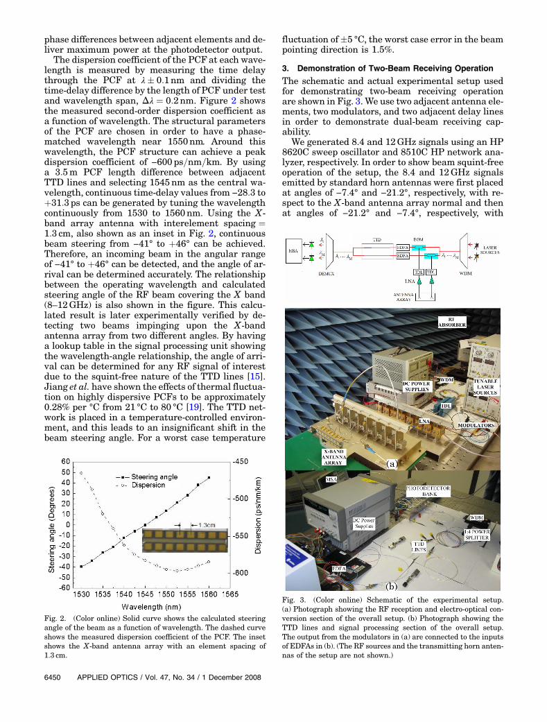
3. Demonstration of Two-Beam Receiving Operation
The schematic and actual experimental setup usedfor demonstrating two-beam receiving operationare shown in Fig. 3. We use two adjacent antenna ele-ments, two modulators, and two adjacent delay linesin order to demonstrate dual-beam receiving cap-ability.
We generated 8.4 and 12GHz signals using an HP8620C sweep oscillator and 8510C HP network ana-lyzer, respectively. In order to show beam squint-freeoperation of the setup, the 8.4 and 12GHz signalsemitted by standard horn antennas were first placedat angles of −7:4° and −21:2°, respectively, with re-spect to the X-band antenna array normal and thenat angles of −21:2° and −7:4°, respectively, with
Fig. 2. (Color online) Solid curve shows the calculated steeringangle of the beam as a function of wavelength. The dashed curveshows the measured dispersion coefficient of the PCF. The insetshows the X-band antenna array with an element spacing of1:3 cm.
Fig. 3. (Color online) Schematic of the experimental setup.(a) Photograph showing the RF reception and electro-optical con-version section of the overall setup. (b) Photograph showing theTTD lines and signal processing section of the overall setup.The output from the modulators in (a) are connected to the inputsof EDFAs in (b). (The RF sources and the transmitting horn anten-nas of the setup are not shown.)
6450 APPLIED OPTICS / Vol. 47, No. 34 / 1 December 2008

respect to the X-band antenna array normal and at adistance of 2m from the antenna array so that theemitting horn and the array antenna are in eachother’s far field. The antenna array consists of ele-ments with a spacing of 1:3 cm. These external RFsignals impinge on the antenna array, and the sig-nals received are amplified using two low-noise am-plifiers (LNAs) that have a gain of 35 dB. The tunabledelay lines (TDLs) are used to fine-tune the delaythrough the lines for initial calibration of the setup.The amplified signals modulate the output signal ofWDM, composed of combined optical wavelengthscoming from two laser sources using two high-speedLiNbO3 modulators. The tunable lasers have a max-imum output power of 8dBm. The optical signals arecombined using a WDM. A maximum of 7dB loss isencountered after passing through the modulator.Themodulated optical signals are amplified using er-bium-doped fiber amplifiers (EDFAs), which have amaximum output of 13dBm and feed to two adjacentdelay lines.The two delay lines consist of 0m of PCF with
10:5m of SMF and 3:5m of PCF with 7m of SMF, re-spectively. The difference in the lengths of PCF sec-tions between adjacent elements is 3:5m. The overalllength of each delay line is only 10:5m. The maxi-mum insertion loss due to the delay lines is 11dB.The lengths of the SMF sections are trimmed suchthat at 1545nm, the delays in each of the delay linesare equal. That is, for an RF signal incident normallyon the antenna array, modulating a wavelength of1545nm, the signal detected at the photodetectorwill be a maximum. Therefore a different angle of ar-rival of RF signal will require a different wavelengthto equalize the phase difference between adjacentelements in the TTD lines and generate a maximum
at the photodetector output. In order to receive abeam from the positive θ direction, the experimentmust be set up such that in the transmitting mode,the beam is steered in the negative θ direction.
The wavelengths are demultiplexed at the outputof the delay lines and fed to a photodetector bank. Amicrowave spectrum analyzer (MSA) is used to moni-tor the detected RF output power from the photode-tectors. Although one tunable laser source issufficient to detect all of the impinging RF signals,one tunable laser source per RF signal will enableus to lock one signal with one tunable laser sourcewhile scanning for other signals using other lasersources. Therefore we use two tunable lasers for lock-ing and detecting the 8.4 and 12GHz signals inde-pendently. The wavelengths on the tunable lasersare tuned from 1530 to 1560nm, and the outputsfrom the photodetectors are measured. The dataare first measured for 8.4 and 12GHz signal sourcesplaced at −7:4° and −21:2°, respectively, and thenmeasured for 8.4 and 12GHz signal sources placedat −21:2° and −7:4°, respectively. The four measureddata curves are shown in Fig. 4.
It can be clearly seen from the figure that at a wa-velength of 1547:72nm, there is a peak in the de-tected output power for 8.4 and 12GHz signalsarriving from −7:4°, and at a wavelength of1552:52nm, there is a peak in the detected powerfor 8.4 and 12GHz signals arriving from −21:2°.These wavelengths correspond to complementary an-gles of 7:4° and 21:2°, respectively, in the transmis-sion mode, which are also shown as two datapoints in Fig. 2, thus showing the multiple-beam re-ceiving capability of our system. It can also be seenfrom Fig. 4 that there is no beam squint effect ob-served using the PCF-TTD technique. Since the wa-velength on the tunable laser source can be tuned towithin 0:01nm accuracy, the error in determining theangle is very small. For example, for a change in0:01nm in the wavelength of the source at1550nm, the error in determining the angle is lessthan 0:027°, which corresponds to 0.2% error in de-termining the angle at 1550nm. Although the peaksin Fig. 4 are distinguishable, by incorporating morenumbers of adjacent elements to receive the imping-ing RF signals, we can achieve sharper peaks anddistinguish very closely spaced signals.
This result is rather rudimentary with N ¼ 2 ele-ments due to hardware constraint in the laboratory.It is possible to scale the working principle to a largerarray consisting of N antenna elements by using onemodulator per antenna element and N TTD lineswith the largest length of PCF equal to ðN − 1Þ �3:5m for PCF with dispersion coefficient of−600ps=nm=km at 1550nm. The easy scalability isdue to the fact that a very long length of PCF canbe fabricated in a single draw of the fiber, and therequired lengths can be cut precisely from the spool.The cut lengths of PCF can then be spliced to SMFsin order to achieve the required TTD network con-sisting of N delay lines. The cost of the PCF-TTD
Fig. 4. (Color online) Signal powermeasured at the photodetectorversus wavelength. The signal power peaks appear at 1547:72nmfor 8.4 and 12GHz signals placed at −7:4° and at 1552:52nm for8.4 and 12GHz signals placed at −21:2°.
1 December 2008 / Vol. 47, No. 34 / APPLIED OPTICS 6451

network is reduced as the number of delay lines isincreased due to the shared cost of fiber fabrication.Such an “all-fiber” TTD system does not require in-termediate electro-optic conversion and provides avery large bandwidth extending to several hundredgigahertz with beam squint-free operation. Apartfrom these advantages, the PCF-TTD network canalso provide continuous beam-scanning capability.Compared to other optical TTD techniques [1–10],
this method provides a relatively compact and extre-mely low-weight feature with tremendous scope forscalability and extendability to two dimensions.Although conventional field-programmable gate ar-ray-based electronic counterparts are extremelydense, small in size, and cheaper with respect to thePCF approach, they suffer from beam-squint effect,and their operation is limited to several tens of giga-hertz. By utilizing very highly dispersive PCFs, thelength of PCF required, and hence the overall sizeand weight of the system, can be further reduced.The operation can also be easily extended to two
dimensions for (a) X–Y separable case by usingtwo sets of PCF-TTD networks, one for each dimen-sion as shown in [15] and (b) nonseparable X–Y caseby making use of TTD networks in two dimensionsand choosing the lengths of the PCF in the individualdelay lines according to the location of the antennaelement in the array. The received signal can thenbe processed by the signal processing unit to givethe angle of arrival.We are limited by the available hardware to con-
duct multiple-beam reception. In principle, the totalnumber of RF beams that can be simultaneously de-tected is limited by the bandwidth (Δλ) of the WDM.As a result, hundreds of RF beams are detectable inthe same time domain.
4. Conclusion
In conclusion, we present an optical beamformerbased on highly dispersive fibers that can receivemultiple beams simultaneously. Two-beam receivingoperation is demonstrated using two optical carrierswith different wavelengths, which generate two inde-pendent sets of time delays. Two incoming RF signalsare simultaneously detected, and their angles of ar-rival are determined using the knowledge of the TTDlines. The TTD module is compact as the dispersionof the fabricated PCFs is as high as −600ps=nm=kmat 1550nm, and the system can be extended to re-ceive many beams without increasing the overallcomplexity of the system.
This research is supported by the Defense Ad-vanced Research Projects Agency (DARPA). We ac-knowledge helpful discussions with S. Pappert, R.Esman, and G. Brost. The assistance of P. Cao is alsoacknowledged. The antenna system used in the de-monstrations is provided by the Air Force ResearchLaboratory, the Air Force Office of Scientific Re-search, and the Missile defense Agency.
References
1. L. H. Gesell, R. E. Feinleib, J. L. Lafuse, and T. M. Turpin,“Acousto-optic control of time delays for array beam steering,”Proc. SPIE 2155, 194–204 (1994).
2. G. A. Koepf, “Optical processor for phased-array antennabeam formation,” Proc. SPIE 477, 75–81 (1984).
3. N. A. Riza, “Liquid crystal-based optical time delay units forphased array antennas,” J. Lightwave Technol. 12, 1440–1447(1994).
4. R. Soref, “Optical dispersion technique for time-delay beamsteering,” Appl. Opt. 31, 7395–7397 (1992).
5. R. D. Esman, M. J. Monsma, J. L. Dexter, and D. G. Cooper,“Microwave true time-delay modulator using fibre-optic dis-persion,” Electron. Lett. 28, 1905–1907 (1992).
6. R. D. Esman and L. Goldberg, “Fiber optic true time delay ar-ray antenna feed system,” U.S. patent 6,337,660 (January8, 2002).
7. M. Y. Frankel, P. J. Matthews, and R. D. Esman, “Fiber optictrue time steering of an ultrawideband receive array,” IEEETrans. Microwave Theory Tech. 45, 1522–1526 (1997).
8. M. Y. Frankel, R. D. Esman, and M. G. Parent, “Phased-arraytransmitter/receiver controlled by a true time-delay fiber-optic beamformer,” IEEE Photonics Technol. Lett. 7,1216–1218 (1995).
9. A. Moloney, C. Edge, and I. Bennion, “Fiber grating time delayelements for phased array antennas,” Electron. Lett. 31,1485–1486 (1995).
10. J. E. Roman, M. Y. Frankel, P. J. Matthews, and R. D. Esman,“Time-steered array with a chirped grating beamformer,”Electron. Lett. 33, 652–653 (1997).
11. Y. Chen and R. T. Chen, “A fully packaged true time delaymodule for a K-band phased array antenna system demon-stration,” IEEE Photonics Technol. Lett. 14, 1175–1177(2002).
12. U. Peschel, T. Peschel, and F. Lederer, “A compact device forhighly efficient dispersion compensation in fiber transmis-sion,” Appl. Phys. Lett. 67, 2111–2113 (1995).
13. F. Gerome, J. L. Auguste, and J. M. Blondy, “Design ofdispersion-compensating fibers based on a dual-concentric-core photonic crystal fiber,” Opt. Lett. 29, 2725–2727(2004).
14. Y. Jiang, B. Howley, Z. Shi, Q. Zhou, R. T. Chen, M. Y. Chen,G. Brost, and C. Lee, “Dispersion-enhanced photonic crystalfiber array for a true time-delay structure X-band phased ar-ray antenna,” IEEE Photonics Technol. Lett. 17, 187–189(2005).
15. Y. Jiang, Z. Shi, B. Howley, X. Chen, M. Y. Chen, andR. T. Chen, “Delay time enhanced photonic crystal fiber arrayfor wireless communications using 2-D X-band phased-arrayantennas,” Opt. Eng. 44, 125001 (2005).
16. M. Y. Chen, H. Subbaraman, and R. T. Chen, “Photonic crystalfiber beamformer for multiple X-band phased-array antennatransmissions,” IEEE Photon. Technol. Lett. 20, 375–377(2008).
17. P. J. Matthews, M. Y. Frankel, and R. D. Esman, “A widebandfiber optic true time steered array receiver capable of multipleindependent simultaneous beams,” IEEE Photonics Technol.Lett. 10, 722–724 (1998).
18. P. J. Matthews, M. Y. Frankel, and R. D. Esman, “A widebandfiber optic true time steered array receiver capable of multipleindependent simultaneous beams,” IEEE Photonics Technol.Lett. 10, 722–724 (1998).
19. Y. Jiang, X. Chen, B. Howley, M. Y. Chen, and R. T. Chen,“Effects of thermal fluctuation on highly dispersivephotonic crystal fibers,” Appl. Phys. Lett. 88, 011108(2006).
6452 APPLIED OPTICS / Vol. 47, No. 34 / 1 December 2008