pharmatec plants for producing purified water (pw) and ...€¦ · pharmatec plants for producing...
TRANSCRIPT

PharmatecPlants for Producing Purified Water (PW) and Highly Purified Water (HPW)
Packaging Technology

Plants for ultrapure media from Pharmatec
Pharmatec is your contact partner for the design, development and production of: Plants for generating PW and HPW Ultrapure generation systems boilers Distillation systems plants Storage and distribution systems for ultrapure water and sterile steam
Pharmaceutical production plants have a continuously increasing need for ultrapure media such as purified water, water for injection purposes and sterile steam. Quality variations or shortfalls in the supply of these sensitive pharmaceutical raw materials are inacceptable for manufacturing companies. This means that ultrapure media are central supply systems whose shortfall or degradation can have far reaching production consequences.
Overview Supportive planning services to decide on the most
economic solution (economic efficiency calculation on request)
Basic and detailed engineering up to qualification (including full-loop calibration)
Complete FAT in practical operating conditions (including endotoxin challenge test upon request)
Special constructions sizes and functions Linking to process control systems (PLS) Individual software applications User ID password protection according to 21 CFR
part 11 System integration, e. g. feed water boilerplate
and WFI tank Support for on-site installation Remote maintenance via modem, VPN
Water is one of the most raw materials in the pharmaceutical and biotechnical industry. Drinking water according to the local requirements is compulsory for the generation of pharma - ceu tical water.

Plants for ultrapure media from Pharmatec | 3
Introduction
Overview of the pharmaceutical water treatment processes
Module 1 – Water softening Module 2 – Reverse osmosis (RO) and electrodeionization (EDI) Module 3 – Ultrafiltration
Module 2Module 1 Module 3
NaOH
Softener
Anti-scalant
Drinking water RO 1
MDG
Destillation
RO 2
EDI
Ultra- filtration
WFI-USP
WFI-JP
WFI-EP
HPW-EP
Purified water
Pretreatment Treatment Final cleaning

Pretreatment Module 1
SanitisationWith the large inner surface of the resin bed, the water softening plant is the most critical element of the entire treatment chain from a microbiological perspective. Periodical sanitisation of the softener with hydrogen peroxide (H2O2) or sodium hypo-chlorite (NaOCl) respectively with hot water at 80° C keeps the microbial count at a tolerable level. However, today measures which do not require chemicals are increasingly preferred as they operate automatically and can be recorded in a GMP compliant way.
Water softeningDuring the water softening through ion exchange, the water flows through a bed made of exchange resin which extracts the hardness components (e. g. Ca++, Mg++) and replaces sodium ions with the equivalent amount. The softened water thus has the same salt content and virtually the same conductivity. The water softening plant consists of two softening columns in serial or parallel configuration. Due to this set-up, a permanent flow is achieved and the risk of microbial contamination in the resin bed is substantially reduced.
Water softening basic circuit diagram
Regeneration and salt consumptionThe regeneration is actuated via a volume measurement or over time. Brine is used as the regenerating agent. The flow rate and the hardness of the feed water and the input of regenerating agents are crucial for the operating time. Approx. 0.65 m3 water can be softened per litre of resin with an inflow hardness of 1 mol/m3 and a regeneration agent input of 150 g NaCl 100 %.
very well suited, almost complete removal well suited, operating conditions are to be verified suitable to a limited extent for very low loads – no effect
Ca++
Mg++
Na+
HCO3–
Cl–SO4
–
NO3–
HCO3–
Cl–SO4
–
NO3–
Na+
Water softening
Softener 1 Softener 2
Drinking water
HW saniti-sation
Softened water
HW saniti-sation
QISA
Block valve
Brine
PretreatmentThe pretreatment is the most impor-tant step in the treatment chain. Here the various (varying) input water qualities for the following procedures are processed and standardised. If the prepurification does not supply the desired quality, operational problems with the following process steps are predetermined. Furthermore, the treatment plants are not able to constantly produce the specific quality output.

Pretreatment – Module 1 | 5
Water softening plant
Double ion exchange station: hot water can be sanitised with block valve technology
very well suited, almost complete removal well suited, operating conditions are to be verified suitable to a limited extent for very low loads – no effect
Alternative pretreatment
Reversible flow filter – – – – – – – –
Multi-layer filtration – – – – – – –
Precoat filtration – – – – – – –
Microfiltration – – – – – – – –
Ultrafiltration – – – – –
Water softening – – – –
Acid dosage (HCl, H2SO4 or CO2)
– – – – – – – – –
Anti-scalant dosage – – – – – –
Active carbon filtration – – – – – – –
Sulphite dosage (NaHSO3, Na2SO3)
– – – – – – – – –
UV radiation – – – – – – –
Brine dosage (NaOH) – – – – – – –
Membrane degasification – – – – – – – –
Un
trea
ted
wat
er
sub
stan
ces
Iro
n a
nd
m
anga
nes
e
Org
anic
imp
urit
ies
(T
OC
)
Cal
cium
an
d m
agn
e-si
um (
har
dn
ess
com
po
nen
ts)
Bar
ium
an
d
stro
nti
um
Sus
pen
ded
so
lids
> 5
0 μ
m
Co
lloid
s
So
lute
sili
con
dio
xid
e (S
iO2)
Car
bo
nic
aci
d
(CO
2)
Ch
lori
ne
and
ozo
ne
Ger
ms
(CFU
)
Treatment Module 2
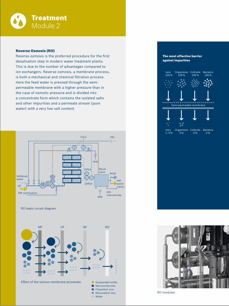
RO basic circuit diagram
Reverse Osmosis (RO) Reverse osmosis is the preferred procedure for the first desalination step in modern water treatment plants. This is due to the number of advantages compared to ion exchangers. Reverse osmosis, a membrane process, is both a mechanical and chemical filtration process. Here the feed water is pressed through the semi- permeable membrane with a higher pressure than in the case of osmotic pressure and is divided into a concentrate form which contains the isolated salts and other impurities and a permeate stream (pure water) with a very low salt content.
HW sanitisation
ROW
HW saniti-sation
EDI concentrate
WW
WW
PW
Suspended solids Macromolecules Polyvalent ions Monovalent ions Water
MF UF NF RO
Effect of the various membrane processes
The most effective barrier against impurities
Block valve
FICA
QIRSA
TIRSA
SIC
EUPI
Softened water
Ions 100 %
Organisms 100 %
Colloids100 %
Bacteria100 %
Ions 1–5 %
Organisms 5 %
Colloids0 %
Bacteria0 %
Semi-permeable membrane
RO modules

Treatment – Module 2 | 7
Reverse osmosis (RO)
RO modules
Production output Min. 0,22 0,55 1,10 1,40 1,65 2,80 3,30 4,20 4,95 6,60 8,25
[m3/h] Nominal 0,44 1,10 2,00 2,80 3,30 5,60 6,60 8,40 9,90 13,20 16,45
Max. 0,66 1,65 3,10 4,20 5,11 8,40 10,22 12,60 15,33 22,44 25,55
Plant dimensions*Width (front) 3.100 3.100 3.600 3.600 3.600 3.800 3.800 3.800 3.800 5.150 5.500
[in mm] Depth 1.700 1.700 1.700 1.700 1.700 1.680 1.680 1.680 1.680 1.680 1.680
Height 2.160 2.160 2.160 2.160 2.160 2.160 2.160 2.160 2.160 2.300 2.300
Softener dimensions*[in mm], data without salt receiver tank
Width (front) 2.000 2.000 2.000 2.000 2.000 2.000
Depth 1.530 1.530 1.530 1.530 1.630 1.630
Height 2.675 2.675 2.675 2.675 2.675 2.675
PW 1
6500
H
PW 1
3300
H
PW 9
900
H
PW 8
400
H
PW 6
600
H
PW 5
600
H
PW 3
300
H
PW 2
800
H
PW 2
000
H
PW 1
100
H
PW 4
00 HDimensions for the hot water
sanitisable PW plants (RO, EDI)
Integrated into the entire system
RO modules * The dimensions can vary due to technical modifications.

Treatment Module 2
Electrodeionization (EDI)The downstream electrodeionisation (EDI), an electro-chemical process, produces a diluate which easily fulfils the requirements for purified water with a large quality reserve. The driving force in this procedure is a constant electrical field which brings the loaded water substances to move around in the chambers by means of the ion exchange resin. The spreading of the electric field also causes the separation of the water into hydro-gen and hydroxide ions which continuously regenerate the ion exchange resin. The ions are transported to the respective concentrate chambers and conducted away. The diluate (ultrapure water) is conveyed to storage. EDI systems stand out for being unsusceptible to variations in the composition of the feed water and apart from the reduction of the salt content, CO2, SiO2 and TOC are also reduced by over 90 %.
EDI basic circuit diagram
Quality parameters for purified water EDI stacks
DegasificationThe CO2, a gas which freely occurs in the feed water, cannot be separa-ted with reverse osmosis and thus increases the conductivity of the permeate. So it segregates and can be conveyed as a precipitable bicarbonate (HCO3), pH regulated sodium hydroxide (NaOH) is added before the reverse osmosis.
As a more refined procedure, nowadays the CO2 is increasingly reduced without using chemicals via membrane degasification. Membrane contactors with hydro-phobic hollow fibre membranes are used. The reduction takes place in a purely physical way according to the membrane diffusion process through the spreading of a partial pressure gradient. These measures unload the downstream EDI plant.
Parameters EP (Bulk) USP (Bulk)
TOC (Total Organic Carbon) [ppb C] < 500 < 500
Conductivity [20 °C µS/cm] < 4,3 –
Conductivity [25 °C µS/cm] – < 1,3
Nitrate [ppm] < 0,2 –
Heavy metals [ppm as Pb] < 0,1 –
Total microbial count [KBE/ml] < 100 < 100
to RO
Block valve
Effluent
Sample
Sample
EDIAir
PW
ROW
Membrane degasifi-cation Pi
EDI
Pi
FICA
PIRA
Pi
FICA
FICA
Sample
PW
TIRSA
QIRSA
PW

Treatment – Module 2 | 9
Electrodeionization (EDI)
EDI modules
– – Cathode – –
+ + Anode + +
Feed water Concentrate
Cl–SO4
– HCO3– CO3
–
HSiO2– OH–
Na+
Mg++Ca++ Na+H+SO4
–
Cl–
Permeate
Diluate(purified water)
Cl–
HCO3–
Na+
CO2
SiO2
Mg++
Ca++
H2OSO4
–
H2O
Cationic exchanger membrane
Anion exchanger membrane
Basic circuit diagram of the EDI process

Final cleaning Module 3
UF basic circuit diagram
UltrafiltrationUltrafiltration (UF) is a membrane separating process for separating particular impurities or solute substances due to the molecular weight or the size (sieve effect). In the pharmaceutical sector, hollow fibre polysulphone membranes with a separation limit of 6000 Daltons are used – a separation limit which is far below the size of the impurities to be removed such as bacteria, viruses and pyrogens. In the ultrafiltration plant, the influent water which fulfils the requirements in terms of conductivity and TOC value is further treated to become apyrogenic and sterile water. The integrity of the UF modules can be tested with an in situ bubble test, i. e. in the plant. UF plants can also be sanitised with hot water (80° C). Here a reliable and largely more cost-efficient process is available (compared to distillation) which produces highly purified water (HPW) from the purified water.
Quality parameters for highly purified water
Parameters EP (Bulk) USP (Bulk)
TOC (Total Organic Carbon) [ppb C] < 500 n.a.
Conductivity [20°C µS/cm] < 1,1 n.a.
Nitrate [ppm] < 0,2 n.a.
Heavy metals [ppm as Pb] < 0,1 n.a.
Total microbial count [KBE/100 ml] < 10 n.a.
Bacterial endotoxins [EU/ml] < 0,25 n.a.
to RO
Block valve
Sample
Pi
Pi
Pi
Effluent
HPWstorage
tank
HPW
TIRSA
QIRSA
Use of high performance plastics such as PVDFThe UF modules are integrated into the system by using PVDF piping components. Through the special WNF welding technology, the highest level of safety is guaranteed with regard to emptying residue. The connections are smooth, are not misaligned and also have the same material properties as the modules. In addition to the piping components, block valves in the same material are also available.
UF modules

Final cleaning – Modul 3 | 11
Ultrafiltration (UF)
Continuous ultrafiltration via hollow fibre modules
At a glance
Modular structure fully premounted plant sections (module 1 to 3)
Construction in one, or upon request, divided plant sections
Compact user and service friendly construction Tested ready for connection and prequalified Sanitisation through hot water treatment or
chemical treatment Block valve technology in the lowest dead space design Market standard individual components available
worldwide Automation concept based on Siemens S7 with
WinCC flexible as standard software design

Fab
er &
Mo
lden
hau
er 2
6941
| 1
00%
ch
lori
ne
free
pap
er |
Pri
nted
in G
erm
any
Pharmatec GmbHA Bosch Packaging Technology Company
Elisabeth-Boer-Straße 3 01099 Dresden GermanyTel. +49 351 2 82 78-0Fax +49 351 2 82 78-662www.pharmatec.de