ph-reversed ionic current rectification displayed by conically shaped nanochannel without any...
TRANSCRIPT
Dynamic Article LinksC<Nanoscale
Cite this: Nanoscale, 2011, 3, 3767
www.rsc.org/nanoscale PAPER
Publ
ishe
d on
08
Aug
ust 2
011.
Dow
nloa
ded
by S
tate
Uni
vers
ity o
f N
ew Y
ork
at S
tony
Bro
ok o
n 25
/10/
2014
04:
12:1
7.
View Article Online / Journal Homepage / Table of Contents for this issue
pH-Reversed ionic current rectification displayed by conically shapednanochannel without any modification†
Zhijun Guo, Jiahai Wang,* Jiangtao Ren and Erkang Wang*
Received 28th April 2011, Accepted 17th June 2011
DOI: 10.1039/c1nr10434a
Ion current through a nascent nanochannel with conically shaped geometry in PET (polyethylene
terephthalate) membrane sandwiched between two same buffer solutions at pH # 3 was routinely
considered to exhibit no rectification and, if any, much weaker rectification than that for a nanochannel
with a negative surface charge, since the surface charge on the membrane decreases to zero along with
decreasing the pH value of the buffer solution down to the pKa of carboxylic acid. However, in this
study, we discovered that in the buffer solution with low ionic strength at pH values below 3, the
conically shaped nanochannels exhibited distinct ion current rectification, as expected for nanochannels
with a positive surface charge, if voltages beyond �2V range were scanned. We reasoned that the
current rectification engendered by the positive surface charge of a conical nanochannel was due to
further protonation of the hydrogen bonded hydrogel layer or neutral carboxylic acid inside the
nanochannel. Therefore, our results enrich the knowledge about nanochannel technology and indicate
that a nanofluidic diode based on pH-reversed ion current rectification through a conical nanochannel
can be achieved without any modification of the PET membrane.
1. Introduction
A track-etching technique has been widespread in recent years
used for fabrication of ‘‘abiotic’’ asymmetric conically shaped
nanochannels,1–11 which have been proved to be a versatile
platform for biosensor and single molecule analysis. The asym-
metric nanochannels possess analogous functions to a biological
protein ion channel,12–19 such as ion selectivity, current rectifi-
cation, current fluctuation and current switch. On the basis of
these outstanding physicochemical properties of asymmetric
nanochannels embedded in the membrane, a series of investiga-
tions have been dedicated into looking for new tools for engi-
neering these nanochannels with new functionalities similar to
those of biological protein nanopores, and constructing nano-
fluidic devices by manipulating the ionic transport characteristics
of conical nanochannels.8,20–25
Nanofluidic devices with tuned ionic selectivity and current
rectification are extremely interesting, because they are respon-
sive to user input and environmental surroundings, which is
needed in real applications. The first example reported by Wei,
Bard, and Feldberg in 1997 has demonstrated that a conically
State Key Laboratory of Electroanalytical Chemistry, Changchun Instituteof Applied Chemistry, Chinese Academy of Sciences, Graduate School ofthe Chinese Academy of Sciences, Changchun, 130022, Jilin, PR China.E-mail: [email protected]; [email protected]
† Electronic supplementary information (ESI) available: SEM images ofmulti-tracked nanochannel fabricated from a surfactant-protectedone-step etching method. See DOI: 10.1039/c1nr10434a
This journal is ª The Royal Society of Chemistry 2011
shaped glass nanopipette rectified current with non-ohmic ion
transport,26 which sparked intensive research in this area.27–41
Later, several other groups have demonstrated that a conically
shaped nanochannel embedded in a polymer membrane had the
same ion transport characteristics when transmembrane poten-
tial difference was applied.5,6,42,43 The conically shaped nano-
channel can also be made intelligent by functionalization of the
nanochannel with a series of chemical groups, such as DNA,44,45
polymer brush9,21 and protein.24 For example, Jiang’s group have
reported a series of smart nanochannel devices which are
responsive to different stimuli,46–48 such as pH,49 potassium ion50
and temperature.4
Among those investigations focusing on nanochannels in
polymer membranes,3,4,9,20–24,42,51,52 the PET membrane has been
used to investigate the physical basis of ion transport across
a biomimetic nanochannel embedded in the membrane, due to its
dramatic advantages as compared to others. Firstly, the ease of
etching a heavy ion track in the PET membrane only entails
placing sodium hydroxide on one side53 or on both sides of the
membrane.1 Secondly, the etching process can be closely moni-
tored via recording currents; therefore, the small opening of the
nanochannel can be adjusted at will by stopping the etching
process at a desired current value corresponding to the expected
diameter of the small opening of a conically shaped nanochannel.
Finally, the surface of PET after etching using high concentra-
tion of sodium hydroxide is ended with a carboxyl group, which
facilitates further functionalization of the inner channel wall. In
combination with other various tools, various methods have
Nanoscale, 2011, 3, 3767–3773 | 3767
Publ
ishe
d on
08
Aug
ust 2
011.
Dow
nloa
ded
by S
tate
Uni
vers
ity o
f N
ew Y
ork
at S
tony
Bro
ok o
n 25
/10/
2014
04:
12:1
7.
View Article Online
been reported to chemically modify the surface wall of the
nanochannel to tune the ion transport. The Martin group has
invented a gold plating method to deposit a gold nanotube inside
the nanochannels in the membrane, followed by modification
with cysteine whose charge polarity can be switched by pH.54 By
finely adjusting the pH values, the transporting properties can be
modulated. Alternative methods by using EDC/NHS coupling
agent have also been utilized to efficiently functionalize the
nanochannel with interesting functional groups.1,4,20,43 In addi-
tion to the chemical modification of the nanochannel wall with
charged groups, polyvalent ions have been demonstrated to
reversibly bind a carboxyl group on the nanochannel wall,
resulting in the reversal of the surface charge such that the
current flow and current rectification can be adjusted without
any chemical modification.3 Adsorption of a hydrophobic drug
with positive charge polarity onto the tip side of the nanochannel
has also been reported to induce the local charge inversion in the
nanpore wall, leading to switching of the ionic selectivity of the
nanochannel from a positive ion to a negative ion.7
In this study, we demonstrated that even without chemical
functionalization and existence of polyvalent ions (or hydro-
phobic molecules), a synthetic conical nanochannel in the PET
membrane exhibited current rectifications in the solution at pH
# 3 as expected for the conical nanochannels with a positively
charged surface. As is well known, ion current through a coni-
cally shaped nanochannel in the PET membrane sandwiched
between two same solutions at pH # 3 was routinely considered
to exhibit no rectification and if any, much weaker rectification
than that for a negatively charged surface, since the surface
charge on the membrane is neutralized along with decreasing the
pH value of the buffer solution down to the pKa of carboxylic
acid. However, in this study, we discovered that in solutions at
pH # 3, the conically shaped nanochannels exhibited distinct
positive ionic-current rectification, if voltages beyond �2V range
were scanned. We reasoned that the positive current rectification
engendered by the positive charge of the surface of the conical
nanochannel was due to further protonation of the hydrogen
bonded hydrogel layer or neutral carboxylic acid inside the
nanochannel.55–58 Therefore, pH-reversed ionic-current rectifi-
cation of a conical nanochannel can be achieved without any
modification of the PET membrane.
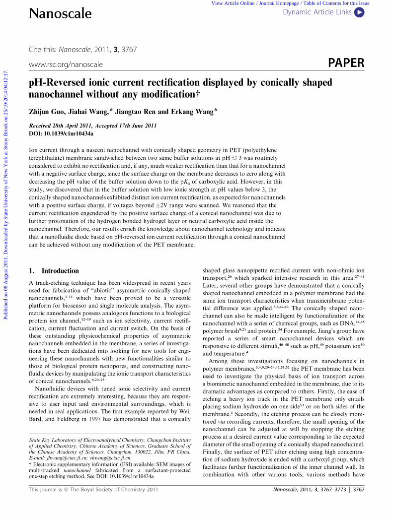
Fig. 1 (a) Scanning electron microscopy of the base side of the conical
nanochannel in a PET membrane via the two-step etching method. (b)
Schematic illustration of switching the current–voltage curve in response
to the reversal of charge polarity in the nanochannel.
2. Experimental
Materials
PET (polyethylene terephthalate) membranes (diameter ¼ 3 cm,
thickness ¼ 12 mm) that had been irradiated with a heavy ion of
2.2 GeV kinetic energy to create a single damage track through
the membrane were obtained from GSI, Darmstadt, Germany
and referred to as ‘‘tracked’’ membranes. Tetrakis (diisopro-
pylguanidino)zinc phthalocyanine (Zn-DIGP) was provided by
Prof. NathanW. Luedtke, University of Zurich.59 The surfactant
DOWfax 2A1 was purchased from DOW Chemical. Sodium
chloride (NaCl) and potassium chloride (KCl) were purchased
from Beijing Chemical Reagent Company (Beijing, China). All
of the chemicals were at least analytical grade. The water used
throughout all experiments was purified by a Milli-Q system
(Millipore, Bedford, MA, USA).
3768 | Nanoscale, 2011, 3, 3767–3773
Nanochannel fabrication
Nanochannels with a tip diameter of 1.5 nm and 3 nm were
fabricated with two-step etching described by the Martin group
for reproducibly preparing conically shaped nanochannels in
tracked poly(ethylene terphthalate) membranes.60 Each side of
the tracked PET membrane was irradiated under UV light
(365 nm) for 1 h, and then the membrane was mounted in a two-
compartment cell such that the electrolyte solution could be
placed on either side of the tracked membrane. The first etch step
entailed placing an etching solution (9M NaOH) on one side of
the membrane and a stopping solution that neutralizes the
etchant (1M HCOOH and 1M KCl) on the other side. The
temperature during etching was maintained at 20 �C. Each half
cell contained a Pt wire (dia ¼ 0.1 cm, length �5 cm), and
a Keithley 2635A picoammeter/voltage-source (Keithley Instru-
ments, Cleveland, OH) was used to apply a transmembrane
potential of 1 V during etching and measure the resulting current
ionic flowing through the nascent nanochannel. This first etch
step was terminated when the current increased up to 0.1 nA. The
stop solution was placed in both half cells to neutralize the
etchant solution. According to a previous procedure, the diam-
eter of the base opening after the first etch step was determined
by obtaining scanning electron micrographs of the base side of
multi-tracked PET membranes (1 � 108 tracks cm�2) etched
under the same conditions. These studies yielded an etch rate of
2.3 nm min�1. The tip diameter was finely tuned by using
a second etch step. The second etch step entailed placing the 1M
NaOH etch solution on both sides of the membrane. A trans-
membrane potential of 1 V was applied. The etch step was
stopped once the desired current corresponding to a certain tip
diameter was reached.
Nanochannels with a tip diameter of 30 nm were fabricated
using the surfactant-protected one-step etching method
described by Ali for preparing conically shaped nanochannels in
tracked poly(ethylene terphthalate) membranes.1 The protecting
solution (6 MNaOH + 0.07% 2A1) was placed on one side of the
membrane, 6 M sodium hydroxide solution was placed on the
UV-treated side to control the diameter of the big opening of the
nanochannel. During the etching process, temperature was
maintained at 40 �C. When the desired current was reached, 1 M
HCl solution was placed on both sides of the membrane to stop
the etching process. The other procedures were the same as those
for the two-step etching method.
This journal is ª The Royal Society of Chemistry 2011
Publ
ishe
d on
08
Aug
ust 2
011.
Dow
nloa
ded
by S
tate
Uni
vers
ity o
f N
ew Y
ork
at S
tony
Bro
ok o
n 25
/10/
2014
04:
12:1
7.
View Article Online
Fig. 1(a) shows a SEM image of the base side of a multi-
tracked membrane, and the average diameter (D) of the base side
is 550 nm. The tip diameter (d) after the second etching was
measured using the electrochemical method described in detail
previously. The following equation was used to calculate the tip
diameter:
d ¼ 4LI/pDkV
where L is the membrane thickness, k is the conductivity of the
electrolyte, V is the transmembrane voltage, and I is the ionic
current. The equation provides a solution to obtaining the tip
diameter of an ideal conically shaped nanochannel. However, the
tip diameter cannot be directly imaged by the current techniques;
therefore, a rough estimation of the tip diameter has to be used.
The diameter of the nanochannel with surfactant protected
etching was obtained in the same way as with the two-step
etching method.
Current–voltage measurement
To verify the successful fabrication of conically shaped nano-
channels, an electrochemical measurement was carried out to
characterize the current rectification which is an intriguing
feature of the nascent nanochannel. Two silver/silver chloride
electrodes were immersed on the tip side and the base side of the
nanochannel, respectively. The current–voltage curves of an
asymmetrical conical nanochannel were obtained by applying
transmembrane potential differences in various buffer solutions.
The current–voltage curves of the as-prepared nanochannel after
adsorption of Zn-DIGP were measured in 20 mM phosphate
buffered solution containing 10 mM KCl, as shown in Fig. 2.
3. Results and discussion
Nanoscale control of the surface charge in the nanochannel has
been assessed as an effective method to modulate the ion trans-
port through nanochannels and current rectification of nano-
channels.3 From all the studies involving nanochannels with
surface modification and without modification, they showed that
current rectification was very sensitive to the nanochannel charge
and slight variation of the surface charge can trigger a distinct
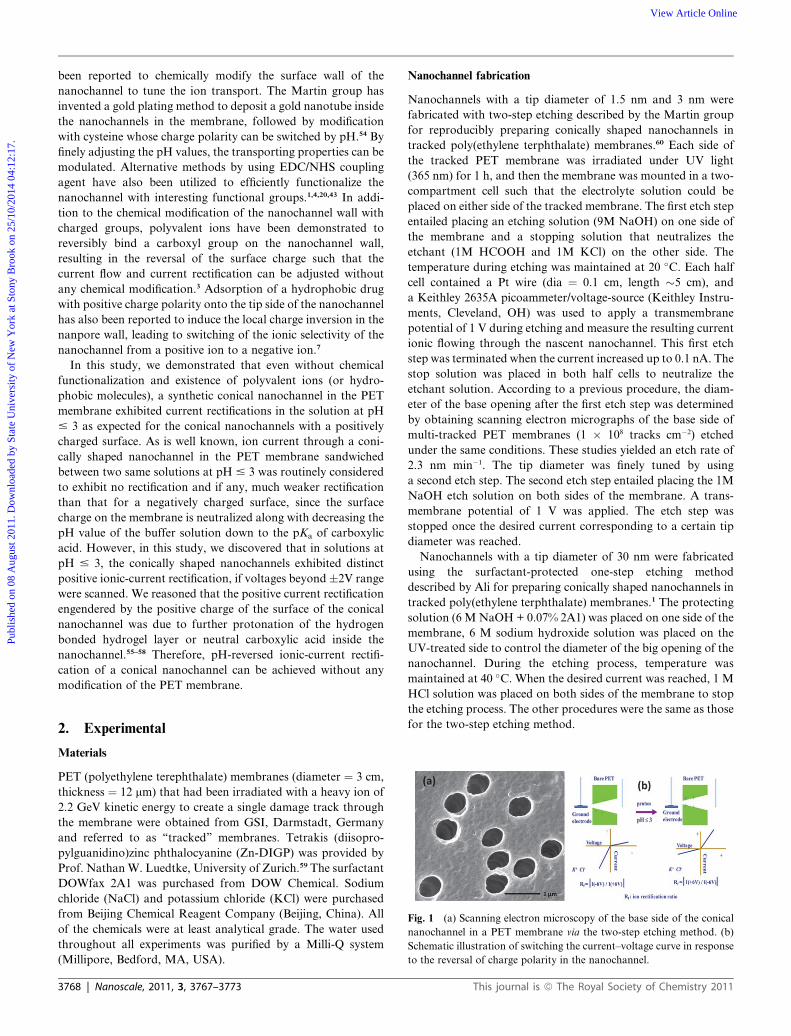
Fig. 2 (a) Zn-DIGP; (b) current–voltage curves of the nanochannel in
the presence of 2mM Zn-DIGP (red circle) and in the absence of Zn-
DIGP (black square), the small molecules were dissolved in 20 mM PBS
buffer solution (pH 9) containing 10 mM KCl. The diameters of the
narrow opening and the big opening of the nanochannel are 1.5 nm and
550 nm, respectively.
This journal is ª The Royal Society of Chemistry 2011
change of the current rectification.61 Therefore, the current
rectification of the nanochannel is a paramount indicator of
successful engineering of the inside of a conically shaped nano-
channel and the sign of a surface charge. As shown in Fig. 1(b),
the ground electrode is placed on the tip side of the nanochannel
and the ion current rectification is dictated by the sign of the
surface charge: a synthetic conical nanochannel with a negatively
charged surface rectify the current such that the ion current
flowing at a negative applied potential overwhelms the ion
current flowing at a positive applied potential, the current is
mainly carried by cations (Fig. 1(b)); a synthetic conical nano-
channel with a positively charged surface rectifies the current
such that the ion current flowing at a positive applied potential
overwhelms the ion current flowing at a negative applied
potential, the current is mainly carried by anions (Fig. 1(b)). A
large current exhibited by asymmetrical nanochannel with posi-
tive surface charge (or negative surface charge) is referred to as
‘‘on’’ state and a small current is referred to as ‘‘off’’ state. Ion
current rectification (Rf) which describes the ion selectivity of
a conical nanochannel can be defined as the absolute ratio of the
current for an ‘‘on‘‘ state to the current for an ‘‘off‘‘ state
measured at the same absolute value of the voltage but of
opposite polarity.
In order to verify the successful fabrication of a nanochannel
in a PET membrane, the PET foil after asymmetrical etching was
sandwiched between two compartments containing buffer solu-
tion and transmembrane potentials from �6 V to +6 V were
scanned with steps of 0.15 v/s. The current–voltage curve
obtained from the nascent nanochannel with a tip diameter of
1.5 nm has the same characteristics as expected for an asym-
metrical nanochannel grafted with a carboxylic group (Fig. 2(b),
black curve). The current–voltage curve shows an ‘‘on’’ state at
a negatively applied potential and shows an ‘‘off’’ state at
a positively applied potential. After replacing the buffer solution
(20 mM PBS with pH 9, 10 mM KCl) with the same buffer
solution containing 2mM Zn-DIGP (Fig. 2(a), red curve), the
shape of the current–voltage curve was almost reversed, with the
nonlinear profile featuring the asymmetrical conically shaped
nanochannel with a positive surface charge, revealing that the
negative surface charge on the surface of the nanochannel was
overcompensated by adsorbing a positively charged Zn-DIGP
onto the inner surface of the nanochannel. It has been proven
that adsorption of a hydrophobic drug with positive charge
polarity onto the tip side of the nanochannel induced local
charge inversion in the nanpore wall, leading to switching of the
ion selectivity of the nanochannel from a positive ion to a nega-
tive ion.7 Therefore, the nanochannel we fabricated herein
possessed the unique characteristics of an asymmetrical conically
shaped nanochannel: a positively charged nanochannel was
selective to anions, a negatively charged nanochannel was
selective to cations.
The conically shaped nanochannel with a carboxylic group has
long been reported to be responsive to the pH values. At pH close
to the pKa value (3.8) of a carboxylic group on the surface of
PET,62 it has been reported that the surface charge was dimin-
ished, leading to a linear I–V curve of the membrane containing
a conically shaped nanochannel with the neutral surface. At pH
above this isoelectric point, the surface charge is negative due to
deprotonation of the carboxylic group, leading to a nonlinear
Nanoscale, 2011, 3, 3767–3773 | 3769
Publ
ishe
d on
08
Aug
ust 2
011.
Dow
nloa
ded
by S
tate
Uni
vers
ity o
f N
ew Y
ork
at S
tony
Bro
ok o
n 25
/10/
2014
04:
12:1
7.
View Article Online
I–V curve. It has to be noted that in most cases,1,6 salt concen-
tration above 0.1MKCl has been used to measure the I–V curves
of the nanochannel in solutions at pH values close to the pKa
value of a carboxylic group and to construct various nano-
channel devices. In this way, important information regarding
the surface property of the nascent nanochannel may be omitted
due to a small debye length under high concentration of salt,
especially for nanochannel with a weakly charged surface.
Therefore, for our experiments with the nanochannel obtained
through the two-step etching method, we adopted various buffer
solutions containing 10 mM KCl (10 mM PBS or 10 mM Tris-
HCl or 10 mM HEPES), which was adjusted to different pH
values by concentrated HCl.
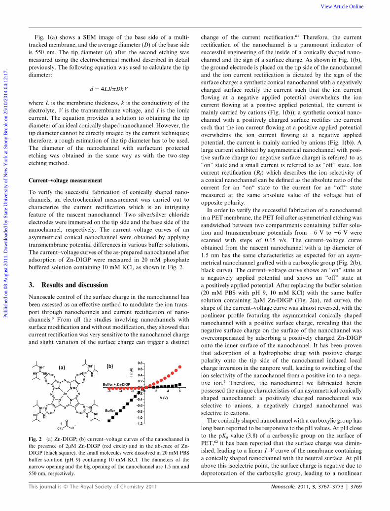
As shown in Fig. 3(a), the I–V curves obtained from a nano-
channel with a tip diameter of 3 nm show that at a voltage scan
range from �1 V to 1 V, the nanochannel being immersed in
20 mM PBS buffered solution at pH 9 (or pH 5) revealed the
characteristics of a nanochannel with a negative surface charge,
which was consistent with those found in previous reports for
a negatively charged surface;3,6 when the membrane was
immersed in 20 mM PBS buffer with pH 3, the I–V curve of the
nanochannel became linear at the same voltage range, illustrating
that the negative surface charge was diminished as compared to
the case at pH 9 (or pH 5). Most interestingly and contrary to
previous studies, when we gradually extended the scan range
beyond �1V (Fig. 3(b)–3(f)), nonlinear I–V curves for nano-
channel in PET membrane sandwiched between buffer solution
Fig. 3 Current–voltage curves of the nanochannel with a scan range
from�1 V to 1 V (a),�2 V to 2 V (b),�3 V to 3 V (c),�4 V to 4 V (d),�5
V to 5 V (e) and �6 V to 6 V (f), respectively. Buffer solutions at various
pH values of 3 (black square), 5 (red circle) and 9 (blue triangle), con-
taining 20 mM PBS and 10 mM KCl; the diameters of the narrow
opening and the big opening of the nanochannel are 3 nm and 550 nm,
respectively.
3770 | Nanoscale, 2011, 3, 3767–3773
at pH 3, showed up with features as expected for a positive
surface charge, revealing that the impact of a weakly charged
surface in the nanochannel on ion current transport can only be
observed at a higher transmembrane potential. Therefore, three
requirements have to be met before observation of the impact of
a weakly charged surface on the ion transport of the nano-
channel: large voltage scan range, proper ionic strength and
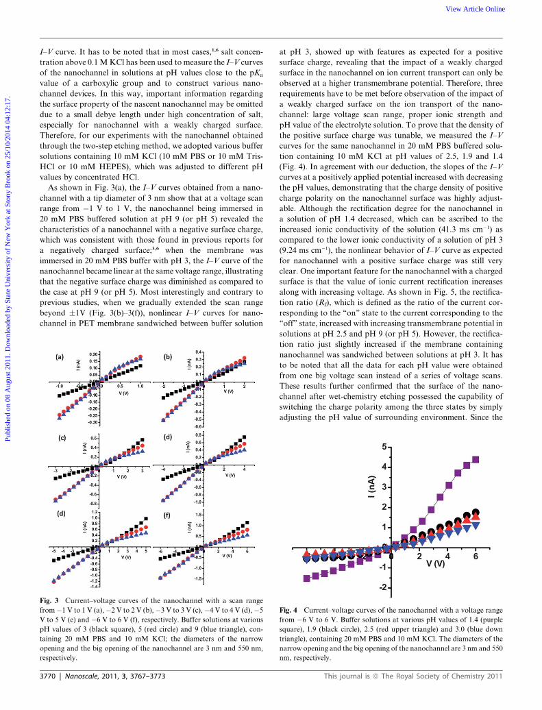
pH value of the electrolyte solution. To prove that the density of
the positive surface charge was tunable, we measured the I–V
curves for the same nanochannel in 20 mM PBS buffered solu-
tion containing 10 mM KCl at pH values of 2.5, 1.9 and 1.4
(Fig. 4). In agreement with our deduction, the slopes of the I–V
curves at a positively applied potential increased with decreasing
the pH values, demonstrating that the charge density of positive
charge polarity on the nanochannel surface was highly adjust-
able. Although the rectification degree for the nanochannel in
a solution of pH 1.4 decreased, which can be ascribed to the
increased ionic conductivity of the solution (41.3 ms cm�1) as
compared to the lower ionic conductivity of a solution of pH 3
(9.24 ms cm�1), the nonlinear behavior of I–V curve as expected
for nanochannel with a positive surface charge was still very
clear. One important feature for the nanochannel with a charged
surface is that the value of ionic current rectification increases
along with increasing voltage. As shown in Fig. 5, the rectifica-
tion ratio (Rf), which is defined as the ratio of the current cor-
responding to the ‘‘on’’ state to the current corresponding to the
‘‘off’’ state, increased with increasing transmembrane potential in
solutions at pH 2.5 and pH 9 (or pH 5). However, the rectifica-
tion ratio just slightly increased if the membrane containing
nanochannel was sandwiched between solutions at pH 3. It has
to be noted that all the data for each pH value were obtained
from one big voltage scan instead of a series of voltage scans.
These results further confirmed that the surface of the nano-
channel after wet-chemistry etching possessed the capability of
switching the charge polarity among the three states by simply
adjusting the pH value of surrounding environment. Since the
Fig. 4 Current–voltage curves of the nanochannel with a voltage range
from �6 V to 6 V. Buffer solutions at various pH values of 1.4 (purple
square), 1.9 (black circle), 2.5 (red upper triangle) and 3.0 (blue down
triangle), containing 20 mM PBS and 10 mM KCl. The diameters of the
narrow opening and the big opening of the nanochannel are 3 nm and 550
nm, respectively.
This journal is ª The Royal Society of Chemistry 2011
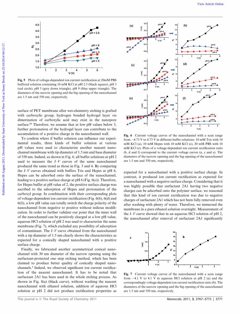
Fig. 5 Plots of voltage-dependent ion current rectification at 20mMPBS
buffered solution containing 10 mM KCl at pH 2.5 (black square), pH 3
(red circle), pH 5 (grey down triangle), pH 9 (blue upper triangle). The
diameters of the narrow opening and the big opening of the nanochannel
are 1.5 nm and 550 nm, respectively.
Fig. 6 Current–voltage curves of the nanochannel with a scan range
from �4.73 V to 4.73 V in different buffer solutions: 10 mM Tris with 10
mM KCl (a), 10 mM Hepes with 10 mM KCl (c), 20 mM PBS with 10
mM KCl (e). Plots of a voltage-dependent ion current rectification ratio
(b, d and f) correspond to the current–voltage curves (a, c and e). The
diameters of the narrow opening and the big opening of the nanochannel
are 1.5 nm and 550 nm, respectively.
Fig. 7 Current–voltage curves of the nanochannel with a scan range
from �4.1 V to 4.1 V in aqueous HCl solution at pH 2 (a) and the
correspondingly voltage-dependent ion current rectification ratio (b). The
diameters of the narrow opening and the big opening of the nanochannel
are 1.5 nm and 550 nm, respectively.
Publ
ishe
d on
08
Aug
ust 2
011.
Dow
nloa
ded
by S
tate
Uni
vers
ity o
f N
ew Y
ork
at S
tony
Bro
ok o
n 25
/10/
2014
04:
12:1
7.
View Article Online
surface of PET membrane after wet-chemistry etching is grafted
with carboxylic group, hydrogen bonded hydrogel layer via
dimerization of carboxylic acid may exist in the nanopore
surface.63 Therefore, we assume that at low pH values below 3,
further protonation of the hydrogel layer can contribute to the
accumulation of a positive charge in the nanochannel wall.
To confirm where if buffer solution can influence our experi-
mental results, three kinds of buffer solution at various
pH values were used to characterize another nascent nano-
channel membrane with tip diameter of 1.5 nm and base diameter
of 550 nm. Indeed, as shown in Fig. 6, all buffer solutions at pH 2
used to measure the I–V curves of the same nanochannel
produced the same trend as those in Fig. 3 and 4. By comparing
the I–V curves obtained with buffers Tris and Hepes at pH 6,
Hepes can be adsorbed onto the surface of the nanochannel,
leading to a positive surface charge at pH 6 (Fig. 6(c)). Therefore,
for Hepes buffer at pH value of 2, the positive surface charge was
ascribed to the adsorption of Hepes and protonation of the
carboxyl group. In combination with their corresponding plots
of voltage-dependent ion current rectification (Fig. 6(b), 6(d) and
6(f)), a low pH value can totally switch the charge polarity of the
nanochannel from negative to positive without tedious modifi-
cation. In order to further validate our point that the inner wall
of the nanochannel can be positively charged at a low pH value,
aqueous HCl solution of pH 2 was used to characterize the same
membrane (Fig. 7), which excluded any possibility of adsorption
of contaminant. The I–V curve obtained from the nanochannel
with a tip diameter of 1.5 nm clearly shows the characteristics as
expected for a conically shaped nanochannel with a positive
surface charge.
Finally, we fabricated another asymmetrical conical nano-
channel with 30 nm diameter of the narrow opening using the
surfactant-protected one–step etching method, which has been
claimed to produce better quality of conically shaped nano-
channels.1 Indeed, we observed significant ion current rectifica-
tion of the nascent nanochannel. It has to be noted that
surfactant 2A1 has been used in the whole etching process. As
shown in Fig. 8(a) (black curve), without washing the nascent
nanochannel with ethanol solution, addition of aqueous HCl
solution at pH 2 did not produce rectification properties as
This journal is ª The Royal Society of Chemistry 2011
expected for a nanochannel with a positive surface charge. In
contrast, it produced ion current rectification as expected for
a nanochannel with a negative surface charge. Considering that it
was highly possible that surfactant 2A1 having two negative
charges can be adsorbed onto the polymer surface, we reasoned
that this kind of ion current rectification was due to negative
charges of surfactant 2A1 which has not been fully removed even
after washing with plenty of water. Therefore, we immersed the
membrane in a pure ethanol solution overnight. Measurement of
the I–V curve showed that in an aqueous HCl solution of pH 2,
the nanochannel after removal of surfactant 2A1 significantly
Nanoscale, 2011, 3, 3767–3773 | 3771
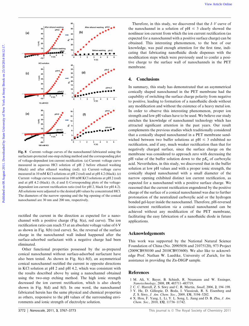
Fig. 8 Current–voltage curves of the nanochannel fabricated using the
surfactant-protected one-step etching method and the corresponding plot
of voltage-dependent ion current rectification. (a) Current–voltage curve
measured in aqueous HCl solution of pH 2 before ethanol washing
(black) and after ethanol washing (red). (c) Current–voltage curve
measured in 10 mMKCl solutions at pH 2 (red) and at pH 4.2 (black). (e)
Current–voltage curves measured in 100 mMKCl solutions at pH 2 (red)
and at pH 4.2 (black). (b, d and f) Corresponding plots of the voltage-
dependent ion current rectification ratio (red for pH 2, black for pH 4.2).
All solutions were adjusted to the desired pH values by concentrated HCl.
The diameters of the narrow opening and the big opening of the conical
nanochannel are 30 nm and 200 nm, respectively.Publ
ishe
d on
08
Aug
ust 2
011.
Dow
nloa
ded
by S
tate
Uni
vers
ity o
f N
ew Y
ork
at S
tony
Bro
ok o
n 25
/10/
2014
04:
12:1
7.
View Article Online
rectified the current in the direction as expected for a nano-
channel with a positive charge (Fig. 8(a), red curve). The ion
rectification ratio can reach 53 at an absolute voltage value of 6 V
as shown in Fig. 8(b) (red curve). So, the reversal of the surface
charge in the nanochannel wall indeed happened after the
surface-adsorbed surfactant with a negative charge had been
eliminated.
Other functional properties possessed by the as-prepared
conical nanochannel without surface-adsorbed surfactant have
also been tested. As shown in Fig. 8(c)–8(f), an asymmetrical
conical nanochannel rectified the current in opposite directions
in KCl solution at pH 2 and pH 4.2, which was consistent with
the results described above by using a nanochannel obtained
using the two-step etching method. The high ionic strength
decreased the ion current rectification, which is also clearly
shown in Fig. 8(d) and 8(f). In one word, the nanochannel
fabricated herein has the same physical and chemical properties
as others, responsive to the pH values of the surrounding envi-
ronments and ionic strength of electrolyte solution.
3772 | Nanoscale, 2011, 3, 3767–3773
Therefore, in this study, we discovered that the I–V curve of
the nanochannel in a solution of pH # 3 clearly showed the
nonlinear ion current from which the ion current rectification (as
expected for a nanochannel with a positive surface charge) can be
obtained. This interesting phenomenon, to the best of our
knowledge, was paid enough attention for the first time, indi-
cating that fabricating nanofluidic diode dispenses with the
modification steps which were previously used to confer a posi-
tive charge to the surface wall of nanochannels in the PET
membrane.
4. Conclusions
In summary, this study has demonstrated that an asymmetrical
conically shaped nanochannel in the PET membrane had the
capability of switching the surface charge polarity from negative
to positive, leading to formation of a nanofluidic diode without
any modification and without the existence of a heavy metal ion.
In order to observe this interesting phenomenon, proper ion
strength and low pH values have to be used. We believe our study
enriches the knowledge of nanochannel technology which has
attracted significant attention in the past years. Our result
complements the previous studies which traditionally considered
that a conically shaped nanochannel in a PET membrane sand-
wiched between two buffer solutions at pH # 3 exhibited no
rectification, and if any, much weaker rectification than that for
negatively charged surface, since the surface charge on the
membrane was considered to approach zero with decreasing the
pH value of the buffer solution down to the pKa of carboxylic
acid. Nevertheless, in this study, we discovered that in the buffer
solution at low pH values and with a proper ionic strength, the
conically shaped nanochannel with a small diameter of the
narrow opening exhibited distinct ion current rectification, as
expected for a nanochannel with a positive surface charge. We
reasoned that the current rectification engendered by the positive
charge of the surface of a conical nanochannel was due to further
protonation of the neutralized carboxylic acid or the hydrogen
bonded gel-layer inside the nanochannel. Therefore, pH-reversed
ionic-current rectification via a conical nanochannel can be
achieved without any modification of the PET membrane,
facilitating the easy fabrication of a nanofluidic diode in future
applications.
Acknowledgements
This work was supported by the National Natural Science
Foundation of China (No. 20905056 and 21075120), 973 Project
(2009CB930100 and 2010CB933600). We also like to acknowl-
edge Prof. Nathan W. Luedtke, University of Zurich, for his
assistance in providing the Zn-DIGP sample.
References
1 M. Ali, V. Bayer, B. Schiedt, R. Neumann and W. Ensinger,Nanotechnology, 2008, 19, 485711–485719.
2 C. C. Harrell, Z. S. Siwy and C. R. Martin, Small, 2006, 2, 194–198.3 Y. He, D. Gillespie, D. Boda, I. Vlassiouk, R. S. Eisenberg andZ. S. Siwy, J. Am. Chem. Soc., 2009, 131, 5194–5202.
4 X. Hou, F. Yang, L. Li, Y. L. Song, L. Jiang and D. B. Zhu, J. Am.Chem. Soc., 2010, 132, 11736–11742.
This journal is ª The Royal Society of Chemistry 2011
Publ
ishe
d on
08
Aug
ust 2
011.
Dow
nloa
ded
by S
tate
Uni
vers
ity o
f N
ew Y
ork
at S
tony
Bro
ok o
n 25
/10/
2014
04:
12:1
7.
View Article Online
5 P. Jin, H. Mukaibo, L. P. Horne, G. W. Bishop and C. R. Martin, J.Am. Chem. Soc., 2010, 132, 2118–2119.
6 Z. S. Siwy, Adv. Funct. Mater., 2006, 16, 735–746.7 J. Wang and C. R. Martin, Nanomedicine, 2008, 3, 13–20.8 Y. B. Xie, J. M. Xue, L. Wang, X. W. Wang, K. Jin, L. Chen andY. G. Wang, Langmuir, 2009, 25, 8870–8874.
9 B. Yameen, M. Ali, R. Neumann, W. Ensinger, W. Knoll andO. Azzaroni, J. Am. Chem. Soc., 2009, 131, 2070–2071.
10 M. X. Macrae, S. Blake, M. Mayer and J. Yang, J. Am. Chem. Soc.,2010, 132, 1766–1767.
11 Z. Siwy, D. Dobrev, R. Neumann, C. Trautmann and K. Voss, Appl.Phys. A: Mater. Sci. Process., 2003, 76, 781–785.
12 T. Z. Butler, M. Pavlenok, I. M. Derrington, M. Niederweis andJ. H. Gundlach, Proc. Natl. Acad. Sci. U. S. A., 2008, 105, 20647–20652.
13 M. Chen, S. Khalid, M. S. P. Sansom and H. Bayley, Proc. Natl.Acad. Sci. U. S. A., 2008, 105, 6272–6277.
14 I. M. Derrington, T. Z. Butler, M. D. Collins, E. Manrao,M. Pavlenok, M. Niederweis and J. H. Gundlach, Proc. Natl. Acad.Sci. U. S. A., 2010, 107, 16060–16065.
15 E. Garcia-Gimenez, A. Alcaraz, V. M. Aguilella and P. Ramirez, J.Membr. Sci., 2009, 331, 137–142.
16 S. Howorka, L. Movileanu, O. Braha and H. Bayley, Proc. Natl.Acad. Sci. U. S. A., 2001, 98, 12996–13001.
17 Y. Jung, H. Bayley and L. Movileanu, J. Am. Chem. Soc., 2006, 128,15332–15340.
18 X. F. Kang, S. Cheley, X. Y. Guan and H. Bayley, J. Am. Chem. Soc.,2006, 128, 10684–10685.
19 H. C. Wu, Y. Astier, G. Maglia, E. Mikhailova and H. Bayley, J. Am.Chem. Soc., 2007, 129, 16142–16148.
20 I. Vlassiouk, T. R. Kozel and Z. S. Siwy, J. Am. Chem. Soc., 2009,131, 8211–8220.
21 M. Tagliazucchi, O. Azzaroni and I. Szleifer, J. Am. Chem. Soc., 2010,132, 12404–12411.
22 M. Ali, B. Yameen, R. Neumann, W. Ensinger, W. Knoll andO. Azzaroni, J. Am. Chem. Soc., 2008, 130, 16351–16357.
23 L. T. Sexton, L. P. Horne, S. A. Sherrill, G. W. Bishop, L. A. Bakerand C. R. Martin, J. Am. Chem. Soc., 2007, 129, 13144–13152.
24 Z. Siwy, L. Trofin, P. Kohli, L. A. Baker, C. Trautmann andC. R. Martin, J. Am. Chem. Soc., 2005, 127, 5000–5001.
25 Z. S. Siwy, M. R. Powell, A. Petrov, E. Kalman, C. Trautmann andR. S. Eisenberg, Nano Lett., 2006, 6, 1729–1734.
26 C. Wei, A. J. Bard and S. W. Feldberg, Anal. Chem., 1997, 69, 4627–4633.
27 L. X. Zhang, X. H. Cao, Y. B. Zheng and Y. Q. Li, Electrochem.Commun., 2010, 12, 1249–1252.
28 E. N. Ervin, R. Kawano, R. J. White and H. S. White, Anal. Chem.,2008, 80, 2069–2076.
29 E.N.Ervin,R. J.White andH.S.White,Anal.Chem., 2009,81, 533–537.30 J. Y. Feng, J. Liu, B. H. Wu and G. L. Wang, Anal. Chem., 2010, 82,
4520–4528.31 C. L. Gao, S. Ding, Q. L. Tan and L. Q. Gu, Anal. Chem., 2009, 81,
80–86.32 D. A. Jayawardhana, J. A. Crank, Q. Zhao, D. W. Armstrong and
X. Y. Guan, Anal. Chem., 2009, 81, 460–464.33 M. Karhanek, J. T. Kemp, N. Pourmand, R. W. Davis and
C. D. Webb, Nano Lett., 2005, 5, 403–407.
This journal is ª The Royal Society of Chemistry 2011
34 J. H. Shim, J. Kim, G. S. Cha, H. Nam, R. J. White, H. S. White andR. B. Brown, Anal. Chem., 2007, 79, 3568–3574.
35 L. J. Steinbock, O. Otto, C. Chimerel, J. Gornall and U. F. Keyser,Nano Lett., 2010, 10, 2493–2497.
36 S. Umehara, M. Karhanek, R. W. Davis and N. Pourmand, Proc.Natl. Acad. Sci. U. S. A., 2009, 106, 4611–4616.
37 S. Umehara, N. Pourmand, C. D.Webb, R.W. Davis, K. Yasuda andM. Karhanek, Nano Lett., 2006, 6, 2486–2492.
38 G. L. Wang, B. Zhang, J. R. Wayment, J. M. Harris and H. S. White,J. Am. Chem. Soc., 2006, 128, 7679–7686.
39 R. J. White, E. N. Ervin, T. Yang, X. Chen, S. Daniel, P. S. Cremerand H. S. White, J. Am. Chem. Soc., 2007, 129, 11766–11775.
40 R. J. White, B. Zhang, S. Daniel, J. M. Tang, E. N. Ervin,P. S. Cremer and H. S. White, Langmuir, 2006, 22, 10777–10783.
41 B. Zhang, Y. H. Zhang and H. S. White, Anal. Chem., 2006, 78, 477–483.
42 M. Ali, B. Yameen, J. Cervera, P. Ramirez, R. Neumann,W. Ensinger, W. Knoll and O. Azzaroni, J. Am. Chem. Soc., 2010,132, 8338–8348.
43 M. Ali, B. Schiedt, K. Healy, R. Neumann and A. Ensinger,Nanotechnology, 2008, 19, 85713–85718.
44 Y. Choi, L. A. Baker, H. Hillebrenner and C. R. Martin, Phys. Chem.Chem. Phys., 2006, 8, 4976–4988.
45 F. Xia, W. Guo, Y. D. Mao, X. Hou, J. M. Xue, H. W. Xia, L. Wang,Y. L. Song, H. Ji, O. Y. Qi, Y. G. Wang and L. Jiang, J. Am. Chem.Soc., 2008, 130, 8345–8350.
46 X. Hou and L. Jiang, ACS Nano, 2009, 3, 3339–3342.47 X. Hou, H. Dong, D. B. Zhu and L. Jiang, Small, 2010, 6, 361–
365.48 X. Hou, W. Guo and L. Jiang, Chem. Soc. Rev., 2011, 40, 2385–2401.49 X. Hou, Y. J. Liu, H. Dong, F. Yang, L. Li and L. Jiang, Adv. Mater.,
2010, 22, 2440–2443.50 X. Hou, W. Guo, F. Xia, F. Q. Nie, H. Dong, Y. Tian, L. P. Wen,
L. Wang, L. X. Cao, Y. Yang, J. M. Xue, Y. L. Song, Y. G. Wang,D. S. Liu and L. Jiang, J. Am. Chem. Soc., 2009, 131, 7800–7805.
51 L. T. Sexton, H. Mukaibo, P. Katira, H. Hess, S. A. Sherrill,L. P. Horne and C. R. Martin, J. Am. Chem. Soc., 2010, 132, 6755–6763.
52 K. M. Zhou, M. L. Kovarik and S. C. Jacobson, J. Am. Chem. Soc.,2008, 130, 8614–8616.
53 H. Mukaibo, L. P. Horne, D. Park and C. R. Martin, Small, 2009, 5,2474–2479.
54 S. B. Lee and C. R. Martin, Anal. Chem., 2001, 73, 768–775.55 R. I. Zalewski, Bull. Acad. Polon. Sci., Ser. Sci. Chem., 1972, 20, 853.56 C. F. Wells, J. Phys. Chem., 1973, 77, 1994–1996.57 Z. Geltz, H. Kokocinska, R. I. Zalewski and T. M. Krygowski, J.
Chem. Soc., Perkin Trans. 2, 1983, 1069–1070.58 R. Stewart and K. Yates, J. Am. Chem. Soc., 1960, 82, 4059–4061.59 J. Alzeer, B. R. Vummidi, P. J. C. Roth and N. W. Luedtke, Angew.
Chem., Int. Ed., 2009, 48, 9362–9365.60 J. E. Wharton, P. Jin, L. T. Sexton, L. P. Horne, S. A. Sherrill,
W. K. Mino and C. R. Martin, Small, 2007, 3, 1424–1430.61 Z. S. Siwy and S. Howorka, Chem. Soc. Rev., 2010, 39, 1115–1132.62 L. E. Ermakova, M. P. Sidorova and M. E. Bezrukova, Colloid J.,
1998, 60, 705–712.63 J. Xue, Y. Xie, Y. Yan, J. Ke and Y. Wang, Biomicrofluidics, 2009, 3,
22408.
Nanoscale, 2011, 3, 3767–3773 | 3773