pfaff 238 238-0 - technologia incognita_238-0_instruction... · the pfaff 238 high-speedzigzag...
TRANSCRIPT

PFAFF238
238-0
I
R 9030
Instruction Bookand
Service ManualFrom the library of: Superior Sewing Machine & Supply LLC

/ hphee ^ 238( PFAFF) 238-0High-Speed Zigzag Sewing Machine
Organized with iink take-up
and transverse rotary hook
instruction Bookand
Service Manuai
G-MPFAFFAG-KAISERSLAUTERN BRANCH
From the library of: Superior Sewing Machine & Supply LLC

Foreword
This Instruction book contains much vaiuable Information about Pfaff 238 and 238-0
high-speed zigzag sewing machines. Though not intended as a full-scale textbook capableof answering all questions related to sewing exhaustively, it offers sufficient informationon the construction, function and operation of the various mechanisms to enable everyinterested operator to get to know her machine and attain maximum efficiency as quicklyas possible.
The instructions for mechanics contained in the second part of this book will no doubt
be much appreciated by all maintenance men servicing our sewing machines since eventhe best sewing machine will work satisfactorily only if it is employed properly andserviced by an expert. We have made every effort to render the presentation of theseinstructions as simple as possiblle and have included numerous illustrations in orderto afford a better understanding. We welcome any suggestions and recommendations
which you may wish to make.
G. M. PFAFF AG
From the library of: Superior Sewing Machine & Supply LLC

From the library of: Superior Sewing Machine & Supply LLC

Instructions for Operators
1. Brief Description of the Pfaff 238
The Pfaff 238 high-speed zigzag sewing machine Is an Improved version of the Pfaff 138which has been redesigned to match our modern high-speed straight stitchers In outward appearance and sewing performance.
Like the Pfaff 138, It Is organized with link take-up and transverse rotary sewing hookwhich features a special balancing collar In order to ensure vibratlonless running.
The Pfaff 238 Is supplied in Models A and B for a maximum stitch length of down to 7stitches per Inch.
The permissible top speed of the machine depends on the model and the stitch width.Model B machines are normally fitted for a stitch width of 11/64", or 4.5 mm, and a topspeed of 3,500 s.p.m.
If desired, Model B machines can be fitted with a special parts set for a stitch width ofabout 'A", or 6.0 mm, and maximum speed of 3,200 s.p.m.
As a special variety, the Pfaff 238 can be supplied In Model A for a maximum stitchwidth of 5/32" and a sustained speed of 3,800 s.p.m.
2. Setting Up the Machine
In most Instanoes, the Pfaff 238 Is supplied for Individual power drive. Sewing head andpower table are packed separately.
The machine Is driven by a Va-HP clutch motor. (Type of current and voltage optional tosuit local requirements.)
Power Is transmitted from the motor to the sewing machine by means of a V-belt 25/64",or 10 mm, wide and conforming to German DIN 2215 standards.
When connected to a 50-cycle power supply, the motor runs at a speed of 2,800 r.p.m.,and when connected to a 60-cycle power supply, at 3,400 r.p.m.
The motor pulley can be easily exchanged In order to vary the maximum sewing speed,as may be required.
The relationship between pulley diameter and maximum sewing speed Is Indicated In thetable below:
From the library of: Superior Sewing Machine & Supply LLC

Balance
Whppj nip.
Motor Speed 2,800 r.p.m. Motor Speed 3,400 r.p.m.
dmmm
D
mm
dmmm
Motor
D
mm
Pulley Dia.Order
No.
Stitches
per
Minutedmmm
Motor Pulley Dia.D Order
mm No.
Stitdies
per
Minute
71 76 63 68 16-437 010-55 2,500 - - -
71 76 67 72 16-437 020-55 2,600 - - - -
71 76 71 76 16-437 030-55 2,800 -- - -•
71 76 75 80 16-437 040-55 3,000 63 68 16-437 010-55 3,000
71 76 80 85 16-437 050-55 3,200 67 72 16-437 020-55 3,200
71 76 85 90 16-437 060-55 3,400 71 76 16-437 030-55 3,400
71 76 90 95 16-437 070-55 3,600 75 80 16-437 040-55 3.600
71 76 95 100 16-437 080-55 3,800 80 85 16-437 050-55 3,800
dfn ~ effective diameter 0 = outside diameter
63 mm = 2.48", 72 mm = 2.83", 85 mm = 3,35",
67 mm = 2.64", 75 mm = 2.95", 90 mm = 3.54",
68 mm = 2.67", 76 mm = 3.00", 95 mm = 3.74",
71 mm = 2.79", 80 mm = 3.15", 100 mm = 3.94".
dm
- 0 Fig. 2
Unpack the sewing head cautiously to avoid damage to the machine. After removing thelid from the box, unscrew the wood screws which hold the cushioned wooden blocks
that support the machine in the box. Cautiously lift the machine out of the box, wipe offthe dust and mount the machine on the table so that it rests on the rubber pads.
To facilitate the mounting of the V-belt, slip it on the machine pulley first. Then slightlylift the motor and pull the belt onto the motor pulley.
For adjusting the V-belt tension, please refer to the instructions which are furnished with
the motor.
The machine is dispatched without oil in the reservoir and must not be run while inthis condition.
From the library of: Superior Sewing Machine & Supply LLC

3. The Lubrication System
An oil reservoir has been Incorporated in the top cover of the machine (Figs. 4 & 5)which holds enough oil to ensure adequate lubrication of the arm shaft parts.
After pulling out plug C (Fig. 3), fill about 4 Vs fl. oz. of ordinary sewing machine oil(Order No. 280-1-120122) or a technical white oil having a viscosity of 150 R/68°F or175 S/es'F Into the reservoir.
The oil in the reservoir will last for a longer time, depending on how long the ma<^ine isin operation each day. Oil should be replenished when the red tip of the oil level gaugewhich can be seen through the oil sight glass emerges from the surface of the oil.
Fig. 4 shows the open oil reservoir with oil wick, Fig. 5 the bottom of the reservoir withthe lower end of oil wick D which protrudes into hole A and supplies oil to the armshaft center bearing.
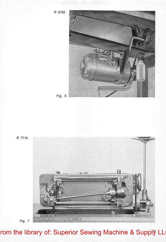
The oil seeps through a vent hole into the hollow arm shaft and is distributed inside the armshaft by a packing. Emerging from additional vent holes, oil is supplied to the variousarm shaft bearings and the feed eccentric. Dripping oil is collected by a large oil drippan and accumulates in a detachable plastic oil bottle. (Fig. 6)
R 7715
Fig. 3
From the library of: Superior Sewing Machine & Supply LLC

From the library of: Superior Sewing Machine & Supply LLC
From the library of: Superior Sewing Machine & Supply LLC

The oil which has accumulated in this bottle may be returned to the oil reservoir withoutprior cleaning. After the oil has circulated in the machine several times, it Is advisableto filter it through a piece of linen before it is returned to the reservoir. This will notImpair its lubricity in the least. Used oil, naturally, may be employed for other lubrication
purposes as well.
All other oiling points which are marked by arrows in Figs. 3, 4, 5, 7 and 8 have to be
oiled by hand.
Special care should be taken in applying oil to the large oiling felt which supplies oilto the needle vibrating eccentric and can be reached through aperture F (Fig. 5). Thispad should be soaked with oil regularly.
Put one drop of oil into the hook raceway each day the machine is in operation. Frequently take off the needle plate and remove the lint which has accumulated on its
underside and on the feed dog. This is very Important because the lint contains smallparticles of dressing which have an abrasive effect on the sewing hook and, in time,will cause excessive wear.
R 7722
Fig. 8
10From the library of: Superior Sewing Machine & Supply LLC

4. Test-Running the Machine
Before you test-run the machine, carefully remove the rust preventative.
After the machine has been lubricated as instructed above, test-run the unthread machine with a piece of fabric under the presser foot.
Before you plug the machine In, make sure that the voltage indicated on the rating plateof the motor is within the tension range marked on the electric meter.
Also, make sure the machine pulley rotates in the proper direction, i. e. toward you. Ifit does not, simply exchange the two wires at the motor terminals.
R 7685
Fig. 9
11From the library of: Superior Sewing Machine & Supply LLC

5. Removing the Bobbin Case
Raise the take-up lever to its highest position. Reach under the table with your left hand,open the bobbin case latch and pull out the bobbin case by holding this latch with thumb
and forefinger, as shown in Fig. 9.
While you hold the bobbin case by its open latch, the bobbin cannot fall out (Fig. 10).
R 7432
Fig. 10
From the library of: Superior Sewing Machine & Supply LLC

6. Winding the Bobbin
The Pfaff 238 is equipped with a bobbin winder which is mounted on the power table(Fig. 11).
This bobbin winder requires no lubrication since its spindle runs in a sintered-metalbushing.
The bobbin winder is stopped quietly by means of an adjustable leather pad.
Mount the bobbin winder on the table so that its pulley will not contact the driving beltwhen the winder is disengaged.
Place an empty bobbin on bobbin winder spindle 5. Lead the thread from the spool onpin 1 through thread guide 2 and clockwise around and between tension discs 3. Wind
a few turns of thread on the bobbin in clockwise direction.
Start the bobbin winder by depressing engaging lever 6. The bobbin winder will stopautomatically when the bobbin is full. The amount of thread to be wound on the bobbinis regulated by turning screw 7. Turn this screw clockwise for more thread, or counterclockwise for less thread.
If the thread should pile up at one end of the bobbin, loosen screw 4 and adjust thetension bracket, as appropriate.
R 6767
m
». IT
Fig. 11^^7
From the library of: Superior Sewing Machine & Supply LLC

7. Threading the Bobbin Case
Insert a full bobbin into the bobbin case so that the thread draws on the top from theleft toward the right (Fig. 12).
Hoid the bobbin firmly in the bobbin case, puli the thread into slot 1 and draw it under
the tension spring and into delivery eye 2. Turn the bobbin case so that the end of itsiatch points toward the right and place it on the center stud in the bobbin case base.Press against the bobbin case until you hear it snap into place.
Failure to observe this precaution may result in bobbin case or needle breakage.
R 4345
Fig. 12
14From the library of: Superior Sewing Machine & Supply LLC

8. Threading the Needle
Threading the Pfaff 238 Is simple because the thread passes down on the front ofthe machine in the operator's field of vision.
As iiiustrated in Fig. 13, lead the thread from the spool on the thread unwinder up andthrough the thread guide at the top of the rod, then down to thread guide 1 on topof the machine arm, through both its holes, and through all three holes in thread retainer 2, clockwise around and between tension discs 3, through the loop of threadcheck spring 4, under slack thread regulator 5, up and from right to left through thehole of take-up lever 6, down and through thread retainer 7, and from front to backthrough needle eye 8.
R 7723
Fig. 13
From the library of: Superior Sewing Machine & Supply LLC
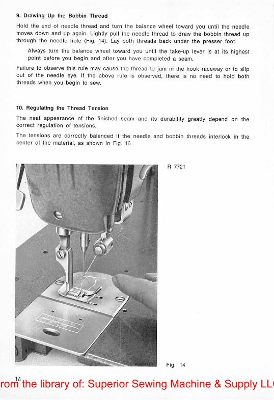
9. Drawing Up the Bobbin Thread
Hold the end of needle thread and turn the balance wheel toward you until the needlemoves down and up again. Lightly pull the needle thread to draw the bobbin thread upthrough the needle hole (Fig. 14). Lay both threads back under the presser foot.
Always turn the balance wheel toward you until the take-up lever is at its highestpoint before you begin and after you have completed a seam.
Failure to observe this rule may cause the thread to jam In the hook raceway or to slipout of the needle eye. If the above rule is observed, there is no need to hold boththreads when you begin to sew.
10. Regulating the Thread Tension
The neat appearance of the finished seam and its durability greatly depend on thecorrect regulation of tensions.
The tensions are correctly balanced if the needle and bobbin threads interlock in thecenter of the material, as shown in Fig. 16.
Fig. 14
From the library of: Superior Sewing Machine & Supply LLC

The needle thread tension is increased by turning tension nut Mclockwise, and decreased, by turning it counter-clockwise (Fig. 13).
The bobbin thread tension is regulated by means of the small hook screwdriver. Turntension screw z in for more tension, or out, for less tension (Fig. 15).
The tensions should be regulated according to the material to be sewn. Check to seethat the stitches are tightly drawn in without puckering the material, in straight sewing,the stitches should lie in a straight line, and in zigzag sewing, should form a perfectzigzag pattern on the lop and bottom of the material without kinking.
Fig. 15
The grade of thread used plays an important part in obtaining a perfect seam on anymaterial. Sheer fabrics require a thin and soft thread, whereas stiff and resistant threads,because of their low resilience, are unsuitable for almost any fabric.
You will have to have a little experience in order to be able to tell which tension needsadjustment.
Fig. 16
Fig. 17
Fig. 18
From the library of: Superior Sewing Machine & Supply LLC

In Fig. 17 either the upper tension is too tignt, or the lower tension too weak.
In Fig. 18 either the upper tension is too weak, or the lower tension too tight.
You will have to decide in every individual case, if either the upper or the lower tensionneeds to be adjusted, particulary when the thread forms small knots or kinks on top orbottom of the fabric.
Always lower the presser bar before you adjust the upper tension. When the presser baris raised, it will automatically release the tension.
11. Regulating the Stitch Length
The stitch length is regulated by turning thumb nut S on the feed regulator lever (Fig.19). This applies to both straight and zigzag sewing.
Turn this thumb nut right for shorter stitches, or left, for longer stitches.
The numerals on the left of the slot indicate the stitch length in millimeters.
The feed regulator lever is permanently held down in forward feeding position by springaction.
When you push the feed regulator lever up beyond the zero mark, the machine will feedin reverse. The lever will return to its forward feeding position automatically, when re
leased (Fig. 19). This feature is particularly useful for backtacking.
•mi R 7720
Fig. 19
From the library of: Superior Sewing Machine & Supply LLC

12. Regulating the Stitch Width
The stitch width is regulated by turning knob G which is located in the middie of the
machine arm (Fig. 20). The numerals on the zigzag scale indicate the stitch width inmillimeters.
When pointer Z is set on zero, the machine sews straight.
When you turn knob G to the left, the stitch width increases gradually and the machinemakes the zigzag stitch.
With the zigzag knob at the extreme left of its scale, the machine will make stitches
about 3/16" or V4" (4.5 or 6.0 mm) wide, depending on the machine model.
There is a small lug on the underside of pointer Z which engages in a notch of slide S.Screw B serves to lock this slide in position.
If you set the zigzag knob on 2 and tighten screw B, for instance, the stitch width is
fixed and will not be disturbed by the vibrations of the machine when sewing. In spite ofthis, knob G can be jerked to zero when a few straight stitches have to be made in back-tacking the end of a seam. By the same token, knob G can be jerked to the left for awider zigzag stitch. Returned to the middle of the zigzag scale, pointer Z will again engage in notch R of slide S so that the previous stitch width setting will be restoredautomatically.
Switching from straight to zigzag stitching as well as changing the stitch length and thestitch width can be done while sewing.
R 7719
Fig. 20
From the library of: Superior Sewing Machine & Supply LLC

13. Setting the Needle Position
Lever H can be set in notch I, II or III and serves to move the needle from the center
to the left or right of the needle plate slot.
With lever H In notch I, the needle is at the extreme left of the needle plate slot instraight sewing, and swings to the right in zigzag stitching.
When lever H is set in notch II, the needle is centered in the needle plate slot in straightsewing, and swings both ways in zigzag stitching.
With lever H in notch III, the needle is at the extreme right of the needle plate slot instraight sewing, and swings to the left in zigzag stitching.
The needle position can be changed while sewing. When the machine is not in operation, however, raise the needle out of the fabric before you change the needle position.Failure to observe this precaution may cause bending or breaking of the needle.
14. Regulating the Pressure on the Material
Smooth feeding and uniform stitching greatly depend on the correct amount of presserfoot pressure. Staggering stitches and feed markings on the underside of the fabric area direct result of incorrect pressure regulation.
To increase the pressure for heavier fabrics, turn screw V in, and to ease the pressurefor lightweight materials, turn it out (Fig. 13).
When stitching delicate and sheer fabrics, feed a piece of tissue paper under the material to protect it from the feed points and prevent puckering. This paper can be readiiypulled away after sewing has been completed.
15. Selecting the Correct Needle
The Pfaff 238 is fitted with round-shank needles.
Model A machines use short System 133 needles which will not tremble, regardless of thesewing speed, and hence assure neat seams.
Model B machines are equipped with System 134 R needles which are about 5/32", or4 mm, longer and are available in a number of different point styles to suit variousmaterials.
Pfaff 238-115 cording machines use System 130 B needles with a smaller shank diameter. Pin tucks are made with two System 130 Br and Bl needles which are placed between the needle holder jaws with their flat sides facing, and are secured in position bytightening the needie gauge regulating screw. To make three System 134 RFr RFI needleshaving a flat on the right and left side of the shank, respectively, and two System 134Rfmc needles whose shank is flattened on both sides.
The number indicating the needle size is identical with the diameter of the needle shaft,or blade, expressed in hundredths of millimeters. Thus, if the diameter of a needle is0.8 mm, its size Is 80.
20From the library of: Superior Sewing Machine & Supply LLC

The appearance of the finished seam Is dependent on the correct relationship betweenneedle, thread and fabric.
Lightweight fabrics should be sewn with a thin needle in order to prevent ugly needlemarks.
When thick thread is used in a thin needle, the thread is likely to break. Thin threadused in a thick needle may cause skipping of stitches.
Select the proper needle and thread sizes from the chart below:
Never use rusty needles.
Only the exceptional quality of the needle finish ensures trouble-free sewing and prevents thread breaking. When operating at the high speed of the Pfaff 238, a rough-surfaced needle will overheat quickly and burn the thread. This is particularly true ofsynthetic threads which are very sensitive to heat and fuse easily.
If an ordinary needle should overheat when sewing resistant materials or stitching longseams, we recommend that you use a superfinished, chromium-plated System 134 needlewhich may be obtained from us.
Needle and Thread Chart
Needle Size Cotton Silk Synthetic Linen
60130/3
130/4140/3 200/3-150/3
70100/3
100/4120/3 140/3-120/3
8080/3
80/4100/3 120/3-100/3
9070/3-60/3
70/4-60/480/3 100/3- 80/3 70/3
10050/3-40/3
50/4-40/4
30/3
70/3 70/3 60/3
110 30/4
30/6
60/3 60/3 50/3
21From the library of: Superior Sewing Machine & Supply LLC

16. Changing the Needle
(1) Raise the needle bar to Its highest point.
(2) Loosen the needle set screw, using a small screwdriver for this purpose.
(3) Pull out the old needle.
(4) Insert a new needle Into the opening of the needle clamp and push it up as far asit will go. Make sure the long groove faces toward you.
(5) Tighten the needle set screw securely.
17. The Sewing Hook
The Pfaff 238 is organized with a System 134 double-revolution, transverse rotary hookwhich moves counter-clockwise and is equipped with a special balancing collar toensure vibrationless running of the machine.
This sewing hook features a welcome improvement over the old-type hook In that itsgib is held In place by one screw instead of the three screws used previously. Thisscrew (e in Fig. 21) is located at one end of the hook gib while its other end enters asmall recess in the body of the hook. Removal of the gib for a thorough cleaning ofthe hook, or in case of thread jamming, is exceedingly simple. Since the hook gib issecured by one screw and the hook thread guard, or thread pull-off flange, by three,the two parts cannot possibly be confused.
The springiness of the redesigned gib prevents bobbin case breakage as a result ofthread jamming. Furthermore, the machine will never be blocked to an extent which willmake it impossible to get at the gib screw. All this will eliminate the necessity of removing the hook, resetting the hook shaft and retiming the sewing hook, a job for whicha mechanic normally has to be called.
Fig. 21
From the library of: Superior Sewing Machine & Supply LLC

18. Pfaff 238-14 for Eyeletting
The Pfaff 238-14 eyeletting machine is supplied in two varieties. Whiie on the Pfaff238-14/1 the work is turned about the center stud by hand, the Pfaff 238-14/2 isequipped with positive rotary feed.
Operation of the Pfaff 238-14/1 is exceedingly simple.
Put needle position lever H in notch III (Fig. 20) so that the needle swings from right toleft in zigzag sewing.
Select a slide with a stud diameter which suits the size of the eyelets you want tomake. Push this slide into the siot of the needle plate and position it so that the needlewill be just inside the groove in the center stud when it descends on the right of its throw.
Punch out the hole for the eyelet, using one of the punches suppiied with the machine.Make sure the punch diameter is smailer than the center stud diameter so that the material will fit around the stud snugly. Slip the fabric over the center stud and push itdown evenly all around.
Select the stitch width according to the thickness of the material and the type of eyeletdesired. To sew a neat eyelet, run the machine at a uniform speed while turning thework around the center stud evenly.
Another procedure which may be applied is as follows:
Put needle position lever H in notch I and turn knob G to the desired stitch width. Rotate the balance wheel until the needle descends on the left of its throw. Position the
slide so that there is a small clearance between the needle and the center stud. The
slide must be repositioned whenever the stitch width is changed.
This setting affords the advantage that the stitch width can be changed several times inthe process. Thus, it is possible to join multiple plies by sewing around the hole withstraight stitches (before sewing the eyelet seam with zigzag stitches) and to finish theeyelet with a few tying stitches (with knob G set on "O").
To prepare the machine for eyeletting, exchange the ordinary needle plate and thepress-er foot for the special needle plate and eyeletting foot.
The set of organizational parts for subclass -14/1 machines consists of the following:
1 Eyeletting foot No. 41500
1 Needle plate No. 42362
1 Eyeletting slide, w/4 mm -dia. stud. No. 42359
1 Eyeletting slide, w/5 mm -dia. stud. No. 42380
1 Eyeletting slide, w/6 mm -dia. stud. No. 42361
1 Clamping screw No. 799
1 Punch, 3 mm -dia., No. 41664
1 Punch, 4 mm -dia.. No. 41665
1 Punch block No. 32424710
23From the library of: Superior Sewing Machine & Supply LLC

42359 42360
32424710
The following parts will be supplied on special request:1 Eyeletling slide, w/3 mm -dia. stud, No. 423581 Eyelelting slide, w/7 mm -dia, stud, No. 461591 Eyeletting slide, w/8 mm -dia. stud. No. 461621 Punch, 2 mm dia., No. 41663
2 mm = 5/64"; 3 mm = 1/8"; 4 mm = 5/32";5 mm = 3/16": 6 mm = 1/4"; 7 mm = 9/32";8 mm = 5/16".
ii
42361 799
From the library of: Superior Sewing Machine & Supply LLC

Operation of the Pfaff238-14/2 is basically the same as of the Pfaff 238-14/1, except thatthe material is turned about the center stud by a positively driven rotary feed ratherthan by hand.
The Pfaff 238-14/2 is available in two varieties:
Group I for center studs of from 5/64" to 15/32" {2-10 mm) dia.
Group II for center studs of from 7/16" to 23/32" (11-18 mm) dIa.
Ail that is required to change the size of the eyelet within one of the above groups isto exchange the slide with center stud and the presser ring disc In the eyeletting foot.When changing over from group I to group II, or vice versa, the rotary feed has to beexchanged in addition. This conversion job can be performed by every mechanic in afew minutes.
The mechanical setup of the rotary-feed eyeletting unit is illustrated in Fig. 22.
Fig. 22
From the library of: Superior Sewing Machine & Supply LLC

19. Pfaff 238-115 for Cording
The Pfaff 238-115 is specially fitted for multi-needle decorative stitching and cordingoperations. To suit different requirements, this machine is supplied in a number ofvarieties equipped with different needle holders, cording plates and cording feet, asfollows:
238-115/1-6 Two and three-needle ornamental stitching in straight or narrow zigzagstitch; needle plate slot 3/16" or 1/4" (4.5 or 6.0 mm) wide; needle holder fitted with double-threaded screw; System 130 B needles.
238-115/1-45 Two or three-needle air cording; needle holder fitted with double-threaded screw; System 130 Br and 130 Bl needles.
The needle gauge can be adjusted by turning only one screw. Availablefor maximum needle gauges of 1/8", 3/16", and 1/4" (3.0, 4.5 and6.0 mm).
238-115/1-235 Same as 238-115/1-45, but fitted to make filled cording: System 130 Brand 130 Bl needles.
238-115/2-45 Two-needle air cording in needle gauges ranging from 1/16" to 1/4"(1.4 —6.0 mm); needle holder jaws individually adjustable; available formaximum needle gauges of 1/8", 3/16", and 1/4" (3.0, 4.5 and 6.0 mm);System 134 R needles.
238-115/2-245 Same as 238-115/2-45, but fitted to make filled cording; System 134 Rneedles.
238-115/4-45 Four-needle air cording on gloves, etc.; needle holder fitted with double-threaded screw; four needles are inserted in slot of needle holder jawsand are clamped in position by tightening double-threaded screw; shanksof outer needles are flattened on one side, while shanks of inner needles are flattened on both sides; over-all width of triple cording 3/16" or7/32" (4.7 or 5.4 mm); System 134 Rfr and 134 RFI or System 134 Rfmcand 134 Rfmh needles.
238-115/5 This variety is supplied on special request only. Fitted with exchange-abie needle holders for 1, 2 and 3 needles; can be combined with subclass -6, -45 and -245 organizations; System 130 B or 130 Br and 130 Blneedles.
26From the library of: Superior Sewing Machine & Supply LLC

Listed on the opposite page are a variety of feed dogs, needle piates, needle piate inserts and cording feet which may be used on Pfaff 238-115 machines. One needle piate,four needle plate inserts and four cording feet are standard with each machine.
Since the composition of the individual parts sets depends on the thickness of the material to be sewn, no hard-and-fast rule can be given as to which parts are required fora certain cording size.
Fig. 23 shows the Pfaff 238-115/1-245 fitted with needle plate insert and adjustable needleholder for filled cording work.
Apart from cording work, the Pfaff 238-115 can also be used for sewing ornamentai two-needle zigzag seams. For this type of work, it is set for a narrow zigzag stitch and anarrow needle gauge, if the machine is to be used for single-needle zigzag stitching,simply insert one needle between the needle holder jaws.
R 6365
Fig. 23
From the library of: Superior Sewing Machine & Supply LLC

Organizational Parts for the Pfaff 238-115
Needle plate, for 1/8", of 3.0 mm, needle gauge
Feed dog, for 1/8", or 3.0 mm, needle gauge
Needle plate, for 3/16", or 4.5 mm, needle gauge
Feed dog, for 3/16", or 4.5 mm, needle gauge
Needle plate, for 1/4", or 6.0 mm, needle gauge
Feed dog, for 1/4", or 6.0 mm, needle gauge
Cording slide, w/o ridge
Cording slides, w/ ridges from 1/32" to 9/64", or0.8 to 3.6 mm high, in steps of 0.2 mm
Cording slides, w/ cord ducts from 1/32" to 3/32"or 0.6 to 2.4 mm, dia., in steps of 0.2 mm
Cording slide set screw
Cording foot, w/ 11 grooves, 0.6 x 0.8 mm,for 1/8", or 3.0 mm, needle gauge
Cording foot, w/ 11 grooves, 0.8 xl.O mm,for 1/8", or 3.0 mm, needle gauge
Cording foot, w/ 9 grooves, 1.0 x 1.2 mm, for
1/8", or 3.0 mm, needle gauge
Cording foot, w/ 9 grooves, 1.2 x 1.4 mm,for 3/16", or 4.5 mm, needle gauge
Cording foot, w/ 7 grooves, 1.6 x 1.6 mm, for3/16", or 4.5 mm, needle gauge
Cording foot, w/ 7 grooves, 2.0 x 1.8 mm, for3/16", or 4.5 mm, needle gauge
Cording foot, w/ 5 grooves, 2.4 x 2.0 mm, for3/16", or 4.5 mm, needle gauge
Cording foot, w/ 5 grooves, 2.8 x 2.4 mm,for 3/16", or 4.5 mm, needle gauge
Cording foot, w/ 3 grooves, 3.4 x 2.8 mm, for 1/4"or 6.0 mm, needle gauge
Cording foot, w/ 3 grooves, 4.5 x 3.2 mm, for1/4", or 6.0 mm, needle gauge
28
No. 26835
No. 26833
No. 26885
No. 26883
No. 26892
No. 26890
No. 26902
No. 26900 X
height of ridge
No. 26904 X
cord duct dia.
No. 564
No. 51263
No. 51265
No. 51267
No. 51269
No. 51271
No. 51273
No. 51275
No. 51277
No. 51279
No. 51281
From the library of: Superior Sewing Machine & Supply LLC

•AH
tm
iiit
nii
tnii
tii
S>.
From the library of: Superior Sewing Machine & Supply LLC

From the library of: Superior Sewing Machine & Supply LLC

20. Pfaff 238-130 with Knee-Operated Stitch Width Control
This machine features a knee-operated stitch width control which greatly facilitates suchoperations as single-needle cording, eyelet embroidery and flat embroidery in the production of white goods, blouses, etc. (Fig. 24). A second treadle serves to raise thepresser foot.
When knee pressure is relieved, the stitch width control is automatically returned to"0" by spring action.
On the Pfaff 238-130 the lug on the underside of pointer 2 fits snugly into notch R ofslide S (Fig. 20). For this reason, screw B must be loosened when the stitch width is tobe varied by knee action while sewing.
Screw B is tightened to lock the slide for any desired stitch width so that the operatorneed not press against the knee lever continuously when sewing satin-stitch seamswith a uniform stitch width throughout, in this way, the Pfaff 238-130 can be used forordinary zigzag sewing, To this end, an ordinary zigzag foot with a smooth sole isattached to the presser bar.
R 7213
Fig. 24
31From the library of: Superior Sewing Machine & Supply LLC

Satin-stitch seams are made with hinged zigzag foot No. 51355 which has a relieved
sole and permits to sew bends without compressing the seam.
If a more prominent seam is to be produced, we recommend to use sewing foot No.51353 which has three cord ducts in front of the needle hole.
Interesting effects can be obtained by varying the needle position, 1. e. by putting leverH in notch I, il or Mi, so that the needle swings to the right, to the left, or both ways
from the middle.
From the library of: Superior Sewing Machine & Supply LLC

From the library of: Superior Sewing Machine & Supply LLC

21. Trouble Shooting
Machine Skips Stitches
Cause:
1. incorrect threading.
2. Wrong needle.
3. Needle inserted incorrectly.
4. Needle too fine for the thread used.
5. Needle too thick for the thread used.
6. Needle bent.
7. Needle set too high or too low.
8. Hook set too far from needle (correct clearance .004", or 0.1 mm).
9. Hook timed Incorrectly.
10. Material tacky or heavily dressed.
11. Thread twisted too much.
Thread Breaks
Cause:
1. Any of the above-mentioned conditions may cause thread breakage.
2. Thread tension too tight.
3. Poor or knotty thread used.
4. Thread rotten due to extremely long and dry storage.
5. Poor-quality thread used.
6. Thread jammed In hook race.
7. Burrs or sharp edges on needle plate slot.
8. Thread snarled up on spool pin.
9. Thread check spring timed Incorrectly.
10. Blunt needle point.
Needle Breaks
Cause:
1. Bent needle strikes hook point.
2. Thread too heavy for needle used.
3. Hook setting disturbed after thread jamming.
4. Upper tension too tight.
5. Needle deflected by hard spots In material.
6. Needle bent because material Is pushed or pulled.
7. Machine feeds while needle Is down in material.
8. Hook set too close to needle.
9. Needle too fine for the fabric.
10. Thread snarled up on spool pin.
34From the library of: Superior Sewing Machine & Supply LLC

Machine Feeds improperly
Cause:
1. Feed dog set too low.
2. Feed teeth too fine for the material.
3. Feed dog unsuitable for the work to be performed.
4. Incorrect pressure on material.
5. Accumulations of packed lint between feed teeth.
6. Blunt feed points.
Overheating
Cause:
1. No oil In reservoir.
2. V-belt too tight, causing excessive pressure on arm shaft bearings.
3. Full weight of motor pulls down V-belt because belt take-up hanger has come loose.
35From the library of: Superior Sewing Machine & Supply LLC

Pfaff 238-0 High-Speed Zigzag Sewing Machine
22. Brief Description of the Pfaff 238-0
With the introduction of its 01. 238-0, Pfaff has met the demand of the sewing industryfor a more efficient high-speed sewing machine. The mechanical setup of the Pfaff 238-0closely resembles that of the job-proven Pfaff 238, while its sewing speed has beenincreased from 3,800 to 4,500 s.p.m. through the incorporation of the following improvements:
fvlaintenance-free anti-friction bearings instead of plain bearings at both ends of the armshaft, sealed-for-life needle bearings in the take-up lever assembly, wick-lubricatedneedle bar bushings, and a separate wick and reservoir lubrication system for thesewing hook.
With the exception of Chapter 3, entitled "The Lubrication System", all instructions given for Pfaff 238 apply to the Pfaff 238-0 also.
R 9401
f"i9- 26
From the library of: Superior Sewing Machine & Supply LLC

23. The Lubrication System of the Pfaff 238-0
From the oil reservoir under the top cover of the machine oii is supplied not only tothe arm shaft center bearing and the zigzag mechanism in the machine arm, but also tothe two needle bar bushings in the needle bar frame. For this purpose, a wick-fiiied piastictube has been incorporated which conducts oii from the oii reservoir to both needlebar bushings.
From time to time, check the oii level in the oii sight glass and replenish the oil, ifnecessary.
The high speed of the machine has made it necessary to incorporate a combinationwick and reservoir lubrication system for the transverse rotary hook.
The sewing hook is lubricated from the oii reservoir under the bed plate (Fig. 26). Awick-fiiied piastic tube conducts oii to the hook saddle whence it flows through a coppertube into the oii retainer ring on the sewing hook. Centrifugal force then flings theoii through an oii duct into the hook raceway.
This reservoir lubrication system minimizes maintenance and ensures that all vital partsare properly lubricated at all times.
The bed plate reservoir holds 5 1/3 fl. oz. of oil which will last for several weeks' lubrication. The oii level can be checked through an oil sight glass on the bottom of thereservoir and the oil be replenished. If necessary. Checking the oil level may be combined with the weekly cleaning of the machine. To top up the oil, you do not lose thegasket.
The Pfaff 238-0 uses the same oii as the Pfaff 238, i. e. either ordinary sewing machineoil No. 2801-120122 or a technical white oil having a viscosity of 150R/68®F or 175 S/68°F.
The oiling points which have to be lubricated manually are marked by arrows in theillustrations on pp. 4-8.
37From the library of: Superior Sewing Machine & Supply LLC

Instructions for Mechanics
24. Timing the Thread Check Spring
The functions of the thread check spring are to assist the take-up lever in taking upthe balance of the needle thread after the loop has passed around the bobbin, In setting the stitch to the desired tightness, and in controlling the slack of the needle threadfrom the time the descending take-up lever begins to draw the thread from the spooluntil the needle reaches the goods.
R 7880
IjTj irf J
Fig. 27
From the library of: Superior Sewing Machine & Supply LLC

The downward stroke of the thread check spring is limited by a stop on the tensionbarrel and can be adjusted by rotating this barrel, as may be required.
To do this, insert a screwdriver into opening E (Fig. 27), loosen the tension barrel setscrew and, inserting the screwdriver into the slot of tension stud M, turn the latter untilthe tension barrel is in the correct position.
To adjust the thread check spring tension, turn tension stud M in the tension barrel.If it should be impossible to turn the tension stud in the tension barrel with the aid of ascrewdriver, loosen the tension barrel set screw in opening E (Fig 27), take the tensionbarrel out of the machine and slightly loosen the set screw at its rear end. After thetension barrel has been replaced in the machine, the stroke of the thread check springmust be readjusted.
R 7887
Fig. 28
39From the library of: Superior Sewing Machine & Supply LLC

Thread regulator J (Fig. 28) Is mounted on the presser bar guide collar and moves upand down with the presser bar as the sewing foot passes over Irregularities In thickness.By so doing, It adapts the thread consumption to the varying thicknesses of the material being sewn. As a result of this action, the check spring has to take up less threadwhen thicker portions of the material pass under the sewing foot.
Thread regulator J can be adjusted vertically after loosening screw d (Fig. 28). Bysetting the thread regulator higher or lower the amount of thread to be controlled bythe thread check spring can be adjusted within certain limits. It Is recommended tocorrelate the thread regulator and tension barrel settings so that the thread checkspring not only takes up the proper amount of thread, but also pulls the thread upwards perpendicularly.
Once you are familiar with the functions performed by both the check spring and thethread regulator, you will be able to make the proper adjustment right away withoutresorting to trial-and-error methods.
The thread check spring is timed correctly If it Is through acting when the needle reaches the goods. Since the take-up lever of the Pfaff 238 makes a rather long stroke, itmay be necessary to Increase the stroke of the thread check spring somewhat so thatit will still exert a slight pull on the thread when the needle enters the material.
25. Timing the Sewing Hook
To time the sewing hook correctly, we recommend that you use a needle rise gaugewhich can be obtained from us under Order Nos. 880136/01 and 880137/00.
Begin by removing the needle plate and setting lever H In notch II and knob G on "0"(Fig. 20). Rotate the balance wheel until the needle has reached the lowest point of Itsstroke. Slip both the needle rise gauge (5/64", or 2.0 mm, thick and the clamp onto theneedle bar, push the clamp up against the gauge until the latter contacts the needlebar frame, and tighten the clamp screw securely (Fig. 29).
Then pull out the gauge and cautiously turn the balance wheel until the clamp contactsthe needle bar frame (Fig. 30). Loosen set screws K and T (Figs. 29 and 30, respectively)and rotate the sewing hook on Its shaft until Its point Is opposite the center line of theneedle.
At the same time, set the hook as close to the needle as possible, the proper clearancebetween both parts being .004", or 0.1 mm (Fig. 31).
40From the library of: Superior Sewing Machine & Supply LLC

From the library of: Superior Sewing Machine & Supply LLC

26. Setting the Needle Bar at Correct Height
To set the needle bar at the correct height, turn knob G (Fig. 20) to "4" and rotatethe balance wheel until the hook point is opposite the center line of the needle whenthe latter ascends on the left of its throw. When in this position, the hook point shouldbe positioned .04", or 1.0 mm, above the top of the needle eye {Fig. 31a).
If adjustment is required, loosen set screw m (Fig. 28) and set the needle bar higher orlower, as may be required.
R 7881
Wmm
Fig. 31a
Fig. 31
42From the library of: Superior Sewing Machine & Supply LLC

27. Changing the Sewing Hook
1. Remove needle, needle plate, feed dog and bobbin case position finger bracket.
2. Loosen hook set screws K and T (Figs. 29 and 30).
3. Rotate the balance wheel until the feed bar is at its highest point.
4. Pull the sewing hook off Its shaft.
5. With the feed dog set at Its highest point, push the new hook onto the hook shaft andreplace the bobbin case position finger bracket. As you replace this bracket, makesure there is a clearance of .024 to .036", or 0.6 to 0.9 mm, between the tip of theposition finger and the bottom of the position slot in the bobbin case base (Fig. 31).
6. Time the sewing hook as instructed in Chapter 25 and tighten set screws K and Tsecurely.
7. Replace feed dog and needle plate.
28. Dismantling the Thread Take-up
1. Remove face cover, presser foot (with screw) and needle.
2. Take out pressure regulating screw and remove presser bar spring. Loosen set screwc (Fig. 28) and pull the presser bar up out of the machine.
Pull thread regulator J (Fig. 28), presser bar guide collar and presser bar liftingbracket back out of the machine.
3. Remove complete needle bar frame assembly so that the height setting of the needlebar will not be disturbed. To do this, loosen set screw b (Fig. 36) and removeeccentric stud a. Then loosen screw f (Fig. 28) and pull out hinge stud g. This done,
pull the needle bar frame, enclosing the needle bar, forward out of the machine.
4. Take out plastic plug U on the back of the machine arm (Fig. 32) and strip the lift
ing lever assembly.
5. Rotate the balance wheel until take-up crank screw Q in the needle bar crank can
be reached through the aperture on the back of the machine arm (Fig. 33).
6. Loosen take-up crank screw Q.
7. Loosen set screw P on take-up link stud (Fig. 33).
8. Place the bar of the pull-off device across the face side of the machine, as shown in
Fig. 34. Insert the threaded end of the pull-off device through the hole in the bar, screw
it into the hollow hinge stud of the take-up link and, in this way, pull the hinge studout of its mount. (The pull-off device is available under No. 880141/00 and will besupplied at extra cost.)
9. Cautiously pull out the take-up lever assembly, including the take-up lever link, take-
up crank and needle bar connecting link.
43From the library of: Superior Sewing Machine & Supply LLC

r 4
m
From the library of: Superior Sewing Machine & Supply LLC

Do not apply force in removing the take-up lever assembly since all parts are precision-engineered and meticulously fitted. Do not tap these parts out of their mount as thisv/ould upset the position of the press-fitted bearing rings.
The boreholes at the lower end of the take-up lever and the upper end of the needlebar connecting link are fitted with super-finished needle bearings.
Note that end screw L (Fig. 34) must be turned right to loosen it because It has left-hand thread.
In stripping the thread take-up and needle bar assemblies care should be taken thatnone of the 18 tiny needles gets lost which are contained In each bearing. To facilitateinsertion of the needles into the bearings, put some grease into the latter and insertthe needles singly, using a pair of tweezers.
To replace the thread take-up and needle bar assemblies, reverse the above procedureand proceed with great care.
R 7882
Fig. 34
From the library of: Superior Sewing Machine & Supply LLC

29. Adjusting the Stitdi Length for Forward and Reverse Sewing
Pfaff 238 machines normally are set to make stitches of exactly the same length, regard
less whether they sew forward or backward. This feature will be much appreciated because the needle, In backtacking the end of a seam, will stitch into the same holeswhich were made in forward sewing.
To change the relative stitch lengths in forward and backward sewing, loosen clampingscrew N In the feed regulator slot (Fig. 35), hold feed regulator lever A steady and ad
just the length of forward stitches by turning crank 0 on Its shaft, as appropriate. Turncrank O upwards for longer stitches, or downwards, for shorter stitches.
In this way, the stitch length relationship of forward and backward stitches can be regulated, as desired. After the adjustment, tighten clamping screw N securely.
R 5092
Fig. 35
From the library of: Superior Sewing Machine & Supply LLC

30. Centering the Needle Throw In the Needle Plate Slot
When the machine Is set for Its widest zigzag stitch, the needle should be centeredcorrectly In the needle plate slot and. descending on the right and left of Its throw,should clear both ends of the slot at the same distance. If adjustment is required, loosenpinch screw b (Fig. 36) and turn eccentric stud a in the needle bar frame pitman tothe right or left, as may be required.
R 7884
f
Fig. 361
47From the library of: Superior Sewing Machine & Supply LLC

31. Zeroing the Needle for Straight Stitching
When knob G (Fig. 20) is set on "0", the needle bar must not make any sidewaysmotion and the machine should sew a perfectly straight seam. To check this setting,drop the feed dog, place a piece of thin cardboard under the sewing foot and turn
knob G to "0". Rotate the balance wheel forward, then backward, and let the needle
stitch into the cardboard lightly. The needle is zeroed correctly, if both punctures areexactly In the same spot.
If adjustment is required, slightly loosen the set screw on knob G (Fig. 20), hold theknob steady and turn the zigzag regulator stud to the right or left, as appropriate. Make
sure the zigzag regulator stud has no end play and tighten the set screw securely.
R 7883
Fig. 37
From the library of: Superior Sewing Machine & Supply LLC

32. Adjusting the Needle Position
Pfaff 238 machines normally are set to make zigzag stitches which extend the samedistance from the zero position both ways (central needle position). To check this setting, set knob G on "0" and put lever H in notch II (Fig. 20). Place a piece of thin cardboard under the sewing fool and rotate the balance wheel toward you until the needlestitches into the cardboard lightly. Flick knob G to "4", rotate the balance wheel forward, then backward, and let the needle, descending on the right and left of its throw,stitch into the cardboard lightly. The setting is correct if the right and left punctures areequidistant from the central puncture.
To adjust, loosen set screw 1 (Fig. 37) and turn eccentric stud h to the right or left, asappropriate. Then tighten set screw i securely.
R 6686
Fig. 38
33. Adjusting the Needle Throw
The sideways motion of the needle bar must be timed correctly in relation to Its verticalmotion so that the needle will not begin to vibrate until it has risen clear of the goodsand will cease vibrating when it again reaches the goods.
To check this setting, flick knob G to "4" and watch the needle vibration. If adjustmentis required, rotate the bevel gear on the arm shaft, as may be required.
To double-check this setting, raise the needle bar to Its highest point and set lever H
(Fig. 20) In notch II. The setting is correct if the needle bar makes no sideways motionwhen you turn knob G to the right and left.
For a coarse adjustment, rotate the balance wheel until set screw Q on the needle barcrank (Fig. 33) is visible In the aperture in the machine arm. Loosen set screws k and
I (Fig. 38) and turn the arm shaft bevel gear until lobe w of the needle vibrating eccentric (Fig. 33) points upward. Tighten both set screws securely after the adjustment.
49From the library of: Superior Sewing Machine & Supply LLC

Contents
Page
Instructions for Operators
1. Brief Description of the Pfaff 238 5
2. Setting Up the Machine 5
3. The Lubrication System 7
4. Test-Running the Machine 11
5. Removing the Bobbin Case 12
6. Winding the Bobbin 13
7. Threading the Bobbin Case 14
8. Threading the Needle 15
9. Drawing Up the Bobbin Thread 16
10. Regulating the Thread Tension 16
11. Regulating the Stitch Length 18
12. Regulating the Stitch Width 19
13. Setting the Needle Position 20
14. Regulating the Pressure on the Material 20
15. Selecting the Correct Needle 20
16. Changing the Needle 22
17. The Sewing Hook 22
18. Pfaff 238-14 for Eyeletting 23
19. Pfaff 238-115 for Cording 26
20. Pfaff 238-130 with Knee-Operated Stitch Width Control 31
21. Trouble Shooting 34
Pfaff 238-0 High-Speed Zigzag Sewing Machine
22. Brief Description of the Pfaff 238-0 36
23. The Lubrication System of the Pfaff 238-0 37
Instructions for Mechanics
24. Timing the Thread Check Spring 38
25. Timing the Sewing Hook 40
26. Setting the Needle Bar at Correct Height 42
27. Changing the Sewing Hook 43
28. Dismantling the Thread Take-up 43
29. Adjusting the Stitch Length for Forward and Reverse Sewing .... 46
30. Centering the Needle Throw in the Needle Plate Slot 47
31. Zeroing the Needle for Straight Stitching 48
32. Adjusting the Needle Position 49
33. Adjusting the Needle Throw 49
51-From the library of: Superior Sewing Machine & Supply LLC

ST
(ptur f
No. 9497 engl. P 368 Printed In Germany
From the library of: Superior Sewing Machine & Supply LLC