petrol diesel level sensor

1
Petrol/Diesel Level Sensor Paul de Ruijter (The Netherlands) This sensor is particularly suitable for use in small spaces, such as the petrol tank of a motorbike. It has the advantage of not having any moving parts, unlike a conven- tional sensor with a float and float arm that make it difficult to fit in a tank. The sensor circuit is made from standard, inexpensive compo- nents and can be put together for little money. The operating principle is based on measuring the forward volt- ages of two identical diodes (check this first by measuring them). The forward voltage of a diode decreases with increasing junction temperature. If a resistor is placed close to one of the two diodes, it will be heated slightly if it extends above the sur- face of the petrol. For best results, the other diode (used for reference) should be located at the same level. If the diodes are covered by the petrol in the tank, the heating resis- tor will not have any effect because it will be cooled by the petrol. An opamp compares the voltage across the two diodes, with a slightly smaller current passing through the reference diode. When the petrol level drops, the out- put of the opamp goes high and the output transistor switches on. This causes a sense resistor to be connected in parallel with the sensor output. Several sensor circuits can be used together, each with its own switched tom so that splashing petrol does not cool the heater resistor, since this would result in false readings. The circuit should be powered from a regu- lated supply voltage of 5 to 6 V to prevent the heating resistors from becoming too hot. After testing everything to be sure that it works properly, it’s a good idea to coat the circuit board with epoxy glue to provide bet- ter protection against the petrol. Tip: you can use the well-known LM3914 to build a LED display with ten LEDs, which can serve as a level indicator. Several examples of suitable circuits can be found in back issues of Elektor. Note: this sensor circuit is not suitable for use in conductive liquids. (100335-I) sense resistor connected in parallel with the output, and the resulting output signal can be used to drive a meter or the like. Using this approach, the author built a petrol tank ‘sensor strip’ tank consisting of five PCBs, each fitted with two sensor circuits. With this sensor strip installed at an angle in the tank, a resolution of approximately 1.5 litre per sen- sor is possible. Many tanks have an electrical fitting near the bottom for connection to a lamp on the instrument panel that indicates the reserve level. The sensor strip can be used in its place. You will have to experiment a bit with the val- ues of the sense resistors, but do not use val- ues lower than around 100 Ω. It is also impor- tant to fit the diodes and heater resistor in a little tube with a small opening at the bot- 0V LEVEL R1 100k R2 120k R3 100R R5 * D1 1N4148 D2 C1 100n R4 22k T1 BC847 2 3 1 IC1.A 2x R6 100k R7 120k R8 100R R10 * D3 1N4148 D4 R9 22k T2 BC847 6 5 7 IC1.B 2x R * 100335 - 11 +6V 8 4 IC1 IC1 = LM358 SENSOR GND Personal Download for Gunawardena, Kapila | copyright Elektor

Upload: shamila-dilruckshi

Post on 20-Apr-2015

58 views

Category:

Documents


5 download

TRANSCRIPT

� 7/8-�010 elektor

Petrol/Diesel Level SensorPaul de Ruijter (The Netherlands)

This sensor is particularly suitable for use in small spaces, such as the petrol tank of a motorbike. It has the advantage of not having any moving parts, unlike a conven-tional sensor with a float and float arm that make it difficult to fit in a tank.The sensor circuit is made from standard, inexpensive compo-nents and can be put together for little money.

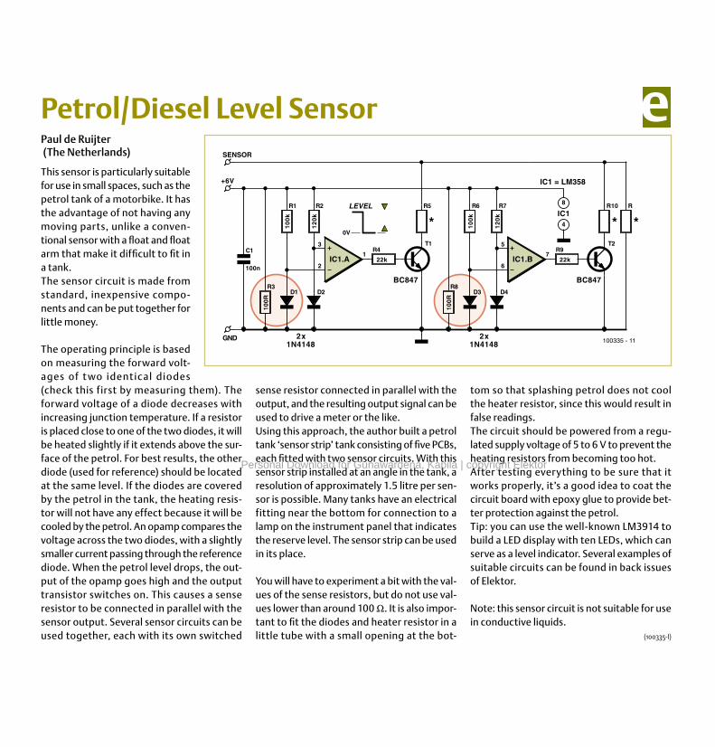
The operating principle is based on measuring the forward volt-ages of t wo identical diodes (check this first by measuring them). The forward voltage of a diode decreases with increasing junction temperature. If a resistor is placed close to one of the two diodes, it will be heated slightly if it extends above the sur-face of the petrol. For best results, the other diode (used for reference) should be located at the same level. If the diodes are covered by the petrol in the tank, the heating resis-tor will not have any effect because it will be cooled by the petrol. An opamp compares the voltage across the two diodes, with a slightly smaller current passing through the reference diode. When the petrol level drops, the out-put of the opamp goes high and the output transistor switches on. This causes a sense resistor to be connected in parallel with the sensor output. Several sensor circuits can be used together, each with its own switched

tom so that splashing petrol does not cool the heater resistor, since this would result in false readings.The circuit should be powered from a regu-lated supply voltage of 5 to 6 V to prevent the heating resistors from becoming too hot.After testing everything to be sure that it works properly, it’s a good idea to coat the circuit board with epoxy glue to provide bet-ter protection against the petrol.Tip: you can use the well-known LM3914 to build a LED display with ten LEDs, which can serve as a level indicator. Several examples of suitable circuits can be found in back issues of Elektor.

Note: this sensor circuit is not suitable for use in conductive liquids.

(100335-I)

sense resistor connected in parallel with the output, and the resulting output signal can be used to drive a meter or the like.Using this approach, the author built a petrol tank ‘sensor strip’ tank consisting of five PCBs, each fitted with two sensor circuits. With this sensor strip installed at an angle in the tank, a resolution of approximately 1.5 litre per sen-sor is possible. Many tanks have an electrical fitting near the bottom for connection to a lamp on the instrument panel that indicates the reserve level. The sensor strip can be used in its place.

You will have to experiment a bit with the val-ues of the sense resistors, but do not use val-ues lower than around 100 Ω. It is also impor-tant to fit the diodes and heater resistor in a little tube with a small opening at the bot-

0V

LEVELR1

10

0k

R2

12

0k

R3

100R

R5

*

D1

1N4148

D2

C1

100n

R4

22k

T1

BC847

2

3

1IC1.A

2x

R6

10

0k

R7

12

0k

R8

100R

R10

*

D3

1N4148

D4

R9

22k

T2

BC847

6

5

7IC1.B

2x

R

*

100335 - 11

+6V

8

4

IC1

IC1 = LM358

SENSOR

GND

Personal Download for Gunawardena, Kapila | copyright Elektor

883131