pervious concrete parking strips - wsdot.wa.gov · pervious concrete parking strips. ... pervious...
TRANSCRIPT

Office of Research & Library ServicesWSDOT Research Report
Pervious Concrete Parking Strips
Keith W. AndersonMark RussellJeff S. UhlmeyerJim Gardner
WA-RD 852.1 February 2016Revised April 2016
16-03-0126

Experimental Feature Report __________________________________________________________
Post-Construction Report Experimental Feature 15-02
Pervious Concrete Parking Strips City of Monroe SR-203 Lewis Street
Engineering and Regional Operations Construction Division
State Materials Laboratory

Experimental Feature Report __________________________________________________________
April 2016 2
1. REPORT NO. 2. GOVERNMENT ACCESSION NO. 3. RECIPIENT'S CATALOG NO.
WA-RD 852.1
4. TITLE AND SUBTITLE 5. REPORT DATE
Pervious Concrete Parking Strips April 2016 (Revised) 6. PERFORMING ORGANIZATION CODE WA 15-02 7. AUTHOR(S) 8. PERFORMING ORGANIZATION REPORT NO.
Keith W. Anderson, Mark Russell, Jeff S. Uhlmeyer and Jim Gardner (City of Monroe)
. PERFORMING ORGANIZATION NAME AND ADDRESS 10. WORK UNIT NO.
Washington State Department of Transportation Materials Laboratory, MS-47365 11. CONTRACT OR GRANT NO.
Olympia, WA 98504-7365 12. SPONSORING AGENCY NAME AND ADDRESS 13. TYPE OF REPORT AND PERIOD COVERED
Washington State Department of Transportation Transportation Building, MS 47372
Post-Construction Report
Olympia, Washington 98504-7372 14. SPONSORING AGENCY CODE
Project Manager: Lu Saechao, 360-705-7260 15. SUPPLEMENTARY NOTES
This study was conducted in cooperation with the U.S. Department of Transportation, Federal Highway Administration. 16. ABSTRACT Pervious concrete parking strips were constructed adjacent to SR 203 through the urban core of Monroe, Washington. The parking strips will be monitored over a period of five years to measure performance with respect to infiltration capacity, service life, and any possible negative effects on the adjacent lanes of SR 203. A final report will be issued summarizing the performance of the parking strips at the end of the period. NOTE: Report originally published February 2016; minor revisions were made in April 2016. 17. KEY WORDS 18. DISTRIBUTION STATEMENT
Pervious concrete, pervious pavement, permeable pavement, storm water management, parking strips
No restrictions. This document is available to the public through the National Technical Information Service, Springfield, VA 22616
19. SECURITY CLASSIF. (of this report) 20. SECURITY CLASSIF. (of this page) 21. NO. OF PAGES 22. PRICE
None None 50

Experimental Feature Report __________________________________________________________
April 2016 iii
DISCLAIMER
The contents of this report reflect the views of the authors, who are responsible for the
facts and the accuracy of the data presented herein. The contents do not necessarily reflect the
official views or policies of the Washington State Department of Transportation or the Federal
Highway Administration. This report does not constitute a standard, specification, or regulation.
Experimental Feature Report __________________________________________________________
April 2016 iv
TABLE OF CONTENTS Introduction ..................................................................................................................................... 1 Project Location .............................................................................................................................. 2 Study Objectives ............................................................................................................................. 3 Background ..................................................................................................................................... 4 Site Investigation ............................................................................................................................ 4 Pervious Concrete Mix Design ....................................................................................................... 5 Construction .................................................................................................................................... 6 Construction Problems .................................................................................................................. 12 Auxiliary Evaluation ..................................................................................................................... 13 Performance Evaluation ................................................................................................................ 15 Future Research ............................................................................................................................ 16 References ..................................................................................................................................... 17 Appendix A Maintenance Agreement ......................................................................................... 18 Appendix B Geotechnical Report ................................................................................................ 24 Appendix C Contract Special Provisions ..................................................................................... 38 Appendix D Work Plan ................................................................................................................ 41
LIST OF FIGURES Figure 1. Project location. On Lewis Street the blue denotes the permeable concrete
parking strips and sidewalks. On Main Street the yellow is the PaveDrain® permeable block parking strips. (Photo courtesy of City of Monroe) ........................ 3
Figure 2. Cross section of the parking strip installation on Lewis Street. ................................... 6 Figure 3. Permeable ballast close-up. (Photo courtesy of Joe Mahoney, UW) .......................... 7 Figure 4. Subgrade on Lewis Street. (Photo courtesy of City of Monroe) ................................. 8 Figure 5. Another view of subgrade on Lewis Street. (Photo courtesy of City of Monroe)....... 8 Figure 6. Excavation of subgrade in preparation for the permeable ballast.
(Photo courtesy of City of Monroe) .............................................................................. 8 Figure 7. Excavation of subgrade and placement of permeable ballast.
(Photo courtesy of City of Monroe) .............................................................................. 8 Figure 8. Cadman ready mix truck delivering pervious concrete.
(Photo courtesy of Joe Mahoney, UW)......................................................................... 9 Figure 9. Raking and screeding of delivered concrete. (Photo courtesy of Joe Mahoney, UW) 9 Figure 10. Screed board is a wood 2 X 4. (Photo courtesy of Joe Mahoney, UW) ...................... 9 Figure 11. Hand troweling of pervious concrete. (Photo courtesy of Joe Mahoney, UW) .......... 9 Figure 12. Roller used to smooth the surface of the pervious concrete. A tool release agent
was sprayed on the mix prior to rolling. (Photo courtesy of Joe Mahoney, UW) ..... 10 Figure 13. Plastic sheeting used to cure the pervious concrete for 10 days.
(Photo courtesy of Joe Mahoney, UW)....................................................................... 10
Experimental Feature Report __________________________________________________________
April 2016 v
Figure 14. Forms in place on Lewis Street for the parking strips. (Photo courtesy of City of Monroe) ............................................................................ 10
Figure 15. Concrete truck delivering pervious concrete to the forms. (Photo courtesy of City of Monroe) ............................................................................ 10
Figure 16. Distributing the pervious concrete in the forms with rakes and shovels. (Photo courtesy of City of Monroe) ............................................................................ 11
Figure 17. Finished parking strip at an intersection. (Photo courtesy of City of Monroe) ......... 11 Figure 18. Finished parking strip on Lewis Street. Note HMA filler between SR 203 lane
and the parking strip. (Photo courtesy of Joe Mahoney, UW)................................... 11 Figure 19. Another view of the parking strip on Lewis Street.
(Photo courtesy of Joe Mahoney, UW)....................................................................... 11 Figure 20. Driveway of dense concrete crossing pervious concrete sidewalk on Lewis
Street. (Photo courtesy of Joe Mahoney, UW) .......................................................... 12 Figure 21. Sidewalk and parking strip on Lewis Street.
(Photo courtesy of Joe Mahoney, UW)....................................................................... 12 Figure 22. Void space under SR 203. .......................................................................................... 13 Figure 23. Sealed crack in HMA on SR 203. .............................................................................. 13 Figure 24. PaveDrain® mat with lifting gear. (Photo courtesy of Joe Mahoney, UW) .............. 14 Figure 25. Side view of block showing arched reservoir (photo from PaveDrain® website). ..... 14 Figure 26. PaveDrain® system installation on Main Street.
(Photo courtesy of Joe Mahoney, UW)....................................................................... 15 Figure 27. Close-up of PaveDrain® system. (Photo courtesy of Joe Mahoney, UW) ............... 15
LIST OF TABLES Table 1. Summary of Pervious Concrete Benefits and Limitations (Tennis et al. 2004;
ACI 2012). ....................................................................................................................... 1 Table 2. Project facts...................................................................................................................... 2 Table 3. AASHTO grading No. 8. ................................................................................................. 5 Table 4. Permeable ballast specification. ....................................................................................... 6
Experimental Feature Report __________________________________________________________
April 2016 1
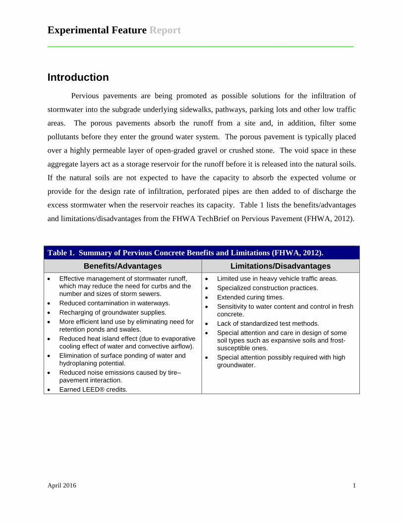
Introduction Pervious pavements are being promoted as possible solutions for the infiltration of
stormwater into the subgrade underlying sidewalks, pathways, parking lots and other low traffic
areas. The porous pavements absorb the runoff from a site and, in addition, filter some
pollutants before they enter the ground water system. The porous pavement is typically placed
over a highly permeable layer of open-graded gravel or crushed stone. The void space in these
aggregate layers act as a storage reservoir for the runoff before it is released into the natural soils.
If the natural soils are not expected to have the capacity to absorb the expected volume or
provide for the design rate of infiltration, perforated pipes are then added to of discharge the
excess stormwater when the reservoir reaches its capacity. Table 1 lists the benefits/advantages
and limitations/disadvantages from the FHWA TechBrief on Pervious Pavement (FHWA, 2012).
Table 1. Summary of Pervious Concrete Benefits and Limitations (FHWA, 2012).
Benefits/Advantages Limitations/Disadvantages • Effective management of stormwater runoff,
which may reduce the need for curbs and the number and sizes of storm sewers.
• Reduced contamination in waterways. • Recharging of groundwater supplies. • More efficient land use by eliminating need for
retention ponds and swales. • Reduced heat island effect (due to evaporative
cooling effect of water and convective airflow). • Elimination of surface ponding of water and
hydroplaning potential. • Reduced noise emissions caused by tire–
pavement interaction. • Earned LEED® credits.
• Limited use in heavy vehicle traffic areas. • Specialized construction practices. • Extended curing times. • Sensitivity to water content and control in fresh
concrete. • Lack of standardized test methods. • Special attention and care in design of some
soil types such as expansive soils and frost-susceptible ones.
• Special attention possibly required with high groundwater.

Experimental Feature Report __________________________________________________________
April 2016 2
Project Location The City of Monroe, WA has embarked on a plan to systematically replace many of the
sidewalks and parking strips in their downtown area with pervious pavement alternatives. The
2015 project replaced the parking strips and sidewalks on portions of Lewis and Main Streets in
the urban core of Monroe (Figure 1). WSDOT has an interest in this project because Lewis
Street is State Route (SR) 203 which runs north from SR 202 in Fall City to its terminus at SR 2.
WSDOT has responsibility/jurisdiction of the roadway from curb line to curb line for state routes
that are within a city limit and thus, includes the installed pervious pavement on the SR 203,
Lewis Street section. However, the City of Monroe has the responsibility for all maintenance of
the parking strips as per a maintenance agreement between the City and WSDOT (see Appendix
A, Maintenance Agreement). Table 2 is a quick reference for facts concerning the project.
Table 2. Project facts. State Route SR 203 Contract Number City of Monroe project, no WSDOT contract no. Milepost Limits 23.82 to 24.00 in both directions Construction Pervious concrete parking strips on Lewis Street Contractor Road Construction NW Inc., Renton, WA Concrete Supplier Cadman, Sky River Plant, Monroe, WA Concrete Thickness 8.5 inches Ballast Storage Bed Thickness 21-30 inches Construction Period Summer, 2015 Auxiliary Evaluation PaveDrain® concrete block system on Main Street

Experimental Feature Report __________________________________________________________
April 2016 3
Figure 1. Project location. On Lewis Street the blue denotes the permeable concrete parking strips and sidewalks. On Main Street the yellow is the PaveDrain® permeable block parking strips. (Photo courtesy of City of Monroe)
Study Objectives The objectives of this study are to evaluate (1) the performance of the pervious concrete
parking strips with respect to infiltration capacity, (2) the performance of the parking strips with
Experimental Feature Report __________________________________________________________
April 2016 4
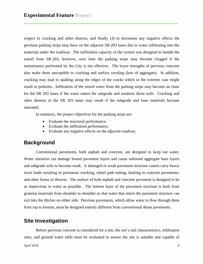
respect to cracking and other distress, and finally (3) to document any negative effects the
pervious parking strips may have on the adjacent SR-203 lanes due to water infiltrating into the
materials under the roadway. The infiltration capacity of the system was designed to handle the
runoff from SR-203, however, over time the parking strips may become clogged if the
maintenance performed by the City is not effective. The lower strengths of pervious concrete
also make them susceptible to cracking and surface raveling (loss of aggregate). In addition,
cracking may lead to spalling along the edges of the cracks which in the extreme case might
result in potholes. Infiltration of the stored water from the parking strips may become an issue
for the SR 203 lanes if the water enters the subgrade and weakens those soils. Cracking and
other distress in the SR 203 lanes may result if the subgrade and base materials become
saturated.
In summary, the project objectives for the parking strips are:
• Evaluate the structural performance. • Evaluate the infiltration performance. • Evaluate any negative effects on the adjacent roadway.
Background Conventional pavements, both asphalt and concrete, are designed to keep out water.
Water intrusion can damage bound pavement layers and cause unbound aggregate base layers
and subgrade soils to become weak. A damaged or weak pavement structure cannot carry heavy
truck loads resulting in premature cracking, wheel path rutting, faulting in concrete pavements,
and other forms of distress. The surface of both asphalt and concrete pavement is designed to be
as impervious to water as possible. The bottom layer of the pavement structure is built from
granular materials from shoulder to shoulder so that water that enters the pavement structure can
exit into the ditches on either side. Pervious pavements, which allow water to flow through them
from top to bottom, must be designed entirely different from conventional dense pavements.
Site Investigation Before pervious concrete is considered for a site, the site’s soil characteristics, infiltration
rates, and ground water table must be evaluated to ensure the site is suitable and capable of
Experimental Feature Report __________________________________________________________
April 2016 5
infiltrating stormwater. Infiltrating stormwater is not possible in locations where the underlying
soils are not impermeable. The materials underlying the City of Monroe parking strips were
investigated to determine if the subsurface conditions were compatible with infiltration of large
quantities of stormwater. The consulting firm of Robinson Noble, Woodinville, WA was hired
to provide the geotechnical information necessary to assess the site. The conclusion reached was
that the site, which is underlain by medium dense to very dense sands and gravels, is suitable for
infiltration and pavement support. Well-drained unsaturated soils extended to depths of 14 feet
below ground surface with infiltration rate for samples from six borings averaging 2.2 inches per
hour with a range of from 0.7 to 6.5 inches per hour. Ground water levels were measured at
depths of 14 feet or greater below the ground surface, providing a zone for the movement of
substantial quantities of water into the soils from the pervious parking strips (Appendix B).
(Note that only the text portion of the report is reproduced in the appendix).
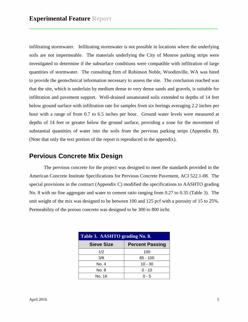
Pervious Concrete Mix Design The pervious concrete for the project was designed to meet the standards provided in the
American Concrete Institute Specifications for Pervious Concrete Pavement, ACI 522.1-08. The
special provisions in the contract (Appendix C) modified the specifications to AASHTO grading
No. 8 with no fine aggregate and water to cement ratio ranging from 0.27 to 0.35 (Table 3). The
unit weight of the mix was designed to be between 100 and 125 pcf with a porosity of 15 to 25%.
Permeability of the porous concrete was designed to be 300 to 800 in/hr.
Table 3. AASHTO grading No. 8.
Sieve Size Percent Passing 1/2 100 3/8 85 - 100
No. 4 10 - 30 No. 8 0 - 10
No. 16 0 - 5

Experimental Feature Report __________________________________________________________
April 2016 6
Construction A typical cross section of the parking strips is shown in Figure 2. The 6 foot wide, 8.5
inch thick pervious concrete parking strips sit on a layer of permeable ballast that varied in depth
between 21 and 30 inches with most areas being 21 inches. The permeable ballast ranged in size
from 3/4 to 2 inches with a fracture requirement of one face on 75 percent of the aggregate
(Table 4). Figure 3 is a close-up photo of the permeable ballast.
Figure 2. Cross section of the parking strip installation on Lewis Street.
Table 4. Permeable ballast specification.
Sieve Size Percent Passing 2-1/2 99 - 100
2 65 - 100 3/4 40 - 80
No. 4 5 max. No. 100 0 - 2
% Fracture 75 min.

Experimental Feature Report __________________________________________________________
April 2016 7
Figure 3. Permeable ballast close-up. (Photo courtesy of Joe Mahoney, UW)
The project was constructed by Road Construction NW with Cadman supplying the
concrete from their Sky River plant in Monroe. The construction of the parking strips began
with excavation of the area adjacent to the SR 203 roadway. The parking strips and the
sidewalks were both being replaced with pervious concrete; therefore, the areas excavated in
some cases extended to the edge of the buildings housing businesses (see Figure 4-5). Pipes and
other utilities were relocated or worked around. Figure 6 shows the excavation of the 21 inch
deep permeable ballast storage reservoir upon which the parking strips were built. Excavation
was followed by the placement of the permeable ballast (Figures 7).
Experimental Feature Report __________________________________________________________
April 2016 8
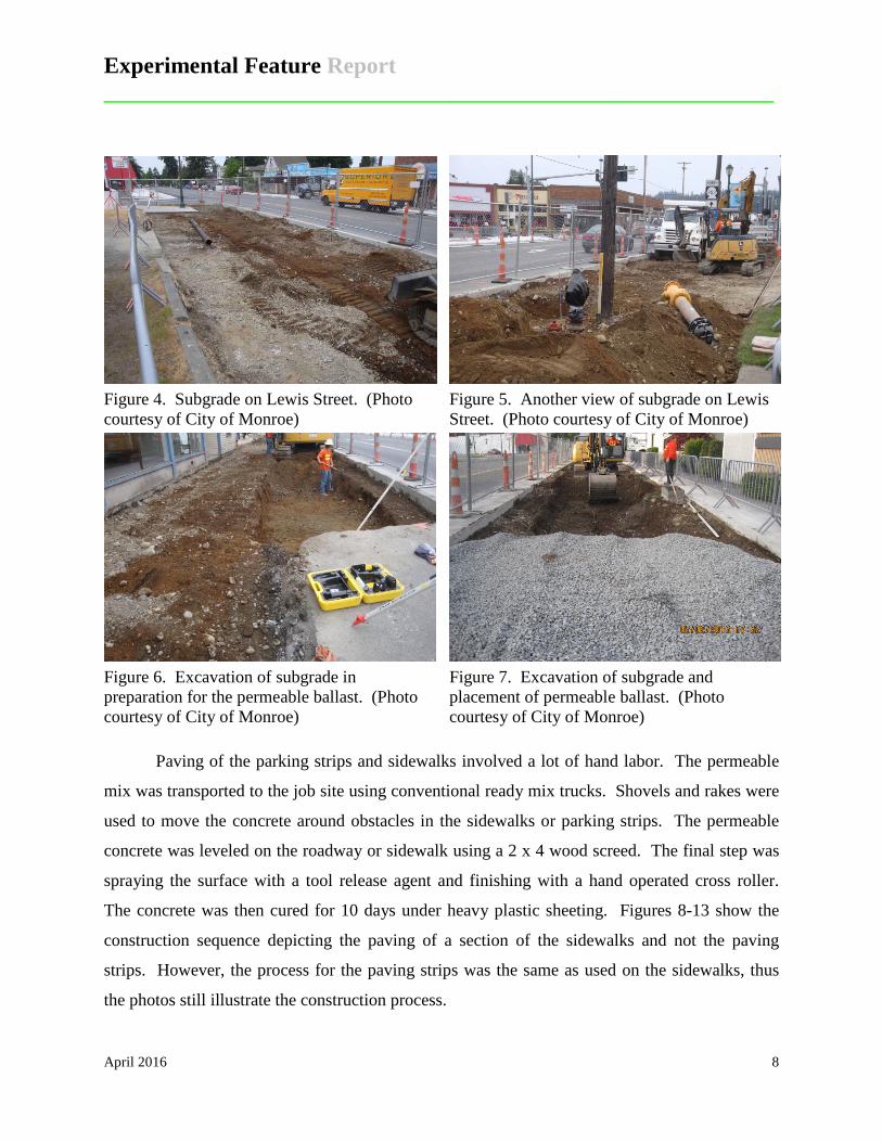
Figure 4. Subgrade on Lewis Street. (Photo courtesy of City of Monroe)
Figure 5. Another view of subgrade on Lewis Street. (Photo courtesy of City of Monroe)
Figure 6. Excavation of subgrade in preparation for the permeable ballast. (Photo courtesy of City of Monroe)
Figure 7. Excavation of subgrade and placement of permeable ballast. (Photo courtesy of City of Monroe)
Paving of the parking strips and sidewalks involved a lot of hand labor. The permeable
mix was transported to the job site using conventional ready mix trucks. Shovels and rakes were
used to move the concrete around obstacles in the sidewalks or parking strips. The permeable
concrete was leveled on the roadway or sidewalk using a 2 x 4 wood screed. The final step was
spraying the surface with a tool release agent and finishing with a hand operated cross roller.
The concrete was then cured for 10 days under heavy plastic sheeting. Figures 8-13 show the
construction sequence depicting the paving of a section of the sidewalks and not the paving
strips. However, the process for the paving strips was the same as used on the sidewalks, thus
the photos still illustrate the construction process.

Experimental Feature Report __________________________________________________________
April 2016 9
Figure 8. Cadman ready mix truck delivering pervious concrete. (Photo courtesy of Joe Mahoney, UW)
Figure 9. Raking and screeding of delivered concrete. (Photo courtesy of Joe Mahoney, UW)
Figure 10. Screed board is a wood 2 X 4. (Photo courtesy of Joe Mahoney, UW)
Figure 11. Hand troweling of pervious concrete. (Photo courtesy of Joe Mahoney, UW)

Experimental Feature Report __________________________________________________________
April 2016 10
Figure 12. Roller used to smooth the surface of the pervious concrete. A tool release agent was sprayed on the mix prior to rolling. (Photo courtesy of Joe Mahoney, UW)
Figure 13. Plastic sheeting used to cure the pervious concrete for 10 days. (Photo courtesy of Joe Mahoney, UW)
Figures 14-17 are additional photos of the paving of the parking strips on Lewis Street.
Forms were installed to separate the parking strip concrete from the HMA yet to be placed
between the parking strip and the existing SR 203 lane.
Figure 14. Forms in place on Lewis Street for the parking strips. (Photo courtesy of City of Monroe)
Figure 15. Concrete truck delivering pervious concrete to the forms. (Photo courtesy of City of Monroe)

Experimental Feature Report __________________________________________________________
April 2016 11
Figure 16. Distributing the pervious concrete in the forms with rakes and shovels. (Photo courtesy of City of Monroe)
Figure 17. Finished parking strip at an intersection. (Photo courtesy of City of Monroe)
Figures 18-21 show the finished parking strips, sidewalks and other items included in the
construction of the project. Note that driveways crossing the sidewalks were paved with
conventional dense concrete to carry the heavier loads of vehicles using the driveways. Also
note the HMA placed between the parking strip and the existing SR 203 lane.
Figure 18. Finished parking strip on Lewis Street. Note HMA filler between SR 203 lane and the parking strip. (Photo courtesy of Joe Mahoney, UW)
Figure 19. Another view of the parking strip on Lewis Street. (Photo courtesy of Joe Mahoney, UW)

Experimental Feature Report __________________________________________________________
April 2016 12
Figure 20. Driveway of dense concrete crossing pervious concrete sidewalk on Lewis Street. (Photo courtesy of Joe Mahoney, UW)
Figure 21. Sidewalk and parking strip on Lewis Street. (Photo courtesy of Joe Mahoney, UW)
Construction Challenges Construction of the project was not without challenges. Figure 22 shows a void under the
SR 203 mainline that was uncovered during the excavation of the parking strip on the east side
between Main and Fremont Streets. Jeff Uhlmeyer, State Pavements Engineer, observed the
void and recommended to the City of Monroe that the pavement above the void be removed and
the base materials compacted prior to the paving of the HMA filler strip between the parking
strip and SR 203 mainline. The cost of this fix was out of the scope of the contract and after a
discussion with WSDOT it was decided that someone from Maintenance would be sent out to
suggest a solution. Maintenance suggestion was that the contractor should try to fill the void
with gravel, which was done, and that the State crews would come out and fix the depressed and
cracked area of pavement. At the time of the writing of this report the depressed and cracked
pavement has not been fixed (Figure 23).

Experimental Feature Report __________________________________________________________
April 2016 13
Figure 22. Void space under SR 203. Figure 23. Sealed crack in HMA on SR 203.
Auxiliary Evaluation The performance of the other pervious concrete features such as the sidewalks and
PaveDrain® parking strips will also be noted during the evaluation of the parking strips.
PaveDrain® is a proprietary product used by the City of Monroe on the parking strips of the Main
Street portion of the project. WSDOT has an interest in all types of pervious pavement as
possible infiltration solutions for stormwater generated from transportation facilities.
PaveDrain® is a permeable pavement system comprised of articulated concrete blocks connected
into mats using polyester cables (Figure 24). The cables provide a consistent 1/4 inch wide joint
between the individual blocks. Each concrete block houses an arched reservoir which increases
the storage capacity of the system above and beyond the storage capacity of the aggregate layer
(Figure 25). Each block is 12” by 12” by 5.5” with a weight of 45 pounds.

Experimental Feature Report __________________________________________________________
April 2016 14
Figure 24. PaveDrain® mat with lifting gear. (Photo courtesy of Joe Mahoney, UW)
Figure 25. Side view of block showing arched reservoir (photo from PaveDrain® website).
The 1/4 inch joint between the blocks is within ADA requirements for the protection of
those in wheel chairs and using walkers. The spacing allows a significant amount of water to
drain down the sides of the blocks without becoming clogged with sediment particles. The
system design allows materials such as leaves, needles and seeds to be washed into the aggregate
bedding layer beneath the mat where they will biodegrade in the presence of moisture and air
(PaveDrain®, 2015).
The manufacturer recommends that the performance of the system be checked bi-
monthly, preferably during a rain event, to assess the amount of infiltration occurring.
PaveDrain® indicates that it could be years before maintenance needs to be performed if site
Experimental Feature Report __________________________________________________________
April 2016 15
conditions are favorable. A study by the University of Louisville compared the effectiveness of
three types of cleaning regiments for the PaveDrain® system; (1) vacuum and sweeping, (2)
pressurized air jet, and (3) vac head. The vac head was shown to be the best method. A 30 inch
diameter head mounted on caster wheels is attached to a vacuum truck to provide continuous
suction. The head contains spinning water nozzles that displace the debris in the joints which is
then suctioned up by the vacuum truck (Hamidreza, 2015).
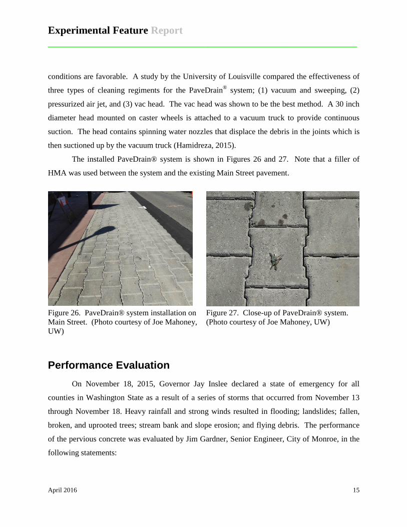
The installed PaveDrain® system is shown in Figures 26 and 27. Note that a filler of
HMA was used between the system and the existing Main Street pavement.
Figure 26. PaveDrain® system installation on Main Street. (Photo courtesy of Joe Mahoney, UW)
Figure 27. Close-up of PaveDrain® system. (Photo courtesy of Joe Mahoney, UW)
Performance Evaluation On November 18, 2015, Governor Jay Inslee declared a state of emergency for all
counties in Washington State as a result of a series of storms that occurred from November 13
through November 18. Heavy rainfall and strong winds resulted in flooding; landslides; fallen,
broken, and uprooted trees; stream bank and slope erosion; and flying debris. The performance
of the pervious concrete was evaluated by Jim Gardner, Senior Engineer, City of Monroe, in the
following statements:

Experimental Feature Report __________________________________________________________
April 2016 16
11/23/2015 “About three-quarters of the concrete appeared to infiltrate the water before any flow reached the gutter line. The remaining quarter had a small amount of ponding along the gutter. The intersection of Lewis and Main had puddles on the south side. The puddle on the SW corner covered the ADA ramp. The puddle on the SE corner stopped shy of the ADA ramp. Neither puddle reached the driving lane. The blocks on Main Street worked great. No ponding or flow observed at any point along the new parking strips” (word in italics added by author). 3/23/2016 “The pervious has not worked as well as I had hoped at the traffic light due to clogging of the surface voids. It must have something to do with the braking action causing vibrations that result in dirt and debris falling off the vehicles. The remainder of the area is working well. We have a new Cyclone sweeper that seems to do a good job cleaning the pervious. It has a pressurize spray head inside a cowling with a vacuum at the center of the head. The spray head loosens the particles and the vacuum draws the muck into a storage tank for disposal. We compared this unit to a regenerative sweeper and it is far superior. I am eager to see how it does cleaning the pavement at the light and if it will restore the permeability of the pavement.”
The City’s observations indicate that the pervious concrete performed as designed with some
ponding at the intersection of Main and Lewis Streets.
Future Research The work plan for the experimental feature (Appendix D) outlines evaluation of the
performance of the parking strips for a period of five years via annual visual inspections and
interviews with State Maintenance personnel. Cracking or other deterioration of the pervious
concrete will be documented. Any clogging of the parking strips which leads to the excessive
accumulation of stormwater will be noted. The performance of the PaveDrain® system and
pervious sidewalks will also be evaluated and reported. A final report will be issued at the end
of the performance period.

Experimental Feature Report __________________________________________________________
April 2016 17
References Federal Highway Administration, “FHWA TechBrief: Pervious Pavement” Office of Pavement
Technology, Washington D.C., December 2012
Kazemi, Hamidreza, Thomas Rockaway, and John Rivard, “Assessment of Infiltration Performance and Maintenance of Pavedrain Pavements for Two Application in Louisville, KY”, Center for Infrastructure Research, Civil and Environmental Engineering Department, University of Louisville, accessed June 2015.
PaveDrain® web site, http://pavedrain.com/ , accessed June 2015.

Experimental Feature Report __________________________________________________________
April 2016 18
Appendix A Maintenance Agreement
Experimental Feature Report __________________________________________________________
April 2016 19
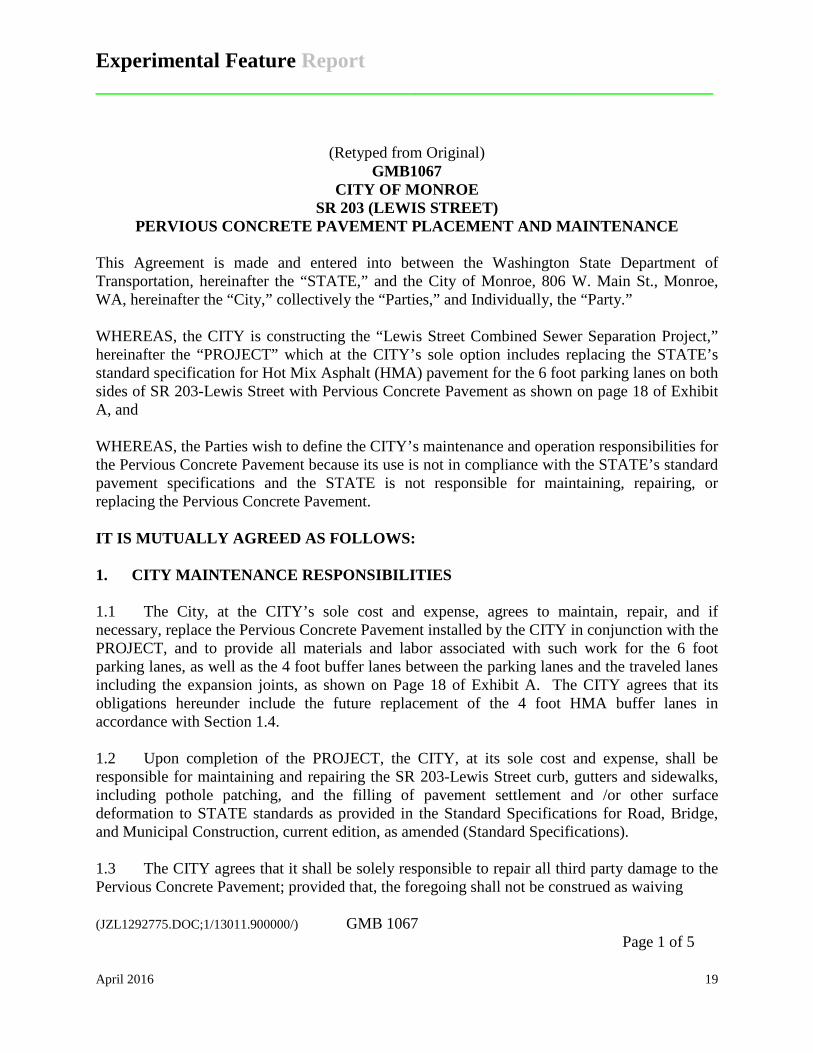
(Retyped from Original) GMB1067
CITY OF MONROE SR 203 (LEWIS STREET)
PERVIOUS CONCRETE PAVEMENT PLACEMENT AND MAINTENANCE
This Agreement is made and entered into between the Washington State Department of Transportation, hereinafter the “STATE,” and the City of Monroe, 806 W. Main St., Monroe, WA, hereinafter the “City,” collectively the “Parties,” and Individually, the “Party.” WHEREAS, the CITY is constructing the “Lewis Street Combined Sewer Separation Project,” hereinafter the “PROJECT” which at the CITY’s sole option includes replacing the STATE’s standard specification for Hot Mix Asphalt (HMA) pavement for the 6 foot parking lanes on both sides of SR 203-Lewis Street with Pervious Concrete Pavement as shown on page 18 of Exhibit A, and WHEREAS, the Parties wish to define the CITY’s maintenance and operation responsibilities for the Pervious Concrete Pavement because its use is not in compliance with the STATE’s standard pavement specifications and the STATE is not responsible for maintaining, repairing, or replacing the Pervious Concrete Pavement. IT IS MUTUALLY AGREED AS FOLLOWS: 1. CITY MAINTENANCE RESPONSIBILITIES 1.1 The City, at the CITY’s sole cost and expense, agrees to maintain, repair, and if necessary, replace the Pervious Concrete Pavement installed by the CITY in conjunction with the PROJECT, and to provide all materials and labor associated with such work for the 6 foot parking lanes, as well as the 4 foot buffer lanes between the parking lanes and the traveled lanes including the expansion joints, as shown on Page 18 of Exhibit A. The CITY agrees that its obligations hereunder include the future replacement of the 4 foot HMA buffer lanes in accordance with Section 1.4. 1.2 Upon completion of the PROJECT, the CITY, at its sole cost and expense, shall be responsible for maintaining and repairing the SR 203-Lewis Street curb, gutters and sidewalks, including pothole patching, and the filling of pavement settlement and /or other surface deformation to STATE standards as provided in the Standard Specifications for Road, Bridge, and Municipal Construction, current edition, as amended (Standard Specifications). 1.3 The CITY agrees that it shall be solely responsible to repair all third party damage to the Pervious Concrete Pavement; provided that, the foregoing shall not be construed as waiving (JZL1292775.DOC;1/13011.900000/) GMB 1067 Page 1 of 5
Experimental Feature Report __________________________________________________________
April 2016 20
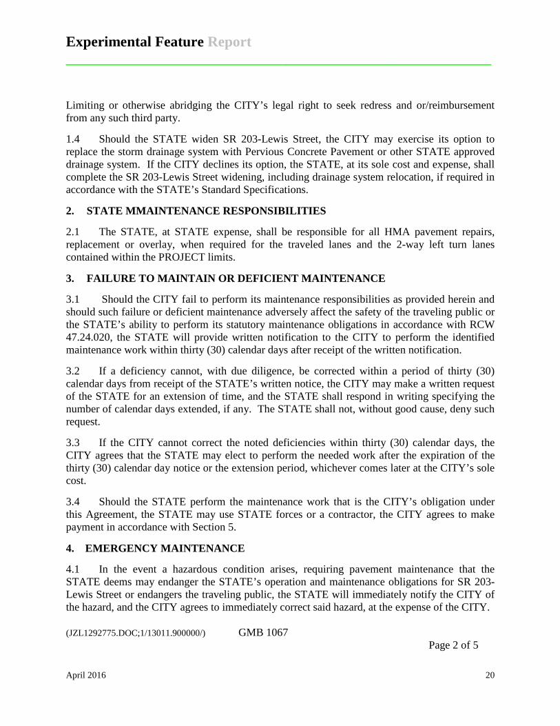
Limiting or otherwise abridging the CITY’s legal right to seek redress and or/reimbursement from any such third party. 1.4 Should the STATE widen SR 203-Lewis Street, the CITY may exercise its option to replace the storm drainage system with Pervious Concrete Pavement or other STATE approved drainage system. If the CITY declines its option, the STATE, at its sole cost and expense, shall complete the SR 203-Lewis Street widening, including drainage system relocation, if required in accordance with the STATE’s Standard Specifications. 2. STATE MMAINTENANCE RESPONSIBILITIES 2.1 The STATE, at STATE expense, shall be responsible for all HMA pavement repairs, replacement or overlay, when required for the traveled lanes and the 2-way left turn lanes contained within the PROJECT limits. 3. FAILURE TO MAINTAIN OR DEFICIENT MAINTENANCE 3.1 Should the CITY fail to perform its maintenance responsibilities as provided herein and should such failure or deficient maintenance adversely affect the safety of the traveling public or the STATE’s ability to perform its statutory maintenance obligations in accordance with RCW 47.24.020, the STATE will provide written notification to the CITY to perform the identified maintenance work within thirty (30) calendar days after receipt of the written notification. 3.2 If a deficiency cannot, with due diligence, be corrected within a period of thirty (30) calendar days from receipt of the STATE’s written notice, the CITY may make a written request of the STATE for an extension of time, and the STATE shall respond in writing specifying the number of calendar days extended, if any. The STATE shall not, without good cause, deny such request. 3.3 If the CITY cannot correct the noted deficiencies within thirty (30) calendar days, the CITY agrees that the STATE may elect to perform the needed work after the expiration of the thirty (30) calendar day notice or the extension period, whichever comes later at the CITY’s sole cost. 3.4 Should the STATE perform the maintenance work that is the CITY’s obligation under this Agreement, the STATE may use STATE forces or a contractor, the CITY agrees to make payment in accordance with Section 5. 4. EMERGENCY MAINTENANCE 4.1 In the event a hazardous condition arises, requiring pavement maintenance that the STATE deems may endanger the STATE’s operation and maintenance obligations for SR 203-Lewis Street or endangers the traveling public, the STATE will immediately notify the CITY of the hazard, and the CITY agrees to immediately correct said hazard, at the expense of the CITY. (JZL1292775.DOC;1/13011.900000/) GMB 1067 Page 2 of 5

Experimental Feature Report __________________________________________________________
April 2016 21
4.2 If the CITY’s Public Works Director, or such official’s functional successor is contacted and CITY forces are not available to perform emergency maintenance, the STATE reserves the right, at the CITY’s sole cost and expense, to perform the necessary emergency maintenance to the extent necessary to allow for the normal operation of SR 203-Lewis Street and the safety of the traveling public. Should the STATE perform such maintenance, the CITY agrees to make payment in accordance with Section 5. 5. PAYMENT 5.1 The CITY agrees to and shall make payment to the STATE for the actual direct and related indirect costs of any work covered under Sections 3.4, 4.2 and 11.2 of this Agreement. The STATE shall provide the CITY with a detailed invoice for the STATE maintenance work performed, and the CITY agrees to make payment within thirty (30) calendar days after the date of a detailed STATE invoice. 5.2 If the CITY objects to all or any portion of an invoice, it shall notify the STATE in writing within twenty (20) calendar days from the date of invoice receipt and shall pay that portion of the invoice not in dispute. The STATE and the CITY shall immediately make every effort to settle the disputed portion, and if necessary, utilize the dispute resolution process in Section 10. 5.3 The CITY agrees that if it does not make payment on undisputed portions of an invoice within ninety (90) calendar days after invoice receipt, the STATE may deduct and expend any monies to which the CITY is entitled to receive from the Motor Vehicle Fund as Authorized by RCW 47.24.050. 6. TERMINATION 6.1 This agreement may be terminated only if mutually agreed to by the Parties. Conditions of termination shall be mutually agreed upon in writing and shall not be binding unless signed by person authorized to bind each of the Parties. 6.2 Any termination of this Agreement shall not prejudice any rights or obligations accrued to the Parties prior to termination. 7. MODIFICATIONS AND WAIVERS 7.1 This Agreement constitutes the entire agreement between the Parties on the subject matter hereof. There are no understandings, agreements, or representations, oral or written, not specified herein regarding this Agreement. No waiver, consent, modification, or change of terms of this Agreement shall bind either Party unless in writing and signed by both Parties. Such waiver, consent, modification, or change, if made, shall be effective only in the specific instance and for the specific purpose given. The failure of either Party to enforce any provision of this Agreement shall not constitute a waiver by the Party of that or any other provision. (JZL1292775.DOC;1/13011.900000/) GMB 1067 Page 3 of 5

Experimental Feature Report __________________________________________________________
April 2016 22
8. ASSIGNMENT
8.1 Neither Party shall transfer or assign any right or obligation under this Agreement without the prior written consent of the other Party.
9. SEVERABILITY 9.1 Should any part, term, or provision of this Agreement be determined to be invalid, the remainder of this Agreement shall not be affected, and the same shall continue in full force and effect.
10. DISPUTE RESOLUTION
10.1 In the event that a dispute arises under this Agreement, it shall be resolved as follows:
The CITY and the STATE shall each appoint a member to a Disputes Board; these two members shall select a third member not affiliated with either Party. The three members to the Disputes Board shall conduct a dispute resolution hearing that shall be informal and unrecorded. An attempt at such dispute resolution in compliance with this process shall be a prerequisite to the filing of litigation concerning the dispute. The Parties shall equally share in the cost of the third Disputes Board member; however, each party shall be responsible for its own costs and fees.
11. LEGAL RELATIONS
11.1 The CITY shall protect, defend, indemnify, and hold harmless the STATE, its officers, officials, employees and agents, while acting within the scope of their employment as such, from any and all costs, claims, judgments, and/or awards of damages (both to persons and/or property), arising out of, or in any way resulting from the CITY’s replacement of the HMA with Pervious Concrete Pavement on SR 203-Lewis Street right of way and the City’s maintenance, repair and/or replacement maintenance work performed or to be performed pursuant to the provisions of this Agreement. The CITY will not be required to indemnify, defend, or hold harmless the STATE to the extent that the claim, suit, or action for injuries, death, or damages (both to person and/or property) is caused by the negligence of the STATE. Where such claims, suits or actions result from concurrent negligence of both Parties, or involves those actions covered by RCW4.24.115, the indemnity provisions provided herein shall be valid and enforceable only to the extent of each Party’s own negligence.
The STATE shall protect, defend, indemnify, and hold harmless the CITY, its officers, officials, employees and agents, while acting within the scope of their employment as such, from any and all costs, claims, judgments, and/or awards of damages (both to persons and/or property), arising out of, or in any way resulting from any work performed or caused to be performed by the STATE under this Agreement. The STATE will not be required to indemnify, defend, or hold harmless the CITY to the extent that the claim, suit, or action for injuries, death, or damages (both to persons and/or property) is caused by the negligence of the CITY. Where such claims, suits, or actions result from concurrent negligence of both Parties, or involves those actions covered by RCW 4.24.115, the indemnity provisions herein shall be valid and
(JZL1292775.DOC;1/13011.900000/) GMB 1067 Page 4 of 5
Experimental Feature Report __________________________________________________________
April 2016 23
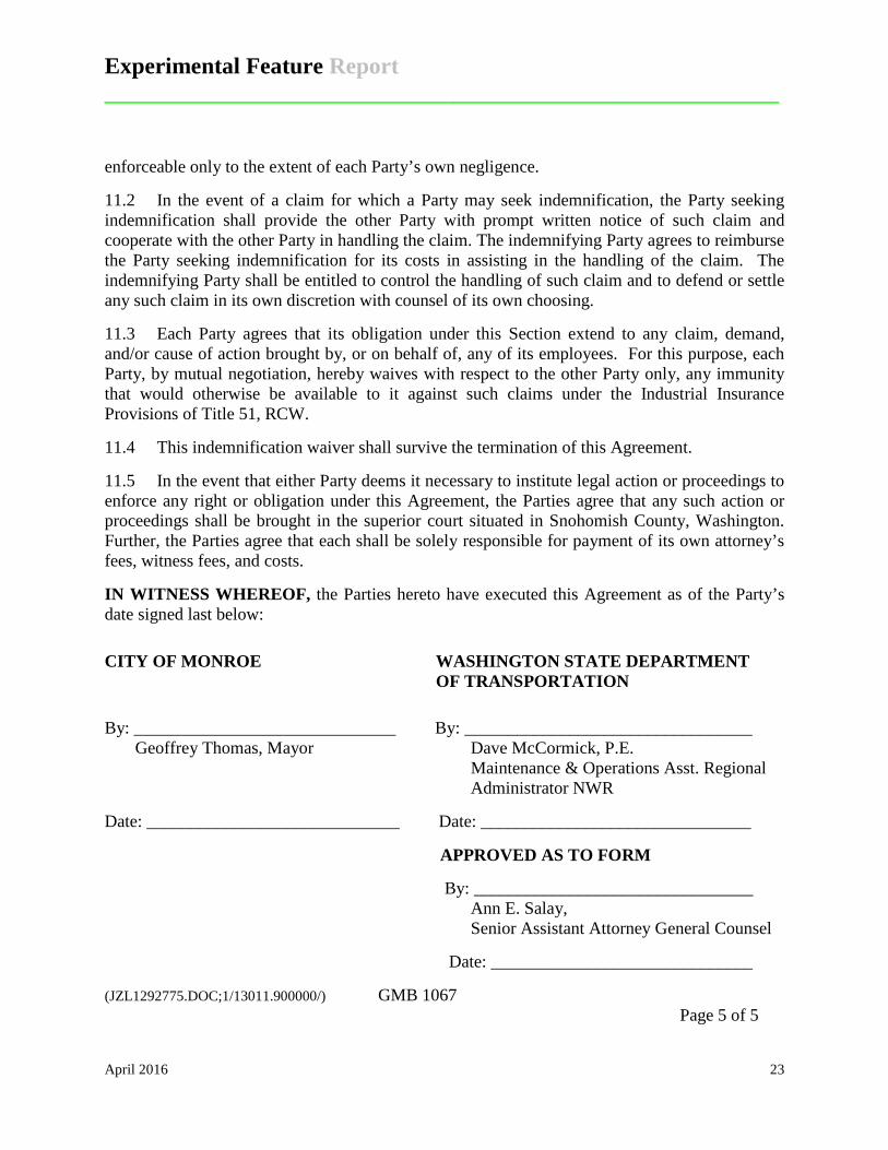
enforceable only to the extent of each Party’s own negligence. 11.2 In the event of a claim for which a Party may seek indemnification, the Party seeking indemnification shall provide the other Party with prompt written notice of such claim and cooperate with the other Party in handling the claim. The indemnifying Party agrees to reimburse the Party seeking indemnification for its costs in assisting in the handling of the claim. The indemnifying Party shall be entitled to control the handling of such claim and to defend or settle any such claim in its own discretion with counsel of its own choosing. 11.3 Each Party agrees that its obligation under this Section extend to any claim, demand, and/or cause of action brought by, or on behalf of, any of its employees. For this purpose, each Party, by mutual negotiation, hereby waives with respect to the other Party only, any immunity that would otherwise be available to it against such claims under the Industrial Insurance Provisions of Title 51, RCW. 11.4 This indemnification waiver shall survive the termination of this Agreement. 11.5 In the event that either Party deems it necessary to institute legal action or proceedings to enforce any right or obligation under this Agreement, the Parties agree that any such action or proceedings shall be brought in the superior court situated in Snohomish County, Washington. Further, the Parties agree that each shall be solely responsible for payment of its own attorney’s fees, witness fees, and costs. IN WITNESS WHEREOF, the Parties hereto have executed this Agreement as of the Party’s date signed last below: CITY OF MONROE WASHINGTON STATE DEPARTMENT
OF TRANSPORTATION
By: ______________________________ By: _________________________________ Geoffrey Thomas, Mayor Dave McCormick, P.E.
Maintenance & Operations Asst. Regional Administrator NWR
Date: _____________________________ Date: _______________________________ APPROVED AS TO FORM By: ________________________________
Ann E. Salay, Senior Assistant Attorney General Counsel Date: ______________________________ (JZL1292775.DOC;1/13011.900000/) GMB 1067 Page 5 of 5

Experimental Feature Report __________________________________________________________
April 2016 24
Appendix B Geotechnical Report

Experimental Feature Report __________________________________________________________
April 2016 25
(Retyped from Original)
GEOTECHNICAL ENGINEERING REPORT LEWIS STREET COMBINED SEWER SEPARATION
MONROE, WASHINGTON FOR
CITY OF MONROE MARCH 2014
Experimental Feature Report __________________________________________________________
April 2016 26
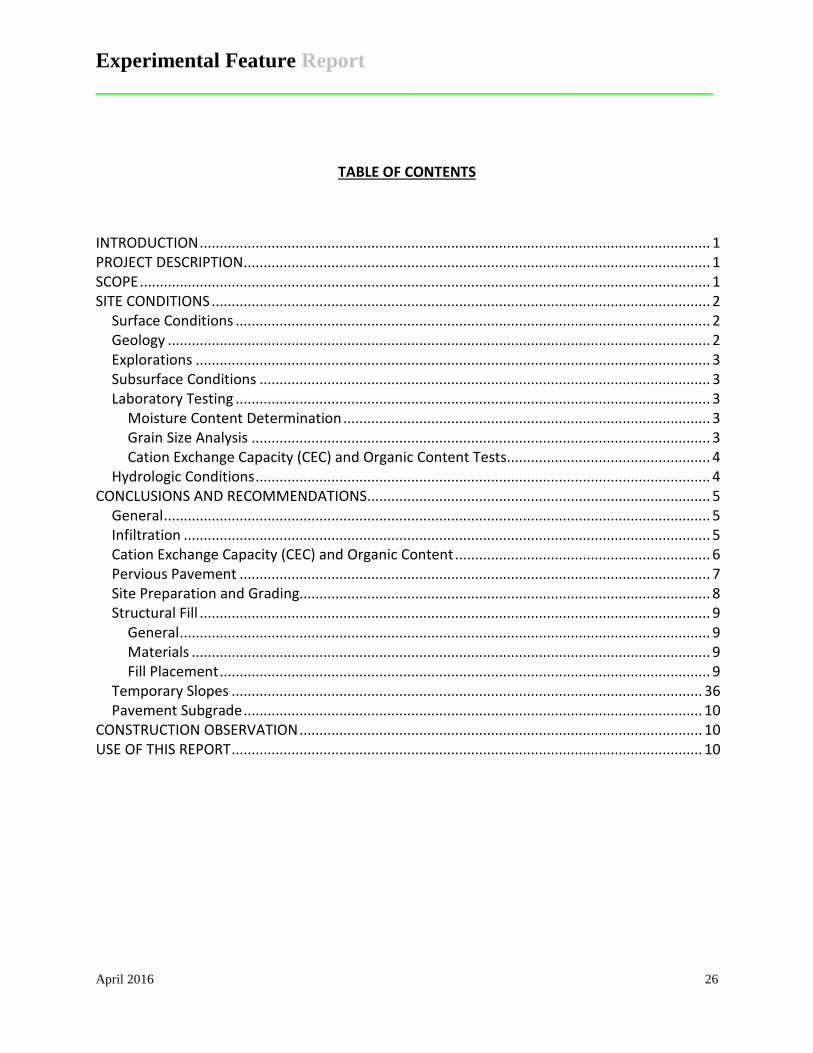
TABLE OF CONTENTS
INTRODUCTION ................................................................................................................................ 1 PROJECT DESCRIPTION ..................................................................................................................... 1 SCOPE ............................................................................................................................................... 1 SITE CONDITIONS ............................................................................................................................. 2
Surface Conditions ....................................................................................................................... 2 Geology ........................................................................................................................................ 2 Explorations ................................................................................................................................. 3 Subsurface Conditions ................................................................................................................. 3 Laboratory Testing ....................................................................................................................... 3
Moisture Content Determination ............................................................................................ 3 Grain Size Analysis ................................................................................................................... 3 Cation Exchange Capacity (CEC) and Organic Content Tests ................................................... 4
Hydrologic Conditions .................................................................................................................. 4 CONCLUSIONS AND RECOMMENDATIONS ...................................................................................... 5
General ......................................................................................................................................... 5 Infiltration .................................................................................................................................... 5 Cation Exchange Capacity (CEC) and Organic Content ................................................................ 6 Pervious Pavement ...................................................................................................................... 7 Site Preparation and Grading....................................................................................................... 8 Structural Fill ................................................................................................................................ 9
General ..................................................................................................................................... 9 Materials .................................................................................................................................. 9 Fill Placement ........................................................................................................................... 9
Temporary Slopes ...................................................................................................................... 36 Pavement Subgrade ................................................................................................................... 10
CONSTRUCTION OBSERVATION ..................................................................................................... 10 USE OF THIS REPORT ...................................................................................................................... 10

Experimental Feature Report __________________________________________________________
April 2016 27
INTRODUCTION This report presents the results of our geotechnical engineering investigation at your Lewis Street Combined Sewer Separation project, in the Monroe area of Snohomish County, Washington. The site is located on North Lewis Street from the alley north of East Main Street to about 200 feet south of East Fremont Street and on East Main Street from the west side of North Lewis Street to the west side of South Ferry Avenue, as shown on the Vicinity Map in Figure 1. You have requested that we complete this report to evaluate subsurface conditions and provide recommendations for site development. For our use in preparing this report, we have been provided with a roadway section plan prepared by the Washington State Highway Commission dated August 15, 1957 that shows the roadway cross section for old State Highway No. 15-B, now known as State Route 203 (Lewis Street). PROJECT DESCRIPTION The development is planned to consist of parking area improvements to North Lewis Street and East Main Street. The improvements include separation of stormwater from the sanitary sewer and parking lane reconstruction. The new permeable parking lane will consist of an approximate 10-foot wide parallel parking lane along both sides of North Lewis Street and an approximate 16-foot wide angled parking lane along both sides of East Main Street. Pervious parking is planned to abut the existing drive lanes, although it may be held 2 to 3 feet from the driving lane as a construction buffer because of raveling concerns. North Lewis Street may be approved by WSDOT as a test section for permeable concrete parking. We have therefore included recommendations for flow separation from the permeable parking lane and underlying infiltration reservoir to the main drive lanes. SCOPE The purpose of this study is to explore and characterize the subsurface conditions and present recommendations for site development. Specifically, our scope of services as outlined in our Services Agreement, dated December 30, 2013 includes the following:
• Review available geologic maps for the site. • Evaluate the subsurface soil and groundwater conditions in the area of the planned
infiltration facilities. • Evaluate pertinent physical and engineering characteristics of the soils encountered in the
borings. • Complete grain-size distribution curves in accordance with ASTM D-422
assign typical infiltration rates to the subsurface materials. • Complete Cation Exchange Capacity (CEC) tests (USEPA Method 9081) • Complete organic content tests (ASTM D-2974)
• Prepare a geotechnical report summarizing our conclusions and recommendations.

Experimental Feature Report __________________________________________________________
April 2016 28
Geotechnical Engineering Report Lewis Street Combined Sewer Separation Monroe, Washington March 3, 2014 RN File No. 1617-003A Page 2 SITE CONDITIONS Surface Conditions The project alignment is comprised of approximately 700 feet of North Lewis Street south from the alley north of East Main Street and 400 feet of East Main Street east from its intersection with North Lewis Street. The site is primarily a retail shopping area. The ground surface within the site is generally flat. Geology Most of the Puget Sound Region was affected by past intrusion of continental glaciation. The last period of glaciation, the Vashon Stade of the Fraser Glaciation, ended approximately 14,000 years ago. Many of the geomorphic features seen today are a result of scouring and overriding by glacial ice. During the Vashon Stade, areas of the Puget Sound region were overridden by over 3,000 feet of ice. Soil layers overridden by the ice sheet were compacted by a much greater extent than those that were not. Part of a typical glacial sequence within the area of the site included the following soil deposits from newest to oldest.
Artificial Fill (af) – Fill material is often locally placed by human activities, consistency will depend on the source of the fill. The thickness and expanse of this material will be dependent on the extent of fill required to grade land to the desired elevations. Density of the fill will depend on earthwork activities and compaction efforts made during the placement of the material. Recessional Glaciolacustrine (Qglr) – These soils were deposited in proglacial lakes. The soft silt, clayey silt, sandy silt and silty sand deposits typically include scattered dropstones. Recessional deposits were not deposited by the glacier and are typically not as dense as those that were. Recessional Outwash Sand (QPgos) – These deposits were derived from the stagnating and receding Vashon Glacier and consists mostly of stratified sand and gravel, but include unstratified ablation and melt-out deposits. Recessional deposits were not compacted by the glacier and are typically not as dense as those that were. These recessional outwash deposits are divided locally into:
Deltaic Outwash and Kame Deltas (Qgod) – These deposits are moderately to well sorted and consist of sand and gravel. Fluvial Outwash (Qgof) – These moderately to well stratified deposits range in size from sand to boulders.
The geologic units for this area are mapped on the Geologic Map of the Monroe 7.5 Minute Quadrangle, King and Snohomish Counties, Washington, by Joe D. Dragovivh, et al, (Washington Department of Natural Resources, November 2011). The site is mapped as being underlain by deltaic outwash and kame deltas. Our site explorations encountered deltaic outwash deposits.
Experimental Feature Report __________________________________________________________
April 2016 29
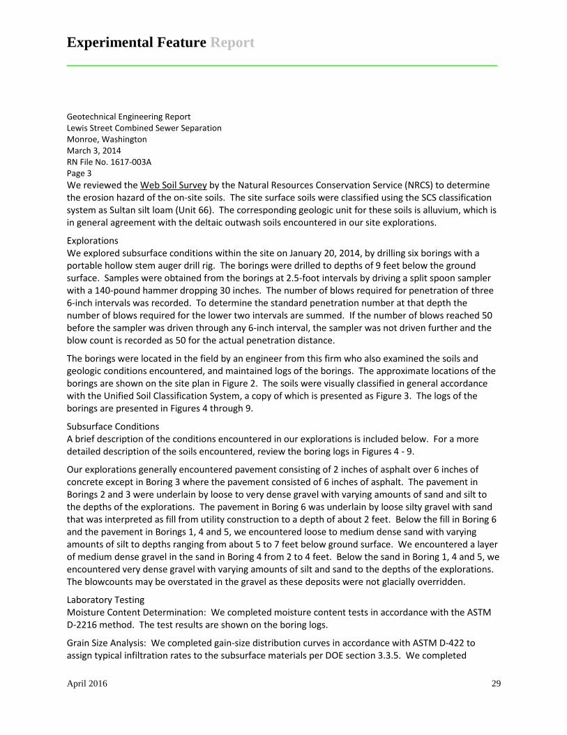
Geotechnical Engineering Report Lewis Street Combined Sewer Separation Monroe, Washington March 3, 2014 RN File No. 1617-003A Page 3 We reviewed the Web Soil Survey by the Natural Resources Conservation Service (NRCS) to determine the erosion hazard of the on-site soils. The site surface soils were classified using the SCS classification system as Sultan silt loam (Unit 66). The corresponding geologic unit for these soils is alluvium, which is in general agreement with the deltaic outwash soils encountered in our site explorations.
Explorations We explored subsurface conditions within the site on January 20, 2014, by drilling six borings with a portable hollow stem auger drill rig. The borings were drilled to depths of 9 feet below the ground surface. Samples were obtained from the borings at 2.5-foot intervals by driving a split spoon sampler with a 140-pound hammer dropping 30 inches. The number of blows required for penetration of three 6-inch intervals was recorded. To determine the standard penetration number at that depth the number of blows required for the lower two intervals are summed. If the number of blows reached 50 before the sampler was driven through any 6-inch interval, the sampler was not driven further and the blow count is recorded as 50 for the actual penetration distance.
The borings were located in the field by an engineer from this firm who also examined the soils and geologic conditions encountered, and maintained logs of the borings. The approximate locations of the borings are shown on the site plan in Figure 2. The soils were visually classified in general accordance with the Unified Soil Classification System, a copy of which is presented as Figure 3. The logs of the borings are presented in Figures 4 through 9.
Subsurface Conditions A brief description of the conditions encountered in our explorations is included below. For a more detailed description of the soils encountered, review the boring logs in Figures 4 - 9.
Our explorations generally encountered pavement consisting of 2 inches of asphalt over 6 inches of concrete except in Boring 3 where the pavement consisted of 6 inches of asphalt. The pavement in Borings 2 and 3 were underlain by loose to very dense gravel with varying amounts of sand and silt to the depths of the explorations. The pavement in Boring 6 was underlain by loose silty gravel with sand that was interpreted as fill from utility construction to a depth of about 2 feet. Below the fill in Boring 6 and the pavement in Borings 1, 4 and 5, we encountered loose to medium dense sand with varying amounts of silt to depths ranging from about 5 to 7 feet below ground surface. We encountered a layer of medium dense gravel in the sand in Boring 4 from 2 to 4 feet. Below the sand in Boring 1, 4 and 5, we encountered very dense gravel with varying amounts of silt and sand to the depths of the explorations. The blowcounts may be overstated in the gravel as these deposits were not glacially overridden.
Laboratory Testing Moisture Content Determination: We completed moisture content tests in accordance with the ASTM D-2216 method. The test results are shown on the boring logs.
Grain Size Analysis: We completed gain-size distribution curves in accordance with ASTM D-422 to assign typical infiltration rates to the subsurface materials per DOE section 3.3.5. We completed
Experimental Feature Report __________________________________________________________
April 2016 30
Geotechnical Engineering Report Lewis Street Combined Sewer Separation Monroe, Washington March 3, 2014 RN File No. 1617-003A Page 4 grain-size distribution curves for each soil stratum per boring as outlined in section 3.3.5. The curves are included in this report as Figures 10 though 29.
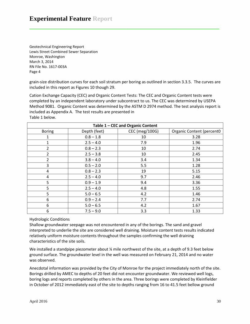
Cation Exchange Capacity (CEC) and Organic Content Tests: The CEC and Organic Content tests were completed by an independent laboratory under subcontract to us. The CEC was determined by USEPA Method 9081. Organic Content was determined by the ASTM D 2974 method. The test analysis report is included as Appendix A. The test results are presented in Table 1 below.
Table 1 – CEC and Organic Content Boring Depth (feet) CEC (meg/100G) Organic Content (percent0
1 0.8 – 1.8 10 3.28 1 2.5 – 4.0 7.9 1.96 2 0.8 – 2.3 10 2.74 2 2.5 – 3.8 10 2.45 2 3.8 – 4.0 3.4 1.34 3 0.5 – 2.0 5.5 1.28 4 0.8 – 2.3 19 5.15 4 2.5 – 4.0 9.7 2.46 5 0.9 – 1.9 9.4 3.36 5 2.5 – 4.0 4.8 1.55 5 5.0 – 6.5 4.2 1.46 6 0.9 – 2.4 7.7 2.74 6 5.0 – 6.5 4.2 1.67 6 7.5 – 9.0 3.3 1.33
Hydrologic Conditions Shallow groundwater seepage was not encountered in any of the borings. The sand and gravel interpreted to underlie the site are considered well draining. Moisture content tests results indicated relatively uniform moisture contents throughout the samples confirming the well draining characteristics of the site soils.
We installed a standpipe piezometer about ¼ mile northwest of the site, at a depth of 9.3 feet below ground surface. The groundwater level in the well was measured on February 21, 2014 and no water was observed.
Anecdotal information was provided by the City of Monroe for the project immediately north of the site. Borings drilled by AMEC to depths of 20 feet did not encounter groundwater. We reviewed well logs, boring logs and reports completed by others in the area. Three borings were completed by Kleinfielder in October of 2012 immediately east of the site to depths ranging from 16 to 41.5 feet bellow ground

Experimental Feature Report __________________________________________________________
April 2016 31
Geotechnical Engineering Report Lewis Street Combined Sewer Separation Monroe, Washington March 3, 2014 RN File No. 1617-003A Page 5 surface. Observations from the deepest boring indicated a groundwater level at approximately 28.5 feet below ground surface. The other borings were dry. A standpipe piezometer was installed by RH2 about ¼ mile southeast of the site, at a depth of approximately 19 feet below ground surface. The groundwater level in the well was measured on October 15, 2012 and no water was observed. Several wells were completed to depths of 30 feet by Farallon in November 2000 less than ¼ mile southeast of the site. These wells indicated groundwater levels ranging from 22 feet to greater than 30 feet below ground surface. Wells were completed by Zipper Zeman in March 2009 about ¼ mile northeast of the site. These well were installed to a depth of 20 feet below ground surface and indicated groundwater levels ranging from 14 feet to greater than 20 feet below ground surface.
CONCLUSIONS AND RECOMMENDATIONS General It is our opinion that the site is compatible with the planned development. The underlying medium dense to very dense sands and gravels are suitable for infiltration and pavement support. Groundwater levels were recorded at depths of 14 feet or greater below ground surface. Provided the infiltration gallery is placed within 9 feet of the ground surface, it will meet the DOE requirements of the minimum 5 feet of separation between the bottom of the infiltration gallery and the seasonal high groundwater mark. As noted above in the Hydrologic Conditions section of this report, the highest groundwater levels in the area were observed at 14 feet below ground surface.
Infiltration We understand stormwater along the North Lewis Street and East Main Street alignment is planned to be infiltrated through the use of pervious pavement in the parking lane. Based on our explorations, review of published geological maps and review of well logs within ¼ mile of the site, it is our opinion that these alignments are underlain by well-drained unsaturated soils to depths of at least 14 feet below ground surface. Section 3.3.7 of the DOE requires at least 5 feet of separation between the bottom of the infiltration gallery and the seasonal high water mark or other low permeability layer. This requirement will be met by placing the infiltration gallery within 9 feet of the existing ground surface.
Silty soils less suitable for infiltration were encountered at shallow depths. Coarse-grained soils more suitable for infiltration were encountered at depths ranging from 0.5 to 4.0 feet below ground surface. A storage gallery will be required to store and transport stormwater to the receptor soils below.
Infiltration rates at the site were determined using grain size distribution tests and procedures outlined in the 2005 DOE. Once a grain size distribution curve was created from the tests a D10 value was obtained. The D10 value is the particle diameter in millimeters at 10 percent of the sample passing the size listed. This D10 value is then used to determine a long term infiltration rated based on Table 3.8 of the DOE manual – Alternative Recommended Infiltration Rates based on ASTM Gradation Testing and on Figure 3.28 of the DOE manual – Infiltration Rate as a Function of the D10 Size of the Soil for Ponds in Western Washington. These rates represent average conditions regarding site variability, expected degree of maintenance and pre-treatment. We have concluded that the soils have little variability

Experimental Feature Report __________________________________________________________
April 2016 32
Geotechnical Engineering Report Lewis Street Combined Sewer Separation Monroe, Washington March 3, 2014 RN File No. 1617-003A Page 6 across the site based on the results of our laboratory tests and our observations from subsurface explorations.
The table below presents our recommended long-term infiltration rates that can be used to design the infiltration galleries. Cross-sections of the boring logs, soil types and long-term infiltration rates associated with those soils are presented in Figures 30 and 31.
Table 2 – Recommended Long-term Infiltration Rates
Boring Depth (feet) USGS Soil Classification D10 Infiltration Rate (in./hr)
1 1.8 – 2.3 SM 0.02 0.7 1 2.5 – 4.0 SW-SM 0.09 2.0 1 5.0 – 6.5 SP 0.18 2.0 1 7.5 – 9.0 GW-GM 0.11 2.0 2 2.5 – 3.8 GM 0.05* 0.7 2 3.8 – 4.0 GP 0.41 6.5 2 5.0 – 6.5 GP 0.26 6.5 2 7.5 – 9.0 GP 0.38 6.5 3 0.5 – 2.0 GW-GM 0.13 2.0 3 7.5 – 9.0 GW-GM 0.14 2.0 4 0.8 – 2.3 SM 0.02* 0.7 4 2.5 – 4.0 GP-GM 0.07* 0.7 4 5.0 – 6.5 SP-SM 0.14 2.0 4 7.5 – 9.0 GW-GM 0.15 2.0 5 0.9 – 1.9 SM 0.04 0.7 5 2.5 – 4.0 SP-SM 0.07* 0.7 5 5.0 – 6.5 GW-GM 0.20 2.0 6 0.9 – 2.4 GM 0.04 0.7 6 5.0 – 6.5 SP-SM 0.21 2.0 6 7.5 – 9.0 GP-GM 0.11 2.0
*Estimate by extrapolation
Cation Exchange Capacity (CEC) and Organic Content Cation exchange capacity (CEC) is the capacity of the soil for ion exchange of cations between the soil and the soil solution. CEC is used as a measure of fertility, nutrient retention capacity, and the capacity to protect the groundwater from cation contamination. Section 3.3.7 of the DOE discusses physical and chemical suitability criteria for treatment facilities. If the soil in the pavement area is planned to be used for treatment these test determine if the soil is adequate for removing target pollutants. The CEC of the treatment soil must be >/= 5 millequivallents CEC/100 grams (meg/100g) of dry soil as determined by

Experimental Feature Report __________________________________________________________
April 2016 33
Geotechnical Engineering Report Lewis Street Combined Sewer Separation Monroe, Washington March 3, 2014 RN File No. 1617-003A Page 7 USEPA Method 9081. Lower CEC content may be considered if it is based on a soils loading capacity determination for the target pollutants that is accepted by the City. Organic matter can increase the sorptive capacity of the soil for some pollutants. In other words, the greater the organic content of the soil, the greater the chance that certain pollutants will attach to the soil. Organic content was determined by the ASTM D 2974 method.
The CEC of the soils shallower than 1.9 feet across the site was >/= 5 millequivallents CEC/100 grams (meg/100g) of dry soil. These CEC values were also present to depths of 4.0 feet for Borings 1 and 4, 3.8 feet for Boring 2 and 2.4 feet for Boring 6. Table 1 in the Laboratory Testing section of this report presents the specific tested values.
We understand the bottom of the infiltration gallery could be as much as 2.5 feet below existing ground surface. The lowest CEC value at that depth was 4.8 in Boring 5. The organic content of that sample was 1.55 percent. In our opinion the slightly relatively higher organic content of the soil at that depth will increase the sorptive capacity of the soil sufficiently to compensate for the slightly lower CEC value.
Pervious Pavement Pervious pavement consists of specially formulated mixtures of Portland cement, uniform, open-graded coarse aggregate and water. This concrete has a low water-cement ratio and low slump and is primarily held together by cement paste as the contact points of the coarse aggregate. Pervious concrete has enough void space, typically 15 to 25%, to allow rapid percolation of liquids through the concrete.
We used the software program StreetPave 12 by the American Concrete Pavement Association to determine the appropriate pavement thickness for both alignments. Based on these results and our experience with pervious pavement design, we recommend the pavement consist of a minimum of 8.5-inch thickness of pervious Portland cement concrete for North Lewis Street and a minimum of 7.5-inch thickness of pervious Portland cement concrete for East Main Street for a 20-year design life.
Input values for StreetPave 12 include traffic data as well as soil and concrete properties. Traffic loading conditions for East Lewis Street were obtained from WSDOT’s 2012 Annual Traffic Report for SR 203 at mile post 24.16. Traffic loading conditions for West Main Street were provided for us by the City of Monroe from a traffic count performed in May and June of 2008 and modified per the City’s request to 100 trucks per day for East Main Street. We have assumed a 2% growth rate. Soil properties were correlated from the SPT blow counts and the laboratory tests. Concrete properties were assumed based on compression strength break data for pervious concrete of approximately 2,000 psi. The input values for flexural strength were correlated from the compressive strength values. The input values and design thickness results are provided in Appendix B.
The computed Equivalent Single Axle Load (ESAL) from the StreetPave 12 program were 15,850,116 for North Lewis Street and 604,225 for East Main Street. We also evaluated the ESALs for East Main Street using the methods presented in the 1993 AASHTO Design of Pavement Structures manual. The results of this method are included in Appendix B. The methods used in StreetPave 12 are significantly more conservative than the AASHTO method.

Experimental Feature Report __________________________________________________________
April 2016 34
Geotechnical Engineering Report Lewis Street Combined Sewer Separation Monroe, Washington March 3, 2014 RN File No. 1617-003A Page 8 Failure of the new pavement will likely occur through cracking. In order to limit post-construction cracking, we recommend that expansion joints be saw cut a maximum of 13 feet on center. The program suggests that dowels are not needed unless the cause of failure is fatigue and the pavement thickness is greater than or equal to 8 inches.
We understand that the pervious pavement will be constructed adjacent to the existing asphalt and concrete pavement on the travel lane side and adjacent to the curb on the pedestrian sidewalk side. The potential for softening of the existing pavement subgrade over time could occur with an adjacent pervious pavement infiltration gallery. We therefore recommend using a concrete curb or geomembrane between the existing pavement and the planned pervious pavement and infiltration gallery as shown in Figure 32.
A pervious pavement section typically consists of the pervious cement concrete section underlain by an open-graded subbase that also serves as a storage bed. A pervious pavement cross-section is shown in Figure 32. We recommend a minimum 8-inch thickness for the reservoir course. The reservoir course should be designed to hold water for the design storm event while making sure the water will drain within a 24 to 72-hour period for proper water treatment. Other options, such as subdrains may also be considered for overflow.
Protecting the pervious pavement from high sediment loads is critical during construction. Runoff from disturbed areas must be diverted away from the pervious pavement. Appropriate Best Management Practices (BMPs) should be used to prevent run-on to the pervious pavement.
After construction, surface inspections should be conducted on a regular basis, particularly after storm events to check for surface ponding that might indicate possible clogging. We recommend vacuum sweeping or high pressure hosing 2 to 4 times per year. Sand should not be used for winter maintenance as the sand will clog the pores.
Site Preparation and Grading The first step of site preparation should be to remove the existing pavement to expose medium dense to firmer native soils in planned pavement areas. The excavated material should be removed from the site, or stockpiled for later use as landscaping fill. Areas observed to pump or yield should be repaired prior to placing hard surfaces.
The on-site silty sand and silty gravel likely to be exposed during construction is considered highly moisture sensitive, and the surface will disturb easily when wet. We expect these soils would be difficult, if not impossible, to compact to structural fill specifications in wet weather. We recommend that earthwork be conducted during the drier months. Additional expenses of wet weather or winter construction could include extra excavation and use of imported fill or rock spalls. During wet weather, alternative site preparation methods may be necessary. These methods may include utilizing a smooth-bucket trackhoe to complete site stripping and diverting construction traffic around prepared subgrades. Disturbance to the prepared subgrade may be minimized by placing a blanket of rock spalls or imported sand and gravel in traffic and roadway areas.

Experimental Feature Report __________________________________________________________
April 2016 35
Geotechnical Engineering Report Lewis Street Combined Sewer Separation Monroe, Washington March 3, 2014 RN File No. 1617-003A Page 9 Structural Fill General: All fill placed beneath pavements or other settlement sensitive features should be placed as structural fill. Structural fill, by definition, is placed in accordance with prescribed methods and standards, and is observed by an experienced geotechnical professional or soils technician. Field observation procedures would include the performance of a representative number of in-place density tests to document the attainment of the desired degree of relative compaction. Materials: Imported structural fill should consist of a good quality, free-draining granular soil, free of organics and other deleterious material, and be well graded to a maximum size of about 3 inches. Imported, all-weather structural fill should contain no more than 5 percent fines (soil finer than a Standard U.S. No. 200 sieve), based on that fraction passing the U.S. 3/4-inch sieve. The use of on-site soil as structural fill will be dependent on moisture content control. Some drying of the native soils may be necessary in order to achieve compaction. During warm, sunny days this could be accomplished by spreading the material in thin lifts and compacting. Some aeration and/or addition of moisture may also be necessary. We expect that compaction of the native soils to structural fill specifications would be difficult, if not impossible, during wet weather. Fill Placement: Following subgrade preparation, placement of the structural fill may proceed. Fill should be placed in 6- to 10-inch-thick uniform lifts, depending on the equipment used, and each lift should be spread evenly and be thoroughly compacted prior to placement of subsequent lifts. All structural fill within a depth of 2 feet below pavement subgrade, should be compacted to at least 95 percent of its maximum dry density. Maximum dry density, in this report, refers to that density as determined by the ASTM D1557 compaction test procedure. Fill more than 2 feet beneath pavement subgrades should be compacted to at least 90 percent of the maximum dry density. The moisture content of the soil to be compacted should be within about 2 percent of optimum so that a readily compactable condition exists. It may be necessary to overexcavate and remove wet surficial soils in cases where drying to a compactible condition is not feasible. All compaction should be accomplished by equipment of a type and size sufficient to attain the desired degree of compaction. Density and moisture testing is typically performed with a nuclear moisture-density gage. It has been our experience that nuclear density testing of clean crushed rock can be difficult if not impossible due to the action of driving the pilot pin into the rock, the void spaces between the rock and the caving of rock into the pilot hole. In addition, the laboratory Proctor tests on this type of material can break the rock structure, which does not typically occur in the field and which will give a higher density result that is actually attained in the field. We have also observed that even a small change in the fraction of material passing the #40 sieve can cause the density result to appear higher than is obtained in the field. We therefore recommend that when clean crushed rock is used, the rock be compacted to a firm and unyielding condition as determined through observation and probing.

Experimental Feature Report __________________________________________________________
April 2016 36
Geotechnical Engineering Report Lewis Street Combined Sewer Separation Monroe, Washington March 3, 2014 RN File No. 1617-003A Page 10 Temporary Slopes Temporary cut slope stability is a function of many factors, such as the type and consistency of soils, depth of the cut, surcharge loads adjacent to the excavation, length of time a cut remains open, and the presence of surface or groundwater. It is exceedingly difficult under these variable conditions to estimate a stable temporary cut slope geometry. Therefore, it should be the responsibility of the contractor to maintain safe slope configurations, since the contractor is continuously at the job site, able to observe the nature and condition of the cut slopes, and able to monitor the subsurface materials and groundwater conditions encountered. For planning purposes, we recommend that temporary cuts in the near-surface weathered soils and the sand and gravel be no steeper than 1.5 Horizontal to 1 Vertical (1.5H:1V). If groundwater seepage is encountered, we would expect that flatter inclinations would be necessary. We recommend that cut slopes be protected from erosion. Measures taken may include covering cut slopes with plastic sheeting and diverting surface runoff away from the top of cut slopes. We do not recommend vertical slopes for cuts deeper than 4 feet, if worker access is necessary. We recommend that cut slope heights and inclinations conform to local and WISHA/OSHA standards. Pavement Subgrade The performance of roadway pavement is critical to the conditions of the underlying subgrade. We recommend that the subgrade soils within the roadways be prepared as described in the Site Preparation and Grading subsection of this report. Prior to placing base material, the subgrade soils should be lightly compacted to a non-yielding state. Overcompaction should be avoided to allow for infiltration. Any areas with excessive weaving or flexing should be overexcavated and recompacted or replaced with a structural fill or crushed rock placed and compacted in accordance with recommendations provided in the Structural Fill subsection of this report. CONSTRUCTION OBSERVATION We should be retained to provide observation and consultation services during construction to confirm that the conditions encountered are consistent with those indicated by the explorations, and to provide recommendations for design changes, should the conditions revealed during the work differ from those anticipated. As part of our services, we would also evaluate whether or not earthwork and foundation installation activities comply with contract plans and specifications. USE OF THIS REPORT We have prepared this report for the City of Monroe and its agents, for use in planning and design of this project. The data and report should be provided to prospective contractors for their bidding and estimating purposes, but our report, conclusions and interpretations should not be construed as a warranty of subsurface conditions.

Experimental Feature Report __________________________________________________________
April 2016 37
Geotechnical Engineering Report Lewis Street Combined Sewer Separation Monroe, Washington March 3, 2014 RN File No. 1617-003A Page 11 The scope of our services does not include services related to construction safety precaution, and our recommendations are not intended to direct the contractor’s methods, techniques, sequences or procedures, except as specifically described in our report, for consideration in design. There are possible variations in subsurface conditions. We recommend that project planning include contingencies in budget and schedule, should areas be found with conditions that vary from those described in this report. Within the limitation of scope, schedule and budget for our services, we have strived to take care that our services have been completed in accordance with generally accepted practices followed in this area at the time this report was prepared. No other conditions, expressed or implied, should be understood. We appreciate the opportunity to be of service to you. If there are any questions concerning this report or if we can provide additional services, please call. Sincerely, Robinson Noble, Inc. Rick B. Powell, PE Principal Engineer Barbara A. Gallagher, PE Senior Project Engineer BAG:RBP:am Five Copies Submitted Thirty-two Figures Appendix A and B

Experimental Feature Report __________________________________________________________
April 2016 38
Appendix C Contract Special Provisions

Experimental Feature Report __________________________________________________________
April 2016 39
Division 5 Surface Treatments and Pavements 5-03 PERMEABLE ARTICULATING CONCRETE BLOCK/MAT (NEW SECTION) (*****) Specification for permeable articulating block/mat shall be by the document “Permeable Articulating Concrete Block/Mat” attached to this contract as an appendix. 5-03(4) Measurement (new section) The unit measurement for Permeable Articulating Concrete Block/Mat is per square foot, as shown in the Bid Schedule. 5-03(5) Payment (new section) Payment for Permeable Articulating Concrete Block/Mat shall include all equipment, material and labor necessary to fine grade, assemble, transport, place, install end caps, and other work necessary to install the product in accordance with the plans. 5-05.3(18) Pervious Concrete (new section) (*****) Specification for pervious concrete shall be by document ACI 522.1-08, Specification for Pervious Concrete Pavement, An ACI Standard as published by the American Concrete Institute. The document is attached to this contract as an appendix. Replace ACI Standard section 2.2.1 “Aggregate” with the following: Pervious concrete shall use uniformly graded crushed coarse aggregate meeting AASHTO grading No.8 with no fine aggregate and a water to cement ratio ranging from 0.27 to 0.35. The unit weight of the mix is between 100 and 125 pcf with a porosity of 15% to 25%. The permeability of the hardened product is between 300 and 800 in/hr. Test panels shall be cast on site and per standard installation procedures as outlined in ACI 522.1-08. The Contractor may construct test panels at the location and final grade of the permanent Work. At the discretion of the Engineer, the test panels may be incorporated into the site improvements if the test panels are deemed acceptable as determined by the Engineer. 5-05.3(18) Porous Concrete (new section) (*****) Specification for porous concrete shall be by document ACI 522.1-08, Specification for Pervious Concrete Pavement, An ACI Standard as published by the American Concrete Institute. The document is attached to this contract as an appendix. Replace ACI Standard section 2.2.1 “Aggregate” with the following: Porous concrete shall use uniformly graded crushed coarse aggregate meeting AASHTO grading No.8 with no fine aggregate and a water to cement ratio ranging from 0.27 to 0.35. The unit weight of the mix is between 100 and 125 pcf with a porosity of 15% to 25%.

Experimental Feature Report __________________________________________________________
April 2016 40
The permeability of the hardened product is between 300 and 800 in/hr. Test panels shall be cast on site and per standard installation procedures as outlined in ACI 522.1-08. The Contractor may construct test panels at the location and final grade of the permanent Work. At the discretion of the Engineer, the test panels may be incorporated into the site improvements if the test panels are deemed acceptable as determined by the Engineer.

Experimental Feature Report __________________________________________________________
April 2016 41
Appendix D
Work Plan

Experimental Feature Report __________________________________________________________
April 2016 42
Washington State Department of Transportation
WORK PLAN
Pervious Concrete Parking Strips
City of Monroe Lewis and Main Street
SR-203
Keith W. Anderson Experimental Features Engineer
Washington State Department of Transportation
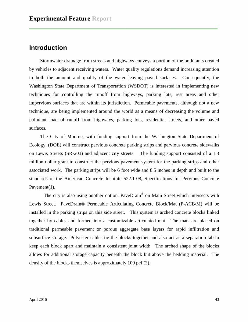
Experimental Feature Report __________________________________________________________
April 2016 43
Introduction
Stormwater drainage from streets and highways conveys a portion of the pollutants created
by vehicles to adjacent receiving waters. Water quality regulations demand increasing attention
to both the amount and quality of the water leaving paved surfaces. Consequently, the
Washington State Department of Transportation (WSDOT) is interested in implementing new
techniques for controlling the runoff from highways, parking lots, rest areas and other
impervious surfaces that are within its jurisdiction. Permeable pavements, although not a new
technique, are being implemented around the world as a means of decreasing the volume and
pollutant load of runoff from highways, parking lots, residential streets, and other paved
surfaces.
The City of Monroe, with funding support from the Washington State Department of
Ecology, (DOE) will construct pervious concrete parking strips and pervious concrete sidewalks
on Lewis Streets (SR-203) and adjacent city streets. The funding support consisted of a 1.3
million dollar grant to construct the pervious pavement system for the parking strips and other
associated work. The parking strips will be 6 foot wide and 8.5 inches in depth and built to the
standards of the American Concrete Institute 522.1-08, Specifications for Pervious Concrete
Pavement(1).
The city is also using another option, PaveDrain® on Main Street which intersects with
Lewis Street. PaveDrain® Permeable Articulating Concrete Block/Mat (P-ACB/M) will be
installed in the parking strips on this side street. This system is arched concrete blocks linked
together by cables and formed into a customizable articulated mat. The mats are placed on
traditional permeable pavement or porous aggregate base layers for rapid infiltration and
subsurface storage. Polyester cables tie the blocks together and also act as a separation tab to
keep each block apart and maintain a consistent joint width. The arched shape of the blocks
allows for additional storage capacity beneath the block but above the bedding material. The
density of the blocks themselves is approximately 100 pcf (2).

Experimental Feature Report __________________________________________________________
April 2016 44
Plan of Study
The objective of this experimental feature is to evaluate the short term performance of the
pervious concrete. Visual inspections will be conducted on an annual basis to determine the
physical condition of the concrete with respect to cracking or other distress. Additional, the
impacts of using shoulder infiltration as contrasted with traditional shoulder drains will be
accessed during storm events. Impact may include minor accumulation of water on the pervious
strips to flooding of the driving lanes and performance of adjacent impermeable pavement due to
the effects of infiltrating and storing storm water. WSDOT maintenance personnel will be
interviewed to determine their assessments of the performance of the parking strips and any
additional problems generated by their use.
The performance of the PaveDrain® parking strips and the pervious concrete sidewalks
will be noted as a secondary issue of interest (2). WSDOT has an interest in all types of pervious
pavement as possible infiltration solutions for stormwater generated from transportation
facilities.
Scope
A sample roadway section for Lewis Street is shown in Figure 1. The total centerline
length of the parking strips on Lewis Street is 620 feet. The amount of pervious concrete listed
in the bid sheets was 1,791 square yards.
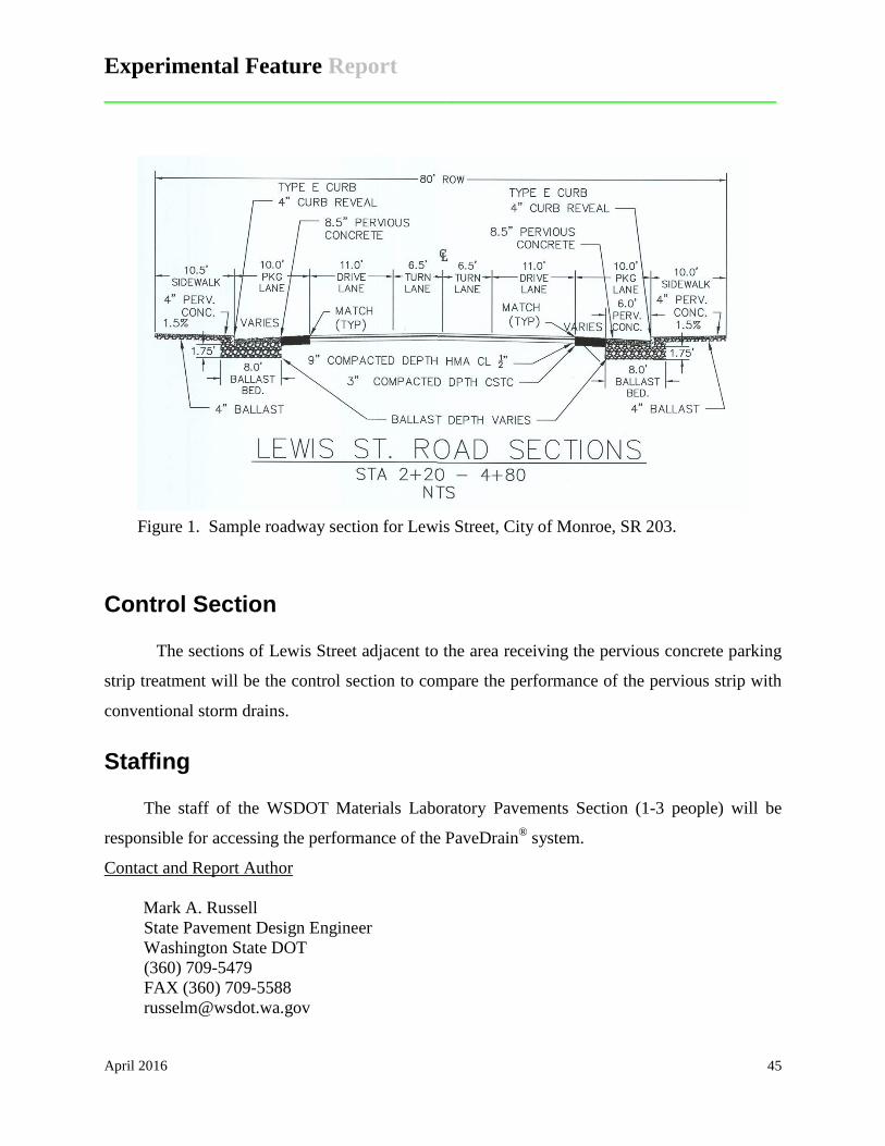
Experimental Feature Report __________________________________________________________
April 2016 45
Figure 1. Sample roadway section for Lewis Street, City of Monroe, SR 203.
Control Section
The sections of Lewis Street adjacent to the area receiving the pervious concrete parking
strip treatment will be the control section to compare the performance of the pervious strip with
conventional storm drains.
Staffing
The staff of the WSDOT Materials Laboratory Pavements Section (1-3 people) will be
responsible for accessing the performance of the PaveDrain® system.
Contact and Report Author
Mark A. Russell State Pavement Design Engineer Washington State DOT (360) 709-5479 FAX (360) 709-5588 [email protected]

Experimental Feature Report __________________________________________________________
April 2016 46
Reporting
An “End of Construction” report will be written following completion of the project. This
report will include construction details and other details concerning the overall process. Annual
inspections will be conducted over the next five years. At the end of the five-year period, a final
report will be written which summarizes performance characteristics and future
recommendations for use of this system.
Evaluation Cost Estimate Testing
Condition assessments: One full day at $132/hr., six times over the 5 year evaluation period, ($132 x 8 x 6 = $6,336).
Reporting
Initial Report – 60 hours = $7,920 Annual Report – 20 hours (4 hours each) = $2,640 Final Report – 100 hours = $13,200
Reporting Cost: $23,760 Total Evaluation Cost: $30,096
Schedule
Construction – May 2015
Date Condition
Survey (Annual)
End of Construction
Report Final
Report
Fall 2015 X X Fall 2016 X Fall 2017 X Fall 2018 X Fall 2019 X
Spring 2020 X

Experimental Feature Report __________________________________________________________
April 2016 47
References
(1) American Concrete Institute, “Specifications for Pervious Concrete Pavement”, ACI 522.1-08, March 2008.
(2) PaveDrain® Web Site, http://pavedrain.com/